EP1816453A2 - Systems and methods for remote monitoring of vibrations in machines - Google Patents
Systems and methods for remote monitoring of vibrations in machines Download PDFInfo
- Publication number
- EP1816453A2 EP1816453A2 EP07101565A EP07101565A EP1816453A2 EP 1816453 A2 EP1816453 A2 EP 1816453A2 EP 07101565 A EP07101565 A EP 07101565A EP 07101565 A EP07101565 A EP 07101565A EP 1816453 A2 EP1816453 A2 EP 1816453A2
- Authority
- EP
- European Patent Office
- Prior art keywords
- machine
- vibration
- optics module
- interrogator
- reflective patch
- Prior art date
- Legal status (The legal status is an assumption and is not a legal conclusion. Google has not performed a legal analysis and makes no representation as to the accuracy of the status listed.)
- Granted
Links
- 238000012544 monitoring process Methods 0.000 title claims abstract description 19
- 238000000034 method Methods 0.000 title abstract description 10
- 238000001514 detection method Methods 0.000 claims abstract description 23
- 238000004458 analytical method Methods 0.000 description 9
- 230000036541 health Effects 0.000 description 7
- 238000002955 isolation Methods 0.000 description 4
- 238000004891 communication Methods 0.000 description 3
- 238000007619 statistical method Methods 0.000 description 3
- 238000012986 modification Methods 0.000 description 2
- 230000004048 modification Effects 0.000 description 2
- 238000012545 processing Methods 0.000 description 2
- 230000008439 repair process Effects 0.000 description 2
- 210000004712 air sac Anatomy 0.000 description 1
- 230000008901 benefit Effects 0.000 description 1
- 230000005540 biological transmission Effects 0.000 description 1
- 230000008859 change Effects 0.000 description 1
- 238000013016 damping Methods 0.000 description 1
- 238000007405 data analysis Methods 0.000 description 1
- 238000005516 engineering process Methods 0.000 description 1
- 230000006870 function Effects 0.000 description 1
- 230000036449 good health Effects 0.000 description 1
- 238000009434 installation Methods 0.000 description 1
- 230000002452 interceptive effect Effects 0.000 description 1
- 238000012423 maintenance Methods 0.000 description 1
- 238000004519 manufacturing process Methods 0.000 description 1
- 230000003287 optical effect Effects 0.000 description 1
- 230000005855 radiation Effects 0.000 description 1
- 230000003595 spectral effect Effects 0.000 description 1
Images


Classifications
-
- G—PHYSICS
- G01—MEASURING; TESTING
- G01H—MEASUREMENT OF MECHANICAL VIBRATIONS OR ULTRASONIC, SONIC OR INFRASONIC WAVES
- G01H9/00—Measuring mechanical vibrations or ultrasonic, sonic or infrasonic waves by using radiation-sensitive means, e.g. optical means
Definitions
- This invention relates to systems and methods for monitoring vibrations in machines and more particularly relates to the remote monitoring of vibrational information using electromagnetic interrogator beams.
- transducers may be attached to, or placed in contact with, the machine housing so as to monitor the vibration. Subsequent analysis of the vibrational information determined by the transducers may provide valuable diagnostic data relating to the health of the monitored machinery.
- a transducer must be attached at every location in which monitoring of the vibration is desired. The health of the individual transducer also must be further monitored to ensure that the transducer is properly operating. In a facility employing thousands of machines, the purchase, installation, maintenance, and repair of thousands of transducers can become excessively expensive.
- portable data collectors may be used to monitor the health of the monitored machinery.
- the PDC's are mobile devices that include a transducer and recording means to monitor the health of the machines.
- the PDC is transported to a machine and the transducer is placed in contact with the housing of the machine.
- the PDC can then record the vibrations of the housing. These recordings are subsequently analyzed in an attempt to assess the health of the machine. Operators must personally visit each machine and operate the PDC to record the vibrational information. The PDC operator may, therefore, spend an exorbitant amount of time monitoring the machines.
- a system for monitoring the vibration of a machine may include a reflective patch affixed to the machine and a vibration detection unit.
- the vibration detection unit includes an optics module, wherein the optics module transmits an interrogator beam to a reflective patch and the reflective patch reflects a vibration modulated beam to the vibration detection unit.
- the optics module of the vibration detection unit may then demodulate the interrogator beam to determine the vibration of the machine.
- the interrogator beam is a laser beam.
- the reflective patch is retro reflective tape.
- Another aspect of the invention includes a beam reflector operable for receiving the interrogator beam from the optics module and reflecting the interrogator beam to the reflective patch and operable for receiving the vibration modulated beam reflected from the reflective patch and reflecting the vibration modulated beam to the vibration detection unit.
- the optics module also may be oriented by a control module so that the interrogator beam can be directed at the reflective patch affixed to the machine or to a plurality of machines.
- the optics module also may be oriented to transmit the interrogator beam to at least one of the plurality of machines remotely.
- the optics module may further be rotatable in at least one angle.
- the optics module may include a processor for demodulating the vibration modulated beam.
- a method for monitoring the vibration of at least one machine may include affixing at least one reflective patch to at least one machine, positioning a vibration detection unit, comprising an optics module, remotely from the at least one machine, transmitting an interrogator beam from the optics module to the at least one reflective patch affixed to the at least one machine, reflecting a vibration modulated beam from the at least one reflective patch to the optics module, and demodulating the vibration modulated beam to determine the vibration of the at least one machine.
- the method may include providing a beam reflector operable for receiving the interrogator beam from the optics module, reflecting the interrogator beam from the beam reflector to the reflective patch, receiving the interrogator beam reflected from the reflective patch, and reflecting the vibration modulated beam to the optics module.
- a method for analyzing a plurality of machines from at least one facility includes affixing at least one reflective patch to the plurality of machines in the at least one facility, positioning a vibration detection unit comprising an optics module remotely from the plurality of machines in the at least one facility, transmitting an interrogator beam from the optics module to the at least one reflective patch affixed to the plurality of machines in the at least one facility, reflecting a vibration modulated beam from the at least one reflective patch to the optics module in the at least one facility, demodulating the vibration modulated beam to determine the vibrational data of the at least one machine, transmitting the vibrational data of the at least one machine to a remote analysis facility, and determining statistical information from the vibrational data of the at least one machine from the plurality of facilities.
- the statistical information is determined for a particular model of machine.
- the statistical information is determined for a particular manufacturer of machine.
- the statistical information is determined for a particular manufacturer of machine.
- FIG. 1a illustrates a remote monitoring system 100 for the remote monitoring of the vibrations of a machine 110.
- the embodiment of FIG. 1a may be included in a factory, warehouse, or any other facility that requires the use of machinery.
- the remote monitoring system 100 may include a vibration detection unit 120 and a reflective patch 130.
- the vibration detection unit 120 may include a control module 150 and an optics module 160 that emits an interrogator beam 145.
- the control module may include a general purpose computer, special purpose computer, microprocessor, other programmable data processing apparatus, or a computer-readable memory that can direct a computer or other programmable data processing apparatus to function in accordance with this invention.
- the interrogator beam 145 may be an electromagnetic beam.
- the electromagnetic beam may be a laser beam or any other suitable energy beam that can be used to detect vibrations of a machine.
- the optics module 160 is a vibrometer manufactured by Polytec, Inc. of Tustin, California.
- the optics module 160 may be any device or system of devices operable for the transmission and reception of an interrogator beam.
- the vibration detection unit 120 may be located in any location in which it is operable to monitor the vibration of a machine.
- the vibration detection unit 120 is attached to a structural frame of a facility ceiling.
- the vibration detection unit 120 may be mounted on a movable system positioned to allow the optics module 160 to emit the electromagnetic beam to a desired location.
- FIGS. 1b and 1c illustrate exemplary embodiments of the optics module 160 affixed to a movable system to allow the optics module 160 to interrogate machines positioned at various locations in a facility. As shown in FIG. 1b, the optics module 160 may be affixed to a train 162 located about the ceiling of the facility.
- the train 162 may interface a track 164 at or near the ceiling of the facility.
- the train 162 may move in relation to the track 164 so that the train may be positioned with respect to any desired machine or sets of machines.
- the train 162 may be moved about the track either manually or electronically guided.
- the optics module 160 may be affixed to a mobile cart 166 that may move about the floor of the facility.
- the mobile cart 166 may interface the floor directly or may interface a track (not shown).
- the mobile cart 166 includes casters 168 to allow the mobile cart 166 to roll about the floor.
- the mobile cart 166 may be moved either manually or electronically guided.
- the optics module 160 may be oriented about one or more rotational and/or translational degrees of freedom. One of ordinary skill in the art will appreciate that any number of angular degrees of freedom are contemplated herein.
- the optics module 160 may be adjustable to control characteristics of the emitted interrogator beam 145, including but not limited to adjustment of the focal length, power, and multiplicity of beams. The adjustments may be performed electromechanically under the control of a software program or manually by an operator.
- the control module 150 controls the beam pointing direction of the optics module 160 and other adjustments to the optics module 160 such as the focal length of the emitted interrogator beam 145.
- the control module 150 may also receive external commands respecting the operation of the optics module 160 and the control module 150 may also report out the demodulated vibration data to an external or remote analysis facility.
- the optics module may be rotated to direct the interrogator beam at a reflective target on a substantially stationary surface to perform a diagnostic check for vibration of the optics module.
- the reflective patch 130 of the remote monitoring system 100 may be affixed to the machine 110.
- the reflective patch 130 may be affixed at any location on the machine 110.
- a plurality of reflective patches also may be affixed to the machine in a number of locations on the machine for use in monitoring vibrations of different components or locations of the machine.
- the reflective patch 130 may be a retro reflective patch that receives the interrogator beam at a normal or non-normal angle of incidence and reflects the interrogator beam 145 along the same or similar angle of incidence.
- the reflective patch 130 is operable to reflect an interrogator beam 145 that is tens of degrees off-axis to a vector normal to the reflective patch 130 surface.
- the reflective patch 130 is a retro reflective tape. The retro reflective tape may be easily affixed to a machine and allows a beam to be reflected at the same or similar angle of incidence as the incoming beam.
- the retro reflective tape of the exemplary embodiment may be commercially available tape, including but not limited to reflective tape sold by Reflexite Americas of New Britian, Connecticut, or tape designed and manufactured specifically for use in this invention.
- the reflective patch 130 includes at least one corner cube reflector.
- any reflective patch may be employed to reflect a beam along the same or similar angle of incidence of the transmitted beam, including but not limited to a mirror or other types of retro reflective tape.
- the optics module 160 may transmit the interrogator beam 145 towards the reflective patch 130 affixed to the machine 110.
- the interrogator beam 145 travels to the reflective patch 130 affixed to the housing of the monitored machine 110.
- the reflective patch 130 receives the interrogator beam 145 and reflects the interrogator beam as a vibration modulated beam 170.
- the vibration modulated beam 170 returns to the optics module 160 along the same or similar path as the interrogator beam 145. Due to the vibration of the machine and in turn the vibration of the reflective patch affixed thereto, the vibration modulated beam 170 will carry the vibration information of the machine 110.
- the vibration modulated beam 170 is demodulated in the optics module 160 and the machine vibrational data is recovered.
- the optics module 160 may also include an optical filter to filter out ambient radiation that is outside of the very narrowband spectral range of the vibration modulated beam 170. Demodulation of the vibration modulated beam is well-understood by persons skilled in the art and a person of ordinary skill in the art will appreciate that any appropriate method or system may be employed to demodulate the vibration modulated beam to determine the vibrational information contained therein, including Doppler shift demodulation.
- the vibration detection unit 120 may further include a vibration isolation unit 180 that mitigates structural borne vibrations from interfering with the vibrational data embedded in the vibration modulated beam 170.
- the vibration isolation unit 180 may be installed between the vibration detection unit 120 and its host structure. Vibration isolation units are well known in the art and are commercially available. They are based on one or a combination of multiple technologies including, but not limited to, spring and beam column isolators, air bladders, and viscoelastic damping materials.
- the components of the vibration detection unit may be integrated into one system or may include separate components.
- the optics module 160 and the control module 150 are separate components that are mounted together in a facility.
- the optics module 160 and the control module 150 are an integrated system.
- the components of the vibration detection unit reside in different locations.
- the optics module 160 may be located in a room containing the machine to be monitored and the control module 150 may be located in a separate room or completely separate location than the facility.
- the vibration detection unit 120 may be used to monitor the vibration of each of a plurality of machines 110.
- a reflective patch 130 may be affixed to the number of machines to be monitored.
- the angular and/or translational pointing position of the optics module 160 may be controlled through a software control system resident in the control module 150 or manually controlled through electro-mechanical controls.
- the optics module 160 may be rotated about a number of angles to align the interrogator beam with the reflective patch of a monitored machine.
- the optics module 160 may further be mounted on at least one track (not shown) to allow the optics module 160 to translate linearly with respect to the number of machines to optimize the incidence angle of the interrogator beam 145 onto the reflective patch 130 of the monitored machine.
- any means for positioning the optics module 160 such that it can transmit an interrogator beam 145 to the reflective patch 130 is contemplated herein.
- FIG. 2 illustrates a situation in which an obstruction 210 blocks the interrogator beam 145 from being transmitted in a straight line from the optics module 160 to the reflective patch 130.
- a beam reflector 220 may be used to reflect the interrogator beam around the obstruction.
- the beam reflector 220 may be aligned so that the interrogator beam 145 is redirected from the optics module 160 to the reflective patch 130.
- the beam reflector 220 may be affixed in any location proximate to the reflective patch 130 and the optics module 160.
- the beam reflector 220 is attached to a structural frame such as a factory ceiling using an attachment unit 225.
- the attachment unit 225 may include a beam reflector vibration isolation unit 230.
- the beam reflector 220 also may include a remotely controlled rotator unit to change the angles of incidence and reflection of the interrogator beam 145 in order to monitor a number of machines.
- a remotely controlled rotator unit to change the angles of incidence and reflection of the interrogator beam 145 in order to monitor a number of machines.
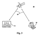
- FIG. 3 illustrates a two-way communications link 330 between a facility 310 housing the plurality of monitored machines and a remote analysis facility 320.
- the remote analysis facility 320 may be used to analyze the vibration data to determine strategies for resolving the vibrational concerns related to the machines.
- the communications link 330 may be satellite-based, fiber-optic, land-based, radio, wire-line, the Internet, or any other data transport facility.
- the remote analysis facility 320 may include any processor-driven device, such as a personal computer, laptop computer, handheld computer and the like which may further include a memory, input/output ("I/O") interface(s) and a network interface.
- the memory may store data files and various computer executable programs, such as an operating system ("OS”) and a data analysis program.
- OS operating system
- the remote analysis facility 320 may analyze the vibrational data from one or a number of machines from at least one facility using the data analysis program.
- the data analysis program may include a statistical analysis of the vibrational data.
- the remote analysis facility may determine statistical information relating to a particular model or manufacturer of machines in a number of facilities. In another embodiment, the remote analysis facility may determine statistical information on all machines in one particular facility.
- this invention is not limited to the aforementioned statistical analyses but may be any statistical analysis relating to the plurality of machines.
Landscapes
- Physics & Mathematics (AREA)
- General Physics & Mathematics (AREA)
- Measurement Of Mechanical Vibrations Or Ultrasonic Waves (AREA)
Abstract
Description
- This invention relates to systems and methods for monitoring vibrations in machines and more particularly relates to the remote monitoring of vibrational information using electromagnetic interrogator beams.
- Factories, warehouses, and other facilities typically employ various types of machines for the manufacture or distribution of products. Because such machinery generally includes parts in motion, vibrations are generated from an individual machine and transmitted to the machine housing. Excessive vibration or vibrational modes of a particular character may indicate an unhealthy machine that may be in need of repair. Thus, it is common to monitor the vibration of a machine to prevent possible damage.
- In order to determine the magnitude and nature of the vibration, transducers may be attached to, or placed in contact with, the machine housing so as to monitor the vibration. Subsequent analysis of the vibrational information determined by the transducers may provide valuable diagnostic data relating to the health of the monitored machinery. However, to monitor all machines, a transducer must be attached at every location in which monitoring of the vibration is desired. The health of the individual transducer also must be further monitored to ensure that the transducer is properly operating. In a facility employing thousands of machines, the purchase, installation, maintenance, and repair of thousands of transducers can become excessively expensive.
- Alternatively, portable data collectors (PDC's) may be used to monitor the health of the monitored machinery. The PDC's are mobile devices that include a transducer and recording means to monitor the health of the machines. The PDC is transported to a machine and the transducer is placed in contact with the housing of the machine. The PDC can then record the vibrations of the housing. These recordings are subsequently analyzed in an attempt to assess the health of the machine. Operators must personally visit each machine and operate the PDC to record the vibrational information. The PDC operator may, therefore, spend an exorbitant amount of time monitoring the machines.
- These current methods of monitoring the health of machines generally are expensive and time consuming. Often, a machine is in good health and does not require an extensive diagnostic check up. On the contrary, a failing machine may require more frequent data analyses. Thus, significant resources may be wasted. Therefore, there is a need in the art for a system and method for efficient remote monitoring of the vibrational health of a machine.
- According to one embodiment of the invention, a system for monitoring the vibration of a machine may include a reflective patch affixed to the machine and a vibration detection unit. The vibration detection unit includes an optics module, wherein the optics module transmits an interrogator beam to a reflective patch and the reflective patch reflects a vibration modulated beam to the vibration detection unit. The optics module of the vibration detection unit may then demodulate the interrogator beam to determine the vibration of the machine. In one embodiment of the invention, the interrogator beam is a laser beam. In another aspect of the invention the reflective patch is retro reflective tape.
- Another aspect of the invention includes a beam reflector operable for receiving the interrogator beam from the optics module and reflecting the interrogator beam to the reflective patch and operable for receiving the vibration modulated beam reflected from the reflective patch and reflecting the vibration modulated beam to the vibration detection unit. The optics module also may be oriented by a control module so that the interrogator beam can be directed at the reflective patch affixed to the machine or to a plurality of machines. The optics module also may be oriented to transmit the interrogator beam to at least one of the plurality of machines remotely. The optics module may further be rotatable in at least one angle. According to yet another aspect of the invention, the optics module may include a processor for demodulating the vibration modulated beam.
- According to another embodiment of the invention, a method for monitoring the vibration of at least one machine may include affixing at least one reflective patch to at least one machine, positioning a vibration detection unit, comprising an optics module, remotely from the at least one machine, transmitting an interrogator beam from the optics module to the at least one reflective patch affixed to the at least one machine, reflecting a vibration modulated beam from the at least one reflective patch to the optics module, and demodulating the vibration modulated beam to determine the vibration of the at least one machine. In another aspect of the invention, the method may include providing a beam reflector operable for receiving the interrogator beam from the optics module, reflecting the interrogator beam from the beam reflector to the reflective patch, receiving the interrogator beam reflected from the reflective patch, and reflecting the vibration modulated beam to the optics module.
- According to another embodiment of the invention, a method for analyzing a plurality of machines from at least one facility. In this embodiment, the method includes affixing at least one reflective patch to the plurality of machines in the at least one facility, positioning a vibration detection unit comprising an optics module remotely from the plurality of machines in the at least one facility, transmitting an interrogator beam from the optics module to the at least one reflective patch affixed to the plurality of machines in the at least one facility, reflecting a vibration modulated beam from the at least one reflective patch to the optics module in the at least one facility, demodulating the vibration modulated beam to determine the vibrational data of the at least one machine, transmitting the vibrational data of the at least one machine to a remote analysis facility, and determining statistical information from the vibrational data of the at least one machine from the plurality of facilities. In one aspect of the invention, the statistical information is determined for a particular model of machine. In another aspect, the statistical information is determined for a particular manufacturer of machine. In yet another embodiment, the statistical information is determined for a plurality of machines from one facility.
- Having thus described the invention in general terms, reference will now be made to the accompanying drawings, which are not necessarily drawn to scale, and wherein:
- FIG. 1a illustrates the system of remote monitoring of vibration information from a machine according to an aspect of this invention.
- FIG. 1b illustrates the system of remote monitoring of vibration information from a machine with an optics module affixed to a movable system on the ceiling according to an aspect of this invention.
- FIG. 1c illustrates the system of remote monitoring of vibration information from a machine with an optics module affixed to a movable system on the floor according to an aspect of this invention.
- FIG. 2 illustrates the re-routing of an interrogator beam around an obstacle according to an aspect of this invention.
- FIG. 3 illustrates a communication relationship between the vibration detection unit and a remote service facility according to an aspect of this invention.
- The present invention now will be described more fully hereinafter with reference to the accompanying drawings, in which exemplary embodiments of the invention are shown. This invention may, however, be embodied in many different forms and should not be construed as being limited to the embodiments set forth herein; rather, these embodiments are provided so that this disclosure will be thorough and complete, and will convey the scope of the invention to those skilled in the art.
- FIG. 1a illustrates a
remote monitoring system 100 for the remote monitoring of the vibrations of amachine 110. The embodiment of FIG. 1a may be included in a factory, warehouse, or any other facility that requires the use of machinery. Theremote monitoring system 100 may include avibration detection unit 120 and areflective patch 130. Thevibration detection unit 120 may include acontrol module 150 and anoptics module 160 that emits aninterrogator beam 145. The control module may include a general purpose computer, special purpose computer, microprocessor, other programmable data processing apparatus, or a computer-readable memory that can direct a computer or other programmable data processing apparatus to function in accordance with this invention. - The
interrogator beam 145 may be an electromagnetic beam. The electromagnetic beam may be a laser beam or any other suitable energy beam that can be used to detect vibrations of a machine. In an exemplary embodiment, theoptics module 160 is a vibrometer manufactured by Polytec, Inc. of Tustin, California. One of ordinary skill in the art will appreciate that theoptics module 160 may be any device or system of devices operable for the transmission and reception of an interrogator beam. - The
vibration detection unit 120 may be located in any location in which it is operable to monitor the vibration of a machine. In an exemplary embodiment, thevibration detection unit 120 is attached to a structural frame of a facility ceiling. In another embodiment, thevibration detection unit 120 may be mounted on a movable system positioned to allow theoptics module 160 to emit the electromagnetic beam to a desired location. FIGS. 1b and 1c illustrate exemplary embodiments of theoptics module 160 affixed to a movable system to allow theoptics module 160 to interrogate machines positioned at various locations in a facility. As shown in FIG. 1b, theoptics module 160 may be affixed to atrain 162 located about the ceiling of the facility. Thetrain 162 may interface atrack 164 at or near the ceiling of the facility. Thetrain 162 may move in relation to thetrack 164 so that the train may be positioned with respect to any desired machine or sets of machines. Thetrain 162 may be moved about the track either manually or electronically guided. As shown in FIG. 1c, theoptics module 160 may be affixed to amobile cart 166 that may move about the floor of the facility. Themobile cart 166 may interface the floor directly or may interface a track (not shown). In the exemplary embodiment of FIG. 1c, themobile cart 166 includescasters 168 to allow themobile cart 166 to roll about the floor. Themobile cart 166 may be moved either manually or electronically guided. - The
optics module 160 may be oriented about one or more rotational and/or translational degrees of freedom. One of ordinary skill in the art will appreciate that any number of angular degrees of freedom are contemplated herein. Theoptics module 160 may be adjustable to control characteristics of the emittedinterrogator beam 145, including but not limited to adjustment of the focal length, power, and multiplicity of beams. The adjustments may be performed electromechanically under the control of a software program or manually by an operator. Thecontrol module 150 controls the beam pointing direction of theoptics module 160 and other adjustments to theoptics module 160 such as the focal length of the emittedinterrogator beam 145. Thecontrol module 150 may also receive external commands respecting the operation of theoptics module 160 and thecontrol module 150 may also report out the demodulated vibration data to an external or remote analysis facility. The optics module may be rotated to direct the interrogator beam at a reflective target on a substantially stationary surface to perform a diagnostic check for vibration of the optics module. - The
reflective patch 130 of theremote monitoring system 100 may be affixed to themachine 110. Thereflective patch 130 may be affixed at any location on themachine 110. A plurality of reflective patches also may be affixed to the machine in a number of locations on the machine for use in monitoring vibrations of different components or locations of the machine. - The
reflective patch 130 may be a retro reflective patch that receives the interrogator beam at a normal or non-normal angle of incidence and reflects theinterrogator beam 145 along the same or similar angle of incidence. In an exemplary embodiment, thereflective patch 130 is operable to reflect aninterrogator beam 145 that is tens of degrees off-axis to a vector normal to thereflective patch 130 surface. In an exemplary embodiment, thereflective patch 130 is a retro reflective tape. The retro reflective tape may be easily affixed to a machine and allows a beam to be reflected at the same or similar angle of incidence as the incoming beam. The retro reflective tape of the exemplary embodiment may be commercially available tape, including but not limited to reflective tape sold by Reflexite Americas of New Britian, Connecticut, or tape designed and manufactured specifically for use in this invention. In another embodiment, thereflective patch 130 includes at least one corner cube reflector. One of ordinary skill in the art will appreciate that any reflective patch may be employed to reflect a beam along the same or similar angle of incidence of the transmitted beam, including but not limited to a mirror or other types of retro reflective tape. - The
optics module 160 may transmit theinterrogator beam 145 towards thereflective patch 130 affixed to themachine 110. Theinterrogator beam 145 travels to thereflective patch 130 affixed to the housing of the monitoredmachine 110. Thereflective patch 130 receives theinterrogator beam 145 and reflects the interrogator beam as a vibration modulatedbeam 170. The vibration modulatedbeam 170 returns to theoptics module 160 along the same or similar path as theinterrogator beam 145. Due to the vibration of the machine and in turn the vibration of the reflective patch affixed thereto, the vibration modulatedbeam 170 will carry the vibration information of themachine 110. - In order to determine the vibration of the machine, the vibration modulated
beam 170 is demodulated in theoptics module 160 and the machine vibrational data is recovered. Theoptics module 160 may also include an optical filter to filter out ambient radiation that is outside of the very narrowband spectral range of the vibration modulatedbeam 170. Demodulation of the vibration modulated beam is well-understood by persons skilled in the art and a person of ordinary skill in the art will appreciate that any appropriate method or system may be employed to demodulate the vibration modulated beam to determine the vibrational information contained therein, including Doppler shift demodulation. - The
vibration detection unit 120 may further include avibration isolation unit 180 that mitigates structural borne vibrations from interfering with the vibrational data embedded in the vibration modulatedbeam 170. Thevibration isolation unit 180 may be installed between thevibration detection unit 120 and its host structure. Vibration isolation units are well known in the art and are commercially available. They are based on one or a combination of multiple technologies including, but not limited to, spring and beam column isolators, air bladders, and viscoelastic damping materials. - The components of the vibration detection unit may be integrated into one system or may include separate components. In an exemplary embodiment, the
optics module 160 and thecontrol module 150 are separate components that are mounted together in a facility. In another embodiment, theoptics module 160 and thecontrol module 150 are an integrated system. In yet another embodiment, the components of the vibration detection unit reside in different locations. For example, theoptics module 160 may be located in a room containing the machine to be monitored and thecontrol module 150 may be located in a separate room or completely separate location than the facility. - As illustrated in the embodiment of FIG. 2, the
vibration detection unit 120 may be used to monitor the vibration of each of a plurality ofmachines 110. Areflective patch 130 may be affixed to the number of machines to be monitored. The angular and/or translational pointing position of theoptics module 160 may be controlled through a software control system resident in thecontrol module 150 or manually controlled through electro-mechanical controls. Theoptics module 160 may be rotated about a number of angles to align the interrogator beam with the reflective patch of a monitored machine. In another embodiment, theoptics module 160 may further be mounted on at least one track (not shown) to allow theoptics module 160 to translate linearly with respect to the number of machines to optimize the incidence angle of theinterrogator beam 145 onto thereflective patch 130 of the monitored machine. One of ordinary skill in the art will appreciate that any means for positioning theoptics module 160 such that it can transmit aninterrogator beam 145 to thereflective patch 130 is contemplated herein. - In a factory or other location, the path between the
optics module 160 and thereflective patch 130 affixed on a machine may be obstructed. FIG. 2 illustrates a situation in which anobstruction 210 blocks theinterrogator beam 145 from being transmitted in a straight line from theoptics module 160 to thereflective patch 130. Abeam reflector 220 may be used to reflect the interrogator beam around the obstruction. Thebeam reflector 220 may be aligned so that theinterrogator beam 145 is redirected from theoptics module 160 to thereflective patch 130. Thebeam reflector 220 may be affixed in any location proximate to thereflective patch 130 and theoptics module 160. In an exemplary embodiment, thebeam reflector 220 is attached to a structural frame such as a factory ceiling using anattachment unit 225. Theattachment unit 225 may include a beam reflectorvibration isolation unit 230. Thebeam reflector 220 also may include a remotely controlled rotator unit to change the angles of incidence and reflection of theinterrogator beam 145 in order to monitor a number of machines. One of ordinary skill in the art will appreciate that any system that allows the interrogator beam to be re-directed around an obstruction to thereflective patch 130 is contemplated herein. - FIG. 3 illustrates a two-way communications link 330 between a
facility 310 housing the plurality of monitored machines and aremote analysis facility 320. Theremote analysis facility 320 may be used to analyze the vibration data to determine strategies for resolving the vibrational concerns related to the machines. The communications link 330 may be satellite-based, fiber-optic, land-based, radio, wire-line, the Internet, or any other data transport facility. Theremote analysis facility 320 may include any processor-driven device, such as a personal computer, laptop computer, handheld computer and the like which may further include a memory, input/output ("I/O") interface(s) and a network interface. The memory may store data files and various computer executable programs, such as an operating system ("OS") and a data analysis program. - The
remote analysis facility 320 may analyze the vibrational data from one or a number of machines from at least one facility using the data analysis program. The data analysis program may include a statistical analysis of the vibrational data. In one embodiment, the remote analysis facility may determine statistical information relating to a particular model or manufacturer of machines in a number of facilities. In another embodiment, the remote analysis facility may determine statistical information on all machines in one particular facility. One of ordinary skill in the art will appreciate that this invention is not limited to the aforementioned statistical analyses but may be any statistical analysis relating to the plurality of machines. - Many modifications and other embodiments of the invention will come to mind to one skilled in the art to which this invention pertains having the benefit of the teachings presented in the foregoing descriptions and the associated drawings. Therefore, it is to be understood that the invention is not to be limited to the specific embodiments disclosed and that modifications and other embodiments are intended to be included within the scope of the appended claims. Although specific terms are employed herein, they are used in generic and descriptive sense only and not for purposes of limitation.
Claims (10)
- A system for monitoring the vibration of a machine (110), comprising:a reflective patch (130) affixed to the machine (110); anda vibration detection unit (120) comprising an optics module (160), wherein the optics module (160) transmits an interrogator beam (145) to the reflective patch (130) and the reflective patch (130) reflects a vibration modulated beam (170) to the vibration detection unit (120), wherein the optics module (160) of the vibration detection unit (120) demodulates the interrogator beam (145) to determine the vibration of the machine (110).
- The system of Claim 1, wherein the interrogator beam (145) comprises a laser beam.
- The system of Claim 1 further comprising a beam reflector (220) operable for receiving the interrogator beam (145) from the optics module (160) and reflecting the interrogator beam (145) to the reflective patch (130) and operable for receiving the vibration modulated beam (170) reflected from the reflective patch (130) and reflecting the vibration modulated beam (170) to the vibration detection unit (120).
- The system of Claim 1, wherein the optics module (160) can be oriented by a control module (150) so that the interrogator beam (145) can be directed at the reflective patch (130) affixed to the machine (110).
- The system of Claim 4, further comprising a plurality of machines wherein the optics module (160) can be oriented by the control module (150) to transmit the interrogator beam (145) to at least one of the plurality of machines.
- The system of Claim 5, wherein the optics module (160) is oriented by the control module (150) to transmit the interrogator beam (145) to at least one of the plurality of machines remotely.
- The system of Claim 1, wherein the optics module (160) is rotatable in at least one angle.
- The system of Claim 1, wherein the optics module (160) comprises a processor for demodulating the vibration modulated beam (170).
- The system of Claim 1, wherein the optics module (160) is affixed to a train (162) that is movable about a track (164) system affixed to a ceiling of a facility (310) housing the machine (110).
- The system of Claim 1, wherein the optics module (160) is affixed to a mounting cart (166) that is movable about the floor of a facility (310) housing the machine (110).
Applications Claiming Priority (1)
| Application Number | Priority Date | Filing Date | Title |
|---|---|---|---|
| US11/307,334 US7667827B2 (en) | 2006-02-01 | 2006-02-01 | Systems and methods for remote monitoring of vibrations in machines |
Publications (3)
| Publication Number | Publication Date |
|---|---|
| EP1816453A2 true EP1816453A2 (en) | 2007-08-08 |
| EP1816453A3 EP1816453A3 (en) | 2016-09-28 |
| EP1816453B1 EP1816453B1 (en) | 2020-01-15 |
Family
ID=38055255
Family Applications (1)
| Application Number | Title | Priority Date | Filing Date |
|---|---|---|---|
| EP07101565.5A Ceased EP1816453B1 (en) | 2006-02-01 | 2007-02-01 | Systems and methods for remote monitoring of vibrations in machines |
Country Status (4)
| Country | Link |
|---|---|
| US (1) | US7667827B2 (en) |
| EP (1) | EP1816453B1 (en) |
| JP (1) | JP5162136B2 (en) |
| CN (1) | CN101038207B (en) |
Cited By (1)
| Publication number | Priority date | Publication date | Assignee | Title |
|---|---|---|---|---|
| CN106257997A (en) * | 2015-04-20 | 2016-12-28 | 松下知识产权经营株式会社 | Vibration visualization device, vibration measurement system, and vibration measurement method |
Families Citing this family (14)
| Publication number | Priority date | Publication date | Assignee | Title |
|---|---|---|---|---|
| US8209134B2 (en) * | 2008-12-04 | 2012-06-26 | Laura P. Solliday | Methods for modeling the structural health of a civil structure based on electronic distance measurements |
| US9354043B2 (en) | 2008-12-04 | 2016-05-31 | Laura P. Solliday | Methods for measuring and modeling the structural health of pressure vessels based on electronic distance measurements |
| US10203268B2 (en) | 2008-12-04 | 2019-02-12 | Laura P. Solliday | Methods for measuring and modeling the process of prestressing concrete during tensioning/detensioning based on electronic distance measurements |
| US8707193B2 (en) * | 2009-05-15 | 2014-04-22 | Incheck Technologies, Inc. | Remote monitoring system and method |
| CN102141430B (en) * | 2010-12-30 | 2012-04-18 | 浙江大学 | Method and system for wirelessly measuring resonant frequency of sample piece by combination of sound waves and electromagnetic waves |
| KR101220589B1 (en) | 2011-05-26 | 2013-01-10 | 한국전기안전공사 | A Heavy electric eguipment of 3-dimentional vibration sensing apparatus using laser and a method thereby |
| ITTO20120323A1 (en) * | 2012-04-13 | 2013-10-14 | Skf Ab | METHOD AND EQUIPMENT FOR MEASURING THE NOISE AND VIBRATIONS OF A ROLLING BEARING, IN PARTICULAR OF A WHEEL HUB UNIT |
| US9180208B2 (en) | 2013-09-25 | 2015-11-10 | i SONIC Medical Corporation | Composition and methods for enhancing surface reflectance |
| CN103706552B (en) * | 2013-12-27 | 2015-11-04 | 东北林业大学 | Floor vibration excitation signal generation device for furniture stability detection |
| CN105067245B (en) * | 2015-08-11 | 2018-01-12 | 招商局重庆交通科研设计院有限公司 | Bridge vibration frequency measuring method tension member and system |
| DE102018113244B3 (en) | 2018-06-04 | 2019-11-07 | Deutsches Zentrum für Luft- und Raumfahrt e.V. | Method and apparatus for measuring vibrations of an object using a drone |
| CN112710486B (en) * | 2019-10-24 | 2022-01-25 | 广东美的白色家电技术创新中心有限公司 | Equipment fault detection method, equipment fault detection device and computer storage medium |
| JP2021071464A (en) * | 2019-11-02 | 2021-05-06 | 東杜シーテック株式会社 | Detection device and detection method |
| CN111596602B (en) * | 2020-05-14 | 2021-11-12 | 北京工业大学 | Multi-degree-of-freedom human factor engineering vibration platform remote intelligent monitoring system |
Family Cites Families (16)
| Publication number | Priority date | Publication date | Assignee | Title |
|---|---|---|---|---|
| US2853954A (en) * | 1953-11-16 | 1958-09-30 | William G Lowry | Overhead track |
| US3462223A (en) * | 1965-10-21 | 1969-08-19 | Gen Electric | Optical strain gauge |
| US3879988A (en) * | 1973-12-19 | 1975-04-29 | Gen Electric | Optical comparator for measuring vibration on a rotating object |
| JPH05322642A (en) * | 1992-05-22 | 1993-12-07 | Hitachi Ltd | Rotating equipment abnormality diagnosis device |
| US5610327A (en) * | 1995-06-07 | 1997-03-11 | Snap-On Technologies, Inc. | Knock sensor-triggered timing light with visible laser retro-reflecting control |
| JPH09149309A (en) * | 1995-11-24 | 1997-06-06 | Fuji Electric Co Ltd | Mobile inspection robot |
| US6512584B1 (en) * | 1998-06-29 | 2003-01-28 | Lsp Technologies, Inc. | Quality control for laser peening |
| JP3793888B2 (en) | 1999-02-04 | 2006-07-05 | 日本精工株式会社 | Ball bearing inspection method |
| US7073384B1 (en) * | 1999-08-23 | 2006-07-11 | Stevens Institute Of Technology | Method and apparatus for remote measurement of vibration and properties of objects |
| JP2003507727A (en) * | 1999-08-23 | 2003-02-25 | ザ トラスティーズ オブ ザ スティーブンス インスティテュート オブ テクノロジー | Method and apparatus for remotely measuring vibration and properties of an object |
| JP3930783B2 (en) * | 2002-09-04 | 2007-06-13 | 富士通テン株式会社 | Vibration characteristic measuring method and apparatus |
| WO2004090485A2 (en) * | 2003-04-03 | 2004-10-21 | Sri International | Method and apparatus for real-time vibration imaging |
| US7313573B2 (en) * | 2003-09-17 | 2007-12-25 | International Business Machines Corporation | Diagnosis of equipment failures using an integrated approach of case based reasoning and reliability analysis |
| US7217913B2 (en) * | 2003-12-18 | 2007-05-15 | Micron Technology, Inc. | Method and system for wavelength-dependent imaging and detection using a hybrid filter |
| US7152456B2 (en) * | 2004-01-14 | 2006-12-26 | Romer Incorporated | Automated robotic measuring system |
| US7636151B2 (en) * | 2006-01-06 | 2009-12-22 | Qualcomm Mems Technologies, Inc. | System and method for providing residual stress test structures |
-
2006
- 2006-02-01 US US11/307,334 patent/US7667827B2/en not_active Expired - Fee Related
-
2007
- 2007-01-30 JP JP2007018815A patent/JP5162136B2/en not_active Expired - Fee Related
- 2007-02-01 EP EP07101565.5A patent/EP1816453B1/en not_active Ceased
- 2007-02-01 CN CN2007101006236A patent/CN101038207B/en not_active Expired - Fee Related
Cited By (3)
| Publication number | Priority date | Publication date | Assignee | Title |
|---|---|---|---|---|
| CN106257997A (en) * | 2015-04-20 | 2016-12-28 | 松下知识产权经营株式会社 | Vibration visualization device, vibration measurement system, and vibration measurement method |
| EP3287754A4 (en) * | 2015-04-20 | 2018-04-18 | Panasonic Intellectual Property Management Co., Ltd. | Vibration visualization element, vibration measurement system, and method for measuring vibration |
| CN106257997B (en) * | 2015-04-20 | 2020-07-10 | 松下知识产权经营株式会社 | Vibration visualization element, vibration measurement system, and vibration measurement method |
Also Published As
| Publication number | Publication date |
|---|---|
| JP5162136B2 (en) | 2013-03-13 |
| EP1816453B1 (en) | 2020-01-15 |
| JP2007206066A (en) | 2007-08-16 |
| CN101038207A (en) | 2007-09-19 |
| US7667827B2 (en) | 2010-02-23 |
| CN101038207B (en) | 2011-02-02 |
| EP1816453A3 (en) | 2016-09-28 |
| US20070175283A1 (en) | 2007-08-02 |
Similar Documents
| Publication | Publication Date | Title |
|---|---|---|
| EP1816453B1 (en) | Systems and methods for remote monitoring of vibrations in machines | |
| CA2673456C (en) | Articulated robot for laser ultrasonic inspection | |
| US8812154B2 (en) | Autonomous inspection and maintenance | |
| US8797211B2 (en) | Millimeter-wave communications using a reflector | |
| WO2008055323B1 (en) | Protection, security and displacement-tracking luminous badge system | |
| US20180089775A1 (en) | Database Relating To Devices Installed In A Building Or Area | |
| US9761113B1 (en) | Light curtain protection system featuring a passive optical module | |
| JP6116250B2 (en) | Frequency field scan | |
| US7751716B2 (en) | Open-path/free-space optical communication system and method using reflected or backscattered light | |
| EP3673251B1 (en) | Glass panel manufacturing systems and methods | |
| US12282312B2 (en) | Robot staging area management | |
| US9404898B1 (en) | Laser ultrasound testing in limited-access areas | |
| JP6705961B2 (en) | Automatic door monitoring device | |
| US20070179747A1 (en) | Systems and methods for scheduling machines for inspection | |
| US11029443B2 (en) | Air conditioning system obstruction detection | |
| CN114120576B (en) | Remote diagnosis for flame detectors using fire replay techniques | |
| US12292464B2 (en) | System and method for the automated validation of a semi-anechoic chamber | |
| KR20180087215A (en) | An Apparatus for Measuring a Convergence of a Tunnel Using a Laser Sensor Array Capable of Measuring a Distance and a Method for Measuring a Convergence of a Tunnel with the Same | |
| KR20170125763A (en) | An Apparatus for Measuring a Convergence of a Tunnel Using a Laser Sensor Array Capable of Measuring a Distance and a Method for Measuring a Convergence of a Tunnel with the Same | |
| US20250088280A1 (en) | Laser triggered display device | |
| JP2022032429A (en) | Inspection system and inspection method | |
| JP6782918B2 (en) | Measurement method using prism cover system and prism cover system | |
| KR101627617B1 (en) | System and method for searching location using rf radar | |
| US20260118225A1 (en) | Multimodal system and method for real-time positioning of sensors for machine diagnostics | |
| US20080036601A1 (en) | Radio frequency integration platform and network therefor |
Legal Events
| Date | Code | Title | Description |
|---|---|---|---|
| PUAI | Public reference made under article 153(3) epc to a published international application that has entered the european phase |
Free format text: ORIGINAL CODE: 0009012 |
|
| AK | Designated contracting states |
Kind code of ref document: A2 Designated state(s): AT BE BG CH CY CZ DE DK EE ES FI FR GB GR HU IE IS IT LI LT LU LV MC NL PL PT RO SE SI SK TR |
|
| AX | Request for extension of the european patent |
Extension state: AL BA HR MK YU |
|
| PUAL | Search report despatched |
Free format text: ORIGINAL CODE: 0009013 |
|
| AK | Designated contracting states |
Kind code of ref document: A3 Designated state(s): AT BE BG CH CY CZ DE DK EE ES FI FR GB GR HU IE IS IT LI LT LU LV MC NL PL PT RO SE SI SK TR |
|
| AX | Request for extension of the european patent |
Extension state: AL BA HR MK RS |
|
| RIC1 | Information provided on ipc code assigned before grant |
Ipc: G01H 9/00 20060101AFI20160824BHEP |
|
| STAA | Information on the status of an ep patent application or granted ep patent |
Free format text: STATUS: REQUEST FOR EXAMINATION WAS MADE |
|
| 17P | Request for examination filed |
Effective date: 20170328 |
|
| RBV | Designated contracting states (corrected) |
Designated state(s): AT BE BG CH CY CZ DE DK EE ES FI FR GB GR HU IE IS IT LI LT LU LV MC NL PL PT RO SE SI SK TR |
|
| AKX | Designation fees paid |
Designated state(s): CH DE FR GB LI |
|
| AXX | Extension fees paid |
Extension state: HR Extension state: AL Extension state: RS Extension state: BA Extension state: MK |
|
| STAA | Information on the status of an ep patent application or granted ep patent |
Free format text: STATUS: EXAMINATION IS IN PROGRESS |
|
| 17Q | First examination report despatched |
Effective date: 20180508 |
|
| GRAP | Despatch of communication of intention to grant a patent |
Free format text: ORIGINAL CODE: EPIDOSNIGR1 |
|
| STAA | Information on the status of an ep patent application or granted ep patent |
Free format text: STATUS: GRANT OF PATENT IS INTENDED |
|
| INTG | Intention to grant announced |
Effective date: 20190725 |
|
| GRAS | Grant fee paid |
Free format text: ORIGINAL CODE: EPIDOSNIGR3 |
|
| GRAA | (expected) grant |
Free format text: ORIGINAL CODE: 0009210 |
|
| STAA | Information on the status of an ep patent application or granted ep patent |
Free format text: STATUS: THE PATENT HAS BEEN GRANTED |
|
| AK | Designated contracting states |
Kind code of ref document: B1 Designated state(s): CH DE FR GB LI |
|
| REG | Reference to a national code |
Ref country code: CH Ref legal event code: EP Ref country code: GB Ref legal event code: FG4D |
|
| REG | Reference to a national code |
Ref country code: DE Ref legal event code: R096 Ref document number: 602007059755 Country of ref document: DE |
|
| REG | Reference to a national code |
Ref country code: DE Ref legal event code: R097 Ref document number: 602007059755 Country of ref document: DE |
|
| PLBE | No opposition filed within time limit |
Free format text: ORIGINAL CODE: 0009261 |
|
| STAA | Information on the status of an ep patent application or granted ep patent |
Free format text: STATUS: NO OPPOSITION FILED WITHIN TIME LIMIT |
|
| 26N | No opposition filed |
Effective date: 20201016 |
|
| PG25 | Lapsed in a contracting state [announced via postgrant information from national office to epo] |
Ref country code: FR Free format text: LAPSE BECAUSE OF NON-PAYMENT OF DUE FEES Effective date: 20200315 |
|
| GBPC | Gb: european patent ceased through non-payment of renewal fee |
Effective date: 20200415 |
|
| PG25 | Lapsed in a contracting state [announced via postgrant information from national office to epo] |
Ref country code: GB Free format text: LAPSE BECAUSE OF NON-PAYMENT OF DUE FEES Effective date: 20200415 |
|
| PGFP | Annual fee paid to national office [announced via postgrant information from national office to epo] |
Ref country code: CH Payment date: 20210120 Year of fee payment: 15 |
|
| PGFP | Annual fee paid to national office [announced via postgrant information from national office to epo] |
Ref country code: DE Payment date: 20210120 Year of fee payment: 15 |
|
| REG | Reference to a national code |
Ref country code: DE Ref legal event code: R119 Ref document number: 602007059755 Country of ref document: DE |
|
| REG | Reference to a national code |
Ref country code: CH Ref legal event code: PL |
|
| PG25 | Lapsed in a contracting state [announced via postgrant information from national office to epo] |
Ref country code: LI Free format text: LAPSE BECAUSE OF NON-PAYMENT OF DUE FEES Effective date: 20220228 Ref country code: DE Free format text: LAPSE BECAUSE OF NON-PAYMENT OF DUE FEES Effective date: 20220901 Ref country code: CH Free format text: LAPSE BECAUSE OF NON-PAYMENT OF DUE FEES Effective date: 20220228 |