EP1816369B1 - Method to utilize worn refurbished brake disc material - Google Patents
Method to utilize worn refurbished brake disc material Download PDFInfo
- Publication number
- EP1816369B1 EP1816369B1 EP07101548A EP07101548A EP1816369B1 EP 1816369 B1 EP1816369 B1 EP 1816369B1 EP 07101548 A EP07101548 A EP 07101548A EP 07101548 A EP07101548 A EP 07101548A EP 1816369 B1 EP1816369 B1 EP 1816369B1
- Authority
- EP
- European Patent Office
- Prior art keywords
- disc
- worn
- refurbished
- brake
- thickness
- Prior art date
- Legal status (The legal status is an assumption and is not a legal conclusion. Google has not performed a legal analysis and makes no representation as to the accuracy of the status listed.)
- Not-in-force
Links
- 238000000034 method Methods 0.000 title claims description 37
- 239000000463 material Substances 0.000 title description 9
- 238000003754 machining Methods 0.000 claims description 7
- CREMABGTGYGIQB-UHFFFAOYSA-N carbon carbon Chemical compound C.C CREMABGTGYGIQB-UHFFFAOYSA-N 0.000 description 18
- 239000011203 carbon fibre reinforced carbon Substances 0.000 description 18
- 239000002131 composite material Substances 0.000 description 18
- 239000002783 friction material Substances 0.000 description 17
- OKTJSMMVPCPJKN-UHFFFAOYSA-N Carbon Chemical compound [C] OKTJSMMVPCPJKN-UHFFFAOYSA-N 0.000 description 4
- 229910052799 carbon Inorganic materials 0.000 description 3
- 238000004519 manufacturing process Methods 0.000 description 3
- 238000009419 refurbishment Methods 0.000 description 3
- 238000005520 cutting process Methods 0.000 description 2
- 238000010586 diagram Methods 0.000 description 2
- 238000009987 spinning Methods 0.000 description 2
- 239000000919 ceramic Substances 0.000 description 1
- 238000000280 densification Methods 0.000 description 1
- 230000000694 effects Effects 0.000 description 1
- 239000012530 fluid Substances 0.000 description 1
- 229910002804 graphite Inorganic materials 0.000 description 1
- 239000010439 graphite Substances 0.000 description 1
- XLYOFNOQVPJJNP-UHFFFAOYSA-N water Substances O XLYOFNOQVPJJNP-UHFFFAOYSA-N 0.000 description 1
Images
Classifications
-
- F—MECHANICAL ENGINEERING; LIGHTING; HEATING; WEAPONS; BLASTING
- F16—ENGINEERING ELEMENTS AND UNITS; GENERAL MEASURES FOR PRODUCING AND MAINTAINING EFFECTIVE FUNCTIONING OF MACHINES OR INSTALLATIONS; THERMAL INSULATION IN GENERAL
- F16D—COUPLINGS FOR TRANSMITTING ROTATION; CLUTCHES; BRAKES
- F16D65/00—Parts or details
- F16D65/02—Braking members; Mounting thereof
- F16D65/12—Discs; Drums for disc brakes
-
- F—MECHANICAL ENGINEERING; LIGHTING; HEATING; WEAPONS; BLASTING
- F16—ENGINEERING ELEMENTS AND UNITS; GENERAL MEASURES FOR PRODUCING AND MAINTAINING EFFECTIVE FUNCTIONING OF MACHINES OR INSTALLATIONS; THERMAL INSULATION IN GENERAL
- F16D—COUPLINGS FOR TRANSMITTING ROTATION; CLUTCHES; BRAKES
- F16D65/00—Parts or details
- F16D65/0043—Brake maintenance and assembly, tools therefor
-
- F—MECHANICAL ENGINEERING; LIGHTING; HEATING; WEAPONS; BLASTING
- F16—ENGINEERING ELEMENTS AND UNITS; GENERAL MEASURES FOR PRODUCING AND MAINTAINING EFFECTIVE FUNCTIONING OF MACHINES OR INSTALLATIONS; THERMAL INSULATION IN GENERAL
- F16D—COUPLINGS FOR TRANSMITTING ROTATION; CLUTCHES; BRAKES
- F16D55/00—Brakes with substantially-radial braking surfaces pressed together in axial direction, e.g. disc brakes
- F16D2055/0075—Constructional features of axially engaged brakes
- F16D2055/0095—Plural rotors with different properties, e.g. to influence working conditions like wear or temperature
-
- F—MECHANICAL ENGINEERING; LIGHTING; HEATING; WEAPONS; BLASTING
- F16—ENGINEERING ELEMENTS AND UNITS; GENERAL MEASURES FOR PRODUCING AND MAINTAINING EFFECTIVE FUNCTIONING OF MACHINES OR INSTALLATIONS; THERMAL INSULATION IN GENERAL
- F16D—COUPLINGS FOR TRANSMITTING ROTATION; CLUTCHES; BRAKES
- F16D65/00—Parts or details
- F16D65/02—Braking members; Mounting thereof
- F16D2065/13—Parts or details of discs or drums
- F16D2065/1304—Structure
- F16D2065/132—Structure layered
Definitions
- This disclosure relates generally to a method to utilize worn refurbished brake material and, more particularly, to the utilization of worn refurbished carbon-carbon composite brake material.
- carbon-carbon composite brake discs are manufactured by aircraft wheel and brake manufacturers using a variety of manufacturing methods, which generally require lengthy fabrication and densification methods. In recent years, aircraft manufacturers have increasingly specified the use of such carbon-carbon composite brake discs for brakes designed for use with new aircraft models.
- the greater the service life of carbon-carbon composite brake discs e.g., the more service runs in which the brake discs can be utilized
- US-B-3712427 discloses a brake disk assembly comprising graphite and /or carbon disks with removable wear faces.
- a brake disc for braking wherein the brake disc is one of a group of rotor discs and a group of stator discs, the method comprising:
- example method and brake disc assembly to utilize worn refurbished brake material described herein may be applied to brake discs that are manufactured from various materials and by various manufacturing methods. Additionally, while the examples described herein are described in connection with aircraft applications in the aerospace industry, the examples described herein may be more generally applicable to a variety of braking applications in different industries.
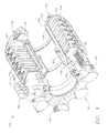
- FIG. 1 is a cut-away view of a typical aircraft brake 100 and, in particular, a brake having friction material components made of carbon-carbon composite material.
- the aircraft brake 100 includes a piston housing 104 having a plurality of hydraulic pistons 106 located about the circumference of the piston housing 104, hydraulic fittings 109 for communication with a hydraulic brake actuation system (not shown) of an aircraft (not shown), a torque take-out arm 108 for attachment to the landing gear (not shown) of the aircraft, and a plurality of circumferentially spaced bolts 110 attaching the piston housing 104 to a torque tube120.
- Torque tube 120 includes axially-extending splines 126 and extends horizontally from the piston housing 104 to a backing plate 124. Located about the torque tube 120 and between the pistons 106 and the backing plate 124, are a plurality of friction material discs constituting the heat stack or brake disc assembly 140 of the aircraft brake 100.
- the friction material discs of the brake disc assembly 140 include six rotor discs 160, five stator discs 170, a pressure plate disc 180, and a backing plate disc 190.
- the rotor discs 160 include a plurality of spaced-apart slots 166 in their outer circumference.
- the spaced-apart slots 166 receive drive keys (not shown) either attached to or made an integral part of the aircraft wheel (not shown) at a wheel well opening so that the rotor discs 160 are connected non-rotatably with the wheel.
- the stator discs 170 include at their inner diameter a plurality of spaced-apart slots 176
- the pressure plate disc 180 includes at its inner diameter a plurality spaced-apart slots 186
- the backing plate disc 190 includes at its inner diameter a plurality of spaced-apart slots 196.
- the spaced-apart slots 176, 186, and 196 receive the splines 126 of the torque tube 120 so that the stator discs 170, the pressure plate disc 180 and the backing plate disc 190 are attached non-rotatably to the torque tube 120.
- the aircraft brake (the assembled piston housing 104, the torque tube120, and the brake disc assembly 140) is mounted to an axle (not shown) of an aircraft landing gear (not shown), the torque take-out arm 108 is connected to the landing gear, and the piston housing 104 is connected via the fittings 109 to the hydraulic brake actuation system (not shown) of the aircraft.
- hydraulic brake fluid is pressurized to cause the hydraulic pistons 106 to extend from the piston housing 104 and squeeze together the spinning rotor discs 160 and the stationary stator discs 170 between the stationary pressure plate disc 180 and the stationary backing plate disc 190, thereby causing the spinning rotor discs 160 and attached wheel to decelerate and slow down the aircraft until it is brought to a stop.
- the illustrated aircraft brake 100 can also be an electric aircraft brake that utilizes electro-mechanical actuators instead of the hydraulic pistons 106 and an electrical actuation system instead of the hydraulic brake actuation system, as is well known within the aircraft industry.
- the pressure plate disc 180, the rotor discs 160, the stator discs 170, and the backing plate disc 190 of the brake disc assembly 140 are made of carbon-carbon composite material. Repeated actuation of the aircraft brake 100 causes the brake disc assembly 140 to wear until the pressure plate disc 180, the rotor discs 160, the stator discs 170, and the backing plate disc 190 must be replaced with similar discs that have the thicknesses of unworn discs. In FIG. 1 for example, the rotor discs 160 and the stator discs 170 may have an initial, unused thickness of approximately 2.02 cm (0.800 inch).
- the illustrated brake disc assembly 140 of the aircraft brake 100 comprises what is well known as a balanced brake disc assembly 140 (e.g., each rotor disc and stator disc has essentially the same thickness).
- a balanced brake disc assembly 140 e.g., each rotor disc and stator disc has essentially the same thickness.
- the brake disc assembly 140 is removed from the aircraft brake 100 and replaced with an overhauled brake disc assembly wherein the rotor discs 160 and the stator discs 170 each have an unworn thickness of approximately 2.02 cm (0.800 inch).
- a well-known brake disc assembly having rotor discs and stator discs with significantly different thicknesses is often called a thick-thin brake disc assembly.
- the thin discs When the thin discs (rotor discs or stator discs) are worn to a thickness necessitating replacement, they are replaced at brake overhaul by new or refurbished thick discs, and the formerly thick discs (rotor discs or stator discs) remain in the overhauled brake disc assembly as worn thin discs and are used for another brake service run.
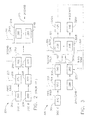
- FIG. 2 illustrates a well-known method 200 of reworking or refurbishing worn carbon-carbon composite brake discs so that the refurbished discs may be used again for braking.
- the method of FIG. 2 enables more carbon-carbon composite material to be used before the brake discs must be discarded because their thicknesses are too small to permit further use for braking.
- the method 200 of FIG. 2 is commonly called a 2-for-1 refurbishment method.
- the new Disc A and the new Disc B are the same type of brake disc, either a stator disc or a rotor disc, and are used in a brake disc assembly of a brake (e.g., the brake disc assembly 140 of FIG. 1 ).
- the brake disc assembly may be either a balanced brake disc assembly having the stator and rotor discs with essentially the same thickness, or a thick-thin brake disc assembly having the rotor and stator discs with substantially different thicknesses.
- both the new Disc A and the new Disc B have an initial thickness of about 2.02 cm (0.800 inch) (blocks 202 and 204) when usage in the brake begins.
- the use of the Discs A and B in the brake disc assembly of the brake for a service run or predetermined period of braking is commonly called a braking tour, and is indicated in FIG. 2 by First Tour 203.
- the Disc A and Disc B each have a worn thickness of about 1.46 cm (0.572 inch) (blocks 206 and 208) and are refurbished by machining each of the Discs A and B to a thickness of about 1.01 cm (0.400 inch) (blocks 210 and 212).
- the refurbished Discs A and B are then fastened together by either mechanical fasteners or by bonding of the Discs A and B to provide a Combined Disc 213 having a thickness of about 2.02 cm (0.800 inch).
- the Combined Disc 213 may then be used in the brake for a Second Tour 211.
- a resulting Worn Disc 215 includes a worn refurbished Disc A (block 214A) and a worn refurbished Disc B (block 214B) each having a worn thickness of about 0.73 cm (0.286 inch) (block 214).
- the individual worn refurbished Discs A and B (blocks 214A and 214B) of the Worn Disc 215 cannot be machined to a smaller thickness and reused in method 200 because such thinner discs may not, even when combined together, have sufficient structural strength, thermal capability, or dynamic stability to meet aircraft braking requirements.
- the worn refurbished Discs A and S (blocks 214A and 214B) of the Worn Disc 215 have to be discarded after only two tours of braking.
- the amount of friction material of a brake disc, either the new Disc A or the new Disc B, used during the First Tour 203 and the Second Tour 211 of braking can be calculated by subtracting the worn disc thickness from the preceding new or refurbished disc thickness.
- FIG. 3 is a representative flow chart of an example method 300 for the utilization of a worn refurbished brake disc to extend the braking life of a brake disc and, in particular, a carbon-carbon composite brake disc.
- the Disc C is a new or unworn brake disc having a first thickness of about 2.02 cm (0.800 inch) (block 302) when it is placed into a brake disc assembly of a brake (i.e., the brake disc assembly 140 and the brake 100 of FIG. 1 ) for a First Tour 303 of braking.
- the worn Disc C has a first worn thickness of about 1.46 cm (0.572 inch) (block 304) and is refurbished by machining the worn Disc C to a first machined thickness of about 1.36 cm (0.540 inch) to produce a first refurbished disc (block 306).
- the material of a carbon-carbon composite brake disc is essentially a ceramic, the disc material typically is machined away by a cutting tool. However, as is well known by persons of ordinary skill in the art, other machining devices may be used.
- a water jet cutter or a laser cutter and all such cutting devices or their equivalents may be used to machine the disc material in the example method 304 of FIG. 3 .
- the twice refurbished disc (block 330) may be machined from discs available from: either a disc that is a product (block 320A) of the example method 300 of FIG. 3 (as disclosed below) or a worn refurbished disc from the previously described 2-for- 1 method 200 illustrated in FIG. 2 , which produces the worn refurbished discs of block 214A and 214B.
- a worn first refurbished disc (block 320A of block 320) having a second worn thickness of about 1.08 cm (about 0.426 inch) may be machined to a second machined thickness of about 0.66 cm (0.260 inch) to produce the second refurbished disc (block 330) for combination with the first refurbished disc of block 306.
- first refurbished disc (block 306) and the twice refurbished disc (block 330) have a combined thickness of about 2.02 cm (0.800 inch) to produce the first combination of discs 307.
- the first combination of discs 307 is then placed in a brake disc assembly of the brake (i.e., the brake disc assembly 140 of the brake 100) for a second service run of braking (a Second Tour 305).
- the worn first combination of discs 307 includes a worn first refurbished disc (block 320A) having a worn thickness of about 1.08 cm (0.426 inch) and a worn second refurbished disc (block 320B) having a worn thickness of about 0.38 cm (0.146 inch). Because the worn twice refurbished disc (block 320B) is too thin to be machined or refurbished to a usable thickness, it is discarded.
- the worn first refurbished disc (block 320A) has a worn thickness of about 1.08 cm (0.426 inch) that is then machined to a thickness of about 0.66 cm (0.260 inch) to provide a twice refurbished disc (block 330) for combination with a first refurbished disc (block 306) to produce a second combination of discs 307A having a combined thickness of about 2.02 cm (0.800 inch).
- the twice refurbished disc of block 330 is part of the second combination of discs 307A placed in the brake disc assembly of the brake for braking.
- the twice refurbished disc of Block 330 is utilized for its Third Tour 309 of braking, which also constitutes the Second Tour 305 of braking for the first refurbished disc (block 306) of the second combination of discs 307A.
- a worn first refurbished disc (block 320A) is not available, then a new disc having a thickness of about 0.66 cm (0.260 inch), or a disc having a thickness greater than 0.66 cm (0.260 inch) that is then machined to the thickness of about 0.66 cm (0.260 inch) can be used to provide a substitute disc for block 330 of method the example 300.
- the worn second combination of discs 307A includes a worn first refurbished disc (block 320A) having a worn thickness of about 1.08 cm (0.426 inch) and a worn second refurbished disc (block 3208) having a worn thickness of about 0.37 cm (0.146 inch).
- the worn second refurbished disc (block 320B) is too thin to be machined or refurbished to a usable thickness, it is discarded, and the worn first refurbished disc (block 320A) is machined to the second machined thickness to produce a twice refurbished disc (block 330) for use in its Third Tour 309 of braking as part of a second combination of discs 307A which includes the first refurbished disc of block 306,
- the amount of the friction material of the Disc C used during the three tours of braking can be calculated by subtracting a worn disc thickness from the preceding new or refurbished disc thickness.
- the worn Disc C was then machined to a first refurbished thickness of about 1.36 cm (0.540 inch) (block 306) before it was combined with the twice refurbished disc of block 330 to produce the first combination of discs 307 used in the Second Tour 305 of braking.
- the worn first refurbished disc (block 320A) was then machined to a second machined thickness of about 0.66 cm (0.260 inch) to produce the twice refurbished disc of block 330.
- the twice refurbished disc of block 330 was then combined with another first refurbished disc of block 306 to produce the second combination of discs 307A for use in the Third Tour 309 of braking.
- the total friction material of the Disc C used during the three Tours (the First Tour 303, the Second Tour 305, and the Third Tour 309) of braking was 1.12 cm (0.456 inch) (i.e.
- the example method 300 of FIG. 3 provides the utilization of 1.12 cm (0.456 inch) of friction material of a brake disc for three tours of braking as compared to the utilization of 0.87 cm (0.342 inch) of friction material of a brake disc for two tours of braking in the 2-for-1 method 200 of FIG. 2 .
- the example method 300 enables an additional 0.28 cm (0. 114 inch) of friction material (i.e., an increase of 33.3%) to be utilized.
- a balanced brake disc assembly can have overall fewer part numbers than the overall part numbers used with a thick-thin brake disc assembly, which can reduce the number of parts to be tracked by an aircraft operator.
- the reuse of the refurbished brake discs in the same type of balanced brake disc assembly minimizes any effects upon the thermal balance of the brake disc assembly.
Landscapes
- Engineering & Computer Science (AREA)
- General Engineering & Computer Science (AREA)
- Mechanical Engineering (AREA)
- Braking Arrangements (AREA)
Description
- This disclosure relates generally to a method to utilize worn refurbished brake material and, more particularly, to the utilization of worn refurbished carbon-carbon composite brake material.
- The use of carbon-carbon composite brake discs in aircraft brakes, which have been referred to as carbon brakes, is well known in the aerospace industry. Carbon-carbon composite brake discs are manufactured by aircraft wheel and brake manufacturers using a variety of manufacturing methods, which generally require lengthy fabrication and densification methods. In recent years, aircraft manufacturers have increasingly specified the use of such carbon-carbon composite brake discs for brakes designed for use with new aircraft models. Typically, the greater the service life of carbon-carbon composite brake discs (e.g., the more service runs in which the brake discs can be utilized), the more the overall cost of utilizing carbon brakes in an aircraft is reduced. Therefore, it is highly desirable to use as much of the carbon-carbon composite material of a carbon-carbon composite brake disc before a worn brake disc must be discarded because its worn thickness is too thin to permit reuse.
-
US-B-3712427 discloses a brake disk assembly comprising graphite and /or carbon disks with removable wear faces. - According to the present invention there is provided a method to utilize a brake disc for braking wherein the brake disc is one of a group of rotor discs and a group of stator discs, the method comprising:
- using a brake disc having a first thickness for braking to provide a worn disc having a first worn thickness;
- machining the worn disc to a once machined thickness to provide a once refurbished disc;
- combining the once refurbished disc with a twice refurbished disc to provide a first combined disc having a first combined thickness substantially the same as the first thickness;
- using the first combined disc for braking to provide a worn first combined disc including a worn once refurbished disc having a second worn thickness;
- machining the worn once refurbished disc to a second machined thickness to provide another twice refurbished disc;
- combining the other twice refurbished disc with another once refurbished disc to provide a second combined disc having a second combined thickness substantially the same as the first thickness; and
- using the second combined disc for braking to provide a worn second combined disc.
-
FIG. 1 is a cut-away perspective illustration of an example aircraft brake having a brake disc assembly with carbon-carbon composite brake discs. -
FIG. 2 is a representative flow diagram of a known 2-for-1 carbon-carbon composite brake disc refurbishment process. -
FIG. 3 is a representative flow diagram of an example method to utilize worn refurbished brake material that enables a brake disc to be utilized for three brake service runs. - In general, the example method and brake disc assembly to utilize worn refurbished brake material described herein may be applied to brake discs that are manufactured from various materials and by various manufacturing methods. Additionally, while the examples described herein are described in connection with aircraft applications in the aerospace industry, the examples described herein may be more generally applicable to a variety of braking applications in different industries.
-
FIG. 1 is a cut-away view of atypical aircraft brake 100 and, in particular, a brake having friction material components made of carbon-carbon composite material. Theaircraft brake 100 includes apiston housing 104 having a plurality ofhydraulic pistons 106 located about the circumference of thepiston housing 104,hydraulic fittings 109 for communication with a hydraulic brake actuation system (not shown) of an aircraft (not shown), a torque take-outarm 108 for attachment to the landing gear (not shown) of the aircraft, and a plurality of circumferentially spacedbolts 110 attaching thepiston housing 104 to a torque tube120. -
Torque tube 120 includes axially-extendingsplines 126 and extends horizontally from thepiston housing 104 to abacking plate 124. Located about thetorque tube 120 and between thepistons 106 and thebacking plate 124, are a plurality of friction material discs constituting the heat stack orbrake disc assembly 140 of theaircraft brake 100. The friction material discs of thebrake disc assembly 140 include sixrotor discs 160, fivestator discs 170, apressure plate disc 180, and abacking plate disc 190. - As is well known in the aircraft wheel and brake industry, the
rotor discs 160 include a plurality of spaced-apart slots 166 in their outer circumference. The spaced-apart slots 166 receive drive keys (not shown) either attached to or made an integral part of the aircraft wheel (not shown) at a wheel well opening so that therotor discs 160 are connected non-rotatably with the wheel. In a similar manner, thestator discs 170 include at their inner diameter a plurality of spaced-apart slots 176, thepressure plate disc 180 includes at its inner diameter a plurality spaced-apart slots 186, and thebacking plate disc 190 includes at its inner diameter a plurality of spaced-apart slots 196. The spaced-apart slots splines 126 of thetorque tube 120 so that thestator discs 170, thepressure plate disc 180 and thebacking plate disc 190 are attached non-rotatably to thetorque tube 120. - In operation, the aircraft brake (the assembled
piston housing 104, the torque tube120, and the brake disc assembly 140) is mounted to an axle (not shown) of an aircraft landing gear (not shown), the torque take-outarm 108 is connected to the landing gear, and thepiston housing 104 is connected via thefittings 109 to the hydraulic brake actuation system (not shown) of the aircraft. When an aircraft operator actuates a brake pedal of the aircraft or when the brakes are operated automatically by the aircraft's hydraulic brake actuation system, hydraulic brake fluid is pressurized to cause thehydraulic pistons 106 to extend from thepiston housing 104 and squeeze together thespinning rotor discs 160 and thestationary stator discs 170 between the stationarypressure plate disc 180 and the stationarybacking plate disc 190, thereby causing thespinning rotor discs 160 and attached wheel to decelerate and slow down the aircraft until it is brought to a stop. Persons of ordinary skill understand that the illustratedaircraft brake 100 can also be an electric aircraft brake that utilizes electro-mechanical actuators instead of thehydraulic pistons 106 and an electrical actuation system instead of the hydraulic brake actuation system, as is well known within the aircraft industry. - In the illustrated aircraft brake100 of
FIG. 1 , thepressure plate disc 180, therotor discs 160, thestator discs 170, and thebacking plate disc 190 of thebrake disc assembly 140 are made of carbon-carbon composite material. Repeated actuation of theaircraft brake 100 causes thebrake disc assembly 140 to wear until thepressure plate disc 180, therotor discs 160, thestator discs 170, and thebacking plate disc 190 must be replaced with similar discs that have the thicknesses of unworn discs. InFIG. 1 for example, therotor discs 160 and thestator discs 170 may have an initial, unused thickness of approximately 2.02 cm (0.800 inch). Thus, the illustratedbrake disc assembly 140 of theaircraft brake 100 comprises what is well known as a balanced brake disc assembly 140 (e.g., each rotor disc and stator disc has essentially the same thickness). When therotor discs 160 and thestator discs 170 have been worn to a thickness of approximately 1.46 cm (0.572 inch), thebrake disc assembly 140 is removed from theaircraft brake 100 and replaced with an overhauled brake disc assembly wherein therotor discs 160 and thestator discs 170 each have an unworn thickness of approximately 2.02 cm (0.800 inch). Although not illustrated herein, a well-known brake disc assembly having rotor discs and stator discs with significantly different thicknesses is often called a thick-thin brake disc assembly. When the thin discs (rotor discs or stator discs) are worn to a thickness necessitating replacement, they are replaced at brake overhaul by new or refurbished thick discs, and the formerly thick discs (rotor discs or stator discs) remain in the overhauled brake disc assembly as worn thin discs and are used for another brake service run. -
FIG. 2 illustrates a well-knownmethod 200 of reworking or refurbishing worn carbon-carbon composite brake discs so that the refurbished discs may be used again for braking. The method ofFIG. 2 enables more carbon-carbon composite material to be used before the brake discs must be discarded because their thicknesses are too small to permit further use for braking. Themethod 200 ofFIG. 2 is commonly called a 2-for-1 refurbishment method. InFIG. 2 , the new Disc A and the new Disc B are the same type of brake disc, either a stator disc or a rotor disc, and are used in a brake disc assembly of a brake (e.g., thebrake disc assembly 140 ofFIG. 1 ). The brake disc assembly may be either a balanced brake disc assembly having the stator and rotor discs with essentially the same thickness, or a thick-thin brake disc assembly having the rotor and stator discs with substantially different thicknesses. To illustrate the refurbishment process ormethod 200 ofFIG. 2 , both the new Disc A and the new Disc B have an initial thickness of about 2.02 cm (0.800 inch) (blocks 202 and 204) when usage in the brake begins. The use of the Discs A and B in the brake disc assembly of the brake for a service run or predetermined period of braking is commonly called a braking tour, and is indicated inFIG. 2 by First Tour 203. After the brake disc assembly of the brake has worn to a predetermined overall combined thickness for all of the rotors and stators (i.e., at the completion of the First Tour 203), the Disc A and Disc B each have a worn thickness of about 1.46 cm (0.572 inch) (blocks 206 and 208) and are refurbished by machining each of the Discs A and B to a thickness of about 1.01 cm (0.400 inch) (blocks 210 and 212). The refurbished Discs A and B are then fastened together by either mechanical fasteners or by bonding of the Discs A and B to provide a CombinedDisc 213 having a thickness of about 2.02 cm (0.800 inch). The CombinedDisc 213 may then be used in the brake for aSecond Tour 211. After the brake disc assembly of the brake has again worn to the predetermined overall combined thickness for all of the rotors and stators (i.e., at the completion of the Second Tour 211), a resultingWorn Disc 215 includes a worn refurbished Disc A (block 214A) and a worn refurbished Disc B (block 214B) each having a worn thickness of about 0.73 cm (0.286 inch) (block 214). The individual worn refurbished Discs A and B (blocks method 200 because such thinner discs may not, even when combined together, have sufficient structural strength, thermal capability, or dynamic stability to meet aircraft braking requirements. Thus, inFIG. 2 the worn refurbished Discs A and S (blocks Worn Disc 215 have to be discarded after only two tours of braking. - The amount of friction material of a brake disc, either the new Disc A or the new Disc B, used during the
First Tour 203 and the Second Tour 211 of braking can be calculated by subtracting the worn disc thickness from the preceding new or refurbished disc thickness. For example, the new Disc A had a thickness of about 2.02 cm (0.800 inch) (block 202) and after theFirst Tour 203 of braking had a worn thickness of about 1.46 cm (0.572 inch) (block 206); resulting in 2.02 - 1.46 = 0.56 cm (0.800 - 0.572 = 0.228 inch) of friction material used during theFirst Tour 203 of braking for the new, Disc A. The refurbished Disc A (block 210) had a refurbished disc thickness of about 1.01 cm (0.400 inch) and the worn refurbished Disc A (block 214A) had a thickness of about 0.73cm (0.286 inch); resulting in 1.01 - 0.73 = 0.28 cm (0.400 - 0.286 inches = 0.114 inch) of friction material used during theSecond Tour 211 of braking. Thus, the total friction material of the Disc A used during theFirst Tour 203 and theSecond Tour 211 of braking was about 0.87 cm (0.342 inch); 0.58 + 0.29 = 0.87 cm (0.228 + 0.114 = 0.342 inch). -
FIG. 3 is a representative flow chart of anexample method 300 for the utilization of a worn refurbished brake disc to extend the braking life of a brake disc and, in particular, a carbon-carbon composite brake disc. In theexample method 300, the Disc C is a new or unworn brake disc having a first thickness of about 2.02 cm (0.800 inch) (block 302) when it is placed into a brake disc assembly of a brake (i.e., thebrake disc assembly 140 and thebrake 100 ofFIG. 1 ) for aFirst Tour 303 of braking. After the brake disc assembly of the brake has worn to a predetermined overall combined thickness for the rotors and stators (i.e., at the completion of the First Tour 303), the worn Disc C has a first worn thickness of about 1.46 cm (0.572 inch) (block 304) and is refurbished by machining the worn Disc C to a first machined thickness of about 1.36 cm (0.540 inch) to produce a first refurbished disc (block 306). Because the material of a carbon-carbon composite brake disc is essentially a ceramic, the disc material typically is machined away by a cutting tool. However, as is well known by persons of ordinary skill in the art, other machining devices may be used. For example, a water jet cutter or a laser cutter, and all such cutting devices or their equivalents may be used to machine the disc material in theexample method 304 ofFIG. 3 . The first refurbished disc ofblock 306 is then combined with a twice refurbished disc (block 330) to provide a first combination ofdiscs 307 having an overall or combined thickness of about 2.02 cm ( = 1.36 + 0.66) (0.800 inch (= 0.540 + 0.260 inches)) required for braking use. - The twice refurbished disc (block 330) may be machined from discs available from: either a disc that is a product (
block 320A) of theexample method 300 ofFIG. 3 (as disclosed below) or a worn refurbished disc from the previously described 2-for- 1method 200 illustrated inFIG. 2 , which produces the worn refurbished discs ofblock example method 300 ofFIG. 3 , a worn first refurbished disc (block 320A of block 320) having a second worn thickness of about 1.08 cm (about 0.426 inch) may be machined to a second machined thickness of about 0.66 cm (0.260 inch) to produce the second refurbished disc (block 330) for combination with the first refurbished disc ofblock 306. Together the first refurbished disc (block 306) and the twice refurbished disc (block 330) have a combined thickness of about 2.02 cm (0.800 inch) to produce the first combination ofdiscs 307. The first combination ofdiscs 307 is then placed in a brake disc assembly of the brake (i.e., thebrake disc assembly 140 of the brake 100) for a second service run of braking (a Second Tour 305). - After the brake disc assembly of the brake has worn to a predetermined overall combined thickness for all of the rotors and stators (i.e., at the completion of the Second Tour 305), the worn first combination of
discs 307 includes a worn first refurbished disc (block 320A) having a worn thickness of about 1.08 cm (0.426 inch) and a worn second refurbished disc (block 320B) having a worn thickness of about 0.38 cm (0.146 inch). Because the worn twice refurbished disc (block 320B) is too thin to be machined or refurbished to a usable thickness, it is discarded. The worn first refurbished disc (block 320A) has a worn thickness of about 1.08 cm (0.426 inch) that is then machined to a thickness of about 0.66 cm (0.260 inch) to provide a twice refurbished disc (block 330) for combination with a first refurbished disc (block 306) to produce a second combination ofdiscs 307A having a combined thickness of about 2.02 cm (0.800 inch). Thus, the twice refurbished disc ofblock 330 is part of the second combination ofdiscs 307A placed in the brake disc assembly of the brake for braking. As a result, the twice refurbished disc ofBlock 330 is utilized for itsThird Tour 309 of braking, which also constitutes theSecond Tour 305 of braking for the first refurbished disc (block 306) of the second combination ofdiscs 307A. - Alternatively, if a worn first refurbished disc (block 320A) is not available, then a new disc having a thickness of about 0.66 cm (0.260 inch), or a disc having a thickness greater than 0.66 cm (0.260 inch) that is then machined to the thickness of about 0.66 cm (0.260 inch) can be used to provide a substitute disc for
block 330 of method the example 300. - After the brake disc assembly of the brake has worn to a predetermined overall combined thickness for the rotors and stators (i.e., the completion of the
Third Tour 309 of braking for the twice refurbished disc of theblock 330 and theSecond Tour 305 of braking for the first refurbished disc of block 306), the worn second combination ofdiscs 307A includes a worn first refurbished disc (block 320A) having a worn thickness of about 1.08 cm (0.426 inch) and a worn second refurbished disc (block 3208) having a worn thickness of about 0.37 cm (0.146 inch). Because the worn second refurbished disc (block 320B) is too thin to be machined or refurbished to a usable thickness, it is discarded, and the worn first refurbished disc (block 320A) is machined to the second machined thickness to produce a twice refurbished disc (block 330) for use in itsThird Tour 309 of braking as part of a second combination ofdiscs 307A which includes the first refurbished disc ofblock 306, - In the
example method 300 ofFIG. 3 , the amount of the friction material of the Disc C used during the three tours of braking can be calculated by subtracting a worn disc thickness from the preceding new or refurbished disc thickness. For example, the new Disc C had a thickness of 2.02 cm (0.800 inch) (block 302) and after theFirst Tour 303 of braking had a first worn thickness of about 1.46 cm (0.572 inch) (Block 304), resulting in 2.02 - 1.46 = 0.56 cm (0.800 - 0.572 = 0.228 inch) of friction material used during theFirst Tour 303 of braking. The worn Disc C was then machined to a first refurbished thickness of about 1.36 cm (0.540 inch) (block 306) before it was combined with the twice refurbished disc ofblock 330 to produce the first combination ofdiscs 307 used in theSecond Tour 305 of braking. After completion of theSecond Tour 305, the worn first refurbished disc (block 320A) had a second worn thickness of about 1.08 cm (0.426 inch), resulting in 1.36 - 1.08 = 0.28 cm (0.540 - 0.426 = 0.114 inch) of friction material used during theSecond Tour 305 of braking. The worn first refurbished disc (block 320A) was then machined to a second machined thickness of about 0.66 cm (0.260 inch) to produce the twice refurbished disc ofblock 330. The twice refurbished disc ofblock 330 was then combined with another first refurbished disc ofblock 306 to produce the second combination ofdiscs 307A for use in theThird Tour 309 of braking. After the completion of itsThird Tour 309 of braking, the worn second refurbished disc ofblock 320B had a worn thickness of about 0.38 cm (0.146 inch), resulting in 0.66 - 0.38 = 0.28 cm (0.260 - 0.146 = 0.114 inch) of friction material used during theThird Tour 309 of braking for the Disc G. Thus, the total friction material of the Disc C used during the three Tours (theFirst Tour 303, theSecond Tour 305, and the Third Tour 309) of braking was 1.12 cm (0.456 inch) (i.e. 0.56 cm (0.228 inch) + 0.28 cm (0.114 inch) + 0.28 cm (0.114 inch) = 1.12 cm (0.456 inch). In this manner, theexample method 300 ofFIG. 3 provides the utilization of 1.12 cm (0.456 inch) of friction material of a brake disc for three tours of braking as compared to the utilization of 0.87 cm (0.342 inch) of friction material of a brake disc for two tours of braking in the 2-for-1method 200 ofFIG. 2 . As can be seen from the foregoing, theexample method 300 enables an additional 0.28 cm (0. 114 inch) of friction material (i.e., an increase of 33.3%) to be utilized. - It is economically desirable to increase the utilization of the friction material of carbon-carbon composite brake discs, and an increase of 33.3% in the utilization of carbon-carbon composite friction material for braking is a significant improvement that can contribute significantly to reducing an aircraft operator's cost of operating an aircraft equipped with brakes having carbon-carbon composite brake discs. Although the example method in
FIG. 3 can be used with either a balanced brake disc assembly or a thick-thin brake disc assembly, a balanced brake disc assembly can have overall fewer part numbers than the overall part numbers used with a thick-thin brake disc assembly, which can reduce the number of parts to be tracked by an aircraft operator. In addition, the reuse of the refurbished brake discs in the same type of balanced brake disc assembly minimizes any effects upon the thermal balance of the brake disc assembly. - An example method and brake disc assembly are described with reference to the flowchart illustrated in
FIG. 3 . However, persons of ordinary skill in the art will readily appreciate that other methods of implementing the example method may alternatively be used. For example, the order of execution of the blocks may be changed, and/or some of the blocks described may be changed, eliminated, or combined. - Although certain example methods and apparatus have been described herein, these do not limit the scope of coverage of this patent which is limited only by the appended claims.
Claims (5)
- A method to utilize a brake disc for braking wherein the brake disc is one of a group of rotor discs and a group of stator discs, the method comprising :using (303) a brake disc (302) having a first thickness for braking to provide a worn disc (304) having a first worn thickness;machining the worn disc (304) to a once machined thickness to provide a once refurbished disc (306);combining the once refurbished disc (306) with a twice refurbished disc (330) to provide a first combined disc (307) having a first combined thickness substantially the same as the first thickness;using (305) the first combined disc (307) for braking to provide a worn first combined disc (320) including a worn once refurbished disc (320A) having a second worn thickness;machining the worn once refurbished disc (320A) to a second machined thickness to provide another twice refurbished disc (330);combining the other twice refurbished disc (330) with another once refurbished disc (306) to provide a second combined disc (307A) having a second combined thickness substantially the same as the first thickness; andusing (309) the second combined disc (307A) for braking to provide a worn second combined disc (320A/320B).
- A method as claimed in claim 1, wherein the worn first combined disc (320) has a first worn combined thickness and the worn second combined disc (320A/320B) has a second worn combined thickness substantially equal to the first worn combined thickness.
- A method as claimed in claim 1, wherein the twice refurbished disc (330) comprises at least one of a machined worn refurbished disc (214A/214B/330) and the other twice refurbished disc (330).
- A method as claimed in claim 3, further comprising discarding the machined worn refurbished disc (214A/215B/330) of the worn first combined disc (320).
- A method as claimed in claim 1, further comprising discarding the other twice refurbished disc (330) of the worn second combined disc (320A/320B).
Applications Claiming Priority (1)
| Application Number | Priority Date | Filing Date | Title |
|---|---|---|---|
| US11/345,468 US7900751B2 (en) | 2006-02-01 | 2006-02-01 | Method and brake disc assembly to utilize worn refurbished brake material |
Publications (2)
| Publication Number | Publication Date |
|---|---|
| EP1816369A1 EP1816369A1 (en) | 2007-08-08 |
| EP1816369B1 true EP1816369B1 (en) | 2009-05-06 |
Family
ID=37951754
Family Applications (1)
| Application Number | Title | Priority Date | Filing Date |
|---|---|---|---|
| EP07101548A Not-in-force EP1816369B1 (en) | 2006-02-01 | 2007-02-01 | Method to utilize worn refurbished brake disc material |
Country Status (3)
| Country | Link |
|---|---|
| US (1) | US7900751B2 (en) |
| EP (1) | EP1816369B1 (en) |
| DE (1) | DE602007001041D1 (en) |
Families Citing this family (13)
| Publication number | Priority date | Publication date | Assignee | Title |
|---|---|---|---|---|
| US8662277B2 (en) | 2011-12-22 | 2014-03-04 | Fairfield Manufacturing Company, Inc. | Planetary gearbox with integral service brake |
| FR2989137B1 (en) | 2012-04-06 | 2014-05-16 | Messier Bugatti Dowty | METHOD OF USING AND RENOVATING A DISC OF A DISC STACK OF A BRAKE OF A VEHICLE |
| US9315261B2 (en) * | 2013-06-26 | 2016-04-19 | Goodrich Corporation | Keyed brake disk assembly |
| US9194447B2 (en) | 2013-11-11 | 2015-11-24 | Goodrich Corporation | Keyed brake disk assembly |
| FR3013412B1 (en) * | 2013-11-21 | 2015-12-25 | Messier Bugatti Dowty | METHOD FOR RENOVATING AND USING REAR STATOR BRAKE DISC BRAKES, ASSEMBLED DISK AND CORRESPONDING DISC BATTERY. |
| US9429227B2 (en) | 2014-02-19 | 2016-08-30 | Fairfield Manufacturing Company, Inc. | Planetary gearbox with integral service brake |
| KR101476616B1 (en) | 2014-02-26 | 2014-12-24 | 데크컴퍼지트 주식회사 | Apparatus for testing brake disk of aircraft |
| US10274034B2 (en) | 2017-07-12 | 2019-04-30 | Goodrich Corporation | Wear liner with integrated torque button |
| US10309468B2 (en) * | 2017-10-20 | 2019-06-04 | Goodrich Corporation | Torque plate barrel having blended barrel support pedestal |
| US10941823B2 (en) | 2017-11-27 | 2021-03-09 | Goodrich Corporation | Segmented wear liner |
| US10724591B2 (en) * | 2017-11-27 | 2020-07-28 | Goodrich Corporation | Brake assembly with disks of variable thickness and methods for disk reuse |
| US12540651B2 (en) | 2023-09-05 | 2026-02-03 | Goodrich Corporation | Ceramic particulate coating for wear improvement |
| US12577998B2 (en) * | 2023-09-26 | 2026-03-17 | Goodrich Corporation | Material life extension for refurbished 2-for-1 carbon brakes via ceramic solutions |
Family Cites Families (19)
| Publication number | Priority date | Publication date | Assignee | Title |
|---|---|---|---|---|
| US3712427A (en) | 1970-11-05 | 1973-01-23 | Goodyear Tire & Rubber | Graphite and/or carbon disk with removable wear faces |
| US3956548A (en) | 1973-12-20 | 1976-05-11 | Goodyear Aerospace Corporation | Duo material carbon composite brake disk |
| US4613017A (en) | 1984-07-02 | 1986-09-23 | The B. F. Goodrich Company | Disk brake and method of assembly |
| US4742895A (en) * | 1984-07-02 | 1988-05-10 | The B. F. Goodrich Company | Disk brake assembly |
| GB8813518D0 (en) | 1988-06-08 | 1988-07-13 | Dunlop Ltd | Improvements in multi-disc brakes |
| US5509507A (en) * | 1989-06-01 | 1996-04-23 | Dunlop Limited A British Company | Multi-disc brakes |
| US4982818A (en) | 1989-10-17 | 1991-01-08 | Allied-Signal Inc. | Cyclic brake disc overhaul technique and structure |
| US5099960A (en) * | 1990-07-27 | 1992-03-31 | Aircraft Braking Systems Corp. | Composite brake disk and method of extending the braking service life thereof |
| US5143184A (en) * | 1991-02-14 | 1992-09-01 | Allied-Signal Inc. | Carbon composite brake disc with positive vibration damping |
| GB2257212B (en) * | 1991-07-02 | 1995-03-15 | Aircraft Braking Systems Corp | Thermally balanced brake disc stack |
| US5779006A (en) | 1995-05-24 | 1998-07-14 | The B. F. Goodrich Company | Composite friction disk having replaceable wear faces |
| US5769185A (en) | 1995-05-25 | 1998-06-23 | Aircraft Braking Systems Corporation | Carbon brake disc structures and method of making same |
| US5551534A (en) * | 1995-06-05 | 1996-09-03 | Aircraft Braking Systems Corp. | Pressure balanced brake stack |
| FR2755094B1 (en) * | 1996-10-31 | 1998-11-27 | Messier Bugatti | ARRANGEMENT OF CARBON BRAKE DISCS FOR AN AIRCRAFT BRAKE UNIT, AND METHOD OF ASSEMBLING DISCS ACCORDING TO SUCH ARRANGEMENT |
| US7168528B1 (en) * | 1999-05-11 | 2007-01-30 | Goodrich Corporation | Three run disk brake stack and method of assembly |
| US6340075B1 (en) | 1999-11-24 | 2002-01-22 | The B. F. Goodrich Company | Three run disk brake stack and method of assembly |
| US7090057B2 (en) | 2001-06-04 | 2006-08-15 | Honeywell International Inc. | Composite friction disc with structural core and refurbishable lining elements |
| US7104366B2 (en) * | 2002-12-11 | 2006-09-12 | Honeywell International | Method of increasing friction material utilization for carbon brakes |
| GB2403989B (en) | 2003-07-15 | 2006-06-14 | Dunlop Aerospace Ltd | Composite article |
-
2006
- 2006-02-01 US US11/345,468 patent/US7900751B2/en not_active Expired - Fee Related
-
2007
- 2007-02-01 EP EP07101548A patent/EP1816369B1/en not_active Not-in-force
- 2007-02-01 DE DE602007001041T patent/DE602007001041D1/en active Active
Also Published As
| Publication number | Publication date |
|---|---|
| EP1816369A1 (en) | 2007-08-08 |
| DE602007001041D1 (en) | 2009-06-18 |
| US20070175710A1 (en) | 2007-08-02 |
| US7900751B2 (en) | 2011-03-08 |
Similar Documents
| Publication | Publication Date | Title |
|---|---|---|
| EP1816369A1 (en) | Method and brake disc assembly to utilize worn refurbished brake material | |
| EP1826447B1 (en) | Method and brake disc with composite insert member | |
| EP1930618B1 (en) | Methods and brake disc assemblies to increase the use of friction material | |
| US5323880A (en) | Multi-disc brakes | |
| EP1103738B1 (en) | Disc brake stack replaceable in three runs and method of assembly | |
| US4613017A (en) | Disk brake and method of assembly | |
| EP3187746A1 (en) | Plate assemblies including floating wear linings for multi-disk brake system and methods for reducing vibration in a multi-disk brake system | |
| US7104366B2 (en) | Method of increasing friction material utilization for carbon brakes | |
| EP2126398B1 (en) | Braking | |
| EP1052422B1 (en) | Disk brake stack replaceable in three runs and method of assembly | |
| US5509507A (en) | Multi-disc brakes | |
| EP4386229B1 (en) | Multiple stiffness brake assembly | |
| CN114750934A (en) | Wheel and brake assembly with mechanical stop | |
| US11821478B2 (en) | Brake assembly with disks of variable thickness and methods for disk reuse | |
| EP3712457B1 (en) | Segmented rivetless wear liner with structural carbon or ceramic core | |
| EP3715663B1 (en) | Segmented rivetless wear liner with structural carbon or ceramic core | |
| US12590615B2 (en) | Brake disc system |
Legal Events
| Date | Code | Title | Description |
|---|---|---|---|
| PUAI | Public reference made under article 153(3) epc to a published international application that has entered the european phase |
Free format text: ORIGINAL CODE: 0009012 |
|
| AK | Designated contracting states |
Kind code of ref document: A1 Designated state(s): AT BE BG CH CY CZ DE DK EE ES FI FR GB GR HU IE IS IT LI LT LU LV MC NL PL PT RO SE SI SK TR |
|
| AX | Request for extension of the european patent |
Extension state: AL BA HR MK YU |
|
| 17P | Request for examination filed |
Effective date: 20080128 |
|
| 17Q | First examination report despatched |
Effective date: 20080305 |
|
| AKX | Designation fees paid |
Designated state(s): DE FR GB |
|
| GRAP | Despatch of communication of intention to grant a patent |
Free format text: ORIGINAL CODE: EPIDOSNIGR1 |
|
| RTI1 | Title (correction) |
Free format text: METHOD TO UTILIZE WORN REFURBISHED BRAKE DISC MATERIAL |
|
| GRAS | Grant fee paid |
Free format text: ORIGINAL CODE: EPIDOSNIGR3 |
|
| GRAA | (expected) grant |
Free format text: ORIGINAL CODE: 0009210 |
|
| AK | Designated contracting states |
Kind code of ref document: B1 Designated state(s): DE FR GB |
|
| REG | Reference to a national code |
Ref country code: GB Ref legal event code: FG4D |
|
| REF | Corresponds to: |
Ref document number: 602007001041 Country of ref document: DE Date of ref document: 20090618 Kind code of ref document: P |
|
| PLBE | No opposition filed within time limit |
Free format text: ORIGINAL CODE: 0009261 |
|
| STAA | Information on the status of an ep patent application or granted ep patent |
Free format text: STATUS: NO OPPOSITION FILED WITHIN TIME LIMIT |
|
| 26N | No opposition filed |
Effective date: 20100209 |
|
| PGFP | Annual fee paid to national office [announced via postgrant information from national office to epo] |
Ref country code: DE Payment date: 20110228 Year of fee payment: 5 |
|
| REG | Reference to a national code |
Ref country code: DE Ref legal event code: R119 Ref document number: 602007001041 Country of ref document: DE Effective date: 20120901 |
|
| PG25 | Lapsed in a contracting state [announced via postgrant information from national office to epo] |
Ref country code: DE Free format text: LAPSE BECAUSE OF NON-PAYMENT OF DUE FEES Effective date: 20120901 |
|
| REG | Reference to a national code |
Ref country code: FR Ref legal event code: PLFP Year of fee payment: 10 |
|
| REG | Reference to a national code |
Ref country code: FR Ref legal event code: PLFP Year of fee payment: 11 |
|
| PGFP | Annual fee paid to national office [announced via postgrant information from national office to epo] |
Ref country code: FR Payment date: 20170118 Year of fee payment: 11 |
|
| PGFP | Annual fee paid to national office [announced via postgrant information from national office to epo] |
Ref country code: GB Payment date: 20170126 Year of fee payment: 11 |
|
| GBPC | Gb: european patent ceased through non-payment of renewal fee |
Effective date: 20180201 |
|
| REG | Reference to a national code |
Ref country code: FR Ref legal event code: ST Effective date: 20181031 |
|
| PG25 | Lapsed in a contracting state [announced via postgrant information from national office to epo] |
Ref country code: FR Free format text: LAPSE BECAUSE OF NON-PAYMENT OF DUE FEES Effective date: 20180228 Ref country code: GB Free format text: LAPSE BECAUSE OF NON-PAYMENT OF DUE FEES Effective date: 20180201 |
|
| P01 | Opt-out of the competence of the unified patent court (upc) registered |
Effective date: 20230525 |