EP1816317A2 - Turbocharger with variable nozzle - Google Patents
Turbocharger with variable nozzle Download PDFInfo
- Publication number
- EP1816317A2 EP1816317A2 EP07001398A EP07001398A EP1816317A2 EP 1816317 A2 EP1816317 A2 EP 1816317A2 EP 07001398 A EP07001398 A EP 07001398A EP 07001398 A EP07001398 A EP 07001398A EP 1816317 A2 EP1816317 A2 EP 1816317A2
- Authority
- EP
- European Patent Office
- Prior art keywords
- turbine
- variable nozzle
- bearing housing
- housing
- radial
- Prior art date
- Legal status (The legal status is an assumption and is not a legal conclusion. Google has not performed a legal analysis and makes no representation as to the accuracy of the status listed.)
- Granted
Links
Images


Classifications
-
- F—MECHANICAL ENGINEERING; LIGHTING; HEATING; WEAPONS; BLASTING
- F02—COMBUSTION ENGINES; HOT-GAS OR COMBUSTION-PRODUCT ENGINE PLANTS
- F02B—INTERNAL-COMBUSTION PISTON ENGINES; COMBUSTION ENGINES IN GENERAL
- F02B37/00—Engines characterised by provision of pumps driven at least for part of the time by exhaust
- F02B37/12—Control of the pumps
- F02B37/22—Control of the pumps by varying cross-section of exhaust passages or air passages, e.g. by throttling turbine inlets or outlets or by varying effective number of guide conduits
-
- F—MECHANICAL ENGINEERING; LIGHTING; HEATING; WEAPONS; BLASTING
- F01—MACHINES OR ENGINES IN GENERAL; ENGINE PLANTS IN GENERAL; STEAM ENGINES
- F01D—NON-POSITIVE DISPLACEMENT MACHINES OR ENGINES, e.g. STEAM TURBINES
- F01D17/00—Regulating or controlling by varying flow
- F01D17/10—Final actuators
- F01D17/12—Final actuators arranged in stator parts
- F01D17/14—Final actuators arranged in stator parts varying effective cross-sectional area of nozzles or guide conduits
- F01D17/16—Final actuators arranged in stator parts varying effective cross-sectional area of nozzles or guide conduits by means of nozzle vanes
- F01D17/165—Final actuators arranged in stator parts varying effective cross-sectional area of nozzles or guide conduits by means of nozzle vanes for radial flow, i.e. the vanes turning around axes which are essentially parallel to the rotor centre line
-
- F—MECHANICAL ENGINEERING; LIGHTING; HEATING; WEAPONS; BLASTING
- F01—MACHINES OR ENGINES IN GENERAL; ENGINE PLANTS IN GENERAL; STEAM ENGINES
- F01D—NON-POSITIVE DISPLACEMENT MACHINES OR ENGINES, e.g. STEAM TURBINES
- F01D17/00—Regulating or controlling by varying flow
- F01D17/10—Final actuators
- F01D17/12—Final actuators arranged in stator parts
- F01D17/14—Final actuators arranged in stator parts varying effective cross-sectional area of nozzles or guide conduits
- F01D17/16—Final actuators arranged in stator parts varying effective cross-sectional area of nozzles or guide conduits by means of nozzle vanes
-
- F—MECHANICAL ENGINEERING; LIGHTING; HEATING; WEAPONS; BLASTING
- F01—MACHINES OR ENGINES IN GENERAL; ENGINE PLANTS IN GENERAL; STEAM ENGINES
- F01D—NON-POSITIVE DISPLACEMENT MACHINES OR ENGINES, e.g. STEAM TURBINES
- F01D25/00—Component parts, details, or accessories, not provided for in, or of interest apart from, other groups
- F01D25/16—Arrangement of bearings; Supporting or mounting bearings in casings
- F01D25/162—Bearing supports
-
- F—MECHANICAL ENGINEERING; LIGHTING; HEATING; WEAPONS; BLASTING
- F02—COMBUSTION ENGINES; HOT-GAS OR COMBUSTION-PRODUCT ENGINE PLANTS
- F02B—INTERNAL-COMBUSTION PISTON ENGINES; COMBUSTION ENGINES IN GENERAL
- F02B37/00—Engines characterised by provision of pumps driven at least for part of the time by exhaust
- F02B37/12—Control of the pumps
-
- F—MECHANICAL ENGINEERING; LIGHTING; HEATING; WEAPONS; BLASTING
- F02—COMBUSTION ENGINES; HOT-GAS OR COMBUSTION-PRODUCT ENGINE PLANTS
- F02D—CONTROLLING COMBUSTION ENGINES
- F02D9/00—Controlling engines by throttling air or fuel-and-air induction conduits or exhaust conduits
- F02D9/02—Controlling engines by throttling air or fuel-and-air induction conduits or exhaust conduits concerning induction conduits
-
- F—MECHANICAL ENGINEERING; LIGHTING; HEATING; WEAPONS; BLASTING
- F05—INDEXING SCHEMES RELATING TO ENGINES OR PUMPS IN VARIOUS SUBCLASSES OF CLASSES F01-F04
- F05D—INDEXING SCHEME FOR ASPECTS RELATING TO NON-POSITIVE-DISPLACEMENT MACHINES OR ENGINES, GAS-TURBINES OR JET-PROPULSION PLANTS
- F05D2220/00—Application
- F05D2220/40—Application in turbochargers
-
- F—MECHANICAL ENGINEERING; LIGHTING; HEATING; WEAPONS; BLASTING
- F05—INDEXING SCHEMES RELATING TO ENGINES OR PUMPS IN VARIOUS SUBCLASSES OF CLASSES F01-F04
- F05D—INDEXING SCHEME FOR ASPECTS RELATING TO NON-POSITIVE-DISPLACEMENT MACHINES OR ENGINES, GAS-TURBINES OR JET-PROPULSION PLANTS
- F05D2260/00—Function
- F05D2260/20—Heat transfer, e.g. cooling
- F05D2260/231—Preventing heat transfer
Definitions
- the heat shield plate has a radial-direction outer end portion sandwiched and held between the turbine housing and the bearing housing.
Landscapes
- Engineering & Computer Science (AREA)
- Mechanical Engineering (AREA)
- General Engineering & Computer Science (AREA)
- Chemical & Material Sciences (AREA)
- Combustion & Propulsion (AREA)
- Supercharger (AREA)
Abstract
Description
- The present invention relates to a turbocharger with a variable nozzle, and more particularly to a turbo charger with a variable nozzle having a mechanism capable of suppressing a temperature increase of a compressor side thrust bearing or the like.
- A turbocharger is a supercharger used for a high output of an engine, for example, for a motor vehicle. In the turbocharger, a compressed air is supplied to the engine from a compressor by rotating a turbine impeller by exhaust energy of the engine, and rotating a compressor impeller by an output of the turbine. Accordingly, it is possible to achieve a supercharging state over a natural air supply in the engine.
- In the turbocharger, at the time of low speed revolution of the engine, the turbine hardly works due to a low exhaust flow rate. Accordingly, in the engine capable of operating at a high speed revolution, it takes a long time until the turbine efficiently rotates, so that it is impossible to quickly obtain a turbo effect.
- Accordingly, there has been developed a turbocharger with a variable nozzle (a variable geometry system turbocharger (VGS)) which is efficiently activated even from a low speed revolution range of the engine. The turbocharger with the variable nozzle is structured such that a high output can be obtained even at a time of a low speed revolution, by throttling a small exhaust flow by a movable vane, increasing a speed of the exhaust gas and enlarging a work load of the turbine. The turbocharger with the variable nozzle as mentioned above is described, for example, in
Japanese Examined Patent Publication No. 7-13468 - However, in the turbocharger with the variable nozzle, there is a problem that a temperature of a thrust bearing provided in a compressor side of a bearing housing gets over a critical temperature 250 °C so as to be increased to about 300 °C due to a heat transmission (a heat soak) from a turbine side of the bearing housing to the compressor side, at a time when the engine stops and a pressure oil cooling the bearing housing stops. Meanwhile, the problem mentioned above is not particularly pointed out in the turbocharger with no variable nozzle.
- Accordingly, an object of the present invention is to provide a turbocharger with a variable nozzle having a mechanism capable of maintaining a temperature of a thrust bearing or the like equal to or less than a critical temperature.
- According to the present invention, in order to achieve the object mentioned above, there is provided a turbocharger with a variable nozzle comprising:
- a turbine impeller rotationally driven by an exhaust gas;
- a compressor impeller rotationally driven by the turbine impeller so as to compress an air;
- a shaft coupling the turbine impeller and the compressor impeller;
- a bearing housing rotatably supporting the shaft;
- a turbine housing accommodating the turbine impeller in an inner portion thereof; and
- a variable nozzle mechanism, provided in a compressor impeller side in a radial-direction outer side of the turbine impeller, for adjusting a flow rate of an exhaust gas directed to the turbine impeller,
- wherein the bearing housing has a radially expanded portion that extends to a radial-direction outer side to be coupled to the turbine housing at a radial-direction outer side portion thereof such that the variable nozzle mechanism is accommodated between the turbine housing and the radially expanded portion,
- and a heat shield plate is provided between the variable nozzle mechanism and the radially expanded portion for preventing a heat transmission between the variable nozzle mechanism and the radially expanded portion.
- As for a turbocharger with the variable nozzle, since the variable nozzle mechanism is accommodated between the turbine housing and the bearing housing, the bearing housing has the radially expanded portion extending in the radial direction to be coupled to the radial-direction outer side portion of the turbine housing. Accordingly, the bearing housing is enlarged in size in comparison with the conventional one, and a heat capacity thereof becomes enlarged at that degree. In a hydraulic cooling, it is impossible to sufficiently cool the heat of the radially expanded portion in the bearing housing. However, in the turbocharger with the variable nozzle in accordance with the present invention mentioned above, since the heat shield plate is provided between the variable nozzle mechanism and the radially expanded portion of the bearing housing, in the outer side in the radial direction, it is possible to prevent the heat from being transmitted to the radially expanded portion from the turbine side. In other words, the heat shield plate is provide by providing a space between the variable nozzle mechanism and the radially expanded portion so that radiant heat from high-temperature components at the turbine side can be prevented from transmitting directly to the bearing housing, suppressing a temperature increase in the bearing housing. Accordingly, it is possible to suppress the heating of the radially expanded portion in the bearing housing. As a result, even when the engine stops and supply of the pressure oil for cooling the bearing housing stops, it is possible to maintain the temperature of the thrust bearing or the like equal to or less than the critical temperature.
- According to a preferable aspect of the present invention, the heat shield plate has a radial-direction outer end portion sandwiched and held between the turbine housing and the bearing housing.
- Accordingly, since the heat shield plate can be fixed by only holding the heat shield plate between the turbine housing and the bearing housing, at a time of assembling the turbocharger, it is easy to fix the heat shield plate.
- Further, since the radial-direction outer end portion of the heat shield plate is sandwiched and held between the turbine housing and the bearing housing, the heat shield plate can be attached such that the radial-direction outer end portion of the heat shield plate contacts with the turbine housing and the bearing housing, and such that the other portion of the heat shield plate does not contact with the turbine housing and the bearing housing.
- Accordingly, even if the heat transmission from the turbine side to the radially expanded portion of the bearing housing is generated through the contact portion existing in the radial-direction outer end portion of the heat shield plate, the other portion of the heat shield plate does not contact with the turbine housing and the bearing housing, so that it is possible to minimize an amount of heat transmission from the turbine side to the radially expanded portion through this non-contact portion. Therefore, it is possible to further effectively prevent the heat transmission from the turbine side to the radially expanded portion.
- Further, according to a preferable aspect of the present invention, the heat shield plate is constituted by an annular member having an opening portion in a center thereof, and the bearing housing has a radially contracted portion that protrudes to the turbine housing side from the radially expanded portion to be fitted into the opening portion.
- Accordingly, since it is possible to attach the heat shield plate to the bearing housing by only fitting the radially contracted portion of the bearing housing into the opening portion of the heat shield plate, even at a time of assembling the turbocharger, it is easy to attach the heat shield plate.
- In the present invention mentioned above, since the heat shield plate is provided between the variable nozzle mechanism and the radially expanded portion of the bearing housing, it is possible to prevent the heat transmission from the turbine side to the radially expanded portion. Accordingly, it is possible to suppress the heating of the radially expanded portion in the bearing housing. As a result, even when the engine stops and supply of the pressure oil for cooling the bearing housing stops, it is possible to maintain the temperature of the thrust bearing or the like equal to or less than the critical temperature.
- The other objects and advantageous features of the present invention will be apparent from the following description with reference to the accompanying drawings.
-
- Fig. 1 is a view of an entire structure of a turbocharger with a variable nozzle in accordance with an embodiment of the present invention;
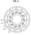
- Fig. 2 is a cross sectional view along a line A-A in Fig. 1, and a view showing a variable nozzle mechanism; and
- Fig. 3 is an enlarged view of a portion surrounded by a broken line B in Fig. 1.
- The description will be given of a preferable embodiment in accordance with the present invention with reference to the accompanying drawings. Meanwhile, the same reference numerals are attached to common portions in each of the drawings, and the repeated description will be omitted.
- Fig. 1 is a cross sectional view in an axial direction of a
turbocharger 10 with a variable nozzle showing an embodiment in accordance with the present invention. Fig. 2 is a view along a line A-A in Fig. 1, and shows avariable nozzle mechanism 12 adjusting a flow rate of an exhaust gas from an engine to a turbine. - A
turbocharger 10 with a variable nozzle shown in Fig. 1 is provided with aturbine impeller 2 rotationally driven by the exhaust gas from the engine, a compressor impeller 4 rotationally driven by a driving force of the turbine so as to supply a compressed air to the engine, ashaft 5 coupling theturbine impeller 2 and the compressor impeller 4, abearing housing 6 rotatably supporting theshaft 5, aturbine housing 7 accommodating theturbine impeller 2 in an inner side in a radial direction, and acompressor housing 8 accommodating the compressor impeller 4 in an inner side in a radial direction. The bearinghousing 6 is provided with anoil supply port 9a, anoil path 9b and anoil discharge port 9c for cooling the bearinghousing 6, the thrust bearing 3 and the like. - A
scroll 11 in which the exhaust gas from the engine is fed is formed in an inner portion of theturbine housing 7. Further, theturbocharger 10 with the variable nozzle is further provided with avariable nozzle mechanism 12 controlling a flow rate of the exhaust gas fed in thescroll 11 so as to adjust a flow rate of the exhaust gas to theturbine impeller 2 positioned in the inner side in the radial direction. - As shown in Figs. 1 and 2, the
variable nozzle mechanism 12 has a plurality ofmovable vanes 12a arranged so as to be spaced in a circumferential direction, afirst ring member 12b and asecond ring member 12c holding themovable vanes 12a in such a manner as to pinch them in an axial direction, a plurality oftransmission members 12e fixed to roots of shaft portions of a plurality ofmovable vanes 12a so as to extend to an outer side in the radial direction, and athird ring member 12d having a plurality ofgrooves 14 formed in a circumferential direction to engage with the radial-direction outer end portions of thetransmission members 12e. As is known from Fig. 1, thevariable nozzle mechanism 12 is provided in the compressor impeller 4 side in the radial direction outer side of theturbine impeller 2. - Since the
third ring member 12d is rotated in the circumferential direction by a cylinder (not shown) or the like, thegrooves 14 of thethird ring member 12d are moved in the circumferential direction, and this movement causes a plurality oftransmission members 12e engaging with thegrooves 14 to be swung in the circumferential direction. Thereby, themovable vanes 12a are also swung. By controlling a swing amount of themovable vanes 12a, it is possible to control a flow rate of the exhaust gas to theturbine impeller 2. - Fig. 3 is an enlarged view of a portion surrounded by a broken line B in Fig. 1. As shown in Figs. 1 and 3, the
movable nozzle mechanism 12 is provided in a radial-direction outer side of theturbine impeller 2. In order to attach thevariable nozzle mechanism 12, the bearinghousing 6 has a radially expandedportion 6a extending to an outer side in the radial direction so as to be connected to an outer end portion of theturbine housing 7 in an axial direction. The radial-direction outer end portion of the radially expandedportion 6a and the radial-direction outer end portion of theturbine housing 7 are connected in the axial direction by abolt 17 by using aconnection plate 16. Further, thevariable nozzle mechanism 12 has amounting member 18. Oneend portion 18a of the mountingmember 18 is fixed to thesecond ring member 12c, and theother end portion 18b of the mountingmember 18 is sandwiched and held between the radial-direction outer end portion of the radially expandedportion 6a and the radial-direction outer end portion of theturbine housing 7. That is, thevariable nozzle mechanism 12 is held between theturbine housing 7 and the bearinghousing 6 by the mountingmember 18. In this manner, thevariable nozzle mechanism 12 is accommodated between theturbine housing 7 and the radially expandedportion 6a of the bearinghousing 6. Meanwhile, the bearinghousing 6 has a radially contractedportion 6b having a smaller diameter in the turbine side end portion. An opening portion in a center in the radial direction of thethird ring member 12d of thevariable nozzle mechanism 12 is passed through the radially contractedportion 6b, whereby thethird ring member 12d is attached to the radially contracted portion. - As mentioned above, since the radially expanded
portion 6a is provided in the bearinghousing 6 for attaching thevariable nozzle mechanism 12 to the turbocharger, a radial-direction dimension of the bearinghousing 6 is enlarged. Paying attention to this point, there is considered that the temperature of the thrust bearing of theturbocharger 10 with the variable nozzle is conventionally increased to about 300 °C over the critical temperature 250 °C because the bearinghousing 6 is enlarged in size and the heat capacity thereof becomes large. That is, in accordance with the conventional cooling structure by the pressure oil, even if the bearinghousing 6 is cooled during the engine operation, it is impossible to sufficiently cool the radially expandedportion 6a. Therefore, the radially expandedportion 6a comes to a higher temperature in comparison with the other portion (for example, the compressor side of the bearing housing 6). Further, there can be considered if the pressure oil supply stops after stopping the engine, the heat is transmitted to the compressor side of the bearing housing 6 (heat soak), whereby the temperature in the compressor side of the bearinghousing 6 is increased, so that the temperature of the thrust bearing 3 is increased to about 300 °C over the critical temperature 250 °C. - In accordance with the present invention, a heat shield plate is provided in accordance with a method peculiar to the present invention, as described below, on the basis of the fact that the temperature increase of the thrust bearing is caused by the enlargement in size of the bearing
housing 6. - In accordance with an embodiment of the present invention, a
heat shield plate 21 having an opening portion in a center in the radial direction is attached to have a cross section vertical to the axial direction that is formed in an annular shape. As shown in Fig. 3, theheat shield plate 21 is attached to the bearinghousing 6 by passing the radially contracted portion of the bearinghousing 6 through the opening portion of theheat shield plate 21. Further, as shown in Fig. 3, a radial-direction outer end portion of theheat shield plate 21 is sandwiched and held between the radial-direction outer end portion of theturbine housing 7 and the radial-direction outer end portion of the radially expandedportion 6a, together with theother end portion 18b of the mountingmember 18 mentioned above. Accordingly, it is possible to fix theheat shield plate 21 between theturbine housing 7 and the bearinghousing 6. - Further, in accordance with this fixing method, it is possible to make the arrangement that only the radial-direction outer end portion of the
heat shield plate 21 contacts with theturbine housing 7 and the bearinghousing 6, and the other portion of theheat shield plate 21 does not contact with the other members including theturbine housing 7 and the bearinghousing 6. - Meanwhile, as shown in Fig. 3, there is provided a
communication hole 22 for setting thescroll 11 and thesecond ring member 12c to a communication state. If thecommunication hole 22 is not provided, a pressure difference is generated between thescroll 11 side and a space that is positioned between thesecond ring member 12c and thethird ring member 12d, on the boundary of thesecond ring member 12c. Thereby, together with unburned carbon, exhaust gas from the scroll side flows into the space between thesecond ring member 12c and thethird ring member 12d through a clearance at the shaft of themovable vanes 12a for a relatively long time. As a result the space between thesecond ring member 12c and thethird ring member 12d is clogged with a carbon. Accumulation of the carbon at a moving part of themovable vanes 12a prevents themovable vanes 12a from smoothly moving. For this reason, thecommunication hole 22 is provided so as to do away with the pressure difference. Thereby, it becomes difficult for the flow from the scroll side to enter the space between thesecond ring member 12c and thethird ring member 12d through the clearance at the shaft of themovable vanes 12a for a relatively long time. As a result, the carbon clogging is prevented. Furthermore, thecommunication hole 22 not only removes the pressure difference, but also promotes a uniform temperature in thevariable nozzle mechanism 12 for a relatively short time to prevent carbon adhesion thereto. Taking this matter into consideration, in accordance with the embodiment of the present invention, theheat shield plate 21 is provided in the bearinghousing 6 side with respect to thethird ring member 12d. Meanwhile,reference numeral 23 denotes a conventionally attached heat shield plate. - Further, a material of the
heat shield plate 21 is stainless steel (JIS G 4305, for example) such as SUS304 or SUS310. However, the material of theheat shield plate 21 may be the other proper materials which can obtain a heat shielding effect. Meanwhile, the material of theheat shield plate 21 may be constituted by the same material as the material of theheat shield plate 23 provided in the other position. - It is possible to prevent the heat transmission between the turbine side and the radially expanded
portion 6a of the bearinghousing 6, by theheat shield plate 21 mentioned above, and it is possible to suppress the temperature increase of the enlarged bearing housing 6 (particularly, the radially expandedportion 6a). Further, since it is possible to prevent a cold from being transmitted from the bearinghousing 6 to the turbine side by theheat shield plate 21, as compare to a conventional case, it is possible to more prevent the carbon from being accumulated near the nozzle variable mechanism. - Further, since the radial-direction outer end portion of the
heat shield plate 21 is fixed so as to be sandwiched and held between theturbine housing 7 and the bearinghousing 6 together with the mountingmember 18 of thevariable nozzle mechanism 12, it is possible to easily attach and fix theheat shield plate 21 to the bearinghousing 8. - Further, by this fixing method, it is possible to make the arrangement that the radial-direction outer end portion of the
heat shield plate 21 contacts with theturbine housing 7 and the bearinghousing 6, and the other portion of theheat shield plate 21 does not contact with theturbine housing 7 and the bearinghousing 6. Thereby, it is possible to minimize the amount of heat transmission from the turbine side to the radially expanded portion through the non-contact portion of theheat shield plate 21. Accordingly, it is possible to further effectively prevent the heat transmission from the turbine side to the radially expandedportion 6a. - Meanwhile, it goes without saying that the present invention is not limited to the embodiments mentioned above, but can be variously modified within the scope of the present invention. For example, although in the embodiment mentioned above, the
heat shield plate 21 is applied to theturbocharger 10 with the variable nozzle in which the radial-direction outer end portion of theturbine housing 7 is connected to the radial-direction outer end portion of the radially expandedportion 6a of the bearinghousing 6 by thebolt 17, theheat shield plate 21 can be applied to theturbocharger 10 in which theturbine housing 7 and the bearinghousing 6 are connected at a proper position in the radial-direction outer portion, and thevariable nozzle mechanism 12 is accommodated between them.
Claims (3)
- A turbocharger with a variable nozzle comprising:a turbine impeller rotationally driven by an exhaust gas;a compressor impeller rotationally driven by the turbine impeller so as to compress an air;a shaft coupling the turbine impeller and the compressor impeller;a bearing housing rotatably supporting the shaft;a turbine housing accommodating the turbine impeller in an inner portion thereof; anda variable nozzle mechanism, provided in a compressor impeller side in a radial-direction outer side of the turbine impeller, for adjusting a flow rate of an exhaust gas directed to the turbine impeller,wherein the bearing housing has a radially expanded portion that extends to a radial-direction outer side to be coupled to the turbine housing at a radial-direction outer side portion thereof such that the variable nozzle mechanism is accommodated between the turbine housing and the radially expanded portion,and a heat shield plate is provided between the variable nozzle mechanism and the radially expanded portion for preventing a heat transmission between the variable nozzle mechanism and the radially expanded portion.
- The turbocharger as claimed in claim 1, wherein the heat shield plate has a radial-direction outer end portion sandwiched and held between the turbine housing and the bearing housing.
- The turbocharger as claimed in claim 1, wherein the heat shield plate is constituted by an annular member having an opening portion in a center thereof, and the bearing housing has a radially contracted portion that protrudes to a turbine housing side from the radially expanded portion to be fitted into the opening portion.
Applications Claiming Priority (1)
| Application Number | Priority Date | Filing Date | Title |
|---|---|---|---|
| JP2006026046 | 2006-02-02 |
Publications (3)
| Publication Number | Publication Date |
|---|---|
| EP1816317A2 true EP1816317A2 (en) | 2007-08-08 |
| EP1816317A3 EP1816317A3 (en) | 2012-05-30 |
| EP1816317B1 EP1816317B1 (en) | 2013-06-12 |
Family
ID=37709665
Family Applications (1)
| Application Number | Title | Priority Date | Filing Date |
|---|---|---|---|
| EP07001398.2A Active EP1816317B1 (en) | 2006-02-02 | 2007-01-23 | Turbocharger with variable nozzle |
Country Status (4)
| Country | Link |
|---|---|
| US (1) | US7509804B2 (en) |
| EP (1) | EP1816317B1 (en) |
| KR (1) | KR100917551B1 (en) |
| CN (1) | CN101012772B (en) |
Cited By (19)
| Publication number | Priority date | Publication date | Assignee | Title |
|---|---|---|---|---|
| AT504446B1 (en) * | 2008-01-24 | 2009-05-15 | Avl List Gmbh | TURBOCHARGER |
| AT504758B1 (en) * | 2008-04-03 | 2009-06-15 | Avl List Gmbh | ABGASTURBOLADER WITH AN ABGASTURBINE |
| WO2009092678A1 (en) * | 2008-01-21 | 2009-07-30 | Bosch Mahle Turbo Systems Gmbh & Co. Kg | Turbine; in particular for an exhaust gas turbocharger; and exhaust gas turbocharger |
| AT504757B1 (en) * | 2008-04-03 | 2009-08-15 | Avl List Gmbh | ABGASTURBOLADER WITH AN ABGASTURBINE |
| DE102008062555A1 (en) | 2008-12-16 | 2010-06-17 | Bosch Mahle Turbo Systems Gmbh & Co. Kg | Loading device i.e. exhaust-gas turbocharger, for use in internal combustion engine of motor vehicle, has heating shield defining adjusting area together with bearing housing, where adjusting area accommodates adjusting ring |
| DE102009014005A1 (en) | 2009-03-19 | 2010-09-23 | Bosch Mahle Turbo Systems Gmbh & Co. Kg | Rotating fluid flow engine for exhaust turbocharger for internal combustion engine of motor vehicle, has rotor with compressor wheel and turbine wheel, where rotor is supported around rotational axis in fluid flow engine in pivoting manner |
| EP2226484A4 (en) * | 2007-12-12 | 2011-08-03 | Ihi Corp | TURBO |
| EP2233718A4 (en) * | 2007-12-12 | 2011-08-03 | Ihi Corp | Turbocharger |
| WO2013064875A1 (en) * | 2011-11-04 | 2013-05-10 | Toyota Jidosha Kabushiki Kaisha | Variable capacity turbocharger and control method therefor |
| WO2013107611A1 (en) * | 2012-01-18 | 2013-07-25 | Ihi Charging Systems International Gmbh | Exhaust gas turbocharger |
| WO2015044742A1 (en) * | 2013-09-25 | 2015-04-02 | Toyota Jidosha Kabushiki Kaisha | Seal structure of turbocharger |
| WO2016095940A1 (en) * | 2014-12-19 | 2016-06-23 | Volvo Truck Corporation | A turbocharger, and a method for manufacturing a turbocharger |
| WO2016160480A1 (en) * | 2015-03-27 | 2016-10-06 | Dresser-Rand Company | Heat shield for pressure casing |
| EP2749738A3 (en) * | 2012-12-26 | 2018-01-31 | Honeywell International Inc. | Assembly for a turbocharger and turbocharger |
| WO2018085213A1 (en) * | 2016-11-02 | 2018-05-11 | Borgwarner Inc. | Turbine having a multipart turbine housing |
| EP3421753A4 (en) * | 2016-03-28 | 2019-02-20 | Mitsubishi Heavy Industries Engine & Turbocharger, Ltd. | VARIABLE GEOMETRY SUPERVISION TURBOCHARGER |
| DE102012001603B4 (en) * | 2012-01-26 | 2019-11-21 | Ihi Charging Systems International Gmbh | turbocharger |
| DE102014203498B4 (en) | 2013-03-01 | 2020-06-18 | Ihi Corporation | Adjustable nozzle unit and turbocharger with adjustable geometry |
| US10907496B2 (en) | 2016-05-27 | 2021-02-02 | Ihi Corporation | Turbocharger |
Families Citing this family (46)
| Publication number | Priority date | Publication date | Assignee | Title |
|---|---|---|---|---|
| EP2037100B1 (en) * | 2006-06-21 | 2017-11-15 | IHI Corporation | Bearing structure for rotating machine and method of manufacturing bearing structure |
| US7428839B2 (en) * | 2006-07-17 | 2008-09-30 | Honeywell International, Inc. | Method for calibrating a turbocharger |
| JP4307500B2 (en) * | 2007-09-21 | 2009-08-05 | 株式会社豊田自動織機 | Turbocharger with variable nozzle mechanism |
| DE102008005404A1 (en) * | 2008-01-21 | 2009-07-23 | Bosch Mahle Turbo Systems Gmbh & Co. Kg | turbocharger |
| JP2009197633A (en) * | 2008-02-20 | 2009-09-03 | Ihi Corp | Turbo charger |
| DE102008014680A1 (en) * | 2008-03-18 | 2010-09-23 | Continental Automotive Gmbh | Leitgitteranordnung an exhaust gas turbocharger, exhaust gas turbocharger and method for producing a Leitgitteranordnung |
| KR101021658B1 (en) | 2008-08-12 | 2011-03-17 | (주)계양정밀 | Turbocharger with variable nozzle unit |
| CN102301106B (en) * | 2009-02-06 | 2013-08-07 | 丰田自动车株式会社 | Variable capacity supercharger for internal combustion engine |
| US8545172B2 (en) * | 2009-06-15 | 2013-10-01 | Honeywell International, Inc. | Turbocharger having nozzle ring locating pin and an integrated locator and heat shield |
| WO2011074039A1 (en) * | 2009-12-17 | 2011-06-23 | 株式会社Ihi | Turbocharger |
| JP5402682B2 (en) * | 2010-01-29 | 2014-01-29 | 株式会社Ihi | Turbocharger sealing device |
| CN102844542B (en) * | 2010-04-27 | 2015-07-01 | 博格华纳公司 | exhaust turbocharger |
| DE112011102593T5 (en) * | 2010-08-03 | 2013-05-08 | Borgwarner Inc. | turbocharger |
| JP5866802B2 (en) * | 2011-05-26 | 2016-02-17 | 株式会社Ihi | Nozzle blade |
| JP5710452B2 (en) * | 2011-11-16 | 2015-04-30 | トヨタ自動車株式会社 | Turbocharger |
| JP5949164B2 (en) * | 2012-05-29 | 2016-07-06 | 株式会社Ihi | Variable nozzle unit and variable capacity turbocharger |
| US8979508B2 (en) * | 2012-11-12 | 2015-03-17 | Honeywell International Inc. | Turbocharger and variable-nozzle cartridge therefor |
| JP5880463B2 (en) * | 2013-01-29 | 2016-03-09 | 株式会社豊田自動織機 | Turbocharger |
| US20160003096A1 (en) * | 2013-02-19 | 2016-01-07 | Borgwarner Inc | Turbocharger internal turbine heat shield having axial flow turning vanes |
| JP6030992B2 (en) * | 2013-04-26 | 2016-11-24 | 株式会社オティックス | Turbocharger |
| CN105593475B (en) * | 2013-05-14 | 2018-05-04 | 博格华纳公司 | The turbine cylinder of exhaust turbine supercharger |
| JP6187227B2 (en) * | 2013-12-16 | 2017-08-30 | 株式会社Ihi | Variable capacity supercharger and controller for variable capacity supercharger |
| KR20150071793A (en) * | 2013-12-18 | 2015-06-29 | 현대자동차주식회사 | Heat shield for turbo-charger |
| JP6152049B2 (en) * | 2013-12-19 | 2017-06-21 | 株式会社Ihi | Variable nozzle unit and variable capacity turbocharger |
| WO2015174335A1 (en) * | 2014-05-16 | 2015-11-19 | 株式会社Ihi | Supercharger |
| CN106687673B (en) * | 2014-09-12 | 2019-05-17 | 株式会社Ihi | Variable nozzle unit and variable capacity supercharger |
| US9732633B2 (en) * | 2015-03-09 | 2017-08-15 | Caterpillar Inc. | Turbocharger turbine assembly |
| US9650913B2 (en) * | 2015-03-09 | 2017-05-16 | Caterpillar Inc. | Turbocharger turbine containment structure |
| US9879594B2 (en) * | 2015-03-09 | 2018-01-30 | Caterpillar Inc. | Turbocharger turbine nozzle and containment structure |
| CN107430042B (en) * | 2015-05-19 | 2019-07-02 | 株式会社Ihi | balance check device |
| DE112016002591T5 (en) * | 2015-06-09 | 2018-05-24 | Ihi Corporation | TURBOLADER WITH VARIABLE GEOMETRY |
| US11572894B2 (en) * | 2016-02-15 | 2023-02-07 | Mitsubishi Heavy Industries Engine & Turbocharger, Ltd. | Centrifugal compressor and supercharger |
| CN108779706B (en) * | 2016-04-04 | 2020-07-31 | 株式会社Ihi | Variable nozzle unit, supercharger, and method for manufacturing variable nozzle unit |
| DE102016209603A1 (en) * | 2016-06-01 | 2017-12-07 | Bosch Mahle Turbo Systems Gmbh & Co. Kg | Internal combustion engine with two exhaust gas turbochargers |
| US20180058247A1 (en) * | 2016-08-23 | 2018-03-01 | Borgwarner Inc. | Vane actuator and method of making and using the same |
| US10138781B2 (en) * | 2016-09-01 | 2018-11-27 | Ford Global Technologies, Llc | Method and system to improve cold-start catalyst light-off |
| EP3690208B1 (en) * | 2017-08-28 | 2022-01-05 | Kabushiki Kaisha Toyota Jidoshokki | Turbocharger |
| JP7042650B2 (en) * | 2018-02-28 | 2022-03-28 | 三菱重工マリンマシナリ株式会社 | Turbocharger |
| JP6797167B2 (en) * | 2018-11-05 | 2020-12-09 | 株式会社豊田自動織機 | Turbocharger |
| WO2020115941A1 (en) * | 2018-12-04 | 2020-06-11 | 株式会社Ihi | Variable displacement supercharger |
| US10927702B1 (en) | 2019-03-30 | 2021-02-23 | Savant Holdings LLC | Turbocharger or turbocharger component |
| DE112019006997T5 (en) * | 2019-05-09 | 2021-11-25 | Mitsubishi Heavy Industries Engine & Turbocharger, Ltd. | EXHAUST GAS TURBOCHARGER WITH VARIABLE DISPLACEMENT |
| JP7251528B2 (en) * | 2020-07-15 | 2023-04-04 | いすゞ自動車株式会社 | Bearing Rust Prevention Device for Variable Displacement Turbocharger |
| JP7405729B2 (en) * | 2020-11-09 | 2023-12-26 | トヨタ自動車株式会社 | turbo charger |
| DE102020133716A1 (en) | 2020-12-16 | 2022-06-23 | Ihi Charging Systems International Gmbh | Exhaust gas turbocharger with adjustable diffuser |
| CN118242147B (en) * | 2024-05-23 | 2024-07-23 | 国网安徽省电力有限公司铜陵供电公司 | Turbine expander for compressed air energy storage |
Family Cites Families (26)
| Publication number | Priority date | Publication date | Assignee | Title |
|---|---|---|---|---|
| US2860827A (en) * | 1953-06-08 | 1958-11-18 | Garrett Corp | Turbosupercharger |
| US3101926A (en) * | 1960-09-01 | 1963-08-27 | Garrett Corp | Variable area nozzle device |
| GB1473248A (en) * | 1975-01-04 | 1977-05-11 | G Sojuz Ni Traktor I | Turbochargers |
| US4659295A (en) * | 1984-04-20 | 1987-04-21 | The Garrett Corporation | Gas seal vanes of variable nozzle turbine |
| US4804316A (en) * | 1985-12-11 | 1989-02-14 | Allied-Signal Inc. | Suspension for the pivoting vane actuation mechanism of a variable nozzle turbocharger |
| JPS63183207A (en) * | 1987-01-23 | 1988-07-28 | Honda Motor Co Ltd | variable capacity turbine |
| US5207565A (en) * | 1992-02-18 | 1993-05-04 | Alliedsignal Inc. | Variable geometry turbocharger with high temperature insert in turbine throat |
| EP0571205B1 (en) * | 1992-05-21 | 1997-03-05 | Alliedsignal Limited | Variable exhaust driven turbochargers |
| JPH0713468A (en) | 1993-06-25 | 1995-01-17 | Dainippon Ink & Chem Inc | Flange for photosensitive drum |
| US6145313A (en) * | 1997-03-03 | 2000-11-14 | Allied Signal Inc. | Turbocharger incorporating an integral pump for exhaust gas recirculation |
| JP2001289050A (en) * | 1999-05-20 | 2001-10-19 | Hitachi Ltd | Variable capacity turbocharger |
| DE10029640C2 (en) * | 2000-06-15 | 2002-09-26 | 3K Warner Turbosystems Gmbh | Exhaust gas turbocharger for an internal combustion engine |
| EP1301689B1 (en) * | 2000-07-19 | 2006-09-20 | Honeywell Garrett SA | Sliding vane turbocharger with graduated vanes |
| JP2002070568A (en) * | 2000-09-04 | 2002-03-08 | Hitachi Ltd | Exhaust turbine supercharger |
| CN100340742C (en) * | 2000-11-30 | 2007-10-03 | 霍尼韦尔加勒特股份有限公司 | Variable geometry turbocharger with sliding piston |
| GB2408779B (en) * | 2001-09-10 | 2005-10-19 | Malcolm George Leavesley | Turbocharger apparatus |
| DE10209484B4 (en) * | 2002-03-05 | 2004-06-24 | Borgwarner Turbo Systems Gmbh | Turbocharger for vehicles with improved suspension for the actuation mechanism of the variable nozzles |
| EP1394363B1 (en) * | 2002-08-26 | 2006-03-01 | BorgWarner Inc. | Variable guide vane system for a turbine unit |
| JP4008404B2 (en) * | 2002-10-18 | 2007-11-14 | 三菱重工業株式会社 | Variable displacement exhaust turbocharger |
| EP1536103B1 (en) * | 2003-11-28 | 2013-09-04 | BorgWarner, Inc. | Turbo machine having inlet guide vanes and attachment arrangement therefor |
| US6925806B1 (en) * | 2004-04-21 | 2005-08-09 | Honeywell International, Inc. | Variable geometry assembly for turbochargers |
| EP1672177B1 (en) * | 2004-12-14 | 2011-11-23 | BorgWarner, Inc. | Turbocharger |
| US7249930B2 (en) * | 2005-11-29 | 2007-07-31 | Honeywell International, Inc. | Variable-nozzle turbocharger with integrated bypass |
| US7338254B2 (en) * | 2005-11-29 | 2008-03-04 | Honeywell International, Inc. | Turbocharger with sliding piston assembly |
| US20080031728A1 (en) * | 2006-08-07 | 2008-02-07 | Lorrain Sausse | Vane assembly and method of assembling a vane assembly for a variable-nozzle turbocharger |
| JP4826417B2 (en) * | 2006-09-29 | 2011-11-30 | 株式会社ジェイテクト | Supercharger |
-
2007
- 2007-01-23 EP EP07001398.2A patent/EP1816317B1/en active Active
- 2007-01-30 KR KR1020070009644A patent/KR100917551B1/en not_active Expired - Fee Related
- 2007-01-30 US US11/668,603 patent/US7509804B2/en active Active
- 2007-02-02 CN CN2007100067425A patent/CN101012772B/en active Active
Cited By (27)
| Publication number | Priority date | Publication date | Assignee | Title |
|---|---|---|---|---|
| US8485779B2 (en) | 2007-12-12 | 2013-07-16 | Ihi Corporation | Turbocharger |
| EP2226484A4 (en) * | 2007-12-12 | 2011-08-03 | Ihi Corp | TURBO |
| EP2233718A4 (en) * | 2007-12-12 | 2011-08-03 | Ihi Corp | Turbocharger |
| WO2009092678A1 (en) * | 2008-01-21 | 2009-07-30 | Bosch Mahle Turbo Systems Gmbh & Co. Kg | Turbine; in particular for an exhaust gas turbocharger; and exhaust gas turbocharger |
| US9695702B2 (en) | 2008-01-21 | 2017-07-04 | Bosch Mahle Turbo Systems Gmbh & Co. Kg | Turbine, particularly for an exhaust gas turbocharger, and exhaust gas turbocharger |
| US8684678B2 (en) | 2008-01-21 | 2014-04-01 | Bosch Mahle Turbo Systems Gmbh & Co. Kg | Turbine, in particular for an exhaust gas turbocharger, and exhaust gas turbocharger |
| AT504446B1 (en) * | 2008-01-24 | 2009-05-15 | Avl List Gmbh | TURBOCHARGER |
| AT504758B1 (en) * | 2008-04-03 | 2009-06-15 | Avl List Gmbh | ABGASTURBOLADER WITH AN ABGASTURBINE |
| AT504757B1 (en) * | 2008-04-03 | 2009-08-15 | Avl List Gmbh | ABGASTURBOLADER WITH AN ABGASTURBINE |
| DE102008062555A1 (en) | 2008-12-16 | 2010-06-17 | Bosch Mahle Turbo Systems Gmbh & Co. Kg | Loading device i.e. exhaust-gas turbocharger, for use in internal combustion engine of motor vehicle, has heating shield defining adjusting area together with bearing housing, where adjusting area accommodates adjusting ring |
| DE102009014005A1 (en) | 2009-03-19 | 2010-09-23 | Bosch Mahle Turbo Systems Gmbh & Co. Kg | Rotating fluid flow engine for exhaust turbocharger for internal combustion engine of motor vehicle, has rotor with compressor wheel and turbine wheel, where rotor is supported around rotational axis in fluid flow engine in pivoting manner |
| WO2013064875A1 (en) * | 2011-11-04 | 2013-05-10 | Toyota Jidosha Kabushiki Kaisha | Variable capacity turbocharger and control method therefor |
| WO2013107611A1 (en) * | 2012-01-18 | 2013-07-25 | Ihi Charging Systems International Gmbh | Exhaust gas turbocharger |
| DE102012001603B4 (en) * | 2012-01-26 | 2019-11-21 | Ihi Charging Systems International Gmbh | turbocharger |
| EP2749738A3 (en) * | 2012-12-26 | 2018-01-31 | Honeywell International Inc. | Assembly for a turbocharger and turbocharger |
| DE102014203498B4 (en) | 2013-03-01 | 2020-06-18 | Ihi Corporation | Adjustable nozzle unit and turbocharger with adjustable geometry |
| WO2015044742A1 (en) * | 2013-09-25 | 2015-04-02 | Toyota Jidosha Kabushiki Kaisha | Seal structure of turbocharger |
| WO2016095940A1 (en) * | 2014-12-19 | 2016-06-23 | Volvo Truck Corporation | A turbocharger, and a method for manufacturing a turbocharger |
| US10718261B2 (en) | 2014-12-19 | 2020-07-21 | Volvo Truck Corporation | Turbocharger, and a method for manufacturing a turbocharger |
| US10208768B2 (en) | 2015-03-27 | 2019-02-19 | Dresser-Rand Company | Heat shield for pressure casing |
| WO2016160480A1 (en) * | 2015-03-27 | 2016-10-06 | Dresser-Rand Company | Heat shield for pressure casing |
| EP3421753A4 (en) * | 2016-03-28 | 2019-02-20 | Mitsubishi Heavy Industries Engine & Turbocharger, Ltd. | VARIABLE GEOMETRY SUPERVISION TURBOCHARGER |
| US11028767B2 (en) | 2016-03-28 | 2021-06-08 | Mitsubishi Heavy Industries Engine & Turbocharger, Ltd. | Variable geometry turbocharger |
| US11506114B2 (en) | 2016-03-28 | 2022-11-22 | Mitsubishi Heavy Industries Engine & Turbocharger, Ltd. | Variable geometry turbocharger |
| US10907496B2 (en) | 2016-05-27 | 2021-02-02 | Ihi Corporation | Turbocharger |
| WO2018085213A1 (en) * | 2016-11-02 | 2018-05-11 | Borgwarner Inc. | Turbine having a multipart turbine housing |
| US10830088B2 (en) | 2016-11-02 | 2020-11-10 | Borgwarner Inc. | Turbine having a multipart turbine housing |
Also Published As
| Publication number | Publication date |
|---|---|
| US7509804B2 (en) | 2009-03-31 |
| CN101012772A (en) | 2007-08-08 |
| KR100917551B1 (en) | 2009-09-16 |
| EP1816317A3 (en) | 2012-05-30 |
| US20070175216A1 (en) | 2007-08-02 |
| KR20070079566A (en) | 2007-08-07 |
| EP1816317B1 (en) | 2013-06-12 |
| CN101012772B (en) | 2010-09-29 |
Similar Documents
| Publication | Publication Date | Title |
|---|---|---|
| EP1816317B1 (en) | Turbocharger with variable nozzle | |
| JP2007231934A (en) | Turbocharger with variable nozzle | |
| US8011884B1 (en) | Fan blade assembly for a gas turbine engine | |
| US7600379B2 (en) | Exhaust gas turbocharger for an internal combustion engine | |
| JP4275081B2 (en) | Scroll structure of variable displacement exhaust turbocharger and method of manufacturing the same | |
| EP2180160B1 (en) | Turbo charger | |
| US9664060B2 (en) | Variable nozzle unit and variable geometry system turbocharger | |
| CN108952970B (en) | Planetary gear system and air turbine starter | |
| EP1965039A2 (en) | Mounting structure for variable nozzle mechanism in variable-throat exhaust turbocharger | |
| EP2233719A1 (en) | Housing fastening method | |
| US10302012B2 (en) | Variable nozzle unit and variable geometry system turbocharger | |
| US9702264B2 (en) | Variable nozzle unit and variable geometry system turbocharger | |
| EP2549121A1 (en) | Gas turbine engine | |
| US12553354B2 (en) | Turbine arrangement with separate guidance device | |
| EP2400127A1 (en) | Turbo supercharger | |
| US8172500B2 (en) | Turbine, in particular for an exhaust-gas turbocharger, and exhaust-gas turbocharger | |
| EP3489483B1 (en) | Variable nozzle device and variable capacity-type exhaust turbocharger | |
| US20160245160A1 (en) | Variable nozzle unit and variable geometry system turbocharger | |
| US9903379B2 (en) | Variable nozzle unit and variable geometry system turbocharger | |
| JPWO2017203962A1 (en) | Turbocharger | |
| EP3502421A1 (en) | A gas turbine engine triple bend finger seal | |
| EP3744955B1 (en) | Turbo-supercharger and internal-combustion engine | |
| US20170226888A1 (en) | Stamped Variable Geometry Turbocharger Lever Using Retention Collar | |
| US20250198305A1 (en) | Gas turbine engine with turbine vane carrier cooling flow path | |
| KR20090066351A (en) | Turbocharger with Variable Nozzle |
Legal Events
| Date | Code | Title | Description |
|---|---|---|---|
| PUAI | Public reference made under article 153(3) epc to a published international application that has entered the european phase |
Free format text: ORIGINAL CODE: 0009012 |
|
| AK | Designated contracting states |
Kind code of ref document: A2 Designated state(s): AT BE BG CH CY CZ DE DK EE ES FI FR GB GR HU IE IS IT LI LT LU LV MC NL PL PT RO SE SI SK TR |
|
| AX | Request for extension of the european patent |
Extension state: AL BA HR MK RS |
|
| RAP1 | Party data changed (applicant data changed or rights of an application transferred) |
Owner name: IHI CORPORATION |
|
| PUAL | Search report despatched |
Free format text: ORIGINAL CODE: 0009013 |
|
| AK | Designated contracting states |
Kind code of ref document: A3 Designated state(s): AT BE BG CH CY CZ DE DK EE ES FI FR GB GR HU IE IS IT LI LT LU LV MC NL PL PT RO SE SI SK TR |
|
| AX | Request for extension of the european patent |
Extension state: AL BA HR MK RS |
|
| RIC1 | Information provided on ipc code assigned before grant |
Ipc: F01D 17/16 20060101AFI20120425BHEP Ipc: F01D 25/12 20060101ALI20120425BHEP Ipc: F01D 25/16 20060101ALI20120425BHEP |
|
| 17P | Request for examination filed |
Effective date: 20120917 |
|
| GRAP | Despatch of communication of intention to grant a patent |
Free format text: ORIGINAL CODE: EPIDOSNIGR1 |
|
| AKX | Designation fees paid |
Designated state(s): DE FR IT |
|
| GRAS | Grant fee paid |
Free format text: ORIGINAL CODE: EPIDOSNIGR3 |
|
| GRAA | (expected) grant |
Free format text: ORIGINAL CODE: 0009210 |
|
| AK | Designated contracting states |
Kind code of ref document: B1 Designated state(s): DE FR IT |
|
| REG | Reference to a national code |
Ref country code: DE Ref legal event code: R096 Ref document number: 602007030972 Country of ref document: DE Effective date: 20130808 |
|
| PG25 | Lapsed in a contracting state [announced via postgrant information from national office to epo] |
Ref country code: IT Free format text: LAPSE BECAUSE OF NON-PAYMENT OF DUE FEES Effective date: 20130123 |
|
| PLBE | No opposition filed within time limit |
Free format text: ORIGINAL CODE: 0009261 |
|
| STAA | Information on the status of an ep patent application or granted ep patent |
Free format text: STATUS: NO OPPOSITION FILED WITHIN TIME LIMIT |
|
| 26N | No opposition filed |
Effective date: 20140313 |
|
| REG | Reference to a national code |
Ref country code: DE Ref legal event code: R097 Ref document number: 602007030972 Country of ref document: DE Effective date: 20140313 |
|
| REG | Reference to a national code |
Ref country code: FR Ref legal event code: PLFP Year of fee payment: 10 |
|
| REG | Reference to a national code |
Ref country code: FR Ref legal event code: PLFP Year of fee payment: 11 |
|
| REG | Reference to a national code |
Ref country code: FR Ref legal event code: PLFP Year of fee payment: 12 |
|
| PGFP | Annual fee paid to national office [announced via postgrant information from national office to epo] |
Ref country code: FR Payment date: 20181213 Year of fee payment: 13 |
|
| PGFP | Annual fee paid to national office [announced via postgrant information from national office to epo] |
Ref country code: GB Payment date: 20190116 Year of fee payment: 13 |
|
| PG25 | Lapsed in a contracting state [announced via postgrant information from national office to epo] |
Ref country code: FR Free format text: LAPSE BECAUSE OF NON-PAYMENT OF DUE FEES Effective date: 20200131 |
|
| PG25 | Lapsed in a contracting state [announced via postgrant information from national office to epo] |
Ref country code: IT Free format text: LAPSE BECAUSE OF NON-PAYMENT OF DUE FEES Effective date: 20200123 |
|
| PGFP | Annual fee paid to national office [announced via postgrant information from national office to epo] |
Ref country code: DE Payment date: 20251203 Year of fee payment: 20 |