EP1816230A2 - Ball bearing for pinion shaft - Google Patents
Ball bearing for pinion shaft Download PDFInfo
- Publication number
- EP1816230A2 EP1816230A2 EP07002124A EP07002124A EP1816230A2 EP 1816230 A2 EP1816230 A2 EP 1816230A2 EP 07002124 A EP07002124 A EP 07002124A EP 07002124 A EP07002124 A EP 07002124A EP 1816230 A2 EP1816230 A2 EP 1816230A2
- Authority
- EP
- European Patent Office
- Prior art keywords
- ring member
- inner ring
- diameter
- outer ring
- ball bearing
- Prior art date
- Legal status (The legal status is an assumption and is not a legal conclusion. Google has not performed a legal analysis and makes no representation as to the accuracy of the status listed.)
- Withdrawn
Links
Images



Classifications
-
- C—CHEMISTRY; METALLURGY
- C23—COATING METALLIC MATERIAL; COATING MATERIAL WITH METALLIC MATERIAL; CHEMICAL SURFACE TREATMENT; DIFFUSION TREATMENT OF METALLIC MATERIAL; COATING BY VACUUM EVAPORATION, BY SPUTTERING, BY ION IMPLANTATION OR BY CHEMICAL VAPOUR DEPOSITION, IN GENERAL; INHIBITING CORROSION OF METALLIC MATERIAL OR INCRUSTATION IN GENERAL
- C23C—COATING METALLIC MATERIAL; COATING MATERIAL WITH METALLIC MATERIAL; SURFACE TREATMENT OF METALLIC MATERIAL BY DIFFUSION INTO THE SURFACE, BY CHEMICAL CONVERSION OR SUBSTITUTION; COATING BY VACUUM EVAPORATION, BY SPUTTERING, BY ION IMPLANTATION OR BY CHEMICAL VAPOUR DEPOSITION, IN GENERAL
- C23C8/00—Solid state diffusion of only non-metal elements into metallic material surfaces; Chemical surface treatment of metallic material by reaction of the surface with a reactive gas, leaving reaction products of surface material in the coating, e.g. conversion coatings, passivation of metals
- C23C8/06—Solid state diffusion of only non-metal elements into metallic material surfaces; Chemical surface treatment of metallic material by reaction of the surface with a reactive gas, leaving reaction products of surface material in the coating, e.g. conversion coatings, passivation of metals using gases
- C23C8/28—Solid state diffusion of only non-metal elements into metallic material surfaces; Chemical surface treatment of metallic material by reaction of the surface with a reactive gas, leaving reaction products of surface material in the coating, e.g. conversion coatings, passivation of metals using gases more than one element being applied in one step
- C23C8/30—Carbo-nitriding
- C23C8/32—Carbo-nitriding of ferrous surfaces
-
- C—CHEMISTRY; METALLURGY
- C21—METALLURGY OF IRON
- C21D—MODIFYING THE PHYSICAL STRUCTURE OF FERROUS METALS; GENERAL DEVICES FOR HEAT TREATMENT OF FERROUS OR NON-FERROUS METALS OR ALLOYS; MAKING METAL MALLEABLE, e.g. BY DECARBURISATION OR TEMPERING
- C21D6/00—Heat treatment of ferrous alloys
- C21D6/04—Hardening by cooling below 0 degrees Celsius
-
- C—CHEMISTRY; METALLURGY
- C21—METALLURGY OF IRON
- C21D—MODIFYING THE PHYSICAL STRUCTURE OF FERROUS METALS; GENERAL DEVICES FOR HEAT TREATMENT OF FERROUS OR NON-FERROUS METALS OR ALLOYS; MAKING METAL MALLEABLE, e.g. BY DECARBURISATION OR TEMPERING
- C21D9/00—Heat treatment, e.g. annealing, hardening, quenching or tempering, adapted for particular articles; Furnaces therefor
- C21D9/40—Heat treatment, e.g. annealing, hardening, quenching or tempering, adapted for particular articles; Furnaces therefor for rings; for bearing races
-
- C—CHEMISTRY; METALLURGY
- C23—COATING METALLIC MATERIAL; COATING MATERIAL WITH METALLIC MATERIAL; CHEMICAL SURFACE TREATMENT; DIFFUSION TREATMENT OF METALLIC MATERIAL; COATING BY VACUUM EVAPORATION, BY SPUTTERING, BY ION IMPLANTATION OR BY CHEMICAL VAPOUR DEPOSITION, IN GENERAL; INHIBITING CORROSION OF METALLIC MATERIAL OR INCRUSTATION IN GENERAL
- C23C—COATING METALLIC MATERIAL; COATING MATERIAL WITH METALLIC MATERIAL; SURFACE TREATMENT OF METALLIC MATERIAL BY DIFFUSION INTO THE SURFACE, BY CHEMICAL CONVERSION OR SUBSTITUTION; COATING BY VACUUM EVAPORATION, BY SPUTTERING, BY ION IMPLANTATION OR BY CHEMICAL VAPOUR DEPOSITION, IN GENERAL
- C23C8/00—Solid state diffusion of only non-metal elements into metallic material surfaces; Chemical surface treatment of metallic material by reaction of the surface with a reactive gas, leaving reaction products of surface material in the coating, e.g. conversion coatings, passivation of metals
- C23C8/80—After-treatment
-
- F—MECHANICAL ENGINEERING; LIGHTING; HEATING; WEAPONS; BLASTING
- F16—ENGINEERING ELEMENTS AND UNITS; GENERAL MEASURES FOR PRODUCING AND MAINTAINING EFFECTIVE FUNCTIONING OF MACHINES OR INSTALLATIONS; THERMAL INSULATION IN GENERAL
- F16C—SHAFTS; FLEXIBLE SHAFTS; ELEMENTS OR CRANKSHAFT MECHANISMS; ROTARY BODIES OTHER THAN GEARING ELEMENTS; BEARINGS
- F16C19/00—Bearings with rolling contact, for exclusively rotary movement
- F16C19/02—Bearings with rolling contact, for exclusively rotary movement with bearing balls essentially of the same size in one or more circular rows
- F16C19/14—Bearings with rolling contact, for exclusively rotary movement with bearing balls essentially of the same size in one or more circular rows for both radial and axial load
- F16C19/18—Bearings with rolling contact, for exclusively rotary movement with bearing balls essentially of the same size in one or more circular rows for both radial and axial load with two or more rows of balls
- F16C19/181—Bearings with rolling contact, for exclusively rotary movement with bearing balls essentially of the same size in one or more circular rows for both radial and axial load with two or more rows of balls with angular contact
- F16C19/182—Bearings with rolling contact, for exclusively rotary movement with bearing balls essentially of the same size in one or more circular rows for both radial and axial load with two or more rows of balls with angular contact in tandem arrangement
-
- F—MECHANICAL ENGINEERING; LIGHTING; HEATING; WEAPONS; BLASTING
- F16—ENGINEERING ELEMENTS AND UNITS; GENERAL MEASURES FOR PRODUCING AND MAINTAINING EFFECTIVE FUNCTIONING OF MACHINES OR INSTALLATIONS; THERMAL INSULATION IN GENERAL
- F16C—SHAFTS; FLEXIBLE SHAFTS; ELEMENTS OR CRANKSHAFT MECHANISMS; ROTARY BODIES OTHER THAN GEARING ELEMENTS; BEARINGS
- F16C33/00—Parts of bearings; Special methods for making bearings or parts thereof
- F16C33/30—Parts of ball or roller bearings
- F16C33/58—Raceways; Race rings
- F16C33/62—Selection of substances
-
- F—MECHANICAL ENGINEERING; LIGHTING; HEATING; WEAPONS; BLASTING
- F16—ENGINEERING ELEMENTS AND UNITS; GENERAL MEASURES FOR PRODUCING AND MAINTAINING EFFECTIVE FUNCTIONING OF MACHINES OR INSTALLATIONS; THERMAL INSULATION IN GENERAL
- F16H—GEARING
- F16H57/00—General details of gearing
- F16H57/02—Gearboxes; Mounting gearing therein
- F16H57/021—Shaft support structures, e.g. partition walls, bearing eyes, casing walls or covers with bearings
-
- F—MECHANICAL ENGINEERING; LIGHTING; HEATING; WEAPONS; BLASTING
- F16—ENGINEERING ELEMENTS AND UNITS; GENERAL MEASURES FOR PRODUCING AND MAINTAINING EFFECTIVE FUNCTIONING OF MACHINES OR INSTALLATIONS; THERMAL INSULATION IN GENERAL
- F16H—GEARING
- F16H57/00—General details of gearing
- F16H57/02—Gearboxes; Mounting gearing therein
- F16H57/037—Gearboxes for accommodating differential gearings
-
- C—CHEMISTRY; METALLURGY
- C21—METALLURGY OF IRON
- C21D—MODIFYING THE PHYSICAL STRUCTURE OF FERROUS METALS; GENERAL DEVICES FOR HEAT TREATMENT OF FERROUS OR NON-FERROUS METALS OR ALLOYS; MAKING METAL MALLEABLE, e.g. BY DECARBURISATION OR TEMPERING
- C21D2211/00—Microstructure comprising significant phases
- C21D2211/001—Austenite
-
- F—MECHANICAL ENGINEERING; LIGHTING; HEATING; WEAPONS; BLASTING
- F16—ENGINEERING ELEMENTS AND UNITS; GENERAL MEASURES FOR PRODUCING AND MAINTAINING EFFECTIVE FUNCTIONING OF MACHINES OR INSTALLATIONS; THERMAL INSULATION IN GENERAL
- F16C—SHAFTS; FLEXIBLE SHAFTS; ELEMENTS OR CRANKSHAFT MECHANISMS; ROTARY BODIES OTHER THAN GEARING ELEMENTS; BEARINGS
- F16C19/00—Bearings with rolling contact, for exclusively rotary movement
- F16C19/54—Systems consisting of a plurality of bearings with rolling friction
- F16C19/546—Systems with spaced apart rolling bearings including at least one angular contact bearing
- F16C19/547—Systems with spaced apart rolling bearings including at least one angular contact bearing with two angular contact rolling bearings
- F16C19/548—Systems with spaced apart rolling bearings including at least one angular contact bearing with two angular contact rolling bearings in O-arrangement
-
- F—MECHANICAL ENGINEERING; LIGHTING; HEATING; WEAPONS; BLASTING
- F16—ENGINEERING ELEMENTS AND UNITS; GENERAL MEASURES FOR PRODUCING AND MAINTAINING EFFECTIVE FUNCTIONING OF MACHINES OR INSTALLATIONS; THERMAL INSULATION IN GENERAL
- F16C—SHAFTS; FLEXIBLE SHAFTS; ELEMENTS OR CRANKSHAFT MECHANISMS; ROTARY BODIES OTHER THAN GEARING ELEMENTS; BEARINGS
- F16C2240/00—Specified values or numerical ranges of parameters; Relations between them
- F16C2240/40—Linear dimensions, e.g. length, radius, thickness, gap
- F16C2240/70—Diameters; Radii
- F16C2240/76—Osculation, i.e. relation between radii of balls and raceway groove
-
- F—MECHANICAL ENGINEERING; LIGHTING; HEATING; WEAPONS; BLASTING
- F16—ENGINEERING ELEMENTS AND UNITS; GENERAL MEASURES FOR PRODUCING AND MAINTAINING EFFECTIVE FUNCTIONING OF MACHINES OR INSTALLATIONS; THERMAL INSULATION IN GENERAL
- F16C—SHAFTS; FLEXIBLE SHAFTS; ELEMENTS OR CRANKSHAFT MECHANISMS; ROTARY BODIES OTHER THAN GEARING ELEMENTS; BEARINGS
- F16C2361/00—Apparatus or articles in engineering in general
- F16C2361/61—Toothed gear systems, e.g. support of pinion shafts
-
- F—MECHANICAL ENGINEERING; LIGHTING; HEATING; WEAPONS; BLASTING
- F16—ENGINEERING ELEMENTS AND UNITS; GENERAL MEASURES FOR PRODUCING AND MAINTAINING EFFECTIVE FUNCTIONING OF MACHINES OR INSTALLATIONS; THERMAL INSULATION IN GENERAL
- F16C—SHAFTS; FLEXIBLE SHAFTS; ELEMENTS OR CRANKSHAFT MECHANISMS; ROTARY BODIES OTHER THAN GEARING ELEMENTS; BEARINGS
- F16C33/00—Parts of bearings; Special methods for making bearings or parts thereof
- F16C33/30—Parts of ball or roller bearings
- F16C33/58—Raceways; Race rings
- F16C33/64—Special methods of manufacture
-
- F—MECHANICAL ENGINEERING; LIGHTING; HEATING; WEAPONS; BLASTING
- F16—ENGINEERING ELEMENTS AND UNITS; GENERAL MEASURES FOR PRODUCING AND MAINTAINING EFFECTIVE FUNCTIONING OF MACHINES OR INSTALLATIONS; THERMAL INSULATION IN GENERAL
- F16H—GEARING
- F16H48/00—Differential gearings
- F16H48/38—Constructional details
- F16H48/42—Constructional details characterised by features of the input shafts, e.g. mounting of drive gears thereon
- F16H2048/423—Constructional details characterised by features of the input shafts, e.g. mounting of drive gears thereon characterised by bearing arrangement
Definitions
- This invention relates to a ball bearing for supporting, for example, a pinion shaft used in a differential apparatus mounted on a vehicle or the like.
- a differential apparatus mounted on a vehicle has a pinion shaft mounted in a case, and a head-side portion and a tail-side portion of the pinion shaft are rotatably supported by a bearing device (see, for example, JP-A-11-48805 ) .
- tapered roller bearings 72 and 73 are used as the bearing device for supporting the opposite end portions of the pinion shaft 71 in the above differential apparatus 70.
- the tapered roller bearings 72 and 73 are used to support the opposite end portions of the pinion shaft 71. Therefore, a torque during the rotation of the pinion shaft 71 becomes large.
- a ball bearing for a pinion shaft including:
- the hardness of the raceway surface of at least the inner ring member out of the inner and outer ring members is substantially the same as the surface hardness of the balls, and therefore a load-withstanding performance is enhanced, and a lifetime of the bearing is prolonged.
- the surface of the balls is set to a Rockwell C hardness value of 63 to 67
- the surface of the inner ring member is set to a Rockwell C hardness value of 62 to 67
- the amount of surface retained austenite in the inner ring member is set to 20% to 45%.
- an indentation due to metallic powder is hardly formed on the raceway surface, and even if such indentation is formed, a height of a bulged portion of the indentation becomes small with time, that is, in a short time, in accordance with the rolling movement of the balls on the raceway surface.
- Examples of the high-carbon chromium bearing steel used in the present invention include JIS specification SUJ2 steel, SUJ3 steel and SAE52100 steel.
- Examples of carburized (carburizing) steel used in the invention include JIS specification SCr420 material, SCr435 material, SCM430 material, SCM435 material, SCr430 material, SAE5120 material, SAE5130 material and SAE8620 material.
- the load-withstanding performance of the bearing is enhanced, so that the lifetime of the bearing can be prolonged.
- a preferred embodiment of a pinion shaft-supporting ball bearing of the present invention (that is, a ball bearing for supporting a pinion shaft of a differential apparatus) will now be described with reference to the drawings.
- Fig. 1 is a cross-sectional view roughly showing the construction of the differential apparatus
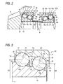
- Fig. 2 is an enlarged cross-sectional view showing a condition in which pinion shaft-supporting double row ball bearings are used
- Fig. 3 is a an enlarged cross-sectional view showing the double row ball bearing alone.
- the differential apparatus 1 includes a differential case 2.
- This differential case 2 comprises a front case 3 and a rear case 4, and the two cases 3 and 4 are connected together by a bolt/nut arrangement 2a.
- Bearing-mounting annular walls 27A and 27B are formed within the front case 3.
- the differential case 2 contains a differential speed-change mechanism 5 connecting right and left wheels together in a differential manner, and a pinion shaft (drive pinion) 7 having a pinion gear 6 formed at one end thereof.
- the pinion gear 6 is in mesh with a ring gear 8 of the differential speed-change mechanism 5.
- a shaft portion 9 of the pinion shaft 7 is stepped to decrease in diameter sequentially toward the other end thereof.
- the one end portion (pinion gear-side portion) of the shaft portion 9 of the pinion shaft 7 is supported on the annular wall 27A via the first double row angular contact ball bearing (hereinafter referred to merely as “double row ball bearing") 10 so as to rotate about an axis of the pinion shaft.
- the other end portion (anti-pinion-gear-side portion) of the shaft portion 9 is supported on the annular wall 27B via the second double row angular contact ball bearing (hereinafter referred to merely as "double row ball bearing"). 25 so as to rotate about the axis of the pinion shaft.
- the first double row ball bearing 10 comprises a single first outer ring member 11 having a pinion gear-side larger-diameter outer ring raceway surface 11a and an anti-pinion-gear-side smaller-diameter outer ring raceway surface 11b, and a first assembly 21.
- the first double row ball bearing 10 is assembled by mounting the first assembly 21 onto the first outer ring member 11 in the direction of the axis of the pinion shaft and also in a direction away from the pinion gear.
- the first outer ring member 11 is fitted on an inner peripheral surface of the annular wall 27A.
- a counter-bored outer ring is used as this first outer ring member 11.
- the first outer ring member 11 has a flat surface portion 11c formed between the larger-diameter outer ring raceway surface 11a and the smaller-diameter outer ring raceway surface 11b, and this flat surface portion 11c is larger in diameter than the smaller-diameter outer ring raceway surface 11b, and is continuous with the larger-diameter outer ring raceway surface 11a.
- the inner peripheral surface of the first outer ring member 11 is formed into a slanting shape.
- the first assembly 21 comprises a single first inner ring member 13 having a larger-diameter inner ring raceway surface 13a opposed to the larger-diameter outer ring raceway surface 11a of the first outer ring member 11 in the radial direction and a smaller-diameter inner ring raceway surface 13b opposed to the smaller-diameter outer ring raceway surface 11b in the radial direction, a pinion gear-side larger-diameter-side ball group 15, an anti-pinion-gear-side smaller-diameter-side ball group 1.6, a resin-made cage 19 holding balls 17 (forming the ball group 15) at equal intervals in the circumferential direction, and a resin-made cage 20 holding balls 18 (forming the ball group 16) at equal intervals in the circumferential direction.
- a counter-bored inner ring is used as the first inner ring member 13.
- the pinion shaft 7 is passed through the first inner ring member 13.
- the first inner ring member 13 has a flat surface portion 13c formed between the larger-diameter inner ring raceway surface 13a and the smaller-diameter inner ring raceway surface 13b, and this flat surface portion 13c is larger in diameter than the smaller-diameter inner ring raceway surface 13b, and is continuous with the larger-diameter inner ring raceway surface 13a.
- the outer peripheral surface of the first inner ring member 13 is formed into a stepped shape.
- first inner ring member 13 abuts against an end surface of the pinion gear 6 in the axial direction, and the first inner ring member 13 is held between the end surface of the pinion gear 6 and a preload-setting plastic spacer 23 (fitted on an intermediate portion of the shaft portion 9 of the pinion gear 7) in the axial direction.
- each ball 17 of the larger-diameter-side ball group 15 is equal in diameter to each ball 18 of the smaller-diameter-side ball group 16, and the ball groups 15 and 16 have different pitch circle diameters D1 and D2, respectively, as shown in Fig. 3. Namely, the pitch circle diameter D1 of the larger-diameter-side ball group 15 is larger than the pitch circle diameter D2 of the smaller-diameter-side ball group 16.
- the first double row ball bearing 10 having the ball groups 15 and 16 having the different pitch circle diameters D1 and D2 is called "a tandem-type double row ball bearing".
- the balls 17 and 18 are made, for example, of bearing steel such as JIS SUJ2 or SAE52100, and their surface hardness is set to 62 to 66 on a Rockwell C hardness (HRC) scale.
- HRC Rockwell C hardness
- the first outer ring member 11 and the first inner ring member 13 are made of carburized steel (such for example as JIS SCr420, SAE5120 or the like) containing 0.1 to 1.0 wt.% C (carbon).
- the first outer ring member 11 and the first inner ring member 13 are applied to a heat treatment such as a carbonitriding treatment or a high concentration carburizing treatment, and as a result the surface hardness of each of the first outer ring member 11 and the first inner ring member 13 in a region from its surface to a depth of 50 ⁇ m is set to HRC 63 to 67 which is substantially equal to the surface hardness of the balls 17 and 18.
- the amount of surface retained austenite is not smaller than 20% and not larger than 25%.
- the first outer ring member 11 and the first inner ring member 13 are produced by the following method.
- a carburizing and quenching treatment is applied to a bearing part stock (made of carburized steel) beforehand worked into a predetermined shape, and then a sub-zero treatment is applied to the bearing part after it is applied to a preliminary tempering treatment, and further a complete tempering treatment is applied to the bearing part.
- the carburizing and quenching treatment is carried by holding the bearing part at a temperature of 900 to 950°C for a predetermined period of time. At this time, the surface hardness of the carburized and quenched surface or layer is HRC55 to 65, and the amount of retained austenite is about 30 to about 65%.
- the preliminary tempering treatment is carried out by holding the bearing part at a temperature of 110 to 130°C for one hour or more.
- the sub-zero treatment is carried out by holding the bearing part at a temperature of -50 to -80°C for one hour or more.
- the surface hardness after the sub-zero treatment is HRC63 to 68, and the amount of the retained austenite is about 20 to about 25%.
- a secondary quenching (hardening) treatment is carried out, and further after a similar preliminary tempering treatment and a similar sub-zero treatment as described above are carried out, a complete tempering treatment is carried out.
- This secondary quenching treatment is carried out by heat-treating the bearing part at a temperature of 800 to 850°C for 0.5 hour or more and then by cooling it, for example, by oil.
- the complete tempering treatment is carried out by holding the bearing part at a temperature of 140 to 175°C for two hours or more.
- the desired retained austenite amount can be obtained. Namely, when the sub-zero treatment is carried out without effecting the preliminary tempering treatment, the austenite is liable to be decomposed to become martensite, so that the retained austenite amount is reduced. However, by effecting the preliminary tempering treatment, the retained austenite which is unstable after the carburizing and quenching treatment becomes stable, and is less liable to become martensite even when the sub-zero treatment is carried out. Incidentally, in the above method, the need for the preliminary tempering treatment can, in some cases, be obviated by suitably adjusting the treatment temperature of the sub-zero treatment.
- first outer and inner ring members corresponding respectively to the first outer and inner ring members 11 and 13
- HRC60 the surface hardness of first outer and inner ring members
- the larger-diameter inner ring raceway surface 13a and the smaller-diameter inner ring raceway surface 13b have substantially the same radius of curvature as shown in Fig. 3, and this radius of curvature is represented by Ri.
- the larger-diameter outer ring raceway surface 11a and the smaller-diameter outer ring raceway surface 11b have substantially the same radius of curvature, and this radius of curvature is represented by Ro.
- the diameter of the balls 17 and 18 is represented by Bd.
- the radius Ri of curvature, the radius Ro of curvature and the diameter Bd are so determined as to satisfy the following formulas (1), (2) and (3).
- ⁇ 1, ⁇ 2 is set to any of 20°, 25°, 30°, 35°, 40° and 45°.
- the second double row ball bearing 25 comprises a single second outer ring member 12 having a pinion gear-side smaller-diameter outer ring raceway surface 12a and an anti-pinion-gear-side larger-diameter outer ring raceway surface 12b, and a second assembly 22.
- the second double row ball bearing 25 is assembled by mounting the second assembly 22 onto the second outer ring member 12 in the direction of the axis of the pinion shaft and also in the direction toward the pinion gear.
- the second outer ring member 12 has a flat surface portion 12c formed between the smaller-diameter outer ring raceway surface 12a and the larger-diameter outer ring raceway surface 12b, and this flat surface portion 12c is larger in diameter than the smaller-diameter outer ring raceway surface 12a, and is continuous with the larger-diameter outer ring raceway surface 12b.
- the inner peripheral surface of the second outer ring member 12 is formed into a slanting shape.
- the second outer ring member 12 is fitted on an inner peripheral surface of the annular wall 27B.
- a counter-bored outer ring is used as this second outer ring member 12.
- the second assembly 22 comprises a single second inner ring member 14 having a smaller-diameter inner ring raceway surface 14a opposed to the smaller-diameter outer ring raceway surface 12a of the second outer ring member 12 in the radial direction and a larger-diameter inner ring raceway surface 14b opposed to the larger-diameter outer ring raceway surface 12b in the radial direction, a pinion gear-side smaller-diameter-side ball group 28, an anti-pinion-gear-side larger-diameter-side ball group 29, a cage 32 holding balls 30 (forming the ball group 28) at equal intervals in the circumferential direction, and a cage 33 holding balls 31 (forming the ball group 29) at equal intervals in the circumferential direction.
- a counter-bored inner ring is used as the second inner ring member 14.
- the pinion shaft 7 is passed through the second inner ring member 14, and the second inner ring member 14 is held between the preload-setting plastic spacer 23 and a closure plate 37 in the axial direction.
- the second inner ring member 14 has a flat surface portion 14c formed between the smaller-diameter inner ring raceway surface 14a and the larger-diameter inner ring raceway surface 14b, and this flat surface portion 14c is smaller in diameter than the larger-diameter inner ring raceway surface 14b, and is continuous with the smaller-diameter inner ring raceway surface 14a.
- the outer peripheral surface of the second inner ring member 14 is formed into a stepped shape.
- each ball 30 of the smaller-diameter-side ball group 28 is equal in diameter to each ball 31 of the larger-diameter-side ball group 29, and the ball groups 28 and 29 have different pitch circle diameters (not designated by reference numerals), respectively. Namely, the pitch circle diameter of the smaller-diameter-side ball group 28 is smaller than the pitch circle diameter of the larger-diameter-side ball group 29.
- This second double row ball bearing 25 is also a tandem-type double row ball bearing".
- the second double row ball bearing 25 is smaller in diameter than the first double row ball bearing 10. More specifically, the second outer ring member 12 is smaller in diameter than the first outer ring member 11, and the second inner ring member 14 is smaller in diameter than the first inner ring member 13, and the pitch circle diameter of the ball group 29 of the second double row ball bearing 25 is smaller than the pitch circle diameter D1 of the ball group 15 of the first double row ball bearing 10, and the pitch circle diameter of the ball group 28 of the second double row ball bearing 25 is smaller than the pitch circle diameter D2 of the ball group 16 of the first double row ball bearing 10.
- the balls 17 and 31 of the larger-diameter-side ball groups 15 and 29 are equal in diameter to the balls 18 and 30 of the smaller-diameter-side ball groups 16 and 28.
- the materials respectively forming the constituent elements (the outer ring member, the inner ring member, the balls and the cages) of the first double row ball bearing 10 are similar respectively to those of the second double row ball bearing 25, and the contact angles in the first and second double row ball bearings 10 and 25 are equal to each other although the directions of these contact angles are reversed relative to each other. Therefore, explanation of these will be omitted.
- the front case 3 has an oil circulating passageway 40 formed between its outer wall and the annular wall 27A as shown in Fig. 1, and an oil inlet 41 of the oil circulating passageway 40 is open toward the ring gear 8, and an oil outlet 42 of the oil circulating passageway 40 is open to a region between the annular walls 27A and 27B.
- the differential apparatus 1 includes a companion flange 43.
- This companion flange 43 includes a barrel portion 44, and a flange portion 45 formed integrally with the barrel portion 44.
- the barrel portion 44 is fitted on the other end portion (disposed close to a drive shaft (not shown)) of the shaft portion 9 of the pinion gear 7.
- the closure plate 37 is interposed between one end surface of the barrel portion 44 and an end surface of the second inner ring member 14 of the second double row ball bearing 25.
- An oil seal 46 is disposed between the outer peripheral surface of the barrel portion 44 and an inner peripheral surface of an opening portion (remote from the pinion gear) of the front case 3.
- a seal protection cup 47 is attached to the opening portion of the front case 3, and covers the oil seal 46.
- a threaded portion 48 is formed at the other end portion of the shaft portion 9, and projects into a recess 43a formed in a central portion of the flange portion 45.
- a nut 49 is threaded on the threaded portion 48.
- the nut 49 is thus threaded on the threaded portion 48, and by doing so, the first inner ring 13 of the first double row ball bearing 10 and the second inner ring 14 of the second double row ball bearing 25 are held between the end surface of the pinion gear 6 and the end surface of the companion flange 43 in the axial direction, so that a predetermined preload is imparted to the balls 17 and 18 of the first double row ball bearing 10 and the balls 30 and 31 of the second double row ball bearing 25 through the closure plate 37 and the plastic spacer 23.
- oil 50 is stored at a predetermined level within the differential case 2 when the operation is stopped.
- the oil 50 is circulated within the differential case 2, that is, the oil 50 is spattered in accordance with the rotation of the ring gear 8, and is fed through the oil circulating passageway 40 within the front case 3, and is supplied to upper portions of the first and second double row ball bearings 10 and 25 to lubricate the first and second double row ball bearings 10 and 25.
- the first double row ball bearing 10 having a small frictional resistance is used as the pinion gear-side ball bearing (disposed close to the pinion gear 6) on which larger loads act as compared with the anti-pinion-gear side ball bearing disposed remote from the pinion gear 6.
- a rotation torque becomes smaller as compared with the tapered roller bearings used in the conventional bearing device, and the efficiency of the differential apparatus 1 can be enhanced.
- not a single row ball bearing but the double row ball bearing is used as each of the first and second ball bearings, and with this construction a larger load capacity can be achieved as compared with such a single row ball bearing, and a sufficient supporting rigidity can be obtained.
- the first double row ball bearing 10 of the tandem type in which the pitch circle diameter D1 of the pinion gear (6)-side larger-diameter-side ball group 15 is larger than the pitch circle diameter D2 of the anti-pinion-gear-side smaller-diameter-side ball group 16. Therefore, the number of the balls 17 of the pinion gear (6)-side larger-diameter-side ball group 15 (on which a larger load acts when the balls 17 and 18 of the two rows have the same diameter) can be increased, and therefore the first double row ball bearing 10 can withstand a large load.
- metallic wear powder develops within the differential case 2.
- This metallic wear powder is included in the oil 50, and intrudes into the interior of the first double row ball bearing 10, and reaches the inner and outer ring raceway surfaces thereof.
- the radius Ri of curvature of the inner ring raceway surfaces 13a and 13b and the radius Ro of curvature of the outer ring raceway surfaces 11a and 11b are both made smaller than those of conventional bearing devices, and with this construction the area of contact (receiving surface) between each ball 17 and each of the inner and outer ring raceway surfaces 13a and 11a, as well as the area of contact between each ball 18 and each of the inner and outer ring raceway surfaces 13b and 11b, increases, and a contact pressure is reduced, so that an indentation or impression is hardly formed on the inner and outer ring raceway surfaces.
- the value of the contact angle ⁇ 1, ⁇ 2 is larger than the value (20° ⁇ ( ⁇ 1, ⁇ 2) ⁇ 25°) of conventional bearing devices, and with this arrangement the load capacity for the axial load is increased.
- the surface hardness of the conventional first outer ring member (corresponding to the first outer ring member 11) is set to HRC60 to 64, whereas the surface hardness of each of the first outer ring member 11 and the first inner ring member 13 is set to HRC62 to 67, and the amount of the surface retained austenite is set to the range from not smaller than 20% to less than 25%. Therefore, in accordance with the rolling movement of the balls 17 and 18 on the respective raceway surfaces, a height h of a bulged portion of the indentation becomes small with time (in a short time).
- Fig. 5 is a graph in which the horizontal axis represents surface hardness (HRC), and the vertical axis represents a height h ( ⁇ m) of a bulged portion 60 of an indentation.
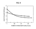
- Fig. 6 is a graph showing results obtained through tests, in which the horizontal axis represents a number of stress repetitions (cycles), and the vertical axis represents a height h ( ⁇ m) of a bulged portion 60 of an indentation.
- HRC surface hardness
- Fig. 6 is a graph showing results obtained through tests, in which the horizontal axis represents a number of stress repetitions (cycles), and the vertical axis represents a height h ( ⁇ m) of a bulged portion 60 of an indentation.
- marks O represent data obtained when a test piece having a surface hardness of HRC62.2 and a surface retained austenite amount of 16.9% was used
- marks ⁇ represent data obtained when a test piece having a surface hardness of HRC62.9 and a surface retained austenite amount of 31.5% was used.
- the bearings 10 and 25 are not limited to such use.
- the bearing device of the invention can be applied to the type of apparatus in which one bearing ring (one constituent part of a double row ball bearing) is mounted on one of a shaft and a housing, while the other constituent part is mounted on the other of the shaft and the housing, and the shaft is passed through the housing.
Landscapes
- Engineering & Computer Science (AREA)
- Chemical & Material Sciences (AREA)
- Mechanical Engineering (AREA)
- General Engineering & Computer Science (AREA)
- Organic Chemistry (AREA)
- Metallurgy (AREA)
- Materials Engineering (AREA)
- Chemical Kinetics & Catalysis (AREA)
- Physics & Mathematics (AREA)
- Thermal Sciences (AREA)
- Crystallography & Structural Chemistry (AREA)
- Rolling Contact Bearings (AREA)
- General Details Of Gearings (AREA)
Abstract
Description
- This invention relates to a ball bearing for supporting, for example, a pinion shaft used in a differential apparatus mounted on a vehicle or the like.
- Generally, a differential apparatus mounted on a vehicle has a pinion shaft mounted in a case, and a head-side portion and a tail-side portion of the pinion shaft are rotatably supported by a bearing device (see, for example,
JP-A-11-48805 - As shown in Fig. 7,
tapered roller bearings pinion shaft 71 in the abovedifferential apparatus 70. - In the above conventional bearing device, the
tapered roller bearings pinion shaft 71. Therefore, a torque during the rotation of thepinion shaft 71 becomes large. - Therefore, it may be proposed to use ball bearings instead of the
tapered roller bearings - According to the present invention, there is provided a ball bearing for a pinion shaft including:
- an inner ring member for fitting on an outer peripheral surface of the pinion shaft;
- an outer ring member disposed in concentric relation to said inner ring member; and
- a plurality of balls disposed between an inner ring raceway surface formed on an outer peripheral surface of said inner ring member and an outer ring raceway surface formed on an inner peripheral surface of said outer ring member;
- wherein said inner and outer ring members and said balls are made of high-carbon chromium bearing steel or carburized. (carburizing) bearing steel; and
- at least said inner ring member out of said inner and outer ring members is applied to a carbonitriding treatment and a hardening heat treatment, thereby forming a rolling surface layer on said inner ring member, so that hardness of said inner ring raceway surface is substantially the same as surface hardness of said balls.
- In the above construction, the hardness of the raceway surface of at least the inner ring member out of the inner and outer ring members, that is, the hardness of the inner ring raceway surface, is substantially the same as the surface hardness of the balls, and therefore a load-withstanding performance is enhanced, and a lifetime of the bearing is prolonged.
- Furthermore, in the above ball bearing for the pinion shaft, the surface of the balls is set to a Rockwell C hardness value of 63 to 67, and the surface of the inner ring member is set to a Rockwell C hardness value of 62 to 67, and the amount of surface retained austenite in the inner ring member is set to 20% to 45%.
- Therefore, an indentation due to metallic powder is hardly formed on the raceway surface, and even if such indentation is formed, a height of a bulged portion of the indentation becomes small with time, that is, in a short time, in accordance with the rolling movement of the balls on the raceway surface.
- Examples of the high-carbon chromium bearing steel used in the present invention include JIS specification SUJ2 steel, SUJ3 steel and SAE52100 steel. Examples of carburized (carburizing) steel used in the invention include JIS specification SCr420 material, SCr435 material, SCM430 material, SCM435 material, SCr430 material, SAE5120 material, SAE5130 material and SAE8620 material.
- As is clear from the foregoing description, in the present invention, the load-withstanding performance of the bearing is enhanced, so that the lifetime of the bearing can be prolonged.
-
- Fig. 1 is a cross-sectional view roughly showing the construction of a differential apparatus incorporating a preferred embodiment of a bearing device of the present invention.
- Fig. 2 is an enlarged cross-sectional view showing a condition in which pinion shaft-supporting double row ball bearings are used.
- Fig. 3 is a an enlarged cross-sectional view showing the double row ball bearing alone.
- Fig. 4 is an enlarged view showing an indentation formed on a raceway surface.
- Fig. 5 is a graph in which the horizontal axis represents surface hardness (HRC), and the vertical axis represents a height of a bulged portion of an indentation.
- Fig. 6 is a graph in which the horizontal axis represents a number of stress repetitions, and the vertical axis represents a height of a bulged portion of an indentation.
- Fig. 7 is a cross-sectional view roughly showing the construction of a conventional differential apparatus.
- A preferred embodiment of a pinion shaft-supporting ball bearing of the present invention (that is, a ball bearing for supporting a pinion shaft of a differential apparatus) will now be described with reference to the drawings.
- Fig. 1 is a cross-sectional view roughly showing the construction of the differential apparatus, Fig. 2 is an enlarged cross-sectional view showing a condition in which pinion shaft-supporting double row ball bearings are used, and Fig. 3 is a an enlarged cross-sectional view showing the double row ball bearing alone.
- First, the overall construction of the
differential apparatus 1 will be described. As shown in Fig. 1, thedifferential apparatus 1 includes adifferential case 2. Thisdifferential case 2 comprises afront case 3 and a rear case 4, and the twocases 3 and 4 are connected together by a bolt/nut arrangement 2a. Bearing-mountingannular walls front case 3. - The
differential case 2 contains a differential speed-change mechanism 5 connecting right and left wheels together in a differential manner, and a pinion shaft (drive pinion) 7 having apinion gear 6 formed at one end thereof. Thepinion gear 6 is in mesh with aring gear 8 of the differential speed-change mechanism 5. Ashaft portion 9 of the pinion shaft 7 is stepped to decrease in diameter sequentially toward the other end thereof. - The one end portion (pinion gear-side portion) of the
shaft portion 9 of the pinion shaft 7 is supported on theannular wall 27A via the first double row angular contact ball bearing (hereinafter referred to merely as "double row ball bearing") 10 so as to rotate about an axis of the pinion shaft. Also, the other end portion (anti-pinion-gear-side portion) of theshaft portion 9 is supported on theannular wall 27B via the second double row angular contact ball bearing (hereinafter referred to merely as "double row ball bearing"). 25 so as to rotate about the axis of the pinion shaft. - As shown in Fig. 2, the first double row ball bearing 10 comprises a single first
outer ring member 11 having a pinion gear-side larger-diameter outerring raceway surface 11a and an anti-pinion-gear-side smaller-diameter outerring raceway surface 11b, and afirst assembly 21. The first double row ball bearing 10 is assembled by mounting thefirst assembly 21 onto the firstouter ring member 11 in the direction of the axis of the pinion shaft and also in a direction away from the pinion gear. - The first
outer ring member 11 is fitted on an inner peripheral surface of theannular wall 27A. A counter-bored outer ring is used as this firstouter ring member 11. The firstouter ring member 11 has aflat surface portion 11c formed between the larger-diameter outerring raceway surface 11a and the smaller-diameter outerring raceway surface 11b, and thisflat surface portion 11c is larger in diameter than the smaller-diameter outerring raceway surface 11b, and is continuous with the larger-diameter outerring raceway surface 11a. With this construction, the inner peripheral surface of the firstouter ring member 11 is formed into a slanting shape. - The
first assembly 21 comprises a single firstinner ring member 13 having a larger-diameter innerring raceway surface 13a opposed to the larger-diameter outerring raceway surface 11a of the firstouter ring member 11 in the radial direction and a smaller-diameter innerring raceway surface 13b opposed to the smaller-diameter outerring raceway surface 11b in the radial direction, a pinion gear-side larger-diameter-side ball group 15, an anti-pinion-gear-side smaller-diameter-side ball group 1.6, a resin-madecage 19 holding balls 17 (forming the ball group 15) at equal intervals in the circumferential direction, and a resin-madecage 20 holding balls 18 (forming the ball group 16) at equal intervals in the circumferential direction. A counter-bored inner ring is used as the firstinner ring member 13. The pinion shaft 7 is passed through the firstinner ring member 13. - The first
inner ring member 13 has aflat surface portion 13c formed between the larger-diameter innerring raceway surface 13a and the smaller-diameter innerring raceway surface 13b, and thisflat surface portion 13c is larger in diameter than the smaller-diameter innerring raceway surface 13b, and is continuous with the larger-diameter innerring raceway surface 13a. With this construction, the outer peripheral surface of the firstinner ring member 13 is formed into a stepped shape. - An end surface of the first
inner ring member 13 abuts against an end surface of thepinion gear 6 in the axial direction, and the firstinner ring member 13 is held between the end surface of thepinion gear 6 and a preload-setting plastic spacer 23 (fitted on an intermediate portion of theshaft portion 9 of the pinion gear 7) in the axial direction. - In the first double row ball bearing 10, each
ball 17 of the larger-diameter-side ball group 15 is equal in diameter to eachball 18 of the smaller-diameter-side ball group 16, and theball groups side ball group 15 is larger than the pitch circle diameter D2 of the smaller-diameter-side ball group 16. The first double row ball bearing 10 having theball groups - The
balls - The first
outer ring member 11 and the firstinner ring member 13 are made of carburized steel (such for example as JIS SCr420, SAE5120 or the like) containing 0.1 to 1.0 wt.% C (carbon). The firstouter ring member 11 and the firstinner ring member 13 are applied to a heat treatment such as a carbonitriding treatment or a high concentration carburizing treatment, and as a result the surface hardness of each of the firstouter ring member 11 and the firstinner ring member 13 in a region from its surface to a depth of 50 µm is set to HRC 63 to 67 which is substantially equal to the surface hardness of theballs - The first
outer ring member 11 and the firstinner ring member 13 are produced by the following method. A carburizing and quenching treatment is applied to a bearing part stock (made of carburized steel) beforehand worked into a predetermined shape, and then a sub-zero treatment is applied to the bearing part after it is applied to a preliminary tempering treatment, and further a complete tempering treatment is applied to the bearing part. - The carburizing and quenching treatment is carried by holding the bearing part at a temperature of 900 to 950°C for a predetermined period of time. At this time, the surface hardness of the carburized and quenched surface or layer is HRC55 to 65, and the amount of retained austenite is about 30 to about 65%. The preliminary tempering treatment is carried out by holding the bearing part at a temperature of 110 to 130°C for one hour or more. The sub-zero treatment is carried out by holding the bearing part at a temperature of -50 to -80°C for one hour or more. The surface hardness after the sub-zero treatment is HRC63 to 68, and the amount of the retained austenite is about 20 to about 25%.
- Then, after a similar carburizing and quenching treatment as described above is carried out, a secondary quenching (hardening) treatment is carried out, and further after a similar preliminary tempering treatment and a similar sub-zero treatment as described above are carried out, a complete tempering treatment is carried out. This secondary quenching treatment is carried out by heat-treating the bearing part at a temperature of 800 to 850°C for 0.5 hour or more and then by cooling it, for example, by oil. The complete tempering treatment is carried out by holding the bearing part at a temperature of 140 to 175°C for two hours or more.
- With this method, the desired retained austenite amount can be obtained. Namely, when the sub-zero treatment is carried out without effecting the preliminary tempering treatment, the austenite is liable to be decomposed to become martensite, so that the retained austenite amount is reduced. However, by effecting the preliminary tempering treatment, the retained austenite which is unstable after the carburizing and quenching treatment becomes stable, and is less liable to become martensite even when the sub-zero treatment is carried out. Incidentally, in the above method, the need for the preliminary tempering treatment can, in some cases, be obviated by suitably adjusting the treatment temperature of the sub-zero treatment.
- In conventional rolling bearings of this type, the surface hardness of first outer and inner ring members (corresponding respectively to the first outer and
inner ring members 11 and 13) has heretofore been set to HRC60 to 64. - In the first double
row ball bearing 10 of this embodiment, the larger-diameter innerring raceway surface 13a and the smaller-diameter innerring raceway surface 13b have substantially the same radius of curvature as shown in Fig. 3, and this radius of curvature is represented by Ri. In the first doublerow ball bearing 10, the larger-diameter outerring raceway surface 11a and the smaller-diameter outerring raceway surface 11b have substantially the same radius of curvature, and this radius of curvature is represented by Ro. The diameter of theballs 


- The radius Ro of curvature is 1% larger than the radius Ri of curvature. More specifically, in the case of Ri = 0.505 ·Bd, Ro = 0.515Bd is provided.
- Incidentally, conventional rolling bearings of this type have heretofore been arranged such that the formula, 0.515·Bd ≤ Ri ≤ 0.525·Bd, and the formula, 0.525·Bd ≤ Ro ≤ 0.535·Bd, are established.
- In this embodiment, when an angle formed by an action line A1 (interconnecting two points at which the
ball 17 contacts the inner and outer ring raceway surfaces 13a and 11a) and a radial plane, that is, a contact angle, is represented by θ1, and an angle formed by an action line A2 (interconnecting two points at which theball 18 contacts the inner and outer ring raceway surfaces 13b and 11b) and a radial plane, that is, a contact angle, is represented by θ2, the relation, θ1 = θ2, is established. θ1, θ2 satisfies the following formula (4).
- More specifically, θ1, θ2 is set to any of 20°, 25°, 30°, 35°, 40° and 45°.
- As shown in Fig. 2, the second double
row ball bearing 25 comprises a single secondouter ring member 12 having a pinion gear-side smaller-diameter outerring raceway surface 12a and an anti-pinion-gear-side larger-diameter outerring raceway surface 12b, and a second assembly 22. The second doublerow ball bearing 25 is assembled by mounting the second assembly 22 onto the secondouter ring member 12 in the direction of the axis of the pinion shaft and also in the direction toward the pinion gear. The secondouter ring member 12 has aflat surface portion 12c formed between the smaller-diameter outerring raceway surface 12a and the larger-diameter outerring raceway surface 12b, and thisflat surface portion 12c is larger in diameter than the smaller-diameter outerring raceway surface 12a, and is continuous with the larger-diameter outerring raceway surface 12b. - With this construction, the inner peripheral surface of the second
outer ring member 12 is formed into a slanting shape. The secondouter ring member 12 is fitted on an inner peripheral surface of theannular wall 27B. A counter-bored outer ring is used as this secondouter ring member 12. - The second assembly 22 comprises a single second
inner ring member 14 having a smaller-diameter innerring raceway surface 14a opposed to the smaller-diameter outerring raceway surface 12a of the secondouter ring member 12 in the radial direction and a larger-diameter innerring raceway surface 14b opposed to the larger-diameter outerring raceway surface 12b in the radial direction, a pinion gear-side smaller-diameter-side ball group 28, an anti-pinion-gear-side larger-diameter-side ball group 29, acage 32 holding balls 30 (forming the ball group 28) at equal intervals in the circumferential direction, and acage 33 holding balls 31 (forming the ball group 29) at equal intervals in the circumferential direction. A counter-bored inner ring is used as the secondinner ring member 14. The pinion shaft 7 is passed through the secondinner ring member 14, and the secondinner ring member 14 is held between the preload-settingplastic spacer 23 and aclosure plate 37 in the axial direction. - The second
inner ring member 14 has aflat surface portion 14c formed between the smaller-diameter innerring raceway surface 14a and the larger-diameter innerring raceway surface 14b, and thisflat surface portion 14c is smaller in diameter than the larger-diameter innerring raceway surface 14b, and is continuous with the smaller-diameter innerring raceway surface 14a. With this construction, the outer peripheral surface of the secondinner ring member 14 is formed into a stepped shape. - In the second double
row ball bearing 25, eachball 30 of the smaller-diameter-side ball group 28 is equal in diameter to eachball 31 of the larger-diameter-side ball group 29, and theball groups side ball group 28 is smaller than the pitch circle diameter of the larger-diameter-side ball group 29. This second doublerow ball bearing 25 is also a tandem-type double row ball bearing". - The second double
row ball bearing 25 is smaller in diameter than the first doublerow ball bearing 10. More specifically, the secondouter ring member 12 is smaller in diameter than the firstouter ring member 11, and the secondinner ring member 14 is smaller in diameter than the firstinner ring member 13, and the pitch circle diameter of theball group 29 of the second doublerow ball bearing 25 is smaller than the pitch circle diameter D1 of theball group 15 of the first doublerow ball bearing 10, and the pitch circle diameter of theball group 28 of the second doublerow ball bearing 25 is smaller than the pitch circle diameter D2 of theball group 16 of the first doublerow ball bearing 10. - In the first and second double
row ball bearings balls side ball groups balls side ball groups row ball bearing 10 are similar respectively to those of the second doublerow ball bearing 25, and the contact angles in the first and second doublerow ball bearings - In the
differential apparatus 1 of this embodiment, thefront case 3 has anoil circulating passageway 40 formed between its outer wall and theannular wall 27A as shown in Fig. 1, and anoil inlet 41 of theoil circulating passageway 40 is open toward thering gear 8, and anoil outlet 42 of theoil circulating passageway 40 is open to a region between theannular walls - The
differential apparatus 1 includes acompanion flange 43. This companion flange 43 includes abarrel portion 44, and aflange portion 45 formed integrally with thebarrel portion 44. Thebarrel portion 44 is fitted on the other end portion (disposed close to a drive shaft (not shown)) of theshaft portion 9 of the pinion gear 7. - The
closure plate 37 is interposed between one end surface of thebarrel portion 44 and an end surface of the secondinner ring member 14 of the second doublerow ball bearing 25. Anoil seal 46 is disposed between the outer peripheral surface of thebarrel portion 44 and an inner peripheral surface of an opening portion (remote from the pinion gear) of thefront case 3. A seal protection cup 47 is attached to the opening portion of thefront case 3, and covers theoil seal 46. A threadedportion 48 is formed at the other end portion of theshaft portion 9, and projects into arecess 43a formed in a central portion of theflange portion 45. Anut 49 is threaded on the threadedportion 48. - The
nut 49 is thus threaded on the threadedportion 48, and by doing so, the firstinner ring 13 of the first doublerow ball bearing 10 and the secondinner ring 14 of the second doublerow ball bearing 25 are held between the end surface of thepinion gear 6 and the end surface of thecompanion flange 43 in the axial direction, so that a predetermined preload is imparted to theballs row ball bearing 10 and theballs row ball bearing 25 through theclosure plate 37 and theplastic spacer 23. - In the
differential apparatus 1 of the above construction,oil 50 is stored at a predetermined level within thedifferential case 2 when the operation is stopped. During the operation, theoil 50 is circulated within thedifferential case 2, that is, theoil 50 is spattered in accordance with the rotation of thering gear 8, and is fed through theoil circulating passageway 40 within thefront case 3, and is supplied to upper portions of the first and second doublerow ball bearings row ball bearings - In this embodiment, the first double
row ball bearing 10 having a small frictional resistance is used as the pinion gear-side ball bearing (disposed close to the pinion gear 6) on which larger loads act as compared with the anti-pinion-gear side ball bearing disposed remote from thepinion gear 6. With this arrangement, a rotation torque becomes smaller as compared with the tapered roller bearings used in the conventional bearing device, and the efficiency of thedifferential apparatus 1 can be enhanced. And besides, not a single row ball bearing but the double row ball bearing is used as each of the first and second ball bearings, and with this construction a larger load capacity can be achieved as compared with such a single row ball bearing, and a sufficient supporting rigidity can be obtained. - Furthermore, there is used the first double
row ball bearing 10 of the tandem type in which the pitch circle diameter D1 of the pinion gear (6)-side larger-diameter-side ball group 15 is larger than the pitch circle diameter D2 of the anti-pinion-gear-side smaller-diameter-side ball group 16. Therefore, the number of theballs 17 of the pinion gear (6)-side larger-diameter-side ball group 15 (on which a larger load acts when theballs row ball bearing 10 can withstand a large load. - Incidentally, in the above
differential apparatus 1, metallic wear powder develops within thedifferential case 2. This metallic wear powder is included in theoil 50, and intrudes into the interior of the first doublerow ball bearing 10, and reaches the inner and outer ring raceway surfaces thereof. - However, as indicated by the formulas (2) and (3), the radius Ri of curvature of the inner ring raceway surfaces 13a and 13b and the radius Ro of curvature of the outer ring raceway surfaces 11a and 11b are both made smaller than those of conventional bearing devices, and with this construction the area of contact (receiving surface) between each
ball 17 and each of the inner and outer ring raceway surfaces 13a and 11a, as well as the area of contact between eachball 18 and each of the inner and outer ring raceway surfaces 13b and 11b, increases, and a contact pressure is reduced, so that an indentation or impression is hardly formed on the inner and outer ring raceway surfaces. And besides, as indicated in the above formula (4), the value of the contact angle θ1, θ2 is larger than the value (20° ≤ (θ1, θ2) ≤ 25°) of conventional bearing devices, and with this arrangement the load capacity for the axial load is increased. - As described above, in this embodiment, although an indentation or impression is hardly formed on the inner and outer ring raceway surfaces, there are occasions when such indentation is formed as shown in an enlarged view of Fig. 4. However, the surface hardness of the conventional first outer ring member (corresponding to the first outer ring member 11) is set to HRC60 to 64, whereas the surface hardness of each of the first
outer ring member 11 and the firstinner ring member 13 is set to HRC62 to 67, and the amount of the surface retained austenite is set to the range from not smaller than 20% to less than 25%. Therefore, in accordance with the rolling movement of theballs - Fig. 5 is a graph in which the horizontal axis represents surface hardness (HRC), and the vertical axis represents a height h (µm) of a bulged
portion 60 of an indentation. Fig. 6 is a graph showing results obtained through tests, in which the horizontal axis represents a number of stress repetitions (cycles), and the vertical axis represents a height h (µm) of a bulgedportion 60 of an indentation. - In Fig. 6, marks O represent data obtained when a test piece having a surface hardness of HRC62.2 and a surface retained austenite amount of 16.9% was used, and marks □ represent data obtained when a test piece having a surface hardness of HRC62.9 and a surface retained austenite amount of 31.5% was used.
- It will be appreciated from Fig. 6 that when the retained austenite amount increases, the height of the bulged portion will not become smaller than a certain level even when the number of stress repetitions increases. It is thought that the fact that the height h of the bulged
portion 60 will not become small with the increased amount of the surface retained austenite is attributable to work hardening developing in the bulgedportion 60. - Thus, in the embodiment of the invention, even when an indentation is formed on the inner and outer raceway surfaces, this indentation is decreased in a short time into such a small size as not to adversely affect the operation of the bearing. The above advantageous effects are also achieved in the second double
row ball bearing 25. - In the above embodiment, although the first double
row ball bearing 10 and the second doublerow ball bearing 25 are used as the bearings for supporting the pinion shaft of thedifferential apparatus 1 of the vehicle, thebearings
Claims (2)
- A ball bearing for a pinion shaft comprising:an inner ring member for fitting on an outer peripheral surface of the pinion shaft;an outer ring member disposed in concentric relation to said inner ring member; anda plurality of balls disposed between an inner ring raceway surface formed on an outer peripheral surface of said inner ring member and an outer ring raceway surface formed on an inner peripheral surface of said outer ring member;wherein said inner and outer ring members and said balls are made of high-carbon chromium bearing steel or carburized bearing steel; andat least said inner ring member out of said inner and outer ring members is applied to a carbonitriding treatment and a hardening heat treatment, thereby forming a rolling surface layer on said inner ring member, so that hardness of said inner ring raceway surface is substantially the same as surface hardness of said balls.
- A ball bearing for a pinion shaft according to claim 1, wherein the surface of said balls is set to a Rockwell C hardness value of 63 to 67, and the surface of said inner ring member is set to a Rockwell C hardness value of 62 to 67, and the amount of surface retained austenite in said inner ring member is set to 20% to 45%.
Applications Claiming Priority (1)
| Application Number | Priority Date | Filing Date | Title |
|---|---|---|---|
| JP2006023379A JP2007205429A (en) | 2006-01-31 | 2006-01-31 | Pinion shaft ball bearings |
Publications (2)
| Publication Number | Publication Date |
|---|---|
| EP1816230A2 true EP1816230A2 (en) | 2007-08-08 |
| EP1816230A3 EP1816230A3 (en) | 2008-09-24 |
Family
ID=37808169
Family Applications (1)
| Application Number | Title | Priority Date | Filing Date |
|---|---|---|---|
| EP07002124A Withdrawn EP1816230A3 (en) | 2006-01-31 | 2007-01-31 | Ball bearing for pinion shaft |
Country Status (3)
| Country | Link |
|---|---|
| US (1) | US20070196039A1 (en) |
| EP (1) | EP1816230A3 (en) |
| JP (1) | JP2007205429A (en) |
Families Citing this family (6)
| Publication number | Priority date | Publication date | Assignee | Title |
|---|---|---|---|---|
| US7934871B2 (en) * | 2007-03-12 | 2011-05-03 | Jtekt Corporation | Double row ball bearing |
| DE102007049982A1 (en) * | 2007-10-18 | 2009-04-23 | Knorr-Bremse Systeme für Nutzfahrzeuge GmbH | Rolling bearings, in particular for the storage of a commercial vehicle wheel |
| JP5235392B2 (en) * | 2007-12-04 | 2013-07-10 | 株式会社ジェイテクト | Double row angular contact ball bearings |
| JP2012172730A (en) * | 2011-02-18 | 2012-09-10 | Nsk Ltd | Pinion shaft rotation support device |
| JP2014029176A (en) * | 2012-07-31 | 2014-02-13 | Jtekt Corp | Revolving shaft device |
| JP7681942B2 (en) * | 2019-10-01 | 2025-05-23 | Ntn株式会社 | Bearing parts |
Family Cites Families (28)
| Publication number | Priority date | Publication date | Assignee | Title |
|---|---|---|---|---|
| US1325113A (en) * | 1919-12-16 | Ball-bearing | ||
| DE3503215A1 (en) * | 1985-01-31 | 1986-08-07 | Schaeffler Wälzlager GmbH, 6650 Homburg | Angular contact ball bearing and method for assembling such an angular contact ball bearing |
| DE3540224A1 (en) * | 1985-11-13 | 1987-05-14 | Kugelfischer G Schaefer & Co | Double row angular contact ball bearing |
| JP2962817B2 (en) * | 1990-11-28 | 1999-10-12 | 日本精工株式会社 | Rolling bearing |
| JPH05148535A (en) * | 1991-06-07 | 1993-06-15 | Kobe Steel Ltd | Production of surface hardened parts having decreased heat treating strain and excellent bending fatigue strength |
| JP3241491B2 (en) * | 1993-06-29 | 2001-12-25 | 大同特殊鋼株式会社 | Rolling bearing for high temperature and high speed rotation |
| JP3646467B2 (en) * | 1996-07-31 | 2005-05-11 | 日本精工株式会社 | Rolling bearing |
| JP3698866B2 (en) * | 1997-07-31 | 2005-09-21 | 光洋精工株式会社 | Differential device |
| JPH11100643A (en) * | 1997-09-25 | 1999-04-13 | Ntn Corp | Rolling bearing |
| JP2000065069A (en) * | 1998-08-25 | 2000-03-03 | Nippon Seiko Kk | Ball bearing |
| US6328477B1 (en) * | 1998-11-27 | 2001-12-11 | Ntn Corporation | Tapered roller bearings and gear shaft support devices |
| JP2001200314A (en) * | 2000-01-18 | 2001-07-24 | Ntn Corp | Wheel bearing device |
| JP2002060847A (en) * | 2000-08-22 | 2002-02-28 | Ntn Corp | Heat-resistant carburized rolling bearing component and method of manufacturing the same |
| EP1443228B1 (en) * | 2001-11-08 | 2011-03-30 | JTEKT Corporation | Bearing device for supporting pinion shaft |
| JP2003232346A (en) * | 2001-12-04 | 2003-08-22 | Koyo Seiko Co Ltd | Bearing device for supporting pinion shaft |
| JP4348964B2 (en) * | 2002-04-15 | 2009-10-21 | 日本精工株式会社 | Rolling bearing for belt type continuously variable transmission and method for manufacturing the same |
| DE10239742B4 (en) * | 2002-05-10 | 2011-07-28 | Schaeffler Technologies GmbH & Co. KG, 91074 | Single-sided double angular contact ball bearings |
| DE10325584A1 (en) * | 2002-06-18 | 2004-03-11 | Ntn Corp. | wheel bearing device |
| JP2004060797A (en) * | 2002-07-30 | 2004-02-26 | Koyo Seiko Co Ltd | Roller member and its manufacturing method |
| US7059777B2 (en) * | 2002-09-30 | 2006-06-13 | Koyo Seiko Co., Ltd. | Assembly for ball bearing with double raceway and method of manufacturing ball bearing with double raceway |
| JP4419388B2 (en) * | 2002-12-18 | 2010-02-24 | 株式会社ジェイテクト | Differential |
| JP4285017B2 (en) * | 2002-12-19 | 2009-06-24 | 株式会社ジェイテクト | Differential equipment |
| US7334943B2 (en) * | 2003-02-28 | 2008-02-26 | Ntn Corporation | Differential support structure, differential's component, method of manufacturing differential support structure, and method of manufacturing differential's component |
| JP4573535B2 (en) * | 2003-02-28 | 2010-11-04 | Ntn株式会社 | Differential support structure and differential components |
| JP2004301321A (en) * | 2003-03-14 | 2004-10-28 | Ntn Corp | Bearing for alternator and bearing for pulley |
| JP2004293632A (en) * | 2003-03-26 | 2004-10-21 | Ntn Corp | Rolling bearing |
| JP2005068453A (en) * | 2003-08-28 | 2005-03-17 | Nissan Motor Co Ltd | High surface pressure resistant parts and manufacturing method thereof |
| JP2006177441A (en) * | 2004-12-22 | 2006-07-06 | Jtekt Corp | Pinion shaft support device for vehicle |
-
2006
- 2006-01-31 JP JP2006023379A patent/JP2007205429A/en active Pending
-
2007
- 2007-01-30 US US11/699,432 patent/US20070196039A1/en not_active Abandoned
- 2007-01-31 EP EP07002124A patent/EP1816230A3/en not_active Withdrawn
Also Published As
| Publication number | Publication date |
|---|---|
| US20070196039A1 (en) | 2007-08-23 |
| JP2007205429A (en) | 2007-08-16 |
| EP1816230A3 (en) | 2008-09-24 |
Similar Documents
| Publication | Publication Date | Title |
|---|---|---|
| JP5375969B2 (en) | Rotation support device for pinion shaft | |
| US20070242913A1 (en) | Rolling bearing device for supporting pinion shaft | |
| US20100189386A1 (en) | Angular-contact ball bearing in a tandem arrangement, and bearing arrangement having the angular-contact ball bearing | |
| EP2003351A1 (en) | Double-row rolling bearing for supporting pinion shaft, and rolling bearing device with the same | |
| US7059777B2 (en) | Assembly for ball bearing with double raceway and method of manufacturing ball bearing with double raceway | |
| US20070196039A1 (en) | Ball bearing for pinion shaft | |
| US20140270616A1 (en) | Tapered roller bearing and mounting structure thereof | |
| AU2005208034A1 (en) | Double-row rolling bearing | |
| EP2789705B1 (en) | Machine part, rolling bearing, conical roller bearing and method for manufacturing machine part | |
| US6969201B2 (en) | Wheel bearing device | |
| US20090110340A1 (en) | Bearing apparatus for supporting pinion shaft | |
| US8794843B2 (en) | Rotation support device for pinion shaft | |
| JP2023054008A (en) | Method for manufacturing flexible meshing-type gear device | |
| EP1674744A1 (en) | Vehicle pinion shaft support system | |
| JP2000161349A (en) | Gear shaft support device for vehicle | |
| JP2007211794A (en) | Wheel bearing device | |
| JP2002323049A (en) | Rolling bearing | |
| JP2009079680A (en) | Tandem type double-row angular ball bearing and differential device | |
| JP2003120679A (en) | Pin type roller bearing | |
| JP2001116055A (en) | Double row conical roller bearing | |
| JP5105859B2 (en) | Wheel bearing device | |
| WO2024101264A1 (en) | Rolling bearing | |
| JP4936739B2 (en) | Wheel bearing device | |
| JP6725993B2 (en) | Wheel bearing device | |
| EP2684708A1 (en) | Shaft member for wheel rolling bearing device |
Legal Events
| Date | Code | Title | Description |
|---|---|---|---|
| PUAI | Public reference made under article 153(3) epc to a published international application that has entered the european phase |
Free format text: ORIGINAL CODE: 0009012 |
|
| AK | Designated contracting states |
Kind code of ref document: A2 Designated state(s): AT BE BG CH CY CZ DE DK EE ES FI FR GB GR HU IE IS IT LI LT LU LV MC NL PL PT RO SE SI SK TR |
|
| AX | Request for extension of the european patent |
Extension state: AL BA HR MK YU |
|
| PUAL | Search report despatched |
Free format text: ORIGINAL CODE: 0009013 |
|
| AK | Designated contracting states |
Kind code of ref document: A3 Designated state(s): AT BE BG CH CY CZ DE DK EE ES FI FR GB GR HU IE IS IT LI LT LU LV MC NL PL PT RO SE SI SK TR |
|
| AX | Request for extension of the european patent |
Extension state: AL BA HR MK RS |
|
| 17P | Request for examination filed |
Effective date: 20090107 |
|
| 17Q | First examination report despatched |
Effective date: 20090212 |
|
| AKX | Designation fees paid |
Designated state(s): DE FR |
|
| GRAP | Despatch of communication of intention to grant a patent |
Free format text: ORIGINAL CODE: EPIDOSNIGR1 |
|
| STAA | Information on the status of an ep patent application or granted ep patent |
Free format text: STATUS: THE APPLICATION IS DEEMED TO BE WITHDRAWN |
|
| 18D | Application deemed to be withdrawn |
Effective date: 20100715 |