EP1816066A1 - Electrical bicycle shift control device - Google Patents
Electrical bicycle shift control device Download PDFInfo
- Publication number
- EP1816066A1 EP1816066A1 EP06025482A EP06025482A EP1816066A1 EP 1816066 A1 EP1816066 A1 EP 1816066A1 EP 06025482 A EP06025482 A EP 06025482A EP 06025482 A EP06025482 A EP 06025482A EP 1816066 A1 EP1816066 A1 EP 1816066A1
- Authority
- EP
- European Patent Office
- Prior art keywords
- switch
- operating members
- switch operating
- bicycle
- control device
- Prior art date
- Legal status (The legal status is an assumption and is not a legal conclusion. Google has not performed a legal analysis and makes no representation as to the accuracy of the status listed.)
- Granted
Links
Images


Classifications
-
- B—PERFORMING OPERATIONS; TRANSPORTING
- B62—LAND VEHICLES FOR TRAVELLING OTHERWISE THAN ON RAILS
- B62M—RIDER PROPULSION OF WHEELED VEHICLES OR SLEDGES; POWERED PROPULSION OF SLEDGES OR SINGLE-TRACK CYCLES; TRANSMISSIONS SPECIALLY ADAPTED FOR SUCH VEHICLES
- B62M25/00—Actuators for gearing speed-change mechanisms specially adapted for cycles
- B62M25/08—Actuators for gearing speed-change mechanisms specially adapted for cycles with electrical or fluid transmitting systems
-
- Y—GENERAL TAGGING OF NEW TECHNOLOGICAL DEVELOPMENTS; GENERAL TAGGING OF CROSS-SECTIONAL TECHNOLOGIES SPANNING OVER SEVERAL SECTIONS OF THE IPC; TECHNICAL SUBJECTS COVERED BY FORMER USPC CROSS-REFERENCE ART COLLECTIONS [XRACs] AND DIGESTS
- Y10—TECHNICAL SUBJECTS COVERED BY FORMER USPC
- Y10T—TECHNICAL SUBJECTS COVERED BY FORMER US CLASSIFICATION
- Y10T74/00—Machine element or mechanism
- Y10T74/20—Control lever and linkage systems
- Y10T74/20396—Hand operated
- Y10T74/20402—Flexible transmitter [e.g., Bowden cable]
- Y10T74/2042—Flexible transmitter [e.g., Bowden cable] and hand operator
Definitions
- This invention generally relates to a bicycle shift control device. More specifically, the present invention relates to a bicycle shift control device that includes a switch operating member having a rider operating portion that is adjustable a relative to a base member of shift control device.
- Bicycling is becoming an increasingly more popular form of recreation as well as a means of transportation. Moreover, bicycling has become a very popular competitive sport for both amateurs and professionals. Whether the bicycle is used for recreation, transportation or competition, the bicycle industry is constantly improving the various components of the bicycle. In particular, control devices for braking and/or shifting have been extensively redesigned in recent years.
- One object of the present invention is to provide a bicycle control device having an electrical switch in which a relative mounting location of a switch operating member of the switch relative to a base member of shift control device can be adjusted.
- Another object of the present invention is to provide a bicycle control device having an electrical switch which can accommodate different rider's hand sizes and/or shifting preferences.
- a bicycle control device that basically comprises a base member, an electrical switch and a plurality of switch operating members.
- the base member is configured to be attached to a bicycle.
- the switch operating members are configured to be selectively mounted one at a time on the bicycle control device.
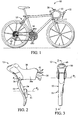
- Figure 1 is a side elevational view of bicycle equipped with a pair of bicycle control (brake/shift) devices (only one shown) coupled to a drop type handlebar in accordance with a preferred embodiment of the present invention
- Figure 2 is a side elevational view of one of the bicycle control (brake/shift) devices in accordance with the present invention
- FIG 3 is a front elevational view of the bicycle control (brake/shift) device illustrated in Figure 2 in accordance with the present invention
- FIG 4 is a rear elevational view of the bicycle control (brake/shift) device illustrated in Figures 2 and 3 in accordance with the present invention
- FIG. 5 is a cross sectional view of the bicycle control device illustrated in illustrated in Figures 2-4 in accordance with the present invention as seen along section line 5-5 of Figure 3;
- Figure 6 is an enlarged, partial rear elevational view of the brake lever and the electrical shift switch with a first one of the switch operating members mounted to the control shaft of the electrical shift switch;
- Figure 7 is an enlarged, partial cross sectional view of the brake lever with the electrical shift switch shown in elevation;
- Figure 8 is an enlarged, partial rear elevational view of the brake lever and the electrical shift switch with a second one of the switch operating members mounted to the control shaft of the electrical shift switch;
- Figure 9 is an enlarged, partial rear elevational view of the brake lever and the electrical shift switch with a third one of the switch operating members mounted to the control shaft of the electrical shift switch;
- Figure 10 is a side elevational view of a bicycle control (brake/shift) device having a pivotally mounted switch operating member in accordance with an alternate embodiment of the present invention.
- a bicycle 10 is illustrated with a pair of control devices 12 (only one shown in Figure 1) mounted in a drop type bicycle handlebar 13 in accordance with one embodiment of the present invention.
- One of the control devices 12 is operatively coupled to a rear electronic derailleur 14 and a rear braking device 15, while the control device 12 is operatively coupled to a front electronic derailleur 16 and a front braking device 17.
- the right and left hand side control devices 12 are essentially identical in construction and operation, except that they are mirror images. Thus, only one of the control devices 12 will be discussed and illustrated herein.
- a cycle computer 20 is operatively coupled between the control devices 12 and the rear and front electronic derailleurs 14 and 16.
- the cycle computer 20 can be eliminated such that the control devices 12 are directly electrically coupled to the rear and front electronic derailleurs 14 and 16.
- each of the control devices 12 includes its own built in cycle computer.
- the bicycle 10 is preferably provided with a generator such as a hub dynamo, and a battery which can be located in a portion of a frame tube such as the seat tube of the bicycle 10. The generator and the battery are electrically coupled to the control devices 12 and the rear and front electronic derailleurs 14 and 16 in a conventional manner.
- the bicycle control device 12 basically comprises a lever bracket or base member 30, a control or brake lever 32 movably coupled to the base member 30 about a pivot axis P 1 and an electrical shift switch 34 mounted on the brake lever 32.
- the base member 30 is mounted to the bicycle handlebar 13 by a conventional tube clamp 36 that is attached to the rear end of the base member 30.
- the tube clamp 36 is a conventional metal clamp and will not be discussed and/or illustrated in detail herein.
- the base member 30 is configured as a rider hand grip part or drop handlebar bracket body 30a having a first end with a handlebar mounting structure for mounting to the drop type handlebar 13 and a second end pivotally supporting the brake lever 32.
- the base member 30 has a generally rectangular transverse cross section with rounded corner such that the drop handlebar bracket body 30a includes an upper wall, a bottom wall and a pair of sidewalls.
- the tube clamp 36 is attached to the first end of the drop handlebar bracket body 30a for mounting to the drop type handlebar 13.
- the second end of the drop handlebar bracket body 30a pivotally supports the brake lever 32 by a pivot pin 38.
- the base member 30 has a pair of flanges that the brake lever 32 is located between.
- the base member 30 has an electrical unit 40 that is electrically coupled to the electrical shift switch 34 and selectively wired to the cycle computer 20 and/or one of the rear and front electronic deraille 14 and 16.
- the brake lever 32 is a cable operated brake lever that is pivotally mounted to the base member 30 for performing a bicycle braking operation.
- the brake lever 32 is attached to a brake cable 42 to operate one of the braking devices 15 and 17.
- the electrical shift switch 34 is fixedly coupled to the control lever 32 to move therewith.
- the brake lever 32 has a first end pivotally attached to the base member 30 and a second free end spaced longitudinally from the first end of the brake lever 32, with the electrical shift switch 34 mounted to the brake lever 32. More specifically, the brake lever 32 has a pair of axially aligned openings 44 that receive an end barrel or fitting of the brake cable 42. In other words, the aligned openings 44 of the control lever 32 form a cable attachment structure for the brake cable 42.
- the control lever 32 is a cable operated brake lever that is pivotally mounted to the base member 30 for performing a bicycle braking operation.
- a return spring 46 is operatively coupled between the brake lever 32 and the base member 30 to bias the brake lever 32 to a rest position.
- the return spring 46 is preferably a coil tension spring that is elongated when the brake lever 32 is moved from the rest position to a braking position.
- the brake lever 32 can be replaced with a dual action control (shifting/braking) lever that is configured and arranged as both a brake lever and a shift lever for both braking operations and gear shifting operations.
- the electrical shift switch 34 has a switch housing 48 that encloses an electrical contact arrangement 50 and a plurality of switch operating members 51, 52 and 53.
- the electrical contact arrangement 50 is provided with a pivoting portion or control shaft 50a that operates the electrical shift switch 34 in a conventional manner.
- the configuration of the electrical contact arrangement 50 can be any type of arrangement that can carry out the present invention, and thus, the electrical contact arrangement 50 will not be discussed and/ illustrated in detail herein.
- the switch operating members 51, 52 and 53 are selectively mounted one at a time to the control shaft 50a.
- the switch operating members 51, 52 and 53 that is mounted on the control shaft 50a can then pivot about a pivot axis P 2 of the control shaft 50a between a rest position and an activation position to perform a shifting operation.
- the switch operating members 51, 52 and 53 are configured to be selectively mounted one at a time on the control shaft 50a accommodate different rider's hand sizes and/or shifting preferences.
- a rider's finger F is shown in phantom lines in Figures 6, 8 and 9 to illustrate the relative positions of the rider's finger F relative to the pivot axis P 2 of the control shaft 50a.
- the switch operating member 51 is provided with a rider operating portion 51 a.
- the switch operating member 52 is provided with a rider operating portion 52a.
- the switch operating member 53 is provided with a rider operating portion 53a.
- rider operating portions 51a, 52a and 53a are configured and arranged such that when the switch operating members 51, 52 and 53 are selectively mounted to the control shaft 50a, the rider operating portions 51a, 52a and 53a will be located at different relative distances from the base member 30.
- each of the rider operating portions 51a, 52a and 53a is a rider engagement projection that is arranged to be located at a different relative location as determined relative to a longitudinal axis of the brake lever 32 when each of the switch operating members 51, 52 and 53 is selectively mounted to the control shaft 50a of the electrical switch 34.
- each of the rider operating portions 51a, 52a and 53a has a different operating location along the length of the brake lever 32.
- the rider can easily change a relative distance between the base member 30 and the rider operating portion by change the rider operating portions 51a, 52a and 53a. While only three different switch operating members 51, 52 and 53 are illustrated, it will be apparent to those skilled in the art from this disclosure that additional switch operating members can be provided to provide more options to the rider. These different switch operating members 51, 52 and 53 can all be included as part of a kit with the bicycle control device 12 and/or can a separately purchased accessory for the bicycle control device 12.
- the rider operating portion 51a of the switch operating member 51 is a rider engagement projection that slightly projects outwardly past a side edge of the brake lever 32.
- the rider operating portion 51a of the switch operating member 51 is arranged to be located between the pivot axis P 2 of the control shaft 50a and the second or free end of the brake lever 32 as determined relative to a longitudinal axis of the brake lever 32 when of the switch operating member 51a is mounted to the control shaft 50a (i.e., the pivoting portion) of the electrical switch 34.
- the rider operating portion 52a of the switch operating member 52 is a rider engagement projection that slightly projects outwardly past a side edge of the brake lever 32.
- the rider operating portion 52a of the switch operating member 52 is arranged to be located between the pivot axis P 2 of the control shaft 50a and the first (pivotally supported) end of the brake lever 32 as determined relative to a longitudinal axis of the brake lever 32 when of the switch operating member 52a is mounted to the control shaft 50a (i.e., the pivoting portion) of the electrical switch 34.
- the rider operating portion 53a of the switch operating member 53 is a rider engagement projection that slightly projects outwardly past a side edge of the brake lever 32.
- the rider operating portion 53a of the switch operating member 53 is arranged to be aligned with the pivot axis P 2 of the control shaft 50a and the first (pivotally supported) end of the brake lever 32 as determined relative to a longitudinal axis of the brake lever 32 when of the switch operating member 53a is mounted to the control shaft 50a (i.e., the pivoting portion) of the electrical switch 34.
- the electrical shift switch 34 is adjustably mounted to the brake lever 32 to be mounted at a plurality of mounting locations along the length of the brake lever 32 to change a relative distance between the base member 30 and one of the rider operating portions 51a, 52a or 53a that is currently mounted to the control shaft 50a.
- the electrical shift switch 34 is adjustably mounted to the brake lever 32 by a mounting arrangement that is configured to selectively secure the electrical shift switch 34 in at least two different mounting locations on the brake (control) lever 32.
- the mounting arrangement of the electrical switch 34 includes a housing mounting member 60 having a pair of elongated slots 60a and a pair of fasteners 62.
- the fasteners 62 extend through the slots 60a to interconnect the electrical shift switch 34 to the brake lever 32 with the slots 60a being arranged to change a relative distance between the base member 30 and the electrical shift switch 34 as measured along the brake lever 32 from the first (pivotally supported) end of the brake lever 32.
- the fasteners 62 are preferably screws that are threaded into a pair of threaded holes 64 of the brake lever 32.
- the present invention can be applied to a bicycle control device 12' in which a lever bracket or base member 30' is provided with a pivotally mounted control (brake/shift) lever 32', an internal electrical shift switch 34' and a pivotally mounted switch operating member 51'.
- the control lever 32' is movably coupled to the base member 30' to pivot about a pivot axis P 1 ' to perform a braking operation and the switch operating member 51' is movably coupled to the base member 30' to pivot about a pivot axis P 2 ' to perform a shifting operation.
- the switch operating member 51' has a rider operating portion 51a' mounted on a lever portion 51 b'.
- the rider operating portion 51a' is configured and arranged can be adjusted relative to the base member 30' using a single one of the fasteners or screws 62. More specifically, one of the rider operating portion 51a' and the lever portion 51b' is provided with a slot (not shown) that receives the one of the screws 62 for adjusting the rider operating portion 51a' at one of a plurality of different locations as determined relative to a longitudinal axis of the control lever 32'. It should also be noted that it will be apparent to those skilled in the art from this disclosure that differently shaped rider operating portions (not shown) can be selectively mounted on the lever portion 51 b' to effectively change the location of a rider engagement projection of the rider operating portion.
Landscapes
- Engineering & Computer Science (AREA)
- Chemical & Material Sciences (AREA)
- Combustion & Propulsion (AREA)
- Transportation (AREA)
- Mechanical Engineering (AREA)
- Steering Devices For Bicycles And Motorcycles (AREA)
- Mechanical Control Devices (AREA)
Abstract
Description
- This invention generally relates to a bicycle shift control device. More specifically, the present invention relates to a bicycle shift control device that includes a switch operating member having a rider operating portion that is adjustable a relative to a base member of shift control device.
- Bicycling is becoming an increasingly more popular form of recreation as well as a means of transportation. Moreover, bicycling has become a very popular competitive sport for both amateurs and professionals. Whether the bicycle is used for recreation, transportation or competition, the bicycle industry is constantly improving the various components of the bicycle. In particular, control devices for braking and/or shifting have been extensively redesigned in recent years.
- In the past, bicycle shifters were mechanically operated devices that were sometimes located near the brake levers of the bicycle. Thus, an operating force was typically applied by one of the rider's fingers to operate a shift control lever, which in turn transmitted the operating force to the drive component of a bicycle shifting mechanism by a cable that was fixed at one end to the control lever. More recently, electrical switches have been used instead of mechanical control levers in order to operate the bicycle shifting mechanism. Two examples of electrical shift control devices are disclosed in
U.S. Patent No. 6,073,730 andU.S. Patent No. 6,129,580 (both assigned to Shimano, Inc.). These patents disclose a pair of electrical switches may be provided in the side of the bracket body. Another example of this type of electrical shift control device is disclosed inU.S. Patent Application Publication No. 2005/0223840 (assigned to Shimano, Inc.). In this publication, an electrical switch is mounted to the brake lever. - However, these electrical shift control devices do not provide for any type of adjustment or the like to change a relative mounting location of a switch operating member of the switch relative to a base member of shift control device. Thus, the location of the switch operating member of the switch may not be optimal for all riders.
- In view of the above, it will be apparent to those skilled in the art from this disclosure that there exists a need for an improved bicycle shift control device. This invention addresses this need in the art as well as other needs, which will become apparent to those skilled in the art from this disclosure.
- One object of the present invention is to provide a bicycle control device having an electrical switch in which a relative mounting location of a switch operating member of the switch relative to a base member of shift control device can be adjusted.
- Another object of the present invention is to provide a bicycle control device having an electrical switch which can accommodate different rider's hand sizes and/or shifting preferences.
- The foregoing objects can basically be attained by providing a bicycle control device that basically comprises a base member, an electrical switch and a plurality of switch operating members. The base member is configured to be attached to a bicycle. The switch operating members are configured to be selectively mounted one at a time on the bicycle control device.
- These and other objects, features, aspects and advantages of the present invention will become apparent to those skilled in the art from the following detailed descriptions, which, taken in conjunction with the annexed drawings, discloses a preferred embodiment of the present invention.
- Referring now to the attached drawings which form a part of this original disclosure:
- Figure 1 is a side elevational view of bicycle equipped with a pair of bicycle control (brake/shift) devices (only one shown) coupled to a drop type handlebar in accordance with a preferred embodiment of the present invention;
- Figure 2 is a side elevational view of one of the bicycle control (brake/shift) devices in accordance with the present invention;
- Figure 3 is a front elevational view of the bicycle control (brake/shift) device illustrated in Figure 2 in accordance with the present invention;
- Figure 4 is a rear elevational view of the bicycle control (brake/shift) device illustrated in Figures 2 and 3 in accordance with the present invention;
- Figure 5 is a cross sectional view of the bicycle control device illustrated in illustrated in Figures 2-4 in accordance with the present invention as seen along section line 5-5 of Figure 3;
- Figure 6 is an enlarged, partial rear elevational view of the brake lever and the electrical shift switch with a first one of the switch operating members mounted to the control shaft of the electrical shift switch;
- Figure 7 is an enlarged, partial cross sectional view of the brake lever with the electrical shift switch shown in elevation;
- Figure 8 is an enlarged, partial rear elevational view of the brake lever and the electrical shift switch with a second one of the switch operating members mounted to the control shaft of the electrical shift switch;
- Figure 9 is an enlarged, partial rear elevational view of the brake lever and the electrical shift switch with a third one of the switch operating members mounted to the control shaft of the electrical shift switch; and
- Figure 10 is a side elevational view of a bicycle control (brake/shift) device having a pivotally mounted switch operating member in accordance with an alternate embodiment of the present invention.
- Selected embodiments of the present invention will now be explained with reference to the drawings. It will be apparent to those skilled in the art from this disclosure that the following descriptions of the embodiments of the present invention are provided for illustration only and not for the purpose of limiting the invention as defined by the appended claims and their equivalents.
- Referring initially to Figure 1, a
bicycle 10 is illustrated with a pair of control devices 12 (only one shown in Figure 1) mounted in a droptype bicycle handlebar 13 in accordance with one embodiment of the present invention. One of thecontrol devices 12 is operatively coupled to a rearelectronic derailleur 14 and arear braking device 15, while thecontrol device 12 is operatively coupled to a frontelectronic derailleur 16 and afront braking device 17. The right and left handside control devices 12 are essentially identical in construction and operation, except that they are mirror images. Thus, only one of thecontrol devices 12 will be discussed and illustrated herein. - Since the parts of the
bicycle 10 are well known in the art, the parts of thebicycle 10 will not be discussed or illustrated in detail herein, except for the parts relating to thecontrol devices 12 of the present invention. Moreover, various conventional bicycle parts such as brakes, derailleurs, additional sprocket, etc., which are not illustrated and/or discussed in detail herein, can be used in conjunction with the present invention. - Preferably, a
cycle computer 20 is operatively coupled between thecontrol devices 12 and the rear and frontelectronic derailleurs cycle computer 20 can be eliminated such that thecontrol devices 12 are directly electrically coupled to the rear and frontelectronic derailleurs control devices 12 includes its own built in cycle computer. Also, thebicycle 10 is preferably provided with a generator such as a hub dynamo, and a battery which can be located in a portion of a frame tube such as the seat tube of thebicycle 10. The generator and the battery are electrically coupled to thecontrol devices 12 and the rear and frontelectronic derailleurs - As best seen in Figure 2, the
bicycle control device 12 basically comprises a lever bracket orbase member 30, a control orbrake lever 32 movably coupled to thebase member 30 about a pivot axis P1 and anelectrical shift switch 34 mounted on thebrake lever 32. Thebase member 30 is mounted to thebicycle handlebar 13 by aconventional tube clamp 36 that is attached to the rear end of thebase member 30. Thetube clamp 36 is a conventional metal clamp and will not be discussed and/or illustrated in detail herein. - As seen in Figures 2-5, the
base member 30 is configured as a rider hand grip part or drophandlebar bracket body 30a having a first end with a handlebar mounting structure for mounting to thedrop type handlebar 13 and a second end pivotally supporting thebrake lever 32. Thus, thebase member 30 has a generally rectangular transverse cross section with rounded corner such that the drophandlebar bracket body 30a includes an upper wall, a bottom wall and a pair of sidewalls. Thetube clamp 36 is attached to the first end of the drophandlebar bracket body 30a for mounting to thedrop type handlebar 13. The second end of the drophandlebar bracket body 30a pivotally supports thebrake lever 32 by a pivot pin 38. Preferably, thebase member 30 has a pair of flanges that thebrake lever 32 is located between. In the illustrated embodiment, thebase member 30 has anelectrical unit 40 that is electrically coupled to theelectrical shift switch 34 and selectively wired to thecycle computer 20 and/or one of the rear and frontelectronic derailleurs - As best seen in Figure 5, the
brake lever 32 is a cable operated brake lever that is pivotally mounted to thebase member 30 for performing a bicycle braking operation. In other words, thebrake lever 32 is attached to abrake cable 42 to operate one of thebraking devices electrical shift switch 34 is fixedly coupled to thecontrol lever 32 to move therewith. - As seen in Figure 5, the
brake lever 32 has a first end pivotally attached to thebase member 30 and a second free end spaced longitudinally from the first end of thebrake lever 32, with theelectrical shift switch 34 mounted to thebrake lever 32. More specifically, thebrake lever 32 has a pair of axially alignedopenings 44 that receive an end barrel or fitting of thebrake cable 42. In other words, the alignedopenings 44 of thecontrol lever 32 form a cable attachment structure for thebrake cable 42. Thus, thecontrol lever 32 is a cable operated brake lever that is pivotally mounted to thebase member 30 for performing a bicycle braking operation. Areturn spring 46 is operatively coupled between thebrake lever 32 and thebase member 30 to bias thebrake lever 32 to a rest position. Thereturn spring 46 is preferably a coil tension spring that is elongated when thebrake lever 32 is moved from the rest position to a braking position. Of course, it will be apparent to those skilled in the art from this disclosure that thebrake lever 32 can be replaced with a dual action control (shifting/braking) lever that is configured and arranged as both a brake lever and a shift lever for both braking operations and gear shifting operations. - Referring to Figures 6, 8 and 9, the
electrical shift switch 34 has aswitch housing 48 that encloses anelectrical contact arrangement 50 and a plurality ofswitch operating members electrical contact arrangement 50 is provided with a pivoting portion orcontrol shaft 50a that operates theelectrical shift switch 34 in a conventional manner. The configuration of theelectrical contact arrangement 50 can be any type of arrangement that can carry out the present invention, and thus, theelectrical contact arrangement 50 will not be discussed and/ illustrated in detail herein. In any event, theswitch operating members control shaft 50a. Theswitch operating members control shaft 50a can then pivot about a pivot axis P2 of thecontrol shaft 50a between a rest position and an activation position to perform a shifting operation. - The
switch operating members control shaft 50a accommodate different rider's hand sizes and/or shifting preferences. A rider's finger F is shown in phantom lines in Figures 6, 8 and 9 to illustrate the relative positions of the rider's finger F relative to the pivot axis P2 of thecontrol shaft 50a. Theswitch operating member 51 is provided with arider operating portion 51 a. Theswitch operating member 52 is provided with arider operating portion 52a. Theswitch operating member 53 is provided with arider operating portion 53a. Theserider operating portions switch operating members control shaft 50a, therider operating portions base member 30. In other words, each of therider operating portions brake lever 32 when each of theswitch operating members control shaft 50a of theelectrical switch 34. Thus, each of therider operating portions brake lever 32. With this arrangement, the rider can easily change a relative distance between thebase member 30 and the rider operating portion by change therider operating portions switch operating members switch operating members bicycle control device 12 and/or can a separately purchased accessory for thebicycle control device 12. - As seen in Figure 6, the
rider operating portion 51a of theswitch operating member 51 is a rider engagement projection that slightly projects outwardly past a side edge of thebrake lever 32. Therider operating portion 51a of theswitch operating member 51 is arranged to be located between the pivot axis P2 of thecontrol shaft 50a and the second or free end of thebrake lever 32 as determined relative to a longitudinal axis of thebrake lever 32 when of theswitch operating member 51a is mounted to thecontrol shaft 50a (i.e., the pivoting portion) of theelectrical switch 34. - As seen in Figure 8, the
rider operating portion 52a of theswitch operating member 52 is a rider engagement projection that slightly projects outwardly past a side edge of thebrake lever 32. Therider operating portion 52a of theswitch operating member 52 is arranged to be located between the pivot axis P2 of thecontrol shaft 50a and the first (pivotally supported) end of thebrake lever 32 as determined relative to a longitudinal axis of thebrake lever 32 when of theswitch operating member 52a is mounted to thecontrol shaft 50a (i.e., the pivoting portion) of theelectrical switch 34. - As seen in Figure 9, the
rider operating portion 53a of theswitch operating member 53 is a rider engagement projection that slightly projects outwardly past a side edge of thebrake lever 32. Therider operating portion 53a of theswitch operating member 53 is arranged to be aligned with the pivot axis P2 of thecontrol shaft 50a and the first (pivotally supported) end of thebrake lever 32 as determined relative to a longitudinal axis of thebrake lever 32 when of theswitch operating member 53a is mounted to thecontrol shaft 50a (i.e., the pivoting portion) of theelectrical switch 34. - Moreover, as seen in Figures 6-9, the
electrical shift switch 34 is adjustably mounted to thebrake lever 32 to be mounted at a plurality of mounting locations along the length of thebrake lever 32 to change a relative distance between thebase member 30 and one of therider operating portions control shaft 50a. In particular, theelectrical shift switch 34 is adjustably mounted to thebrake lever 32 by a mounting arrangement that is configured to selectively secure theelectrical shift switch 34 in at least two different mounting locations on the brake (control)lever 32. The mounting arrangement of theelectrical switch 34 includes ahousing mounting member 60 having a pair ofelongated slots 60a and a pair offasteners 62. Thefasteners 62 extend through theslots 60a to interconnect theelectrical shift switch 34 to thebrake lever 32 with theslots 60a being arranged to change a relative distance between thebase member 30 and theelectrical shift switch 34 as measured along thebrake lever 32 from the first (pivotally supported) end of thebrake lever 32. Thefasteners 62 are preferably screws that are threaded into a pair of threadedholes 64 of thebrake lever 32. - Alternatively, as seen in Figure 10, the present invention can be applied to a bicycle control device 12' in which a lever bracket or base member 30' is provided with a pivotally mounted control (brake/shift)
lever 32', an internal electrical shift switch 34' and a pivotally mounted switch operating member 51'. Thecontrol lever 32' is movably coupled to the base member 30' to pivot about a pivot axis P1' to perform a braking operation and the switch operating member 51' is movably coupled to the base member 30' to pivot about a pivot axis P2' to perform a shifting operation. The switch operating member 51' has arider operating portion 51a' mounted on alever portion 51 b'. Therider operating portion 51a' is configured and arranged can be adjusted relative to the base member 30' using a single one of the fasteners or screws 62. More specifically, one of therider operating portion 51a' and thelever portion 51b' is provided with a slot (not shown) that receives the one of thescrews 62 for adjusting therider operating portion 51a' at one of a plurality of different locations as determined relative to a longitudinal axis of thecontrol lever 32'. It should also be noted that it will be apparent to those skilled in the art from this disclosure that differently shaped rider operating portions (not shown) can be selectively mounted on thelever portion 51 b' to effectively change the location of a rider engagement projection of the rider operating portion. - In understanding the scope of the present invention, the term "comprising" and its derivatives, as used herein, are intended to be open ended terms that specify the presence of the stated features, elements, components, groups, integers, and/or steps, but do not exclude the presence of other unstated features, elements, components, groups, integers and/or steps. The foregoing also applies to words having similar meanings such as the terms, "including", "having" and their derivatives. Also, the terms "part," "section," "portion," "member" or "element" when used in the singular can have the dual meaning of a single part or a plurality of parts. As used herein to describe the present invention, the following directional terms "forward, rearward, above, downward, vertical, horizontal, below and transverse" as well as any other similar directional terms refer to those directions of a bicycle equipped with the present invention. Accordingly, these terms, as utilized to describe the present invention should be interpreted relative to a bicycle equipped with the present invention as used in the normal riding position. Finally, terms of degree such as "substantially", "about" and "approximately" as used herein mean a reasonable amount of deviation of the modified term such that the end result is not significantly changed. For example, these terms can be construed as including a deviation of at least ± 5% of the modified term if this deviation would not negate the meaning of the word it modifies.
- While only selected embodiments have been chosen to illustrate the present invention, it will be apparent to those skilled in the art from this disclosure that various changes and modifications can be made herein without departing from the scope of the invention as defined in the appended claims. Furthermore, the foregoing descriptions of the embodiments according to the present invention are provided for illustration only, and not for the purpose of limiting the invention as defined by the appended claims and their equivalents.
Claims (10)
- A bicycle control device comprising:a base member configured to be attached to a bicycle;an electrical switch; anda plurality of switch operating members that are configured to be selectively mounted one at a time on the bicycle control device.
- The bicycle control device according to claim 1, further comprising
a control lever having a first end pivotally attached to the base member and a second free end spaced longitudinally from the first end of the control lever, with the electrical switch mounted to the control lever. - The bicycle control device according to claim 2, wherein
the electrical switch includes a pivoting portion to which one of the switch operating members is selectively mounted to pivot about a pivot axis of the pivoting portion between a rest position and an activation position. - The bicycle control device according to claim 3, wherein
each of the switch operating members includes a rider engagement projection that is arranged to be located at a different relative location as determined relative to a longitudinal axis of the control lever when each of the switch operating members is selectively mounted to the pivoting portion of the electrical switch. - The bicycle control device according to claim 4, wherein
the rider engagement projection of each of the switch operating members projects outwardly past a side edge of the control lever. - The bicycle control device according to claim 3, wherein
one of the switch operating members includes a rider engagement projection that is arranged to be located between the pivot axis of the pivoting portion and the first end or the second end of the control lever as determined relative to a longitudinal axis of the control lever when the one of the switch operating members is mounted to the pivoting portion of the electrical switch. - The bicycle control device according to claim 3, wherein
one of the switch operating members includes a rider engagement projection that is arranged to be aligned with the pivot axis of the pivoting portion as determined relative to a longitudinal axis of the control lever when the one of the switch operating members is mounted to the pivoting portion of the electrical switch. - The bicycle control device according to claim 7, wherein
second one of the switch operating members includes a rider engagement projection that is arranged to be located between the pivot axis of the pivoting portion and the first end of the control lever as determined relative to a longitudinal axis of the control lever when the second one of the switch operating members is mounted to the pivoting portion of the electrical switch. - The bicycle control device according to claim 8, wherein
third one of the switch operating members includes a rider engagement projection that is arranged to be located between the pivot axis of the pivoting portion and the second end of the control lever as determined relative to a longitudinal axis of the control lever when the third one of the switch operating members is mounted to the pivoting portion of the electrical switch. - The bicycle control device according to claim 7, wherein
second of the switch operating members includes a rider engagement projection that is arranged to be located between the pivot axis of the pivoting portion and the second end of the control lever as determined relative to a longitudinal axis of the control lever when the second of the switch operating members is mounted to the pivoting portion of the electrical switch.
Applications Claiming Priority (1)
| Application Number | Priority Date | Filing Date | Title |
|---|---|---|---|
| US11/346,161 US20070193388A1 (en) | 2006-02-03 | 2006-02-03 | Bicycle shift control device |
Publications (2)
| Publication Number | Publication Date |
|---|---|
| EP1816066A1 true EP1816066A1 (en) | 2007-08-08 |
| EP1816066B1 EP1816066B1 (en) | 2009-04-29 |
Family
ID=37696093
Family Applications (1)
| Application Number | Title | Priority Date | Filing Date |
|---|---|---|---|
| EP06025482A Not-in-force EP1816066B1 (en) | 2006-02-03 | 2006-12-08 | Electrical bicycle shift control device |
Country Status (4)
| Country | Link |
|---|---|
| US (1) | US20070193388A1 (en) |
| EP (1) | EP1816066B1 (en) |
| CN (1) | CN100581917C (en) |
| DE (1) | DE602006006539D1 (en) |
Cited By (5)
| Publication number | Priority date | Publication date | Assignee | Title |
|---|---|---|---|---|
| EP2062809A3 (en) * | 2007-11-23 | 2010-12-08 | CAMPAGNOLO S.r.l. | Control device for a bicycle with curved handlebars |
| US9267536B2 (en) | 2005-06-27 | 2016-02-23 | Campagnolo S.R.L. | Control device for a bicycle derailleur |
| TWI562934B (en) * | 2012-11-28 | 2016-12-21 | Shimano Kk | Bicycle electric control device with adjustable switch unit |
| US10118664B2 (en) | 2007-03-01 | 2018-11-06 | Campagnolo S.R.L. | Control device for a bicycle and bicycle comprising such a device |
| US10202164B2 (en) | 2004-02-06 | 2019-02-12 | Campagnolo S.R.L. | Actuation device for a control cable for a bicycle gearshift |
Families Citing this family (19)
| Publication number | Priority date | Publication date | Assignee | Title |
|---|---|---|---|---|
| ITTO20011079A1 (en) | 2001-11-16 | 2003-05-16 | Campagnolo Srl | ,, GEARBOX CONTROL DEVICE FOR A BICYCLE WITH A HANDLEBAR WITH STRAIGHT ENDS ,, |
| JP2009523652A (en) | 2006-01-23 | 2009-06-25 | カンパニョーロ・ソシエタ・ア・レスポンサビリタ・リミタータ | Control device for bicycle derailleur |
| US7503420B2 (en) * | 2006-02-01 | 2009-03-17 | Shimano Inc. | Bicycle control device |
| US20070193387A1 (en) * | 2006-02-03 | 2007-08-23 | Shimano Inc. | Bicycle shift control device |
| EP1826111B1 (en) | 2006-02-23 | 2010-06-30 | CAMPAGNOLO S.r.l. | Bicycle brake control device |
| ITMI20070239A1 (en) | 2007-02-09 | 2008-08-10 | Campagnolo Srl | CONTROL DEVICE FOR A BICYCLE DERAILLEUR |
| US20090188340A1 (en) * | 2008-01-24 | 2009-07-30 | Shimano Inc. | Bicycle control device |
| US7760078B2 (en) * | 2008-06-20 | 2010-07-20 | Shimano Inc. | Wireless bicycle communication device |
| US8201476B2 (en) * | 2008-12-09 | 2012-06-19 | Shimano Inc. | Bicycle operating device |
| US8286529B2 (en) * | 2009-01-26 | 2012-10-16 | Shimano Inc. | Bicycle control device |
| US9394031B2 (en) * | 2009-07-16 | 2016-07-19 | Shimano Inc. | Bar end electric shifter for bicycle |
| US9033833B2 (en) | 2011-01-28 | 2015-05-19 | Paha Designs, Llc | Gear transmission and derailleur system |
| US9327792B2 (en) | 2011-01-28 | 2016-05-03 | Paha Designs, Llc | Gear transmission and derailleur system |
| US10207772B2 (en) | 2011-01-28 | 2019-02-19 | Paha Designs, Llc | Gear transmission and derailleur system |
| US10407121B2 (en) * | 2016-04-21 | 2019-09-10 | Shimano Inc. | Bicycle operating device |
| US11027709B2 (en) * | 2016-04-21 | 2021-06-08 | Shimano Inc. | Bicycle operating device |
| US10486658B2 (en) * | 2016-04-21 | 2019-11-26 | Shimano Inc. | Bicycle operating device |
| US10858063B2 (en) * | 2016-04-21 | 2020-12-08 | Shimano Inc. | Bicycle operating device |
| JP7015210B2 (en) * | 2018-05-23 | 2022-02-15 | 株式会社シマノ | Brake control device and brake system |
Citations (7)
| Publication number | Priority date | Publication date | Assignee | Title |
|---|---|---|---|---|
| US6073730A (en) | 1997-05-16 | 2000-06-13 | Shimano, Inc. | Bicycle switch and bracket cover therefor |
| US6129580A (en) | 1997-06-24 | 2000-10-10 | Shimano, Inc. | Flat bicycle cable connector |
| EP1473220A1 (en) * | 2003-04-30 | 2004-11-03 | Campagnolo Srl | Control device for a bicycle derailleur |
| EP1535830A2 (en) * | 2003-11-26 | 2005-06-01 | Shimano Inc. | Electrical shift and brake control device |
| US20050223840A1 (en) | 2004-04-09 | 2005-10-13 | Shimano, Inc. | Switch designation apparatus for a bicycle control unit |
| EP1588922A2 (en) | 2004-04-23 | 2005-10-26 | Nissan Motor Co., Ltd. | Lane-keep control system and method for vehicle |
| EP1588933A2 (en) * | 2004-04-19 | 2005-10-26 | Shimano Inc. | Electrical bicycle shift control device |
Family Cites Families (3)
| Publication number | Priority date | Publication date | Assignee | Title |
|---|---|---|---|---|
| US5145210A (en) * | 1987-01-09 | 1992-09-08 | Lennon Dan C | Bicycle, handlebar and adapter system |
| JP3128116B2 (en) * | 1996-12-19 | 2001-01-29 | 株式会社シマノ | Switch for bicycle |
| US6546827B2 (en) * | 2001-03-28 | 2003-04-15 | Shimano Inc. | Bicycle handlebar |
-
2006
- 2006-02-03 US US11/346,161 patent/US20070193388A1/en not_active Abandoned
- 2006-12-08 DE DE602006006539T patent/DE602006006539D1/en active Active
- 2006-12-08 EP EP06025482A patent/EP1816066B1/en not_active Not-in-force
-
2007
- 2007-02-05 CN CN200710006395.6A patent/CN100581917C/en active Active
Patent Citations (7)
| Publication number | Priority date | Publication date | Assignee | Title |
|---|---|---|---|---|
| US6073730A (en) | 1997-05-16 | 2000-06-13 | Shimano, Inc. | Bicycle switch and bracket cover therefor |
| US6129580A (en) | 1997-06-24 | 2000-10-10 | Shimano, Inc. | Flat bicycle cable connector |
| EP1473220A1 (en) * | 2003-04-30 | 2004-11-03 | Campagnolo Srl | Control device for a bicycle derailleur |
| EP1535830A2 (en) * | 2003-11-26 | 2005-06-01 | Shimano Inc. | Electrical shift and brake control device |
| US20050223840A1 (en) | 2004-04-09 | 2005-10-13 | Shimano, Inc. | Switch designation apparatus for a bicycle control unit |
| EP1588933A2 (en) * | 2004-04-19 | 2005-10-26 | Shimano Inc. | Electrical bicycle shift control device |
| EP1588922A2 (en) | 2004-04-23 | 2005-10-26 | Nissan Motor Co., Ltd. | Lane-keep control system and method for vehicle |
Cited By (8)
| Publication number | Priority date | Publication date | Assignee | Title |
|---|---|---|---|---|
| US10202164B2 (en) | 2004-02-06 | 2019-02-12 | Campagnolo S.R.L. | Actuation device for a control cable for a bicycle gearshift |
| US9267536B2 (en) | 2005-06-27 | 2016-02-23 | Campagnolo S.R.L. | Control device for a bicycle derailleur |
| US9802671B2 (en) | 2005-06-27 | 2017-10-31 | Campagnolo S.R.L. | Control device for a bicycle derailleur |
| US10118664B2 (en) | 2007-03-01 | 2018-11-06 | Campagnolo S.R.L. | Control device for a bicycle and bicycle comprising such a device |
| US10308309B2 (en) | 2007-03-01 | 2019-06-04 | Campagnolo S.R.L. | Control device for a bicycle and bicycle comprising such a device |
| US10589817B2 (en) | 2007-03-01 | 2020-03-17 | Campagnolo S.R.L. | Control device for a bicycle and bicycle comprising such a device |
| EP2062809A3 (en) * | 2007-11-23 | 2010-12-08 | CAMPAGNOLO S.r.l. | Control device for a bicycle with curved handlebars |
| TWI562934B (en) * | 2012-11-28 | 2016-12-21 | Shimano Kk | Bicycle electric control device with adjustable switch unit |
Also Published As
| Publication number | Publication date |
|---|---|
| US20070193388A1 (en) | 2007-08-23 |
| DE602006006539D1 (en) | 2009-06-10 |
| EP1816066B1 (en) | 2009-04-29 |
| CN100581917C (en) | 2010-01-20 |
| CN101011999A (en) | 2007-08-08 |
Similar Documents
| Publication | Publication Date | Title |
|---|---|---|
| EP1816066B1 (en) | Electrical bicycle shift control device | |
| EP1816062B1 (en) | Bicycle shift control device | |
| EP1961652B1 (en) | Bicycle shift operating device | |
| US8286529B2 (en) | Bicycle control device | |
| EP1449756B1 (en) | Bicycle control device | |
| US7874229B2 (en) | Bicycle handlebar assembly and bicycle brake/derailleur operating unit | |
| EP2082953B1 (en) | Bicycle control device | |
| US8549956B2 (en) | Bicycle control device | |
| US20070191159A1 (en) | Bicycle derailleur | |
| EP2308750A1 (en) | Shift operating device | |
| EP2174863A2 (en) | Bicycle component body assembly | |
| EP1588933A2 (en) | Electrical bicycle shift control device | |
| EP1705110B1 (en) | Bicycle control device | |
| EP2078666B1 (en) | Bicycle shift operating device | |
| US9016163B2 (en) | Bicycle control device | |
| EP1642823A2 (en) | Bicycle brake control device with electrical operating member | |
| US8297146B2 (en) | Bicycle control device | |
| US20080314185A1 (en) | Bicycle control device | |
| EP2157011A2 (en) | Cable operating mechanism | |
| US9016162B2 (en) | Bicycle component operating device |
Legal Events
| Date | Code | Title | Description |
|---|---|---|---|
| PUAI | Public reference made under article 153(3) epc to a published international application that has entered the european phase |
Free format text: ORIGINAL CODE: 0009012 |
|
| AK | Designated contracting states |
Kind code of ref document: A1 Designated state(s): AT BE BG CH CY CZ DE DK EE ES FI FR GB GR HU IE IS IT LI LT LU LV MC NL PL PT RO SE SI SK TR |
|
| AX | Request for extension of the european patent |
Extension state: AL BA HR MK YU |
|
| 17P | Request for examination filed |
Effective date: 20070802 |
|
| 17Q | First examination report despatched |
Effective date: 20070926 |
|
| AKX | Designation fees paid |
Designated state(s): DE FR IT NL |
|
| GRAP | Despatch of communication of intention to grant a patent |
Free format text: ORIGINAL CODE: EPIDOSNIGR1 |
|
| GRAS | Grant fee paid |
Free format text: ORIGINAL CODE: EPIDOSNIGR3 |
|
| GRAA | (expected) grant |
Free format text: ORIGINAL CODE: 0009210 |
|
| AK | Designated contracting states |
Kind code of ref document: B1 Designated state(s): DE FR IT NL |
|
| REF | Corresponds to: |
Ref document number: 602006006539 Country of ref document: DE Date of ref document: 20090610 Kind code of ref document: P |
|
| NLV1 | Nl: lapsed or annulled due to failure to fulfill the requirements of art. 29p and 29m of the patents act | ||
| PG25 | Lapsed in a contracting state [announced via postgrant information from national office to epo] |
Ref country code: NL Free format text: LAPSE BECAUSE OF FAILURE TO SUBMIT A TRANSLATION OF THE DESCRIPTION OR TO PAY THE FEE WITHIN THE PRESCRIBED TIME-LIMIT Effective date: 20090429 |
|
| PLBE | No opposition filed within time limit |
Free format text: ORIGINAL CODE: 0009261 |
|
| STAA | Information on the status of an ep patent application or granted ep patent |
Free format text: STATUS: NO OPPOSITION FILED WITHIN TIME LIMIT |
|
| 26N | No opposition filed |
Effective date: 20100201 |
|
| REG | Reference to a national code |
Ref country code: FR Ref legal event code: ST Effective date: 20100831 |
|
| PG25 | Lapsed in a contracting state [announced via postgrant information from national office to epo] |
Ref country code: FR Free format text: LAPSE BECAUSE OF NON-PAYMENT OF DUE FEES Effective date: 20091231 |
|
| PGFP | Annual fee paid to national office [announced via postgrant information from national office to epo] |
Ref country code: IT Payment date: 20161221 Year of fee payment: 11 |
|
| PG25 | Lapsed in a contracting state [announced via postgrant information from national office to epo] |
Ref country code: IT Free format text: LAPSE BECAUSE OF NON-PAYMENT OF DUE FEES Effective date: 20171208 |
|
| P01 | Opt-out of the competence of the unified patent court (upc) registered |
Effective date: 20230424 |
|
| PGFP | Annual fee paid to national office [announced via postgrant information from national office to epo] |
Ref country code: DE Payment date: 20231031 Year of fee payment: 18 |
|
| REG | Reference to a national code |
Ref country code: DE Ref legal event code: R119 Ref document number: 602006006539 Country of ref document: DE |
|
| PG25 | Lapsed in a contracting state [announced via postgrant information from national office to epo] |
Ref country code: DE Free format text: LAPSE BECAUSE OF NON-PAYMENT OF DUE FEES Effective date: 20250701 |