EP1815825A1 - Shoulder joint prosthesis with acromial and coracoid fixation - Google Patents
Shoulder joint prosthesis with acromial and coracoid fixation Download PDFInfo
- Publication number
- EP1815825A1 EP1815825A1 EP07250378A EP07250378A EP1815825A1 EP 1815825 A1 EP1815825 A1 EP 1815825A1 EP 07250378 A EP07250378 A EP 07250378A EP 07250378 A EP07250378 A EP 07250378A EP 1815825 A1 EP1815825 A1 EP 1815825A1
- Authority
- EP
- European Patent Office
- Prior art keywords
- glenoid
- support
- base
- prosthetic
- bearing
- Prior art date
- Legal status (The legal status is an assumption and is not a legal conclusion. Google has not performed a legal analysis and makes no representation as to the accuracy of the status listed.)
- Withdrawn
Links
Images






Classifications
-
- A—HUMAN NECESSITIES
- A61—MEDICAL OR VETERINARY SCIENCE; HYGIENE
- A61F—FILTERS IMPLANTABLE INTO BLOOD VESSELS; PROSTHESES; DEVICES PROVIDING PATENCY TO, OR PREVENTING COLLAPSING OF, TUBULAR STRUCTURES OF THE BODY, e.g. STENTS; ORTHOPAEDIC, NURSING OR CONTRACEPTIVE DEVICES; FOMENTATION; TREATMENT OR PROTECTION OF EYES OR EARS; BANDAGES, DRESSINGS OR ABSORBENT PADS; FIRST-AID KITS
- A61F2/00—Filters implantable into blood vessels; Prostheses, i.e. artificial substitutes or replacements for parts of the body; Appliances for connecting them with the body; Devices providing patency to, or preventing collapsing of, tubular structures of the body, e.g. stents
- A61F2/02—Prostheses implantable into the body
- A61F2/30—Joints
- A61F2/40—Joints for shoulders
- A61F2/4081—Glenoid components, e.g. cups
-
- A—HUMAN NECESSITIES
- A61—MEDICAL OR VETERINARY SCIENCE; HYGIENE
- A61F—FILTERS IMPLANTABLE INTO BLOOD VESSELS; PROSTHESES; DEVICES PROVIDING PATENCY TO, OR PREVENTING COLLAPSING OF, TUBULAR STRUCTURES OF THE BODY, e.g. STENTS; ORTHOPAEDIC, NURSING OR CONTRACEPTIVE DEVICES; FOMENTATION; TREATMENT OR PROTECTION OF EYES OR EARS; BANDAGES, DRESSINGS OR ABSORBENT PADS; FIRST-AID KITS
- A61F2/00—Filters implantable into blood vessels; Prostheses, i.e. artificial substitutes or replacements for parts of the body; Appliances for connecting them with the body; Devices providing patency to, or preventing collapsing of, tubular structures of the body, e.g. stents
- A61F2/02—Prostheses implantable into the body
- A61F2/30—Joints
- A61F2/30721—Accessories
- A61F2/30734—Modular inserts, sleeves or augments, e.g. placed on proximal part of stem for fixation purposes or wedges for bridging a bone defect
-
- A—HUMAN NECESSITIES
- A61—MEDICAL OR VETERINARY SCIENCE; HYGIENE
- A61F—FILTERS IMPLANTABLE INTO BLOOD VESSELS; PROSTHESES; DEVICES PROVIDING PATENCY TO, OR PREVENTING COLLAPSING OF, TUBULAR STRUCTURES OF THE BODY, e.g. STENTS; ORTHOPAEDIC, NURSING OR CONTRACEPTIVE DEVICES; FOMENTATION; TREATMENT OR PROTECTION OF EYES OR EARS; BANDAGES, DRESSINGS OR ABSORBENT PADS; FIRST-AID KITS
- A61F2/00—Filters implantable into blood vessels; Prostheses, i.e. artificial substitutes or replacements for parts of the body; Appliances for connecting them with the body; Devices providing patency to, or preventing collapsing of, tubular structures of the body, e.g. stents
- A61F2/02—Prostheses implantable into the body
- A61F2/30—Joints
- A61F2/40—Joints for shoulders
- A61F2/4059—Humeral shafts
-
- A—HUMAN NECESSITIES
- A61—MEDICAL OR VETERINARY SCIENCE; HYGIENE
- A61F—FILTERS IMPLANTABLE INTO BLOOD VESSELS; PROSTHESES; DEVICES PROVIDING PATENCY TO, OR PREVENTING COLLAPSING OF, TUBULAR STRUCTURES OF THE BODY, e.g. STENTS; ORTHOPAEDIC, NURSING OR CONTRACEPTIVE DEVICES; FOMENTATION; TREATMENT OR PROTECTION OF EYES OR EARS; BANDAGES, DRESSINGS OR ABSORBENT PADS; FIRST-AID KITS
- A61F2/00—Filters implantable into blood vessels; Prostheses, i.e. artificial substitutes or replacements for parts of the body; Appliances for connecting them with the body; Devices providing patency to, or preventing collapsing of, tubular structures of the body, e.g. stents
- A61F2/02—Prostheses implantable into the body
- A61F2/30—Joints
- A61F2002/30001—Additional features of subject-matter classified in A61F2/28, A61F2/30 and subgroups thereof
- A61F2002/30316—The prosthesis having different structural features at different locations within the same prosthesis; Connections between prosthetic parts; Special structural features of bone or joint prostheses not otherwise provided for
- A61F2002/30329—Connections or couplings between prosthetic parts, e.g. between modular parts; Connecting elements
- A61F2002/30331—Connections or couplings between prosthetic parts, e.g. between modular parts; Connecting elements made by longitudinally pushing a protrusion into a complementarily-shaped recess, e.g. held by friction fit
- A61F2002/30332—Conically- or frustoconically-shaped protrusion and recess
-
- A—HUMAN NECESSITIES
- A61—MEDICAL OR VETERINARY SCIENCE; HYGIENE
- A61F—FILTERS IMPLANTABLE INTO BLOOD VESSELS; PROSTHESES; DEVICES PROVIDING PATENCY TO, OR PREVENTING COLLAPSING OF, TUBULAR STRUCTURES OF THE BODY, e.g. STENTS; ORTHOPAEDIC, NURSING OR CONTRACEPTIVE DEVICES; FOMENTATION; TREATMENT OR PROTECTION OF EYES OR EARS; BANDAGES, DRESSINGS OR ABSORBENT PADS; FIRST-AID KITS
- A61F2/00—Filters implantable into blood vessels; Prostheses, i.e. artificial substitutes or replacements for parts of the body; Appliances for connecting them with the body; Devices providing patency to, or preventing collapsing of, tubular structures of the body, e.g. stents
- A61F2/02—Prostheses implantable into the body
- A61F2/30—Joints
- A61F2002/30001—Additional features of subject-matter classified in A61F2/28, A61F2/30 and subgroups thereof
- A61F2002/30316—The prosthesis having different structural features at different locations within the same prosthesis; Connections between prosthetic parts; Special structural features of bone or joint prostheses not otherwise provided for
- A61F2002/30329—Connections or couplings between prosthetic parts, e.g. between modular parts; Connecting elements
- A61F2002/30476—Connections or couplings between prosthetic parts, e.g. between modular parts; Connecting elements locked by an additional locking mechanism
- A61F2002/30495—Connections or couplings between prosthetic parts, e.g. between modular parts; Connecting elements locked by an additional locking mechanism using a locking ring
-
- A—HUMAN NECESSITIES
- A61—MEDICAL OR VETERINARY SCIENCE; HYGIENE
- A61F—FILTERS IMPLANTABLE INTO BLOOD VESSELS; PROSTHESES; DEVICES PROVIDING PATENCY TO, OR PREVENTING COLLAPSING OF, TUBULAR STRUCTURES OF THE BODY, e.g. STENTS; ORTHOPAEDIC, NURSING OR CONTRACEPTIVE DEVICES; FOMENTATION; TREATMENT OR PROTECTION OF EYES OR EARS; BANDAGES, DRESSINGS OR ABSORBENT PADS; FIRST-AID KITS
- A61F2/00—Filters implantable into blood vessels; Prostheses, i.e. artificial substitutes or replacements for parts of the body; Appliances for connecting them with the body; Devices providing patency to, or preventing collapsing of, tubular structures of the body, e.g. stents
- A61F2/02—Prostheses implantable into the body
- A61F2/30—Joints
- A61F2002/30001—Additional features of subject-matter classified in A61F2/28, A61F2/30 and subgroups thereof
- A61F2002/30316—The prosthesis having different structural features at different locations within the same prosthesis; Connections between prosthetic parts; Special structural features of bone or joint prostheses not otherwise provided for
- A61F2002/30329—Connections or couplings between prosthetic parts, e.g. between modular parts; Connecting elements
- A61F2002/30476—Connections or couplings between prosthetic parts, e.g. between modular parts; Connecting elements locked by an additional locking mechanism
- A61F2002/305—Snap connection
-
- A—HUMAN NECESSITIES
- A61—MEDICAL OR VETERINARY SCIENCE; HYGIENE
- A61F—FILTERS IMPLANTABLE INTO BLOOD VESSELS; PROSTHESES; DEVICES PROVIDING PATENCY TO, OR PREVENTING COLLAPSING OF, TUBULAR STRUCTURES OF THE BODY, e.g. STENTS; ORTHOPAEDIC, NURSING OR CONTRACEPTIVE DEVICES; FOMENTATION; TREATMENT OR PROTECTION OF EYES OR EARS; BANDAGES, DRESSINGS OR ABSORBENT PADS; FIRST-AID KITS
- A61F2/00—Filters implantable into blood vessels; Prostheses, i.e. artificial substitutes or replacements for parts of the body; Appliances for connecting them with the body; Devices providing patency to, or preventing collapsing of, tubular structures of the body, e.g. stents
- A61F2/02—Prostheses implantable into the body
- A61F2/30—Joints
- A61F2002/30001—Additional features of subject-matter classified in A61F2/28, A61F2/30 and subgroups thereof
- A61F2002/30316—The prosthesis having different structural features at different locations within the same prosthesis; Connections between prosthetic parts; Special structural features of bone or joint prostheses not otherwise provided for
- A61F2002/30535—Special structural features of bone or joint prostheses not otherwise provided for
- A61F2002/30537—Special structural features of bone or joint prostheses not otherwise provided for adjustable
- A61F2002/30538—Special structural features of bone or joint prostheses not otherwise provided for adjustable for adjusting angular orientation
- A61F2002/3054—Special structural features of bone or joint prostheses not otherwise provided for adjustable for adjusting angular orientation about a connection axis or implantation axis for selecting any one of a plurality of radial orientations between two modular parts, e.g. Morse taper connections, at discrete positions, angular positions or continuous positions
-
- A—HUMAN NECESSITIES
- A61—MEDICAL OR VETERINARY SCIENCE; HYGIENE
- A61F—FILTERS IMPLANTABLE INTO BLOOD VESSELS; PROSTHESES; DEVICES PROVIDING PATENCY TO, OR PREVENTING COLLAPSING OF, TUBULAR STRUCTURES OF THE BODY, e.g. STENTS; ORTHOPAEDIC, NURSING OR CONTRACEPTIVE DEVICES; FOMENTATION; TREATMENT OR PROTECTION OF EYES OR EARS; BANDAGES, DRESSINGS OR ABSORBENT PADS; FIRST-AID KITS
- A61F2/00—Filters implantable into blood vessels; Prostheses, i.e. artificial substitutes or replacements for parts of the body; Appliances for connecting them with the body; Devices providing patency to, or preventing collapsing of, tubular structures of the body, e.g. stents
- A61F2/02—Prostheses implantable into the body
- A61F2/30—Joints
- A61F2002/30001—Additional features of subject-matter classified in A61F2/28, A61F2/30 and subgroups thereof
- A61F2002/30316—The prosthesis having different structural features at different locations within the same prosthesis; Connections between prosthetic parts; Special structural features of bone or joint prostheses not otherwise provided for
- A61F2002/30535—Special structural features of bone or joint prostheses not otherwise provided for
- A61F2002/30537—Special structural features of bone or joint prostheses not otherwise provided for adjustable
- A61F2002/30553—Special structural features of bone or joint prostheses not otherwise provided for adjustable for adjusting a position by translation along an axis
-
- A—HUMAN NECESSITIES
- A61—MEDICAL OR VETERINARY SCIENCE; HYGIENE
- A61F—FILTERS IMPLANTABLE INTO BLOOD VESSELS; PROSTHESES; DEVICES PROVIDING PATENCY TO, OR PREVENTING COLLAPSING OF, TUBULAR STRUCTURES OF THE BODY, e.g. STENTS; ORTHOPAEDIC, NURSING OR CONTRACEPTIVE DEVICES; FOMENTATION; TREATMENT OR PROTECTION OF EYES OR EARS; BANDAGES, DRESSINGS OR ABSORBENT PADS; FIRST-AID KITS
- A61F2/00—Filters implantable into blood vessels; Prostheses, i.e. artificial substitutes or replacements for parts of the body; Appliances for connecting them with the body; Devices providing patency to, or preventing collapsing of, tubular structures of the body, e.g. stents
- A61F2/02—Prostheses implantable into the body
- A61F2/30—Joints
- A61F2002/30001—Additional features of subject-matter classified in A61F2/28, A61F2/30 and subgroups thereof
- A61F2002/30316—The prosthesis having different structural features at different locations within the same prosthesis; Connections between prosthetic parts; Special structural features of bone or joint prostheses not otherwise provided for
- A61F2002/30535—Special structural features of bone or joint prostheses not otherwise provided for
- A61F2002/30576—Special structural features of bone or joint prostheses not otherwise provided for with extending fixation tabs
- A61F2002/30578—Special structural features of bone or joint prostheses not otherwise provided for with extending fixation tabs having apertures, e.g. for receiving fixation screws
-
- A—HUMAN NECESSITIES
- A61—MEDICAL OR VETERINARY SCIENCE; HYGIENE
- A61F—FILTERS IMPLANTABLE INTO BLOOD VESSELS; PROSTHESES; DEVICES PROVIDING PATENCY TO, OR PREVENTING COLLAPSING OF, TUBULAR STRUCTURES OF THE BODY, e.g. STENTS; ORTHOPAEDIC, NURSING OR CONTRACEPTIVE DEVICES; FOMENTATION; TREATMENT OR PROTECTION OF EYES OR EARS; BANDAGES, DRESSINGS OR ABSORBENT PADS; FIRST-AID KITS
- A61F2/00—Filters implantable into blood vessels; Prostheses, i.e. artificial substitutes or replacements for parts of the body; Appliances for connecting them with the body; Devices providing patency to, or preventing collapsing of, tubular structures of the body, e.g. stents
- A61F2/02—Prostheses implantable into the body
- A61F2/30—Joints
- A61F2002/30001—Additional features of subject-matter classified in A61F2/28, A61F2/30 and subgroups thereof
- A61F2002/30316—The prosthesis having different structural features at different locations within the same prosthesis; Connections between prosthetic parts; Special structural features of bone or joint prostheses not otherwise provided for
- A61F2002/30535—Special structural features of bone or joint prostheses not otherwise provided for
- A61F2002/30604—Special structural features of bone or joint prostheses not otherwise provided for modular
-
- A—HUMAN NECESSITIES
- A61—MEDICAL OR VETERINARY SCIENCE; HYGIENE
- A61F—FILTERS IMPLANTABLE INTO BLOOD VESSELS; PROSTHESES; DEVICES PROVIDING PATENCY TO, OR PREVENTING COLLAPSING OF, TUBULAR STRUCTURES OF THE BODY, e.g. STENTS; ORTHOPAEDIC, NURSING OR CONTRACEPTIVE DEVICES; FOMENTATION; TREATMENT OR PROTECTION OF EYES OR EARS; BANDAGES, DRESSINGS OR ABSORBENT PADS; FIRST-AID KITS
- A61F2/00—Filters implantable into blood vessels; Prostheses, i.e. artificial substitutes or replacements for parts of the body; Appliances for connecting them with the body; Devices providing patency to, or preventing collapsing of, tubular structures of the body, e.g. stents
- A61F2/02—Prostheses implantable into the body
- A61F2/30—Joints
- A61F2002/30001—Additional features of subject-matter classified in A61F2/28, A61F2/30 and subgroups thereof
- A61F2002/30316—The prosthesis having different structural features at different locations within the same prosthesis; Connections between prosthetic parts; Special structural features of bone or joint prostheses not otherwise provided for
- A61F2002/30535—Special structural features of bone or joint prostheses not otherwise provided for
- A61F2002/30604—Special structural features of bone or joint prostheses not otherwise provided for modular
- A61F2002/30607—Kits of prosthetic parts to be assembled in various combinations for forming different prostheses
-
- A—HUMAN NECESSITIES
- A61—MEDICAL OR VETERINARY SCIENCE; HYGIENE
- A61F—FILTERS IMPLANTABLE INTO BLOOD VESSELS; PROSTHESES; DEVICES PROVIDING PATENCY TO, OR PREVENTING COLLAPSING OF, TUBULAR STRUCTURES OF THE BODY, e.g. STENTS; ORTHOPAEDIC, NURSING OR CONTRACEPTIVE DEVICES; FOMENTATION; TREATMENT OR PROTECTION OF EYES OR EARS; BANDAGES, DRESSINGS OR ABSORBENT PADS; FIRST-AID KITS
- A61F2/00—Filters implantable into blood vessels; Prostheses, i.e. artificial substitutes or replacements for parts of the body; Appliances for connecting them with the body; Devices providing patency to, or preventing collapsing of, tubular structures of the body, e.g. stents
- A61F2/02—Prostheses implantable into the body
- A61F2/30—Joints
- A61F2002/30001—Additional features of subject-matter classified in A61F2/28, A61F2/30 and subgroups thereof
- A61F2002/30621—Features concerning the anatomical functioning or articulation of the prosthetic joint
- A61F2002/30649—Ball-and-socket joints
-
- A—HUMAN NECESSITIES
- A61—MEDICAL OR VETERINARY SCIENCE; HYGIENE
- A61F—FILTERS IMPLANTABLE INTO BLOOD VESSELS; PROSTHESES; DEVICES PROVIDING PATENCY TO, OR PREVENTING COLLAPSING OF, TUBULAR STRUCTURES OF THE BODY, e.g. STENTS; ORTHOPAEDIC, NURSING OR CONTRACEPTIVE DEVICES; FOMENTATION; TREATMENT OR PROTECTION OF EYES OR EARS; BANDAGES, DRESSINGS OR ABSORBENT PADS; FIRST-AID KITS
- A61F2/00—Filters implantable into blood vessels; Prostheses, i.e. artificial substitutes or replacements for parts of the body; Appliances for connecting them with the body; Devices providing patency to, or preventing collapsing of, tubular structures of the body, e.g. stents
- A61F2/02—Prostheses implantable into the body
- A61F2/30—Joints
- A61F2002/30001—Additional features of subject-matter classified in A61F2/28, A61F2/30 and subgroups thereof
- A61F2002/30621—Features concerning the anatomical functioning or articulation of the prosthetic joint
- A61F2002/30649—Ball-and-socket joints
- A61F2002/30662—Ball-and-socket joints with rotation-limiting means
-
- A—HUMAN NECESSITIES
- A61—MEDICAL OR VETERINARY SCIENCE; HYGIENE
- A61F—FILTERS IMPLANTABLE INTO BLOOD VESSELS; PROSTHESES; DEVICES PROVIDING PATENCY TO, OR PREVENTING COLLAPSING OF, TUBULAR STRUCTURES OF THE BODY, e.g. STENTS; ORTHOPAEDIC, NURSING OR CONTRACEPTIVE DEVICES; FOMENTATION; TREATMENT OR PROTECTION OF EYES OR EARS; BANDAGES, DRESSINGS OR ABSORBENT PADS; FIRST-AID KITS
- A61F2/00—Filters implantable into blood vessels; Prostheses, i.e. artificial substitutes or replacements for parts of the body; Appliances for connecting them with the body; Devices providing patency to, or preventing collapsing of, tubular structures of the body, e.g. stents
- A61F2/02—Prostheses implantable into the body
- A61F2/30—Joints
- A61F2/30767—Special external or bone-contacting surface, e.g. coating for improving bone ingrowth
- A61F2/30771—Special external or bone-contacting surface, e.g. coating for improving bone ingrowth applied in original prostheses, e.g. holes or grooves
- A61F2002/30878—Special external or bone-contacting surface, e.g. coating for improving bone ingrowth applied in original prostheses, e.g. holes or grooves with non-sharp protrusions, for instance contacting the bone for anchoring, e.g. keels, pegs, pins, posts, shanks, stems, struts
-
- A—HUMAN NECESSITIES
- A61—MEDICAL OR VETERINARY SCIENCE; HYGIENE
- A61F—FILTERS IMPLANTABLE INTO BLOOD VESSELS; PROSTHESES; DEVICES PROVIDING PATENCY TO, OR PREVENTING COLLAPSING OF, TUBULAR STRUCTURES OF THE BODY, e.g. STENTS; ORTHOPAEDIC, NURSING OR CONTRACEPTIVE DEVICES; FOMENTATION; TREATMENT OR PROTECTION OF EYES OR EARS; BANDAGES, DRESSINGS OR ABSORBENT PADS; FIRST-AID KITS
- A61F2/00—Filters implantable into blood vessels; Prostheses, i.e. artificial substitutes or replacements for parts of the body; Appliances for connecting them with the body; Devices providing patency to, or preventing collapsing of, tubular structures of the body, e.g. stents
- A61F2/02—Prostheses implantable into the body
- A61F2/30—Joints
- A61F2/30767—Special external or bone-contacting surface, e.g. coating for improving bone ingrowth
- A61F2002/3092—Special external or bone-contacting surface, e.g. coating for improving bone ingrowth having an open-celled or open-pored structure
-
- A—HUMAN NECESSITIES
- A61—MEDICAL OR VETERINARY SCIENCE; HYGIENE
- A61F—FILTERS IMPLANTABLE INTO BLOOD VESSELS; PROSTHESES; DEVICES PROVIDING PATENCY TO, OR PREVENTING COLLAPSING OF, TUBULAR STRUCTURES OF THE BODY, e.g. STENTS; ORTHOPAEDIC, NURSING OR CONTRACEPTIVE DEVICES; FOMENTATION; TREATMENT OR PROTECTION OF EYES OR EARS; BANDAGES, DRESSINGS OR ABSORBENT PADS; FIRST-AID KITS
- A61F2/00—Filters implantable into blood vessels; Prostheses, i.e. artificial substitutes or replacements for parts of the body; Appliances for connecting them with the body; Devices providing patency to, or preventing collapsing of, tubular structures of the body, e.g. stents
- A61F2/02—Prostheses implantable into the body
- A61F2/30—Joints
- A61F2/40—Joints for shoulders
- A61F2/4014—Humeral heads or necks; Connections of endoprosthetic heads or necks to endoprosthetic humeral shafts
- A61F2002/4037—Connections of heads to necks
-
- A—HUMAN NECESSITIES
- A61—MEDICAL OR VETERINARY SCIENCE; HYGIENE
- A61F—FILTERS IMPLANTABLE INTO BLOOD VESSELS; PROSTHESES; DEVICES PROVIDING PATENCY TO, OR PREVENTING COLLAPSING OF, TUBULAR STRUCTURES OF THE BODY, e.g. STENTS; ORTHOPAEDIC, NURSING OR CONTRACEPTIVE DEVICES; FOMENTATION; TREATMENT OR PROTECTION OF EYES OR EARS; BANDAGES, DRESSINGS OR ABSORBENT PADS; FIRST-AID KITS
- A61F2/00—Filters implantable into blood vessels; Prostheses, i.e. artificial substitutes or replacements for parts of the body; Appliances for connecting them with the body; Devices providing patency to, or preventing collapsing of, tubular structures of the body, e.g. stents
- A61F2/02—Prostheses implantable into the body
- A61F2/30—Joints
- A61F2/40—Joints for shoulders
- A61F2/4014—Humeral heads or necks; Connections of endoprosthetic heads or necks to endoprosthetic humeral shafts
- A61F2002/4044—Connections of necks to shafts
-
- A—HUMAN NECESSITIES
- A61—MEDICAL OR VETERINARY SCIENCE; HYGIENE
- A61F—FILTERS IMPLANTABLE INTO BLOOD VESSELS; PROSTHESES; DEVICES PROVIDING PATENCY TO, OR PREVENTING COLLAPSING OF, TUBULAR STRUCTURES OF THE BODY, e.g. STENTS; ORTHOPAEDIC, NURSING OR CONTRACEPTIVE DEVICES; FOMENTATION; TREATMENT OR PROTECTION OF EYES OR EARS; BANDAGES, DRESSINGS OR ABSORBENT PADS; FIRST-AID KITS
- A61F2/00—Filters implantable into blood vessels; Prostheses, i.e. artificial substitutes or replacements for parts of the body; Appliances for connecting them with the body; Devices providing patency to, or preventing collapsing of, tubular structures of the body, e.g. stents
- A61F2/02—Prostheses implantable into the body
- A61F2/30—Joints
- A61F2/40—Joints for shoulders
- A61F2/4081—Glenoid components, e.g. cups
- A61F2002/4085—Glenoid components, e.g. cups having a convex shape, e.g. hemispherical heads
-
- A—HUMAN NECESSITIES
- A61—MEDICAL OR VETERINARY SCIENCE; HYGIENE
- A61F—FILTERS IMPLANTABLE INTO BLOOD VESSELS; PROSTHESES; DEVICES PROVIDING PATENCY TO, OR PREVENTING COLLAPSING OF, TUBULAR STRUCTURES OF THE BODY, e.g. STENTS; ORTHOPAEDIC, NURSING OR CONTRACEPTIVE DEVICES; FOMENTATION; TREATMENT OR PROTECTION OF EYES OR EARS; BANDAGES, DRESSINGS OR ABSORBENT PADS; FIRST-AID KITS
- A61F2/00—Filters implantable into blood vessels; Prostheses, i.e. artificial substitutes or replacements for parts of the body; Appliances for connecting them with the body; Devices providing patency to, or preventing collapsing of, tubular structures of the body, e.g. stents
- A61F2/02—Prostheses implantable into the body
- A61F2/30—Joints
- A61F2/40—Joints for shoulders
- A61F2002/4088—Acromial components
-
- A—HUMAN NECESSITIES
- A61—MEDICAL OR VETERINARY SCIENCE; HYGIENE
- A61F—FILTERS IMPLANTABLE INTO BLOOD VESSELS; PROSTHESES; DEVICES PROVIDING PATENCY TO, OR PREVENTING COLLAPSING OF, TUBULAR STRUCTURES OF THE BODY, e.g. STENTS; ORTHOPAEDIC, NURSING OR CONTRACEPTIVE DEVICES; FOMENTATION; TREATMENT OR PROTECTION OF EYES OR EARS; BANDAGES, DRESSINGS OR ABSORBENT PADS; FIRST-AID KITS
- A61F2/00—Filters implantable into blood vessels; Prostheses, i.e. artificial substitutes or replacements for parts of the body; Appliances for connecting them with the body; Devices providing patency to, or preventing collapsing of, tubular structures of the body, e.g. stents
- A61F2/02—Prostheses implantable into the body
- A61F2/30—Joints
- A61F2/40—Joints for shoulders
- A61F2002/4096—Coracoid process components
-
- A—HUMAN NECESSITIES
- A61—MEDICAL OR VETERINARY SCIENCE; HYGIENE
- A61F—FILTERS IMPLANTABLE INTO BLOOD VESSELS; PROSTHESES; DEVICES PROVIDING PATENCY TO, OR PREVENTING COLLAPSING OF, TUBULAR STRUCTURES OF THE BODY, e.g. STENTS; ORTHOPAEDIC, NURSING OR CONTRACEPTIVE DEVICES; FOMENTATION; TREATMENT OR PROTECTION OF EYES OR EARS; BANDAGES, DRESSINGS OR ABSORBENT PADS; FIRST-AID KITS
- A61F2220/00—Fixations or connections for prostheses classified in groups A61F2/00 - A61F2/26 or A61F2/82 or A61F9/00 or A61F11/00 or subgroups thereof
- A61F2220/0025—Connections or couplings between prosthetic parts, e.g. between modular parts; Connecting elements
-
- A—HUMAN NECESSITIES
- A61—MEDICAL OR VETERINARY SCIENCE; HYGIENE
- A61F—FILTERS IMPLANTABLE INTO BLOOD VESSELS; PROSTHESES; DEVICES PROVIDING PATENCY TO, OR PREVENTING COLLAPSING OF, TUBULAR STRUCTURES OF THE BODY, e.g. STENTS; ORTHOPAEDIC, NURSING OR CONTRACEPTIVE DEVICES; FOMENTATION; TREATMENT OR PROTECTION OF EYES OR EARS; BANDAGES, DRESSINGS OR ABSORBENT PADS; FIRST-AID KITS
- A61F2220/00—Fixations or connections for prostheses classified in groups A61F2/00 - A61F2/26 or A61F2/82 or A61F9/00 or A61F11/00 or subgroups thereof
- A61F2220/0025—Connections or couplings between prosthetic parts, e.g. between modular parts; Connecting elements
- A61F2220/0033—Connections or couplings between prosthetic parts, e.g. between modular parts; Connecting elements made by longitudinally pushing a protrusion into a complementary-shaped recess, e.g. held by friction fit
-
- A—HUMAN NECESSITIES
- A61—MEDICAL OR VETERINARY SCIENCE; HYGIENE
- A61F—FILTERS IMPLANTABLE INTO BLOOD VESSELS; PROSTHESES; DEVICES PROVIDING PATENCY TO, OR PREVENTING COLLAPSING OF, TUBULAR STRUCTURES OF THE BODY, e.g. STENTS; ORTHOPAEDIC, NURSING OR CONTRACEPTIVE DEVICES; FOMENTATION; TREATMENT OR PROTECTION OF EYES OR EARS; BANDAGES, DRESSINGS OR ABSORBENT PADS; FIRST-AID KITS
- A61F2250/00—Special features of prostheses classified in groups A61F2/00 - A61F2/26 or A61F2/82 or A61F9/00 or A61F11/00 or subgroups thereof
- A61F2250/0004—Special features of prostheses classified in groups A61F2/00 - A61F2/26 or A61F2/82 or A61F9/00 or A61F11/00 or subgroups thereof adjustable
- A61F2250/0008—Special features of prostheses classified in groups A61F2/00 - A61F2/26 or A61F2/82 or A61F9/00 or A61F11/00 or subgroups thereof adjustable for adjusting a position by translation along an axis or two perpendicular axes
-
- A—HUMAN NECESSITIES
- A61—MEDICAL OR VETERINARY SCIENCE; HYGIENE
- A61F—FILTERS IMPLANTABLE INTO BLOOD VESSELS; PROSTHESES; DEVICES PROVIDING PATENCY TO, OR PREVENTING COLLAPSING OF, TUBULAR STRUCTURES OF THE BODY, e.g. STENTS; ORTHOPAEDIC, NURSING OR CONTRACEPTIVE DEVICES; FOMENTATION; TREATMENT OR PROTECTION OF EYES OR EARS; BANDAGES, DRESSINGS OR ABSORBENT PADS; FIRST-AID KITS
- A61F2250/00—Special features of prostheses classified in groups A61F2/00 - A61F2/26 or A61F2/82 or A61F9/00 or A61F11/00 or subgroups thereof
- A61F2250/0058—Additional features; Implant or prostheses properties not otherwise provided for
- A61F2250/006—Additional features; Implant or prostheses properties not otherwise provided for modular
- A61F2250/0062—Kits of prosthetic parts to be assembled in various combinations for forming different prostheses
Definitions
- the present disclosure relates to a kit of prosthetic components for repair and reconstruction of a portion of a ball-and-socket joint, and more specifically a kit of adapters used to vary the distance between an articulating prosthetic surface and a bone fixation component.
- the shoulder joint is considered to be one of the most complex joints in the body.
- the scapula, the clavicle, and the humerus all meet at the shoulder joint.
- the head of the humerus fits into a shallow socket of the scapula called the glenoid fossa to form a mobile joint.
- the humeral head moves in the glenoid fossa to provide a wide range of motion.
- the shoulder joint may suffer from various maladies including rheumatoid arthritis, osteoarthritis, rotator cuff arthropathy, vascular necrosis or bone fracture. If severe joint damage occurs and no other means of treatment is found to be effective, then a total or partial shoulder reconstruction may be necessary.
- a shoulder joint prosthesis generally includes the replacement of the ball of the humerus and, optionally, the socket of the shoulder blade with specially designed artificial components.
- the bio-kinematics, and thus the range of motion in the shoulder vary greatly among prospective patients for reconstructive shoulder surgery.
- the humeral component typically has a metal shaft or stem with a body portion that is embedded in the resected humerus and a generally hemispherical head portion supported on the stem. The head slidingly engages a glenoid implant on the glenoid fossa.
- the components of the prosthesis are matched with the bio-kinematics of the patient in an effort to maintain the natural range of motion of a healthy shoulder joint.
- a shoulder prosthesis design must be readily adaptable to a wide range of bio-kinematics for prospective patients.
- shoulder prostheses are generally available as either unitary structures or modular components.
- unitary shoulder prosthesis a large inventory of differently sized prostheses must be maintained to accommodate the different bone sizes and joint configurations of the prospective patients.
- the patient is typically evaluated by x-ray to determine the approximate prostheses size needed for reconstruction.
- a number of differently sized prostheses are selected as possible candidates based upon this preliminary evaluation. Final selection of the appropriately sized prosthesis is made during the surgery.
- the humeral prosthesis includes two components - a humeral stem component and a spherical head releasably coupled to the stem.
- a three component design is known in which the stem and shoulder are interconnected with an adapter.
- a radial offset or angulator inclination of the head relative to the stem is provided in individual components.
- an adapter may be configured with a fixed radial offset of 2 millimeters or an angular inclination of 5 degrees. Different radial offsets or angular inclinations are achieved through the use of different adapters or heads.
- conventional modular shoulder prosthesis kits include multiple redundant components such as adapters and heads to achieve a range of prosthetic options.
- a modular adapter prosthesis kit is provided in accordance with the teachings of the present disclosure.
- the kit includes a set of coupling members for a glenoid prosthesis, which cooperates with an articulating prosthetic head and fixation component, to provide a range of radial offsets.
- the coupling members are configured for use with a total shoulder, prosthesis to couple the glenoid to one of the acromion or coracoid process of a patient.
- a kit of prosthetic components is provided for adjustable rotational offset of a base of an articulating surface for a glenoid.
- the base can include a superior bearing support member having two coupling mechanisms.
- the height of the first coupling mechanism determines the rotational offset of the base of the articulating surface.
- the kit can also include a second adapter having at one more coupling mechanisms. The height of one of the coupling mechanisms also determines the rotational offset between the base of the articulating surface and the base of the coupling mechanism of the second adapter.
- the prosthesis kit of the present disclosure provides great flexibility in the adjustment of important bio-kinematic parameters for joint prosthesis systems, while minimizing the number of components required for the modular system.
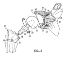
- Figure 1 represents an exploded view of the prosthetic according to one embodiment
- Figure 2 represents a cross-sectional view of an implant shown in Figure 1;
- Figure 3 represents an alternate shoulder prosthetic
- Figures 4 and 5 represent alternate shoulder prosthetics
- Figure 6 represents a side view of an alternate glenoid prosthetic
- Figure 7 represents a side view of an alternate glenoid prosthetic
- Figure 8 represents a perspective view of a constrained glenoid according to the present teachings.
- Figure 9 represents the coupling of an alternate constrained glenoid according to the present teachings.
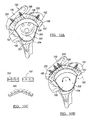
- Figure 10A and 10B represent an alternate partially constrained glenoid prosthetic
- Figure 10C represents optional spacer elements for use with the glenoid prosthetic, as shown in Figures 10A and 10B;
- Figures 10D and 10E represent the coupling of a glenoid base to a prepared scapula
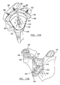
- Figure 11 represents a cross-sectional view of the shoulder shown in Figure 10;
- Figure 12 represents a close up of the insertion of the acromion screw into the glenoid component shown in Figure 11;
- Figure 13 represents an exploded view of the glenoid shown in Figure 11;
- Figures 14A-14C represent a support bracket for the glenoid prosthetic
- Figures 15 and 16 show the use of the support bracket with a reverse shoulder glenoid component.
- Figure 1 represents a glenoid prosthetic 20 according to the teachings of the various embodiments.
- the glenoid prosthetic 20 is coupled to a prepared and resected glenoid 22.
- the prosthetic 20 has a bearing support member 23 having a spherical cup bearing surface 24 and a bearing cup 26.
- the support member 23 further has a constraining wall 28, which is generally positioned on a superior side of the bearing support 23.
- the bearing support 23 defines the generally concave bearing surface 24, which supports the bearing cup 26.
- the bearing cup 26 has a concave bearing surface 25, which is configured to couple to a humeral prosthetic 40.
- the glenoid prosthetic is coupled to the resected glenoid 22 at a coupling surface 38, which has a first convex radius.
- the cup bearing surface has a second concave radius, which can have a valve generally less than the first concave radius.
- a plurality of apertures 32 defined in the bearing support member 23 is a plurality of apertures 32, which function to accept a plurality of bone engaging fasteners 34.
- the glenoid prosthetic 20 is configured to interface with the humeral prosthetic 40, which has a fixation stem 42 and a head 46. Disposed between the head 46 and the fixation stem 42 is a fixation mechanism 48, which is configured to be coupled to a coupling taper 50 defined by the fixation stem 42. As is known, the fixation stem 42 is configured to be implanted into the medullary canal 44 of the resected humerus 46.
- FIG. 2 shows a side sectional view of the prosthetic 20 coupled to the resected glenoid 22.
- the prosthetic 20 is coupled to the resected glenoid 22 using a coupling stem 30 implanted into an aperture 36a within the prepared glenoid.
- a pair of bone fixation screws 34 are driven through the apertures 32 formed in the bearing support 23.
- the screws 34 are driven generally skew to an axis of the stem 30 to augment fixation to the glenoid 22.
- Figure 3 represents a glenoid prosthetic 20 configured to constrain movement of the humeral head 46.
- the prosthetic 20 can have a constraining ring 52, which locks to the bearing support 23 using a snap-ring (now shown).
- the constraining ring 52 has a ring bearing surface 53, which is configured to function as an articulating bearing surface, with respect to the moving humeral head 46.
- the ring 52 further has a ring coupling surface 55, which is configured to be fixably coupled to a bearing support ring coupling surface 57.
- Figures 4 and 5 represent an alternate glenoid prosthetic 60 having augmented fixation.
- the glenoid prosthetic 60 has additional exterior fixation flanges 72 configured to fix the bearing support 23 to the scapula. These flanges 72 can be integral with or coupled to an exterior surface of the bearing support 23.
- the flanges 72 define apertures 78 for accepting fixation screws 80. While the flanges 72 can be placed anywhere radially about the bearing support member 23, it is envisioned that pairs of flanges 72 can be placed radially opposite to each other. The flanges 72 can be elastically or plastically deformed to conform to the shape of the scapula about an exterior surface of the support member 23. It is further envisioned that the flanges 72 can be placed at anterior and posterior positions, or superior 74 and inferior positions 76.
- the bearing support member 23 has a superior ledge 70, which functions to reduce movement of the head 46 in the superior 74 direction.
- the bearing side support walls 68 have a cut out section 73, which allows for extended movement of the humeral head 46 without interference of the humeral coupling member 48 with the bearing support 23 or bearing 66.
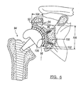
- Figure 6 represents an alternate shoulder prosthetic 90.
- the prosthetic 90 has a glenoid member 92 and a humeral component 94.
- the glenoid member 92 has a glenoid bearing support 96 and a glenoid bearing member 98.
- the glenoid bearing support 96 defines a plurality of support apertures 100, which function with the fixation screws 102 to couple the prosthetic glenoid 90 to the prepared glenoid as previously described.
- the glenoid bearing support 96 and glenoid bearing 98 define a generally constant radius of curvature. ln this regard, the glenoid bearing support 96 and glenoid bearing 98 have first and second portions 104 and 106.
- the first portion 104 is generally placed perpendicular to the surface defined by the natural glenoid. Further, the first portion is generally superiorly located with respect to the second portion 106 and functions to resist the superior movement of the head 46 of the humeral prosthetic 94.
- Figure 7 represents an alternate shoulder prosthetic 120.
- the prosthetic 120 has a glenoid bearing support 122 and a glenoid bearing 124.
- the glenoid support 122 has a first coupling surface 126, which is configured to be mated to a prepared glenoid as previously described.
- the bearing support coupling 126 surface defines a plurality of apertures for accepting of bone engaging fasteners 34.
- the bearing support coupling surface 126 further has a support stem 30.
- the bearing support 122 further has a bearing support bearing surface 128, which is configured to be coupled to the convex bearing exterior surface 130 of bearing 124.
- the bearing 124 has a concave surface having a radius of less than about 32mm. This radius allows for the proper interaction between the bearing surface 132 and an exterior surface of the prosthetic humeral head 134.
- Figures 8 and 9 represent an alternate glenoid prosthetic 150.
- the glenoid prosthetic 150 has a glenoid bearing support 152, which can be coupled to a prepared glenoid as previously described.
- the glenoid bearing support 152 is configured to accept a bearing insert 154, which is configured to mate with a humeral prosthetic 153, as previously shown and described above.
- a pair of flanges 156 and 158 Disposed at superior locations of an external surface 155 of the glenoid bearing support 152 is a pair of flanges 156 and 158. These flanges are fixedly coupled to the exterior surface 155 using a pair of fixation elements 164. The flanges are configured to span the gap between the exterior surface 155 of the glenoid bearing support 152 and the acromion process 160 or the coracoid process 162. Further, the flanges 156 and 158 are fixably coupled to the acromion process 160 and coracoid process 162 using a pair of bone fixation screws 164, which are disposed through a pair of apertures defined within the flanges 156 and 158.
- the pair of flanges 156 and 158 can take the form of tubular members 174. These tubular members 174 defined apertures 176, which function to accept threaded fasteners 178 disposed therethrough.
- the fasteners 178 are further disposed through holes 180 defined in the acromion process 160 and coracoid process 162.
- the end of the fasteners 178 can be fixed using a secondary fastener, such as nut 182 or can be embedded into the acromion or coracoid process 160, 162.
- FIGS 10A-13 show an alternate glenoid prosthetic 190.
- the alternate glenoid prosthetic 190 has a glenoid bearing support 192 and a glenoid bearing member 194.
- the glenoid bearing support 192 has a superior support ledge 196, which defines a plurality of holes 198. As described below, these holes 198 function to accept bone fixation fasteners 200 to allow the coupling of the superior support ledge 196 to the acromion process 160 and/or the coracoid process 162.
- These fasteners can be bone fixation screws or the threaded bolts shown in Figure 9.
- the glenoid bearing support 192 further has a glenoid bearing support tray 202, which defines a plurality of apertures 204 that function to accept bone fixation screws to couple the glenoid bearing support to the resected glenoid.
- the glenoid bearing 194 has a tray bearing surface 195 and a superior support ledge interfacing surface 197.
- the prosthetic glenoid 190 has a bearing support 192 configured to be coupled to the glenoid surface. Disposed between the bearing support 192 and the acromion process or the coracoid process is at least one coupling member 200.
- the coupling member 200 functions to fixably couple the base to either one of the acromion 160 or coracoid process 162.
- the bearing support 192 defines either a spherical or flat insert support surface 197.
- the bearing support 192 further can have a superior support structure or ledge 196 which defines a plurality of apertures 198 configured to accept the coupling members 200. These apertures 198 can either be threaded or unthreaded or can be elongated.
- the bearing support 192 can have a generally L-shaped cross-section.
- the bearing support 192 further defines a plurality of through bores 204 which are configured to accept bone engaging fasteners. It is envisioned that the apertures 204 can be radially spaced about a centrally located bore 212. Further, the apertures 204 can be skew from the centrally located bore 212.
- the coupling member 200 can be a threaded member configured to engage the bone of the acromion 160 or coracoid process 162.
- the threaded coupling member 200 can either be tapered to form a bone engaging screw or can be a bolt configured to couple the superior support structure to a threaded nut (see Figures 12 and 13).
- the coupling member 200 can have a spacer member 205 configured to support the coupling member.
- the spacer member 205 is configured to fill the space between the bearing support 192 or superior support structure 196 and the acromion 160 or coracoid process 162. It is envisioned that the spacer 205 can have varying exterior shapes to engage the surfaces. Measurements by a treating physician can be made using appropriately sized templates.
- the spacer 205 can have a flat surface configured to engage a superior support structure 196. Additionally, it is envisioned that the spacer 205 can have any surface geometry which allows the interface with the support structure 196, or a porous coating to allow boney ingrowth.
- the base can be rotated about the centrally located fixation member and translated to conform to anatomical requirements. After fixing the base to the resected glenoid, the polymer bearing can be inserted. In this way, spacers 205 can be used to augment and support the coupling mechanism 200 to reduce the likelihood of joint dislocations in particular patients.
- FIGS 11 and 12 depict side cross-sectional views of the shoulder prosthetic shown in Figures 10A-10E.
- the glenoid fixation component 206 couples the glenoid bearing support 192 to the resected glenoid 22.
- the glenoid fixation component 206 found on threaded fixation member 210, is positioned through a fixation aperture 208 defined in the glenoid support tray 192.
- a locking mechanism 216 can be used to couple the glenoid bearing 194 to an aperture formed in the glenoid fixation component 206.
- a fixation member 210 is seated within a counterbore within the glenoid bearing support tray 192.
- the threaded fixation member 210 is coupled to an aperture formed in the prepared glenoid 22.
- locking mechanism 214 disposed between the superior support ledge 196 and the glenoid bearing member 194 is a snap locking member 218.
- the snap locking member 218 is located within a notch 220 defined by the superior support ledge 196 and the glenoid bearing 194.
- the bearing surface 195 of the glenoid bearing 194 is configured to slidably accept the articulating surface of the humeral head 224 of the humeral prosthetic 222.
- the humeral head 224 can have an extended articulating surface 226 configured to interface with a superior portion of the bearing surface 195 of the bearing support 194.
- Figure 13 represents an exploded perspective view of the prosthetic shown in Figures 10A-12.
- the glenoid is prepared by first forming the center hole followed by reaming the glenoid surface. As can be seen after preparing the glenoid 22, a plurality of holes 204 are formed after the positioning of the support within the resected glenoid 22.
- the internally threaded sleeve 212 can be positioned within one of the apertures 204 to accept the coupling fastener 210.
- the flange can be coupled using a fixation screw.
- the apertures 204 can be located askew to the axis of the coupling fastener 210.
- Member 200 can have a detail of a square, hex or other geometry to prevent rotation of the internally threaded member 200 during tightening.
- the polymer bearing 194 is coupled to the glenoid bearing support 192 using the snap fastener 218 and locking tab 216.
- a shoulder prosthetic 220 utilizing an inferior support bracket 224.
- the prosthetic 220 is coupled to a resected glenoid using a fixation peg 222.
- the inferior support bracket 224 is used to stabilize the glenoid in situations where there is degradation of the underlying resected glenoid material to enhance fixation and support.
- the inferior support bracket 224 is formed of a curved support member 226, which supports a bearing surface 228 of the glenoid.
- a pair of support flanges 230 are coupled to the curved support member 226 and function to allow the coupling of the inferior support bracket to a metal shell or base using a plurality of fixation members 232.
- the inferior support bracket 224 can be used to support a glenoid component in a reverse shoulder prosthetic 240.
- the reverse shoulder prosthetic 240 utilizes a base member 242, which is coupled to the resected glenoid using a plurality of bone fixation screws 232 disposed through apertures 244 in the base 242.
- the head 246 is coupled to the base using a coupling member 248.
- the inferior support bracket 224 has a curved support member 226, which functions to interface with a curved bearing surface 228 on the base 242 of the reverse shoulder prosthetic 240.
- the pair of support flanges 230 are used to couple the inferior support bracket 224 to the scapula.
Landscapes
- Health & Medical Sciences (AREA)
- Orthopedic Medicine & Surgery (AREA)
- Cardiology (AREA)
- Oral & Maxillofacial Surgery (AREA)
- Transplantation (AREA)
- Engineering & Computer Science (AREA)
- Biomedical Technology (AREA)
- Heart & Thoracic Surgery (AREA)
- Vascular Medicine (AREA)
- Life Sciences & Earth Sciences (AREA)
- Animal Behavior & Ethology (AREA)
- General Health & Medical Sciences (AREA)
- Public Health (AREA)
- Veterinary Medicine (AREA)
- Prostheses (AREA)
Abstract
Disclosed is a set of prosthetic components for use in shoulder replacements. A glenoid component having a base (192) and a plurality of coupling members (200) are disclosed. The coupling members are used to couple the base to at least one of the acromion or coracoid process. A polymer insert (194) which is configured to couple to the base member and articulate with a humeral component is provided.
Description
- The present disclosure relates to a kit of prosthetic components for repair and reconstruction of a portion of a ball-and-socket joint, and more specifically a kit of adapters used to vary the distance between an articulating prosthetic surface and a bone fixation component.
- The shoulder joint is considered to be one of the most complex joints in the body. The scapula, the clavicle, and the humerus all meet at the shoulder joint. The head of the humerus fits into a shallow socket of the scapula called the glenoid fossa to form a mobile joint. When the joint is articulated, the humeral head moves in the glenoid fossa to provide a wide range of motion. The shoulder joint may suffer from various maladies including rheumatoid arthritis, osteoarthritis, rotator cuff arthropathy, vascular necrosis or bone fracture. If severe joint damage occurs and no other means of treatment is found to be effective, then a total or partial shoulder reconstruction may be necessary.
- A shoulder joint prosthesis generally includes the replacement of the ball of the humerus and, optionally, the socket of the shoulder blade with specially designed artificial components. The bio-kinematics, and thus the range of motion in the shoulder vary greatly among prospective patients for reconstructive shoulder surgery. The humeral component typically has a metal shaft or stem with a body portion that is embedded in the resected humerus and a generally hemispherical head portion supported on the stem. The head slidingly engages a glenoid implant on the glenoid fossa. During reconstructive surgery, the components of the prosthesis are matched with the bio-kinematics of the patient in an effort to maintain the natural range of motion of a healthy shoulder joint. Thus, a shoulder prosthesis design must be readily adaptable to a wide range of bio-kinematics for prospective patients.
- In this regard, shoulder prostheses are generally available as either unitary structures or modular components. With unitary shoulder prosthesis, a large inventory of differently sized prostheses must be maintained to accommodate the different bone sizes and joint configurations of the prospective patients. With such unitary shoulder prosthesis, the patient is typically evaluated by x-ray to determine the approximate prostheses size needed for reconstruction. A number of differently sized prostheses are selected as possible candidates based upon this preliminary evaluation. Final selection of the appropriately sized prosthesis is made during the surgery.
- Modular prostheses systems which reduce the need to maintain large inventories of various sized components are well known in the art. Conventionally, the humeral prosthesis includes two components - a humeral stem component and a spherical head releasably coupled to the stem. Alternately, a three component design is known in which the stem and shoulder are interconnected with an adapter. In either of the two-piece or three-piece designs, a radial offset or angulator inclination of the head relative to the stem is provided in individual components. For example, in the three-piece design, an adapter may be configured with a fixed radial offset of 2 millimeters or an angular inclination of 5 degrees. Different radial offsets or angular inclinations are achieved through the use of different adapters or heads. In this regard, conventional modular shoulder prosthesis kits include multiple redundant components such as adapters and heads to achieve a range of prosthetic options.
- While providing an advantage over the unitary design in reducing the number of components needed, a rather large inventory of head components and/or adapter components must be maintained to provide the desired range of geometric configurations with the conventional modular shoulder prostheses. Therefore, there is a need for modular shoulder prostheses which are readily adaptable to provide a range of geometric configurations, i.e. radial offsets, vertical offsets, and angular inclinations while minimizing the number of components required.
- A modular adapter prosthesis kit is provided in accordance with the teachings of the present disclosure. The kit includes a set of coupling members for a glenoid prosthesis, which cooperates with an articulating prosthetic head and fixation component, to provide a range of radial offsets. The coupling members are configured for use with a total shoulder, prosthesis to couple the glenoid to one of the acromion or coracoid process of a patient.
- A kit of prosthetic components is provided for adjustable rotational offset of a base of an articulating surface for a glenoid. The base can include a superior bearing support member having two coupling mechanisms. The height of the first coupling mechanism determines the rotational offset of the base of the articulating surface. The kit can also include a second adapter having at one more coupling mechanisms. The height of one of the coupling mechanisms also determines the rotational offset between the base of the articulating surface and the base of the coupling mechanism of the second adapter.
- The prosthesis kit of the present disclosure provides great flexibility in the adjustment of important bio-kinematic parameters for joint prosthesis systems, while minimizing the number of components required for the modular system. These and other features of the present disclosure will become apparent from the description and especially taken in conjunction with the accompanying exemplary drawings.
- Further areas of applicability of the present invention will become apparent from the detailed description provided hereinafter. It should be understood that the detailed description and specific examples, while indicating the preferred embodiment of the invention, are intended for purposes of illustration only and are not intended to limit the scope of the invention.
- The present invention will become more fully understood from the detailed description and the accompanying drawings, wherein:
- Figure 1 represents an exploded view of the prosthetic according to one embodiment;
- Figure 2 represents a cross-sectional view of an implant shown in Figure 1;
- Figure 3 represents an alternate shoulder prosthetic;
- Figures 4 and 5 represent alternate shoulder prosthetics;
- Figure 6 represents a side view of an alternate glenoid prosthetic;
- Figure 7 represents a side view of an alternate glenoid prosthetic;
- Figure 8 represents a perspective view of a constrained glenoid according to the present teachings;
- Figure 9 represents the coupling of an alternate constrained glenoid according to the present teachings;
- Figure 10A and 10B represent an alternate partially constrained glenoid prosthetic;
- Figure 10C represents optional spacer elements for use with the glenoid prosthetic, as shown in Figures 10A and 10B;
- Figures 10D and 10E represent the coupling of a glenoid base to a prepared scapula;
- Figure 11 represents a cross-sectional view of the shoulder shown in Figure 10;
- Figure 12 represents a close up of the insertion of the acromion screw into the glenoid component shown in Figure 11;
- Figure 13 represents an exploded view of the glenoid shown in Figure 11;
- Figures 14A-14C represent a support bracket for the glenoid prosthetic; and
- Figures 15 and 16 show the use of the support bracket with a reverse shoulder glenoid component.
- The following description of the preferred embodiment(s) is merely exemplary in nature and is in no way intended to limit the invention, its application, or uses.
- Figure 1 represents a
glenoid prosthetic 20 according to the teachings of the various embodiments. Theglenoid prosthetic 20 is coupled to a prepared and resectedglenoid 22. Theprosthetic 20 has abearing support member 23 having a sphericalcup bearing surface 24 and abearing cup 26. Thesupport member 23 further has a constrainingwall 28, which is generally positioned on a superior side of the bearingsupport 23. - As shown in Figure 2, the bearing
support 23 defines the generallyconcave bearing surface 24, which supports the bearingcup 26. The bearingcup 26 has aconcave bearing surface 25, which is configured to couple to ahumeral prosthetic 40. The glenoid prosthetic is coupled to the resected glenoid 22 at acoupling surface 38, which has a first convex radius. The cup bearing surface has a second concave radius, which can have a valve generally less than the first concave radius. Defined in thebearing support member 23 is a plurality ofapertures 32, which function to accept a plurality ofbone engaging fasteners 34. - The
glenoid prosthetic 20 is configured to interface with the humeral prosthetic 40, which has afixation stem 42 and ahead 46. Disposed between thehead 46 and thefixation stem 42 is afixation mechanism 48, which is configured to be coupled to acoupling taper 50 defined by thefixation stem 42. As is known, thefixation stem 42 is configured to be implanted into themedullary canal 44 of the resectedhumerus 46. - Figure 2 shows a side sectional view of the prosthetic 20 coupled to the resected glenoid 22. The prosthetic 20 is coupled to the resected glenoid 22 using a
coupling stem 30 implanted into anaperture 36a within the prepared glenoid. Additionally, a pair of bone fixation screws 34 are driven through theapertures 32 formed in thebearing support 23. In this regard, thescrews 34 are driven generally skew to an axis of thestem 30 to augment fixation to the glenoid 22. - Figure 3 represents a glenoid prosthetic 20 configured to constrain movement of the
humeral head 46. In this regard, the prosthetic 20 can have a constrainingring 52, which locks to thebearing support 23 using a snap-ring (now shown). The constrainingring 52 has aring bearing surface 53, which is configured to function as an articulating bearing surface, with respect to the movinghumeral head 46. Thering 52 further has aring coupling surface 55, which is configured to be fixably coupled to a bearing supportring coupling surface 57. - Figures 4 and 5 represent an alternate glenoid prosthetic 60 having augmented fixation. To this end, the
glenoid prosthetic 60 has additionalexterior fixation flanges 72 configured to fix thebearing support 23 to the scapula. Theseflanges 72 can be integral with or coupled to an exterior surface of the bearingsupport 23. - The
flanges 72 defineapertures 78 for accepting fixation screws 80. While theflanges 72 can be placed anywhere radially about thebearing support member 23, it is envisioned that pairs offlanges 72 can be placed radially opposite to each other. Theflanges 72 can be elastically or plastically deformed to conform to the shape of the scapula about an exterior surface of thesupport member 23. It is further envisioned that theflanges 72 can be placed at anterior and posterior positions, or superior 74 andinferior positions 76. - The
bearing support member 23 has asuperior ledge 70, which functions to reduce movement of thehead 46 in the superior 74 direction. The bearingside support walls 68 have a cut outsection 73, which allows for extended movement of thehumeral head 46 without interference of thehumeral coupling member 48 with the bearingsupport 23 orbearing 66. - Figure 6 represents an
alternate shoulder prosthetic 90. The prosthetic 90 has aglenoid member 92 and ahumeral component 94. Theglenoid member 92 has aglenoid bearing support 96 and aglenoid bearing member 98. Theglenoid bearing support 96 defines a plurality ofsupport apertures 100, which function with the fixation screws 102 to couple the prosthetic glenoid 90 to the prepared glenoid as previously described. - The
glenoid bearing support 96 andglenoid bearing 98 define a generally constant radius of curvature. ln this regard, theglenoid bearing support 96 andglenoid bearing 98 have first andsecond portions first portion 104 is generally placed perpendicular to the surface defined by the natural glenoid. Further, the first portion is generally superiorly located with respect to thesecond portion 106 and functions to resist the superior movement of thehead 46 of thehumeral prosthetic 94. - Figure 7 represents an
alternate shoulder prosthetic 120. The prosthetic 120 has aglenoid bearing support 122 and aglenoid bearing 124. Theglenoid support 122 has afirst coupling surface 126, which is configured to be mated to a prepared glenoid as previously described. In this regard, thebearing support coupling 126 surface defines a plurality of apertures for accepting ofbone engaging fasteners 34. The bearingsupport coupling surface 126 further has asupport stem 30. Thebearing support 122 further has a bearingsupport bearing surface 128, which is configured to be coupled to the convex bearingexterior surface 130 ofbearing 124. Thebearing 124 has a concave surface having a radius of less than about 32mm. This radius allows for the proper interaction between thebearing surface 132 and an exterior surface of the prosthetichumeral head 134. - Figures 8 and 9 represent an alternate
glenoid prosthetic 150. Theglenoid prosthetic 150 has aglenoid bearing support 152, which can be coupled to a prepared glenoid as previously described. Theglenoid bearing support 152 is configured to accept abearing insert 154, which is configured to mate with ahumeral prosthetic 153, as previously shown and described above. - Disposed at superior locations of an
external surface 155 of theglenoid bearing support 152 is a pair offlanges exterior surface 155 using a pair offixation elements 164. The flanges are configured to span the gap between theexterior surface 155 of theglenoid bearing support 152 and theacromion process 160 or thecoracoid process 162. Further, theflanges acromion process 160 andcoracoid process 162 using a pair of bone fixation screws 164, which are disposed through a pair of apertures defined within theflanges - With reference to Figure 9, the pair of
flanges tubular members 174. Thesetubular members 174 definedapertures 176, which function to accept threadedfasteners 178 disposed therethrough. Thefasteners 178 are further disposed throughholes 180 defined in theacromion process 160 andcoracoid process 162. The end of thefasteners 178 can be fixed using a secondary fastener, such asnut 182 or can be embedded into the acromion orcoracoid process - Figures 10A-13 show an alternate
glenoid prosthetic 190. The alternateglenoid prosthetic 190 has aglenoid bearing support 192 and aglenoid bearing member 194. Theglenoid bearing support 192 has asuperior support ledge 196, which defines a plurality ofholes 198. As described below, theseholes 198 function to acceptbone fixation fasteners 200 to allow the coupling of thesuperior support ledge 196 to theacromion process 160 and/or thecoracoid process 162. These fasteners can be bone fixation screws or the threaded bolts shown in Figure 9. - The
glenoid bearing support 192 further has a glenoidbearing support tray 202, which defines a plurality ofapertures 204 that function to accept bone fixation screws to couple the glenoid bearing support to the resected glenoid. Theglenoid bearing 194 has atray bearing surface 195 and a superior supportledge interfacing surface 197. - As shown in Figures 10A-10E, the
prosthetic glenoid 190 has abearing support 192 configured to be coupled to the glenoid surface. Disposed between the bearingsupport 192 and the acromion process or the coracoid process is at least onecoupling member 200. Thecoupling member 200 functions to fixably couple the base to either one of theacromion 160 orcoracoid process 162. - The
bearing support 192 defines either a spherical or flatinsert support surface 197. Thebearing support 192 further can have a superior support structure orledge 196 which defines a plurality ofapertures 198 configured to accept thecoupling members 200. Theseapertures 198 can either be threaded or unthreaded or can be elongated. - The
bearing support 192 can have a generally L-shaped cross-section. Thebearing support 192 further defines a plurality of throughbores 204 which are configured to accept bone engaging fasteners. It is envisioned that theapertures 204 can be radially spaced about a centrally located bore 212. Further, theapertures 204 can be skew from the centrally located bore 212. - The
coupling member 200 can be a threaded member configured to engage the bone of theacromion 160 orcoracoid process 162. The threadedcoupling member 200 can either be tapered to form a bone engaging screw or can be a bolt configured to couple the superior support structure to a threaded nut (see Figures 12 and 13). Thecoupling member 200 can have aspacer member 205 configured to support the coupling member. In this regard, thespacer member 205 is configured to fill the space between the bearingsupport 192 orsuperior support structure 196 and theacromion 160 orcoracoid process 162. It is envisioned that thespacer 205 can have varying exterior shapes to engage the surfaces. Measurements by a treating physician can be made using appropriately sized templates. In this regard, thespacer 205 can have a flat surface configured to engage asuperior support structure 196. Additionally, it is envisioned that thespacer 205 can have any surface geometry which allows the interface with thesupport structure 196, or a porous coating to allow boney ingrowth. - As seen in Figures 10B-10E, the base can be rotated about the centrally located fixation member and translated to conform to anatomical requirements. After fixing the base to the resected glenoid, the polymer bearing can be inserted. In this way,
spacers 205 can be used to augment and support thecoupling mechanism 200 to reduce the likelihood of joint dislocations in particular patients. - Figures 11 and 12 depict side cross-sectional views of the shoulder prosthetic shown in Figures 10A-10E. The
glenoid fixation component 206 couples theglenoid bearing support 192 to the resected glenoid 22. Theglenoid fixation component 206, found on threadedfixation member 210, is positioned through afixation aperture 208 defined in theglenoid support tray 192. Alocking mechanism 216 can be used to couple theglenoid bearing 194 to an aperture formed in theglenoid fixation component 206. As shown in Figure 11, afixation member 210 is seated within a counterbore within the glenoid bearingsupport tray 192. The threadedfixation member 210 is coupled to an aperture formed in the prepared glenoid 22. - As seen in Figure 11,
locking mechanism 214, disposed between thesuperior support ledge 196 and theglenoid bearing member 194 is asnap locking member 218. Thesnap locking member 218 is located within anotch 220 defined by thesuperior support ledge 196 and theglenoid bearing 194. The bearingsurface 195 of theglenoid bearing 194 is configured to slidably accept the articulating surface of thehumeral head 224 of thehumeral prosthetic 222. As best shown in Figure 11, thehumeral head 224 can have an extended articulatingsurface 226 configured to interface with a superior portion of the bearingsurface 195 of thebearing support 194. - Figure 13 represents an exploded perspective view of the prosthetic shown in Figures 10A-12. The glenoid is prepared by first forming the center hole followed by reaming the glenoid surface. As can be seen after preparing the glenoid 22, a plurality of
holes 204 are formed after the positioning of the support within the resected glenoid 22. - The internally threaded
sleeve 212 can be positioned within one of theapertures 204 to accept thecoupling fastener 210. Optionally, the flange can be coupled using a fixation screw. As previously described, theapertures 204 can be located askew to the axis of thecoupling fastener 210. After coupling theglenoid bearing support 192 to the resected glenoid 22, a plurality of holes are disposed through theacromion process 160 andcoracoid process 162 using the holes in thesuperior support ledge 196 as a drilling guide. The fasteners can then be either directly coupled to theacromion process 160 orcoracoid process 162 or a twopiece fastener 200 can be used.Member 200 can have a detail of a square, hex or other geometry to prevent rotation of the internally threadedmember 200 during tightening. At this point, thepolymer bearing 194 is coupled to theglenoid bearing support 192 using thesnap fastener 218 andlocking tab 216. - Referring generally to Figures 14A-16, disclosed is a
shoulder prosthetic 220 utilizing aninferior support bracket 224. The prosthetic 220 is coupled to a resected glenoid using afixation peg 222. Theinferior support bracket 224 is used to stabilize the glenoid in situations where there is degradation of the underlying resected glenoid material to enhance fixation and support. - The
inferior support bracket 224 is formed of acurved support member 226, which supports abearing surface 228 of the glenoid. A pair ofsupport flanges 230 are coupled to thecurved support member 226 and function to allow the coupling of the inferior support bracket to a metal shell or base using a plurality offixation members 232. - As best shown in Figures 15 and 16, the
inferior support bracket 224 can be used to support a glenoid component in areverse shoulder prosthetic 240. Thereverse shoulder prosthetic 240 utilizes abase member 242, which is coupled to the resected glenoid using a plurality of bone fixation screws 232 disposed throughapertures 244 in thebase 242. Thehead 246 is coupled to the base using acoupling member 248. As described with respect to the glenoid prosthetic in Figures 14A-14C, theinferior support bracket 224 has acurved support member 226, which functions to interface with acurved bearing surface 228 on thebase 242 of thereverse shoulder prosthetic 240. The pair ofsupport flanges 230 are used to couple theinferior support bracket 224 to the scapula. - The description of the invention is merely exemplary in nature and, thus, variations that do not depart from the gist of the invention are intended to be within the scope of the invention. Such variations are not to be regarded as a departure from the spirit and scope of the invention.
Claims (28)
- A glenoid component comprising:a base configured to be coupled to a prepared glenoid surface;a first coupling member configured to couple the base to at least one of an acromion process or coracoid process; anda bearing insert coupled to the base.
- The glenoid according to Claim 1 wherein the base defines a generally spherical concave bearing insert support surface.
- The glenoid according to Claim 1 wherein the base defines a generally flat bearing insert support surface.
- The glenoid according to Claim 3 wherein the base defines a superior support structure.
- The glenoid according to Claim 4 wherein the superior support structure defines an aperture, which is configured to accept the first coupling member.
- The glenoid according to Claim 4 wherein the superior support structure defines a plurality of elongated apertures configured to accept the first coupling member.
- The glenoid according to Claim 3 wherein the base has a generally L-shaped cross-section.
- The glenoid according to Claim 3 wherein the flat surface defines an aperture configured to accept a bone engaging screw.
- The glenoid according to Claim 1 wherein the first coupling member is a threaded member configured to engage bone.
- The glenoid according to Claim 1 wherein the coupling member comprises a spacer support.
- The glenoid according to Claim 10 wherein the spacer support defines an aperture configured to annularly support the first coupling member.
- The glenoid according to Claim 10 wherein the spacer support is selected from a group of pre-contoured and flat formable flanges, said flanges defining an attachment mechanism.
- The glenoid according to Claim 1 wherein the first coupling member comprises a plurality of two-piece fasteners.
- A surgical prosthetic comprising:a glenoid support member having a generally L-shaped cross-section, said support member defining a first generally flat bearing support member and a superior bearing support member and a bearing support locking mechanism;a bearing insert having a coupling surface and an articulating surface, said coupling surface having a first coupling mechanism configured to couple to the bearing support locking mechanism; anda second coupling mechanism configured to couple the glenoid support to at least one of an acromion or coracoid process of a patient.
- The prosthetic according to Claim 14 wherein the coupling mechanism comprises a threaded member.
- The prosthetic according to Claim 15 further comprising a spacer element disposed between the glenoid support and at least one of the acromion process or coracoid process.
- The prosthetic according to Claim 10 wherein the spacer element defines a porous metal support surface configured to engage one of the acromion process or coracoid process.
- The prosthetic according to Claim 17 wherein the spacer comprises a bearing support engaging surface.
- The prosthetic according to Claim 18 wherein the bearing support engaging surface is flat.
- The prosthetic according to Claim 14 further comprising a humeral implant.
- The prosthetic according to Claim 14 wherein the generally flat bearing support surface defines a centrally located aperture configured to accept the bone engaging screw.
- The prosthetic according to Claim 21 wherein the centrally located aperture is a slot and wherein said generally flat bearing support comprises a plurality of apertures radially spaced from centrally located aperture.
- The prosthetic according to Claim 21 further comprising a bone engaging fastener defining a bearing support locking mechanism.
- A method of implanting an implant comprising:preparing a glenoid surface;coupling a glenoid base to the prepared glenoid surface;placing a spacer between the glenoid base and at least one of an acromion or coracoid process of a patient;coupling the glenoid base to at least one of an acromion or coracoid process; andfixing a bearing component to the glenoid base.
- The method according to Claim 24 further including measuring the distance between the glenoid base and at least one of the acromion or coracoid process.
- The method according to Claim 25 further including choosing the spacer size based upon the measurement.
- The method according to Claim 26 further including positioning the spacer between the glenoid base and at least one of the acromion or coracoid process.
- The method according to Claim 24 further comprising measuring the distance between glenoid base and one of the acromion or coracoid process.
Applications Claiming Priority (1)
| Application Number | Priority Date | Filing Date | Title |
|---|---|---|---|
| US11/346,543 US7959680B2 (en) | 2006-02-02 | 2006-02-02 | Method and apparatus for performing a shoulder implant procedure |
Publications (1)
| Publication Number | Publication Date |
|---|---|
| EP1815825A1 true EP1815825A1 (en) | 2007-08-08 |
Family
ID=38007317
Family Applications (1)
| Application Number | Title | Priority Date | Filing Date |
|---|---|---|---|
| EP07250378A Withdrawn EP1815825A1 (en) | 2006-02-02 | 2007-01-30 | Shoulder joint prosthesis with acromial and coracoid fixation |
Country Status (2)
| Country | Link |
|---|---|
| US (1) | US7959680B2 (en) |
| EP (1) | EP1815825A1 (en) |
Cited By (11)
| Publication number | Priority date | Publication date | Assignee | Title |
|---|---|---|---|---|
| FR2960418A1 (en) * | 2010-05-31 | 2011-12-02 | Evolutis | Glenoid assembly for shoulder prosthesis, has base plate provided with part for receiving anchoring rod and articulation element, where base plate is provided with another part with fixation arrangements in coracoid process |
| RU2470613C2 (en) * | 2011-01-28 | 2012-12-27 | Общество с ограниченной ответственностью "Эндосервис" | Bipolar endoprosthesis of shoulder joint |
| EP2630935A1 (en) * | 2012-02-27 | 2013-08-28 | Arthrex, Inc. | Glenoid extension block |
| EP2685941A4 (en) * | 2011-03-18 | 2014-07-30 | Depuy Synthes Products Llc | GLENOIDAL REVISION DEVICE AND ASSOCIATED METHOD |
| US9226830B2 (en) | 2011-03-18 | 2016-01-05 | DePuy Synthes Products, Inc. | Device and method for retroversion correction for shoulder arthroplasty |
| US9763679B2 (en) | 2011-03-18 | 2017-09-19 | DePuy Synthes Products, Inc. | Combination driver/anti-rotation handle for shoulder arthroplasty |
| US9820758B2 (en) | 2011-03-18 | 2017-11-21 | DePuy Synthes Products, Inc. | Combination reamer/drill bit for shoulder arthoplasty |
| EP3470021A1 (en) * | 2013-03-08 | 2019-04-17 | Biomet Manufacturing, LLC | Glenoid bone augment |
| IT201800009413A1 (en) * | 2018-10-12 | 2020-04-12 | Limacorporate Spa | Joint prosthesis component, related surgical instruments for bone processing and method of making the prosthesis |
| US12171666B2 (en) | 2019-12-10 | 2024-12-24 | Depuy Ireland Unlimited Company | Metal reinforced acetabular shell liner |
| US12274623B2 (en) | 2019-12-11 | 2025-04-15 | Depuy Ireland Unlimited Company | Ceramic acetabular shell liners with augments |
Families Citing this family (86)
| Publication number | Priority date | Publication date | Assignee | Title |
|---|---|---|---|---|
| US8070820B2 (en) * | 2003-10-08 | 2011-12-06 | Biomet Manufacturing Corp. | Shoulder implant assembly |
| US7918896B2 (en) * | 2004-09-15 | 2011-04-05 | Wright Medical Technology, Inc. | Unitary acetabular cup prosthesis with extension for deficient acetabulum |
| US7922769B2 (en) * | 2004-09-27 | 2011-04-12 | Depuy Products, Inc. | Modular glenoid prosthesis and associated method |
| US7892287B2 (en) * | 2004-09-27 | 2011-02-22 | Depuy Products, Inc. | Glenoid augment and associated method |
| US7927335B2 (en) | 2004-09-27 | 2011-04-19 | Depuy Products, Inc. | Instrument for preparing an implant support surface and associated method |
| US20230080207A1 (en) | 2005-02-25 | 2023-03-16 | Shoulder Innovations, Inc. | Methods and devices for less invasive glenoid replacement |
| US8778028B2 (en) | 2005-02-25 | 2014-07-15 | Shoulder Innovations, Inc. | Methods and devices for less invasive glenoid replacement |
| US20070225821A1 (en) | 2006-03-21 | 2007-09-27 | Axiom Orthopaedics, Inc. | Femoral and humeral stem geometry and implantation method for orthopedic joint reconstruction |
| WO2008069800A1 (en) | 2006-12-07 | 2008-06-12 | Anatol Podolsky | Method and apparatus for total hip replacement |
| US8579985B2 (en) | 2006-12-07 | 2013-11-12 | Ihip Surgical, Llc | Method and apparatus for hip replacement |
| US8974540B2 (en) * | 2006-12-07 | 2015-03-10 | Ihip Surgical, Llc | Method and apparatus for attachment in a modular hip replacement or fracture fixation device |
| US8257363B2 (en) * | 2007-10-12 | 2012-09-04 | Howmedica Osteonics Corp. | Expandable reverse shoulder trial |
| CA2702952C (en) | 2007-10-27 | 2017-01-03 | Parcus Medical, Llc | Suture anchor |
| US8241365B2 (en) | 2008-12-23 | 2012-08-14 | Depuy Products, Inc. | Shoulder prosthesis with vault-filling structure having bone-sparing configuration |
| US9545311B2 (en) | 2009-03-05 | 2017-01-17 | Tornier, Inc. | Glenoid implant anchor post |
| US8231683B2 (en) | 2009-12-08 | 2012-07-31 | Depuy Products, Inc. | Shoulder prosthesis assembly having glenoid rim replacement structure |
| FR2955247B1 (en) | 2010-01-21 | 2013-04-26 | Tornier Sa | GLENOIDAL COMPONENT OF SHOULDER PROSTHESIS |
| US9517139B2 (en) * | 2010-01-15 | 2016-12-13 | DePuy Synthes Products, Inc. | Acromion spacer |
| US9561111B1 (en) * | 2010-05-04 | 2017-02-07 | Floyd G. Goodman | Shoulder joint implant |
| AU2011258241A1 (en) * | 2010-05-26 | 2013-01-10 | Orbis Medical Group Llc | Implantable prostheses |
| US8480750B2 (en) | 2010-11-24 | 2013-07-09 | DePuy Synthes Products, LLC | Modular glenoid prosthesis |
| US8465548B2 (en) | 2010-11-24 | 2013-06-18 | DePuy Synthes Products, LLC | Modular glenoid prosthesis |
| FR2971144A1 (en) | 2011-02-08 | 2012-08-10 | Tornier Sa | GLENOIDAL IMPLANT FOR SHOULDER PROSTHESIS AND SURGICAL KIT |
| US10052114B2 (en) | 2011-07-12 | 2018-08-21 | Materialise, Nv | Shoulder base plate coverage and stability |
| US20150335440A1 (en) | 2011-08-23 | 2015-11-26 | Linares Medical Devices, Llc | Multi-component implant assembly with dual articulating and/or rotating surfaces |
| US8702800B2 (en) * | 2011-08-23 | 2014-04-22 | Linares Medical Devices, Llc | Multi-component shoulder implant assembly with dual articulating surfaces |
| EP2604226A1 (en) | 2011-10-31 | 2013-06-19 | Tornier Orthopedics Ireland Ltd. | Modular reverse shoulder prosthesis |
| US9421106B2 (en) | 2011-12-07 | 2016-08-23 | Howmedica Osteonics Corp. | Reverse shoulder baseplate with alignment guide for glenosphere |
| US9414927B2 (en) | 2011-12-08 | 2016-08-16 | Imds Llc | Shoulder arthroplasty |
| US9439768B2 (en) | 2011-12-08 | 2016-09-13 | Imds Llc | Glenoid vault fixation |
| US8979930B2 (en) | 2012-01-23 | 2015-03-17 | Paul A. Glazer | Orthopedic implants with flexible screws |
| US9498334B2 (en) | 2012-03-27 | 2016-11-22 | DePuy Synthes Products, Inc. | Glenoid defect-filling component |
| ES2627254T3 (en) | 2012-04-23 | 2017-07-27 | Zimmer, Inc. | Glenoidal implant |
| US8906102B2 (en) * | 2012-05-31 | 2014-12-09 | Howmedica Osteonics Corp. | Lateral entry insert for cup trial |
| US8663334B2 (en) * | 2012-05-31 | 2014-03-04 | Howmedica Osteonics Corp. | Lateral entry insert for cup trial |
| EP2897558B1 (en) | 2012-09-21 | 2016-11-16 | Zimmer, Inc. | Shoulder implant system |
| CN104755047B (en) | 2012-10-29 | 2017-05-24 | 东尼尔矫形爱尔兰有限公司 | Systems for Reverse Shoulder Implants |
| US20140128986A1 (en) * | 2012-11-06 | 2014-05-08 | Ihip Surgical, Llc | Monoblock head and neck unit for total hip replacement |
| US9788957B2 (en) | 2012-12-07 | 2017-10-17 | Cleveland Clinic Foundation | Glenoid vault fixation |
| US20140364953A1 (en) * | 2013-06-07 | 2014-12-11 | Daniel P. Tomlinson | Unique baseplate for reverse and total shoulder replacement with added fixation to the scapula |
| WO2015103313A1 (en) | 2013-12-30 | 2015-07-09 | Shoulder Options, Inc. | Instruments and techniques for orienting prosthesis components for joint prostheses |
| US10433969B2 (en) | 2013-12-30 | 2019-10-08 | United Orthopedic Corp. | Arthroplasty implants and methods for orienting joint prosthesis |
| US9962266B2 (en) | 2015-09-11 | 2018-05-08 | Deltoid, Llc | Arthroplasty components |
| EP3777777B1 (en) | 2014-01-03 | 2023-04-05 | Howmedica Osteonics Corp. | Glenoid implant for a shoulder prosthesis |
| GB2525044A (en) * | 2014-04-11 | 2015-10-14 | Biomet Uk Ltd | Prosthesis with fixed or mobile bearing |
| WO2015171962A1 (en) | 2014-05-07 | 2015-11-12 | Bart Bracy | Multipart suture |
| US9681960B2 (en) | 2014-05-16 | 2017-06-20 | Howmedica Osteonics Corp. | Guides for fracture system |
| US10575968B2 (en) | 2014-05-16 | 2020-03-03 | Howmedica Osteonics Corp. | Guides for fracture system |
| US10492926B1 (en) | 2014-09-04 | 2019-12-03 | Shoulder Innovations, Inc. | Alignment guide for humeral or femoral stem replacement prostheses |
| FR3029769A1 (en) | 2014-12-10 | 2016-06-17 | Tornier Sa | KIT FOR A PROSTHESIS OF SHOULDER |
| US10492916B2 (en) * | 2015-03-23 | 2019-12-03 | David Gerald Johnston | Orthopaedic shoulder implant |
| US10722374B2 (en) | 2015-05-05 | 2020-07-28 | Tornier, Inc. | Convertible glenoid implant |
| US10426624B2 (en) | 2015-06-02 | 2019-10-01 | Zimmer, Inc. | Glenosphere guide tool |
| USD835276S1 (en) | 2015-09-11 | 2018-12-04 | United Orthopedic Corporation | Keeled glenoid |
| US10390972B2 (en) | 2016-01-15 | 2019-08-27 | Howmedica Osteonics Corp. | Humeral trial adaptor |
| WO2017184792A1 (en) | 2016-04-19 | 2017-10-26 | Imascap Sas | Pre-operatively planned humeral implant and planning method |
| US11517301B2 (en) | 2016-06-02 | 2022-12-06 | Parcus Medical, Llc | Surgical tool and method of use |
| WO2017210620A1 (en) | 2016-06-02 | 2017-12-07 | Bracy Barton | Suture tool and method of use |
| CN110121301A (en) * | 2016-08-01 | 2019-08-13 | 精密技术公司 | Platform RTSA glenoid prostheses with the modular attachment that can improve initial fixed, fracture reconstruction and joint biomethanics |
| EP4032506B1 (en) | 2016-08-24 | 2023-07-26 | Howmedica Osteonics Corp. | Humeral head implant system |
| US10524921B2 (en) | 2017-03-14 | 2020-01-07 | Floyd G. Goodman | Universal joint implant for shoulder |
| WO2018183484A1 (en) | 2017-03-31 | 2018-10-04 | Tornier, Inc. | Modular humeral head |
| IT201700041420A1 (en) * | 2017-04-13 | 2018-10-13 | Limacorporate Spa | Scapular anchorage for the attachment of a glenoid component of a shoulder joint prosthesis to a scapula with impaired anatomy, and relative method of making said scapular anchorage |
| EP3609440B1 (en) | 2017-04-14 | 2025-01-22 | Shoulder Innovations, Inc. | Total shoulder prosthesis having inset glenoid implant convertible from anatomic to reverse |
| US11510785B2 (en) * | 2017-04-25 | 2022-11-29 | Biomet Manufacturing, Llc | Augmented glenoid with groove |
| KR102788656B1 (en) | 2017-06-29 | 2025-03-28 | 앙코르 메디컬, 엘.피.(디/비/에이 디제이오 서지컬) | Glenosphere with inserts for augmented fixation and related methods |
| EP4497417B1 (en) | 2017-10-16 | 2026-04-29 | Stryker European Operations Limited | Shoulder implants |
| WO2019213073A1 (en) | 2018-04-30 | 2019-11-07 | Shoulder Innovations, Llc | Inset/onlay glenoid, porous coated convertible glenoid, and humeral heads with textured undersides |
| CA3113978C (en) | 2018-10-02 | 2023-10-24 | Tornier, Inc. | Modular humeral head |
| US12370052B2 (en) | 2018-10-02 | 2025-07-29 | Howmedica Osteonics Corp. | Modular humeral head |
| CN109431661B (en) * | 2018-12-27 | 2024-05-28 | 北京爱康宜诚医疗器材有限公司 | Shoulder Prosthesis |
| AU2020237088B2 (en) * | 2019-03-11 | 2025-09-04 | Shoulder Innovations, Inc. | Total reverse shoulder systems and methods |
| US11571310B2 (en) | 2019-04-03 | 2023-02-07 | Catalyst Orthoscience Inc. | Stemmed implant |
| AU2020276186C1 (en) | 2019-05-13 | 2022-07-21 | Howmedica Osteonics Corp. | Glenoid baseplate and implant assemblies |
| US11458019B2 (en) | 2019-06-25 | 2022-10-04 | Depuy Ireland Unlimited Company | Prosthetic implants including a frame for fixation to bone and related methods |
| AU2020204539B2 (en) * | 2019-07-12 | 2024-10-31 | Howmedica Osteonics Corp. | Augmented glenoid design |
| US20220265290A1 (en) | 2019-08-09 | 2022-08-25 | Howmedica Osteonics Corp. | Apparatuses and methods for implanting glenoid prostheses |
| USD938590S1 (en) | 2019-10-01 | 2021-12-14 | Howmedica Osteonics Corp. | Humeral implant |
| US11559402B2 (en) * | 2020-02-04 | 2023-01-24 | Medos International Sarl | Soft glenoid awning and related repair procedures |
| AU2021202801A1 (en) | 2020-05-07 | 2021-11-25 | Howmedica Osteonics Corp. | Stemless metaphyseal humeral implant |
| US12324597B2 (en) | 2021-02-23 | 2025-06-10 | 3D-Side | Methods and systems for arthroplasty |
| JP7620116B2 (en) | 2021-02-26 | 2025-01-22 | ハウメディカ オステオニクス コーポレイション | Glenoid implant components and instruments thereof |
| US11813169B1 (en) * | 2021-04-27 | 2023-11-14 | Zarija Djurovic | Anatomy preserving shoulder joint replacement device with narrow spherical bearing articulator-interpolation segment |
| US20230148085A1 (en) * | 2021-11-10 | 2023-05-11 | 3D Shoulder, Llc | Systems and methods for patient specific shoulder arthroplasty |
| EP4586968A4 (en) * | 2022-09-14 | 2026-04-15 | Arca By Orthoagile Llc | GLENOID REPLACEMENT SYSTEM AND PROCEDURE FOR IMPLANTING THIS GLENOID REPLACEMENT |
| US12440344B2 (en) | 2023-09-21 | 2025-10-14 | Arthrex, Inc. | Constrained orthopaedic implants and methods of repair |
Citations (3)
| Publication number | Priority date | Publication date | Assignee | Title |
|---|---|---|---|---|
| FR2578162A1 (en) * | 1985-03-04 | 1986-09-05 | Rambert Andre | Cup for total prosthesis of the hip or of the shoulder |
| EP1336396A1 (en) * | 2002-02-15 | 2003-08-20 | Tornier Sa | Glenoid component of a shoulder prothesis and total shoulder prothesis incorporating such a component |
| US20040220673A1 (en) * | 2003-04-30 | 2004-11-04 | Pria Paolo Dalla | Inverse prosthesis for the articulation of the shoulder |
Family Cites Families (26)
| Publication number | Priority date | Publication date | Assignee | Title |
|---|---|---|---|---|
| GB1324990A (en) * | 1969-08-25 | 1973-07-25 | Nat Res Dev | Prosthetic shoulder joint devices |
| US3803641A (en) * | 1971-12-30 | 1974-04-16 | V Golyakhovsky | Endoprosthesis of shoulder joint |
| GB1438950A (en) * | 1972-09-04 | 1976-06-09 | Nat Res Dev | Prosthetic devices |
| GB1528471A (en) * | 1975-03-13 | 1978-10-11 | Nat Res Dev | Prosthetic shoulder joint devices |
| US4045825A (en) * | 1976-01-28 | 1977-09-06 | Stroot Jerome H | Humerus prosthesis |
| GB1576111A (en) * | 1976-02-20 | 1980-10-01 | Nat Res Dev | Prosthetic devices |
| CH602091A5 (en) * | 1976-06-03 | 1978-07-31 | Huggler Arnold | |
| US4045826A (en) * | 1977-02-09 | 1977-09-06 | Stroot Jerome H | Glenoid component for shoulder prosthesis |
| US4578081A (en) * | 1982-02-17 | 1986-03-25 | Howmedica International, Inc. | Bone prosthesis |
| FR2545352B1 (en) * | 1983-05-02 | 1990-01-19 | Gabard Jean Jacques | SHOULDER PROSTHESIS |
| US4550450A (en) * | 1984-07-24 | 1985-11-05 | Kinnett James G | Total shoulder prosthesis system |
| US4822370A (en) * | 1986-01-14 | 1989-04-18 | Orthoplant Endoprothetik | Hip joint femoral prosthesis |
| FR2610515A1 (en) * | 1987-02-09 | 1988-08-12 | Jean Lannelongue | SHOULDER PROSTHESIS |
| US4851007A (en) * | 1988-03-18 | 1989-07-25 | Gray Frank B | Femoral component for a hip prosthesis |
| EP0421008B1 (en) * | 1989-10-04 | 1993-06-02 | S + G Implants Gmbh | Femoral hip joint endoprosthesis |
| ATE151621T1 (en) * | 1990-06-06 | 1997-05-15 | Ronald Sekel | HIP PROSTHESIS |
| GB2251795B (en) * | 1991-01-17 | 1995-02-08 | Minnesota Mining & Mfg | Orthopaedic implant |
| FR2685633B1 (en) * | 1991-12-27 | 1998-02-27 | Tornier Sa | MODULAR HUMER PROSTHESIS. |
| DE4232313C1 (en) * | 1992-09-26 | 1994-04-28 | Kubein Meesenburg Dietmar | Artificial joint as an endoprosthesis for the human shoulder joint |
| US5507819A (en) * | 1994-11-02 | 1996-04-16 | Wolf; Eugene M. | Apparatus and method for stabilizing a humeral head in a shoulder |
| US6004353A (en) * | 1997-07-30 | 1999-12-21 | Medidea, Llc | Modular acetabular reconstruction plate |
| US6340370B1 (en) * | 1999-03-10 | 2002-01-22 | Sulzer Orthopedics Ltd. | Modular set of an outer shell for an artificial hip joint cup |
| US6416553B1 (en) * | 1999-03-31 | 2002-07-09 | Biomet, Inc. | Method and apparatus for providing a modular acetabular prosthesis |
| ATE387161T1 (en) * | 2001-01-25 | 2008-03-15 | Smith & Nephew Inc | RETAINING DEVICE FOR HOLDING A PROSTHETIC COMPONENT |
| US6458161B1 (en) * | 2001-02-23 | 2002-10-01 | Biomet, Inc. | Method and apparatus for acetabular reconstruction |
| US20060079963A1 (en) * | 2004-10-07 | 2006-04-13 | Regan Hansen | Semiconstrained shoulder prosthetic for treatment of rotator cuff arthropathy |
-
2006
- 2006-02-02 US US11/346,543 patent/US7959680B2/en not_active Expired - Fee Related
-
2007
- 2007-01-30 EP EP07250378A patent/EP1815825A1/en not_active Withdrawn
Patent Citations (3)
| Publication number | Priority date | Publication date | Assignee | Title |
|---|---|---|---|---|
| FR2578162A1 (en) * | 1985-03-04 | 1986-09-05 | Rambert Andre | Cup for total prosthesis of the hip or of the shoulder |
| EP1336396A1 (en) * | 2002-02-15 | 2003-08-20 | Tornier Sa | Glenoid component of a shoulder prothesis and total shoulder prothesis incorporating such a component |
| US20040220673A1 (en) * | 2003-04-30 | 2004-11-04 | Pria Paolo Dalla | Inverse prosthesis for the articulation of the shoulder |
Cited By (22)
| Publication number | Priority date | Publication date | Assignee | Title |
|---|---|---|---|---|
| FR2960418A1 (en) * | 2010-05-31 | 2011-12-02 | Evolutis | Glenoid assembly for shoulder prosthesis, has base plate provided with part for receiving anchoring rod and articulation element, where base plate is provided with another part with fixation arrangements in coracoid process |
| RU2470613C2 (en) * | 2011-01-28 | 2012-12-27 | Общество с ограниченной ответственностью "Эндосервис" | Bipolar endoprosthesis of shoulder joint |
| US10603053B2 (en) | 2011-03-18 | 2020-03-31 | DePuy Synthes Products, Inc. | Method of using a combination driver/anti-rotation handle for shoulder arthroplasty |
| US11298141B2 (en) | 2011-03-18 | 2022-04-12 | DePuy Synthes Products, Inc. | Method of using a combination driver/anti-rotation handle for shoulder arthroplasty |
| US12383408B2 (en) | 2011-03-18 | 2025-08-12 | DePuy Synthes Products, Inc. | Revision glenoid device method |
| US9226830B2 (en) | 2011-03-18 | 2016-01-05 | DePuy Synthes Products, Inc. | Device and method for retroversion correction for shoulder arthroplasty |
| US9763679B2 (en) | 2011-03-18 | 2017-09-19 | DePuy Synthes Products, Inc. | Combination driver/anti-rotation handle for shoulder arthroplasty |
| US9820758B2 (en) | 2011-03-18 | 2017-11-21 | DePuy Synthes Products, Inc. | Combination reamer/drill bit for shoulder arthoplasty |
| US10172715B2 (en) | 2011-03-18 | 2019-01-08 | DePuy Synthes Products, Inc. | Method of implanting a revision glenoid device |
| US12268400B2 (en) | 2011-03-18 | 2025-04-08 | Depuy Synthes Products, Inc | Combination device for use in preparing a bone to receive a prosthetic component |
| US11903594B2 (en) | 2011-03-18 | 2024-02-20 | Depuy Synthes Products, Inc | Method using a combination reamer/drill bit for shoulder arthroplasty |
| US11369390B2 (en) | 2011-03-18 | 2022-06-28 | DePuy Synthes Products, Inc. | Method using a combination reamer/drill bit for shoulder arthroplasty |
| EP2685941A4 (en) * | 2011-03-18 | 2014-07-30 | Depuy Synthes Products Llc | GLENOIDAL REVISION DEVICE AND ASSOCIATED METHOD |
| US10779842B2 (en) | 2011-03-18 | 2020-09-22 | DePuy Synthes Products, Inc. | Method using combination reamer/drill bit for shoulder arthroplasty |
| US11076963B2 (en) | 2011-03-18 | 2021-08-03 | DePuy Synthes Products, Inc. | Revision glenoid device |
| EP2630935A1 (en) * | 2012-02-27 | 2013-08-28 | Arthrex, Inc. | Glenoid extension block |
| US9216091B2 (en) | 2012-02-27 | 2015-12-22 | Arthrex, Inc. | Glenoid extension block |
| EP3470021A1 (en) * | 2013-03-08 | 2019-04-17 | Biomet Manufacturing, LLC | Glenoid bone augment |
| WO2020074624A1 (en) * | 2018-10-12 | 2020-04-16 | Limacorporate S.P.A. | Joint prosthesis component, related surgical instrumentation for the bone processing and prosthesis manufacturing method |
| IT201800009413A1 (en) * | 2018-10-12 | 2020-04-12 | Limacorporate Spa | Joint prosthesis component, related surgical instruments for bone processing and method of making the prosthesis |
| US12171666B2 (en) | 2019-12-10 | 2024-12-24 | Depuy Ireland Unlimited Company | Metal reinforced acetabular shell liner |
| US12274623B2 (en) | 2019-12-11 | 2025-04-15 | Depuy Ireland Unlimited Company | Ceramic acetabular shell liners with augments |
Also Published As
| Publication number | Publication date |
|---|---|
| US7959680B2 (en) | 2011-06-14 |
| US20070179624A1 (en) | 2007-08-02 |
Similar Documents
| Publication | Publication Date | Title |
|---|---|---|
| US7959680B2 (en) | Method and apparatus for performing a shoulder implant procedure | |
| US20250161061A1 (en) | Shoulder Prosthesis with Variable Inclination Humeral Head Component | |
| US11857427B2 (en) | Implants, systems and methods of using the same | |
| US10603181B2 (en) | Shoulder prosthesis | |
| US9326862B2 (en) | Variable prosthesis | |
| US8052758B1 (en) | Method and apparatus for trialing a modular humeral head | |
| US8070820B2 (en) | Shoulder implant assembly | |
| US8795379B2 (en) | Variable prosthesis | |
| US20170202673A1 (en) | Humeral implant having a floating bearing | |
| US20040064190A1 (en) | Reverse-type humeral prosthesis | |
| EP2685920A1 (en) | Device and method for retroversion correction for shoulder arthroplasty | |
| US20260102255A1 (en) | Reverse shoulder prosthesis and related methods | |
| US20240350274A1 (en) | Glenoid implant and method of installing the same during an orthopaedic shoulder procedure | |
| US20240350275A1 (en) | Augmented glenoid implant and method of installing the same during an orthopaedic shoulder procedure |
Legal Events
| Date | Code | Title | Description |
|---|---|---|---|
| PUAI | Public reference made under article 153(3) epc to a published international application that has entered the european phase |
Free format text: ORIGINAL CODE: 0009012 |
|
| AK | Designated contracting states |
Kind code of ref document: A1 Designated state(s): AT BE BG CH CY CZ DE DK EE ES FI FR GB GR HU IE IS IT LI LT LU LV MC NL PL PT RO SE SI SK TR |
|
| AX | Request for extension of the european patent |
Extension state: AL BA HR MK YU |
|
| AKX | Designation fees paid | ||
| REG | Reference to a national code |
Ref country code: DE Ref legal event code: 8566 |
|
| STAA | Information on the status of an ep patent application or granted ep patent |
Free format text: STATUS: THE APPLICATION IS DEEMED TO BE WITHDRAWN |
|
| 18D | Application deemed to be withdrawn |
Effective date: 20080209 |