EP1815799A1 - Biopsy needle and method for assembling the needle - Google Patents
Biopsy needle and method for assembling the needle Download PDFInfo
- Publication number
- EP1815799A1 EP1815799A1 EP07250439A EP07250439A EP1815799A1 EP 1815799 A1 EP1815799 A1 EP 1815799A1 EP 07250439 A EP07250439 A EP 07250439A EP 07250439 A EP07250439 A EP 07250439A EP 1815799 A1 EP1815799 A1 EP 1815799A1
- Authority
- EP
- European Patent Office
- Prior art keywords
- exterior surface
- insert
- cutter
- tissue
- lumen
- Prior art date
- Legal status (The legal status is an assumption and is not a legal conclusion. Google has not performed a legal analysis and makes no representation as to the accuracy of the status listed.)
- Granted
Links
- 238000001574 biopsy Methods 0.000 title claims abstract description 43
- 238000000034 method Methods 0.000 title claims description 28
- CWYNVVGOOAEACU-UHFFFAOYSA-N Fe2+ Chemical compound [Fe+2] CWYNVVGOOAEACU-UHFFFAOYSA-N 0.000 claims abstract description 22
- 239000012811 non-conductive material Substances 0.000 claims abstract description 19
- 239000000463 material Substances 0.000 claims description 31
- 230000008878 coupling Effects 0.000 claims description 15
- 238000010168 coupling process Methods 0.000 claims description 15
- 238000005859 coupling reaction Methods 0.000 claims description 15
- OKTJSMMVPCPJKN-UHFFFAOYSA-N Carbon Chemical compound [C] OKTJSMMVPCPJKN-UHFFFAOYSA-N 0.000 claims description 12
- 229910052799 carbon Inorganic materials 0.000 claims description 12
- 239000002131 composite material Substances 0.000 claims description 12
- 239000004696 Poly ether ether ketone Substances 0.000 claims description 10
- 229920004738 ULTEM® Polymers 0.000 claims description 10
- 229920001903 high density polyethylene Polymers 0.000 claims description 10
- 239000004700 high-density polyethylene Substances 0.000 claims description 10
- 229920002530 polyetherether ketone Polymers 0.000 claims description 10
- 238000000465 moulding Methods 0.000 claims description 6
- 230000000717 retained effect Effects 0.000 claims description 5
- 238000003825 pressing Methods 0.000 claims description 2
- 238000005452 bending Methods 0.000 abstract description 3
- 239000000523 sample Substances 0.000 description 19
- 238000002595 magnetic resonance imaging Methods 0.000 description 13
- -1 Ultem or Vectra Chemical compound 0.000 description 5
- 238000003780 insertion Methods 0.000 description 4
- 230000037431 insertion Effects 0.000 description 4
- 238000004519 manufacturing process Methods 0.000 description 4
- 238000003466 welding Methods 0.000 description 4
- 239000000853 adhesive Substances 0.000 description 3
- 230000001070 adhesive effect Effects 0.000 description 3
- 238000005520 cutting process Methods 0.000 description 3
- 239000011521 glass Substances 0.000 description 3
- 238000005070 sampling Methods 0.000 description 3
- XEEYBQQBJWHFJM-UHFFFAOYSA-N Iron Chemical compound [Fe] XEEYBQQBJWHFJM-UHFFFAOYSA-N 0.000 description 2
- 229920000106 Liquid crystal polymer Polymers 0.000 description 2
- 239000004977 Liquid-crystal polymers (LCPs) Substances 0.000 description 2
- RTAQQCXQSZGOHL-UHFFFAOYSA-N Titanium Chemical compound [Ti] RTAQQCXQSZGOHL-UHFFFAOYSA-N 0.000 description 2
- HJJVPARKXDDIQD-UHFFFAOYSA-N bromuconazole Chemical compound ClC1=CC(Cl)=CC=C1C1(CN2N=CN=C2)OCC(Br)C1 HJJVPARKXDDIQD-UHFFFAOYSA-N 0.000 description 2
- 238000010276 construction Methods 0.000 description 2
- 238000013461 design Methods 0.000 description 2
- 239000012634 fragment Substances 0.000 description 2
- 229920000642 polymer Polymers 0.000 description 2
- 210000000779 thoracic wall Anatomy 0.000 description 2
- 239000010936 titanium Substances 0.000 description 2
- 229910052719 titanium Inorganic materials 0.000 description 2
- 229920013683 Celanese Polymers 0.000 description 1
- 206010061619 Deformity Diseases 0.000 description 1
- 206010028980 Neoplasm Diseases 0.000 description 1
- 208000006994 Precancerous Conditions Diseases 0.000 description 1
- 229920010741 Ultra High Molecular Weight Polyethylene (UHMWPE) Polymers 0.000 description 1
- 208000027418 Wounds and injury Diseases 0.000 description 1
- 210000003484 anatomy Anatomy 0.000 description 1
- 239000000919 ceramic Substances 0.000 description 1
- 238000013170 computed tomography imaging Methods 0.000 description 1
- 230000006378 damage Effects 0.000 description 1
- 238000003745 diagnosis Methods 0.000 description 1
- 208000037265 diseases, disorders, signs and symptoms Diseases 0.000 description 1
- 208000035475 disorder Diseases 0.000 description 1
- 238000007387 excisional biopsy Methods 0.000 description 1
- 238000000605 extraction Methods 0.000 description 1
- 239000012530 fluid Substances 0.000 description 1
- 230000002068 genetic effect Effects 0.000 description 1
- 230000009931 harmful effect Effects 0.000 description 1
- 238000010562 histological examination Methods 0.000 description 1
- 239000007943 implant Substances 0.000 description 1
- 238000007386 incisional biopsy Methods 0.000 description 1
- 208000014674 injury Diseases 0.000 description 1
- 238000011835 investigation Methods 0.000 description 1
- 229910052742 iron Inorganic materials 0.000 description 1
- 239000007788 liquid Substances 0.000 description 1
- 230000014759 maintenance of location Effects 0.000 description 1
- 230000013011 mating Effects 0.000 description 1
- 239000000155 melt Substances 0.000 description 1
- 210000005036 nerve Anatomy 0.000 description 1
- 238000012633 nuclear imaging Methods 0.000 description 1
- 230000008520 organization Effects 0.000 description 1
- 238000002559 palpation Methods 0.000 description 1
- 239000012188 paraffin wax Substances 0.000 description 1
- 230000007170 pathology Effects 0.000 description 1
- 238000012831 peritoneal equilibrium test Methods 0.000 description 1
- 229920003023 plastic Polymers 0.000 description 1
- 239000004033 plastic Substances 0.000 description 1
- 229920002492 poly(sulfone) Polymers 0.000 description 1
- 238000012636 positron electron tomography Methods 0.000 description 1
- 238000012877 positron emission topography Methods 0.000 description 1
- 238000002360 preparation method Methods 0.000 description 1
- 238000011084 recovery Methods 0.000 description 1
- 229920005989 resin Polymers 0.000 description 1
- 239000011347 resin Substances 0.000 description 1
- 238000010008 shearing Methods 0.000 description 1
- 238000002603 single-photon emission computed tomography Methods 0.000 description 1
- 239000007787 solid Substances 0.000 description 1
- 238000006467 substitution reaction Methods 0.000 description 1
- 238000012360 testing method Methods 0.000 description 1
- 238000001931 thermography Methods 0.000 description 1
- 229920001169 thermoplastic Polymers 0.000 description 1
- 239000004416 thermosoftening plastic Substances 0.000 description 1
- 238000012285 ultrasound imaging Methods 0.000 description 1
Images



Classifications
-
- A—HUMAN NECESSITIES
- A61—MEDICAL OR VETERINARY SCIENCE; HYGIENE
- A61B—DIAGNOSIS; SURGERY; IDENTIFICATION
- A61B10/00—Instruments for taking body samples for diagnostic purposes; Other methods or instruments for diagnosis, e.g. for vaccination diagnosis, sex determination or ovulation-period determination; Throat striking implements
- A61B10/02—Instruments for taking cell samples or for biopsy
- A61B10/0233—Pointed or sharp biopsy instruments
- A61B10/0266—Pointed or sharp biopsy instruments means for severing sample
- A61B10/0275—Pointed or sharp biopsy instruments means for severing sample with sample notch, e.g. on the side of inner stylet
-
- A—HUMAN NECESSITIES
- A61—MEDICAL OR VETERINARY SCIENCE; HYGIENE
- A61B—DIAGNOSIS; SURGERY; IDENTIFICATION
- A61B17/00—Surgical instruments, devices or methods
- A61B2017/00831—Material properties
- A61B2017/00902—Material properties transparent or translucent
-
- A—HUMAN NECESSITIES
- A61—MEDICAL OR VETERINARY SCIENCE; HYGIENE
- A61B—DIAGNOSIS; SURGERY; IDENTIFICATION
- A61B17/00—Surgical instruments, devices or methods
- A61B2017/00831—Material properties
- A61B2017/00902—Material properties transparent or translucent
- A61B2017/00911—Material properties transparent or translucent for fields applied by a magnetic resonance imaging system
Definitions
- the present invention is related generally to biopsy devices and, more particularly, to a needle assembly for use with a biopsy device for acquiring a tissue sample.
- Non-invasive methods for examining tissue include palpation, thermography, PET, SPECT, Nuclear imaging, X-ray, MRI, CT, and ultrasound imaging.
- a biopsy is generally done either in an open procedure or in a percutaneous procedure.
- a scalpel is used by the surgeon to create a large incision in the tissue in order to provide direct viewing and access to the tissue mass of interest. Removal of the entire mass (excisional biopsy) or a part of the mass (incisional biopsy) is performed.
- a needle-like instrument is inserted through a very small incision to access the tissue mass of interest and to obtain a tissue sample for later examination and analysis.
- the advantages of the percutaneous method as compared to the open method are significant: less recovery time for the patient, less pain, less surgical time, lower cost, less risk of injury to adjacent bodily tissues such as nerves, and less disfigurement of the patient's anatomy.
- Aspiration of the tissue through a fine needle generally requires the tissue to be fragmented into pieces small enough to be withdrawn in a fluid medium. This method is less intrusive than other known sampling techniques, but one may only examine cells in the liquid (cytology) and not the cells and the structure (pathology).
- core sampling a core or fragment of tissue is obtained for histological examination and/or genetic tests, which may be done via a frozen or paraffin section.
- the type of biopsy used depends mainly on various factors present in the patient, and no single procedure is ideal for all cases. However, core biopsies seem to be more widely used by physicians.
- a double lumen biopsy needle incorporating vacuum suction to obtain a tissue sample.
- the needle is inserted into a small incision in a patient and is advanced through tissue until the needle is adjacent the tissue of interest.
- a vacuum source may be activated, providing suction inside one of the two lumens.
- the suction is communicated to the second lumen via a passage between the two lumens.
- the second lumen may contain an aperture through which suspicious tissue may be drawn when the vacuum source is activated. Once tissue is drawn into the aperture, the surgeon may advance a cutter through the second lumen in order to excise a sample from the tissue of interest.
- biopsy needles of the type described above are useful in obtaining tissue samples, such needles often generate MRI artifact or present a projectile hazard due to the materials, such as iron, used in their construction.
- MRI artifact may obfuscate a patient's true condition and may diminish the precision with which tissue samples are removed.
- Attempts to construct biopsy needles producing a reduced MRI artifact have been made.
- such biopsy needles may suffer in other categories, such as the ability to withstand significant bending loads, due to the limited number of materials from which a biopsy needle may be constructed and still generate little or no MRI artifact.
- current biopsy needle construction generally involves the welding of components in multiple steps to assemble a complete instrument. Increasing the number of components required for assembly may consequently increase both the manufacturing cost and assembly cost for the instrument. The manufacturing cost may increase due to an increased number of parts that must be designed and constructed and the assembly cost may increase due to the use of a time-consuming welding process that is applied to multiple components.
- a biopsy needle that creates little or no MRI artifact and is non-conductive while still retaining the desirable properties of strength and durability. It would be further advantageous to provide a cost-effective biopsy needle that is easily assembled from a minimal number of components.
- the needle assembly includes an exterior surface configured from a non-ferrous and/or non-conductive material that has a tissue-receiving aperture configured therein.
- the needle assembly further includes an insert constructed from a non-ferrous and/or non-conductive material that is coupled with the exterior surface, where the insert may be configured to divide at least a portion of the lumen defined by the exterior surface into a vacuum lumen and a cutter lumen.
- the needle assembly further includes a cutter, where the cutter is operably configured to translate within the cutter lumen to sever tissue retained within the tissue receiving aperture.
- the insert may be coupled with the exterior surface by pushing the insert into a distal opening in the exterior surface.
- the invention provides a biopsy device comprising: (a) a handle; and (b) a needle assembly attached to said handle, wherein said needle assembly comprises: (i) an exterior surface configured from a non-ferrous and non-conductive material having a tissue-receiving aperture therein; (ii) an insert constructed from a non-ferrous and non-conductive material and attached to said exterior surface, wherein said insert is configured to divide at least a portion of the lumen defined by said exterior surface into a vacuum lumen and a cutter lumen; and (iii) a cutter, wherein said cutter is operably configured to translate within said cutter lumen to sever tissue retained within said tissue receiving aperture.
- the exterior surface may be configured from a high density polyethylene.
- the exterior surface may be configured from an implantable grade polyether-etherketone.
- the insert may comprise a divider adapted to separate the lumen defined by said exterior surface into said cutter lumen and said vacuum lumen.
- the divider may extend along the full length of said exterior surface.
- the divider may extend along a portion of said exterior surface.
- the insert may further comprise longitudinally extending arms having detents, where said detents are operably configured to engage corresponding holes in said exterior surface to form an integral component.
- the cutter may be operably configured to maintain the coupling between said insert and said exterior surface by pressing said insert into said exterior surface such that said detents are unable to disengage said corresponding holes.
- the insert may be coupled with said exterior surface by pushing said insert into the distal end of said exterior surface.
- the insert may be constructed from a material selected from the group consisting of a high density polyethylene and an implantable grade polyether-etherketone.
- the invention further provides a biopsy device comprising: (a) a handle; and (b) a needle assembly attached to said handle, wherein said needle assembly comprises: (i) an exterior surface configured from a non-ferrous and non-conductive material selected from the group consisting of a carbon composite, Vectra, and Ultem, where said exterior surface further includes a tissue-receiving aperture located at the distal end thereof; (ii) an insert constructed from a non-ferrous and non-conductive material and attached to said exterior surface, wherein said insert includes a divider configured to divide at least a portion of the lumen defined by said exterior surface into a vacuum lumen and a cutter lumen, where said insert is coupled with said exterior surface by pushing said insert into the distal end of said exterior surface, where said insert further comprises longitudinally extending arms having detents thereon operably configured to engage holes located on said exterior surface such that engaging said detents and said holes permanently couples said insert and said exterior surface; and (iii) a cutter, wherein said cutter is operably configured to translate
- the invention also provides a method for assembling a biopsy device comprising: (a) providing a handle having a longitudinally extendable cutter tube; (b) molding an exterior surface of a needle assembly from a non-ferrous and non-conductive material; (c) molding an insert from a non-ferrous and non-conductive material; (d) coupling said needle assembly to said handle; (e) pushing said insert into the distal end of said exterior surface; (f) coupling said insert into said exterior surface of said needle assembly; and (g) inserting a cutter.
- the exterior surface may be constructed from a material selected from the group consisting of a carbon composite, a woven carbon composite, Ultem, a high density polyethylene, an implantable grade polyether-etherketone, and Vectra.
- the insert may be constructed from a material selected from the group consisting of a high density polyethylene and an implantable grade polyether-etherketone.
- the method exterior surface may be an annular tube having an opening at the proximal end and the distal end, where said insert is pushed into said distal end.
- the insert may be coupled with said exterior surface by a snap fit.
- the insert may comprise longitudinally extending arms having at least one detent thereon operably configured to couple with at least one corresponding hole located on said exterior surface.
- the coupling between said insert and said exterior surface may be permanent.
- the method may further comprise the step of affixing a tissue-piercing tip to said needle assembly.
- the tissue-piercing tip may be affixed to said insert.
- FIGURE 1 is an isometric view of one version of a hand-held vacuum-assisted biopsy device having a needle assembly;
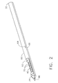
- FIGURE 2 is a left side view of the needle assembly shown in Fig. 1;
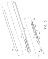
- FIGURE 3 is an exploded view of the needle assembly shown in Fig. 2;
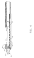
- FIGURE 4 is a longitudinal cross-section view taken along the central axis of the needle assembly shown in Fig. 2;
- FIGURE 5 is an elevated view of an insert of the needle assembly shown in Fig. 3;
- FIGURE 6 is a left side view of the insert shown in Fig. 5;
- FIGURE 7 is an isometric view of the insert shown in Fig. 5.
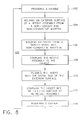
- FIGURE 8 is a flow chart depicting one version of a method for assembling a biopsy device.
- FIG. 1 depicts one version of a biopsy device 10, which may be hand-held and/or vacuum assisted, having a handle 20 detachably or permanently connected to a needle assembly 30 having a proximal portion 32 and a distal portion 34. Together, in one version, they constitute a lightweight, ergonomically-shaped, hand-manipulated biopsy device 10.
- the needle assembly 30 may be part of a disposable probe that may mount on the handle 20.
- the biopsy device 10 may be used in conjunction with an MRI to guide the needle assembly 30. Since the handle 20 may be manipulated by the operator's hand, the operator may steer the needle assembly 30 with great freedom towards the tissue mass of interest. The surgeon has tactile feedback while doing so and may therefore ascertain, to a significant degree, the density and hardness of the tissue being encountered.
- the handle 20 may be held approximately parallel to the chest wall of a patient for obtaining tissue portions closer to the chest wall than may be obtained when the needle assembly 30 is attached to another type of device.
- the needle assembly 30 may be attached to an electromechanical arm, a platform, a table or other suitable support. Such alternative mountings may be used in conjunction with applications in which the needle assembly 30 is guided by stereotactic (x-ray) or MRI modalities.
- handle 20 may include a forward button 36 which may be used to move a cutter 38 (Fig. 4) distally through a cutter lumen 40 to sever a sample of targeted tissue collected in a tissue-receiving port 42.
- Handle 20 may further include a reverse button 44 which may be used to move the cutter 38 proximally through the cutter lumen 40, thereby, for example, moving the tissue sample in the tissue-receiving port 42 to a tissue collection site 46 or retracting the cutter 38 to take another tissue sample.
- a vacuum button 48 on the handle 20 may be used to open or close a first vacuum line (not shown) for communicating suction to a vacuum lumen 52 so as to cause tissue to become disposed within the tissue-receiving port 42 and a second vacuum line (not shown) for communicating axial suction to the cutter 38 to aid in withdrawal of a severed tissue sample.
- a first vacuum line (not shown) for communicating suction to a vacuum lumen 52 so as to cause tissue to become disposed within the tissue-receiving port 42
- a second vacuum line (not shown) for communicating axial suction to the cutter 38 to aid in withdrawal of a severed tissue sample.
- the needle assembly 30 includes an exterior surface 60 coupled with an insert 62.
- the exterior surface 60 may be, for example, an oval or circular tube, cannula, lumen or the like configured from any suitable non-ferrous material, such as a woven carbon composite, a material marketed under the trademark VECTRA held by General Electric, a New York corporation, and/or a material marketed under the trademark ULTEM, held by Celanese, a Delaware corporation, and may be adapted to receive the insert 62 into the distal end thereof.
- Configuring the exterior surface 60 from a non-ferrous material may reduce or eliminate MRI artifact that may obfuscate a patient's true condition and/or diminish the precision with which tissue samples are removed.
- a non-ferrous and non-conductive material such as Ultem or Vectra, may be selected that reduces or eliminates the projectile hazard that may be caused by magnetically reactive materials.
- the non-ferrous material from which the exterior surface 60 is configured is a woven carbon composite material, where the use of such a woven material may reduce or eliminate MRI artifact while preserving the ability of the biopsy device 10 to, for example, withstand significant bending loads.
- the exterior surface 60 or any other suitable component of the biopsy device 10 may be configured from a non-ferrous material, a non-conductive material, an inert material, Ultem, Vectra, a carbon composite, and/or woven carbon composite to provide advantageous strength while reducing or eliminating MRI artifact and/or a projectile hazard.
- the insert 62 may be a molded polymeric component adapted for insertion and retention within the distal end of the exterior surface 60.
- a tissue-piercing tip 86 having a proximal portion and a distal portion, may be disposed on the distal end of the insert 62 to provide the initial incision into the patient.
- the distal portion of the tissue-piercing tip 86 may include a cutting edge 92 of sufficient sharpness to cut through human tissue and thereby aid in moving the needle assembly 30 adjacent the tissue of interest.
- the junction of the tissue-piercing tip 86 and the insert 62 may include a tapered profile therebetween that further assists the needle assembly 30 in moving smoothly through tissue.
- the tissue-piercing tip 86 may comprise a substantially flat blade formed of any suitable material that generates little or no MRI artifact and/or is non-conductive or magnetically inert.
- the tissue-piercing tip 86 may also include tabs or any other suitable coupling means on the proximal portion thereof to aid in the attachment of the tissue-piercing tip 86 to the insert 62.
- the insert 62 may be provided with a divider 64 adapted to substantially divide the lumen defined by the exterior surface 60 into the cutter lumen 40 and the vacuum lumen 52.
- the divider 64 may extend internally along the length of the exterior surface 60 such that the cutter lumen 40 and the vacuum lumen 52 are divided into two distinct lumen.
- the divider 64 may include, for example, a solid molded polymeric distal end attached to a flexible web or the like extending proximally that is operably configured to substantially separate the cutter lumen 40 and the vacuum lumen 52 along the entire length of the exterior surface 60.
- the divider 64 may extend along only a portion of the needle assembly 30 such that the cutter lumen 40 and the vacuum lumen 52 form a single lumen proximally.
- a reduced length divider 64 may be provided for a device where the cutter only translates through the tissue-receiving port 42 of the needle assembly 30.
- the cutter lumen 40 includes a proximal portion and a distal portion.
- the cutter lumen 40 forms a passage for receiving the cutter 38 such that the cutter 38 may be actuated proximally and distally therein to sever tissue.
- An aperture 90 in the insert 62 may be substantially aligned with the tissue-receiving port 42 formed in the exterior surface 60 such that tissue suctioned into the tissue-receiving port 42 may be drawn through the aperture 90 and against the divider 64 prior to being severed.
- the insert 62 may be configured to snap into, or otherwise couple with the exterior surface 60, such that the insert 62 may comprise a portion of the tissue-receiving port 42.
- the tissue-receiving port 42 and aperture 90 may be located adjacent the distal portion of the cutter lumen 40.
- the vacuum lumen 52 located between the divider 64 and the exterior surface 60, includes a proximal portion and a distal portion.
- the cutter lumen 40 may be oriented above the vacuum lumen 52 with the divider 64 disposed therebetween.
- a vacuum source (not shown) may be attached to the vacuum lumen 52, possibly at the proximal portion thereof, to provide suction therethrough. Versions herein may reduce the cost and/or time expenditure associated with welding or manufacturing devices having a greater number of components by efficiently dividing at least a portion the exterior surface 60 into two separate lumen with the insertion of a single component. Reducing the necessary components and providing a more efficient coupling means may ultimately reduce the cost to the patient and/or hospital for such instruments.
- the divider 64 of the insert 62 may also include one or more passages, also called inter-lumen vacuum holes 70, between the cutter lumen 40 and the vacuum lumen 52.
- the inter-lumen vacuum holes 70 may allow that suction to be communicated into the cutter lumen 40.
- the inter-lumen vacuum holes 70 may be located between the cutter lumen 40 and the vacuum lumen 52 opposite the tissue-receiving port 42.
- the insert 62 may further include a cutter stop 72 located in the cutter lumen 40 distal to the tissue-receiving port 42. In one version, the cutter stop 72 aids in severing of the tissue and reduces the potential of tissue fragments becoming lodged in the tip of the insert 62.
- the insert 62 may be affixed to the exterior surface 60 by any suitable coupling means including, for example, a press fit, an adhesive, or with tabs or detents that mate or the like to form a secure connection.
- the insert 62 is provided with arms 66 extending parallel to the longitudinal axis of the exterior surface 60, the arms 66 having a proximal end and a distal end. At about the proximal end of the arms 66, there may be positioned one or a plurality of detents 68 operably configured to mate with one or a plurality of corresponding holes 69 in the exterior surface 60.
- the detents 68 may be configured with any suitable shape or design such as, for example, an oval or elongated shape that may reduce the probability of shearing during use.
- the insert 62 may be pushed into the distal end of the exterior surface 60 until the detents 68 engage the holes 69.
- the arms 66 may be pressed inward slightly upon insertion of the insert 62, such that when the detents 68 reach the holes 69, the arms 66 are biased to push the detents 68 into the holes 69, thereby coupling the two components.
- the cutter 38 may be used to insure that the insert 62 remains secured to the exterior surface 60. For example, when the cutter 38 is positioned immediately proximal of the tissue receiving port 42 in preparation for cutting, the cutter 38 may constrain the arms 66 against the exterior surface 60, thereby preventing the detents 68 from disengaging the holes 69.
- Versions herein include affixing any suitable insert 62 to the needle assembly 30 by placing, for example, the insert 62 into the distal end of the exterior surface 60. Affixing the insert 62 to the exterior surface 60 in a simple two component connection may reduce the cost and/or time expenditure associated with welding or manufacturing a device having a greater number of components.
- the coupling between the insert 62 and exterior surface 60 may be detachable or permanent.
- versions of the insert 62, the outer surface 60, and the connection therebetween are disclosed by way of example only and are not intended to be limiting in any way.
- the insert 62 may have any configuration or design suitable for cooperating with the exterior surface 60 to sample tissue. It is further contemplated that the insert 62 and the exterior surface 60 may be molded as a single integral component.
- the needle assembly 30 may be inserted into a small incision in the body.
- the tissue-piercing tip 86 helps the needle assembly 30 penetrate through tissue until the distal portion 34 of the needle assembly 30 is located adjacent the tissue of interest.
- the tissue-piercing tip 86 may help to minimize tissue drag experienced during insertion and extraction of the needle assembly 30.
- the cutter 38 may have a bore therethrough and may be attached proximally to the second vacuum line (not shown), thereby providing the cutter 38 with axial suction when activated.
- axial suction may assist in pulling the tissue sample through the cutter lumen 40.
- the sample may be cleared into, for example, a tissue collection site 46 (FIG. 1) located on the handle 20 or an adjacent platform.
- another sample may be obtained by applying vacuum to draw a sample into the tissue-receiving port 42 and advancing the cutter 38 to sever the sample. This procedure may be repeated until the desired number of samples has been acquired.
- the tissue-piercing tip 86 may be formed of a material providing sufficient strength and rigidity to allow it to move through tissue with minimal deflection such as, for example, titanium.
- the tissue-piercing tip 86 including the above-described features included thereon, may be stamped or otherwise configured from any suitable material including, for example, MRI compatible and non-conductive resins such as Ultem and Vectra.
- the tissue-piercing tip 86 may also be formed from ceramics or glass.
- the cutting edge 92 may be sharpened by any suitable method known in the art.
- the tissue-piercing tip 86 may be welded to the insert 62.
- tissue-piercing tip 86 may be attached to the insert 62 through any suitable method known in the art that provides satisfactory strength of attachment between the tissue-piercing tip 86 and the insert 62 including, but not limited to, adhesive, press-fit, or screws.
- the insert 62 material may be selected from materials including, but not limited to, Ultem, Vectra, plastics, thermoplastics, thermoresins, polymers, and/or combinations thereof. Additionally, the insert 62 may be configured from a biomedically implantable or compatible material such that, should small pieces of the insert 62 be sheared by the cutter 38, the pieces will not have a harmful effect on the patient if left therein.
- the molded features may be formed of a liquid crystal polymer, a glass reinforced polymer, titanium, and/or polysulfone.
- One suitable material is a glass reinforced liquid crystal polymer such as VECTRA A130 available from Ticona Corp.
- the injected material may have a melt flow index of at least about 10 grams/minute and, more particularly, of at least about 15 grams/minute.
- the molded features may be formed of a high density polyethylene (HDPE) or ultra high molecular weight polyethylene (UHMWPE) used in hip implants or implantable grade polyether-etherketone (PEEK).
- HDPE high density polyethylene
- UHMWPE ultra high molecular weight polyethylene
- PEEK implantable grade polyether-etherketone
- FIG. 8 illustrates one version of a method 100 for assembling a biopsy device.
- Step 102 of the method 100 includes providing a handle with a longitudinally extendable cutter tube such as, for example, the handle 20 disclosed herein. It will be appreciated that any suitable handle, such as a purely mechanical handle, may be substituted for the handle 20.
- Step 104 of the method 100 includes molding or otherwise creating an exterior surface 60 from a non-ferrous and/or non-conductive material such as, for example, a carbon composite, a woven carbon composite, Ultem, a high density polyethylene (HDPE), an implantable grade polyether-etherketone (PEEK), and/or Vectra.
- HDPE high density polyethylene
- PEEK implantable grade polyether-etherketone
- Step 106 of the method 100 includes molding or otherwise creating an insert 62 from a non-ferrous and/or non-conductive material such as, for example, a polymeric, a carbon composite, a woven carbon composite, Ultem, and/or Vectra.
- Step 108 of the method 100 includes coupling the needle assembly to the handle, where step 108 may include permanently or detachably coupling the exterior surface 60 to the handle 20.
- Step 110 of the method 100 includes pushing the insert 62 into, for example, a distal opening in the exterior surface 60.
- Step 112 includes coupling the exterior surface 60 with the insert 62 by providing a snap fit, by mating corresponding holes and detents located on the exterior surface 60 and the insert 62, by providing an adhesive, and/or by any other suitable connection means.
- Step 114 includes inserting or otherwise providing the needle assembly 30 with a cutter 38 operably configured to cut tissue samples.
Landscapes
- Health & Medical Sciences (AREA)
- Life Sciences & Earth Sciences (AREA)
- Surgery (AREA)
- Animal Behavior & Ethology (AREA)
- Biomedical Technology (AREA)
- Heart & Thoracic Surgery (AREA)
- Medical Informatics (AREA)
- Molecular Biology (AREA)
- Pathology (AREA)
- Engineering & Computer Science (AREA)
- General Health & Medical Sciences (AREA)
- Public Health (AREA)
- Veterinary Medicine (AREA)
- Surgical Instruments (AREA)
- Magnetic Resonance Imaging Apparatus (AREA)
- Electrotherapy Devices (AREA)
Abstract
The needle comprises an insert which divides the needle lumen into a vacuum lumen and a cutter lumen.
Description
- The present invention is related generally to biopsy devices and, more particularly, to a needle assembly for use with a biopsy device for acquiring a tissue sample.
- The diagnosis and treatment of patients with cancerous tumors, pre-malignant conditions, and other disorders has long been an area of intense investigation. Non-invasive methods for examining tissue include palpation, thermography, PET, SPECT, Nuclear imaging, X-ray, MRI, CT, and ultrasound imaging. When the physician suspects that tissue may contain cancerous cells, a biopsy is generally done either in an open procedure or in a percutaneous procedure. For an open procedure, a scalpel is used by the surgeon to create a large incision in the tissue in order to provide direct viewing and access to the tissue mass of interest. Removal of the entire mass (excisional biopsy) or a part of the mass (incisional biopsy) is performed. For a percutaneous biopsy, a needle-like instrument is inserted through a very small incision to access the tissue mass of interest and to obtain a tissue sample for later examination and analysis.
- The advantages of the percutaneous method as compared to the open method are significant: less recovery time for the patient, less pain, less surgical time, lower cost, less risk of injury to adjacent bodily tissues such as nerves, and less disfigurement of the patient's anatomy.
- Generally, there are two ways to percutaneously obtain a portion of tissue from within the body: aspiration and core sampling. Aspiration of the tissue through a fine needle generally requires the tissue to be fragmented into pieces small enough to be withdrawn in a fluid medium. This method is less intrusive than other known sampling techniques, but one may only examine cells in the liquid (cytology) and not the cells and the structure (pathology). In core sampling, a core or fragment of tissue is obtained for histological examination and/or genetic tests, which may be done via a frozen or paraffin section. The type of biopsy used depends mainly on various factors present in the patient, and no single procedure is ideal for all cases. However, core biopsies seem to be more widely used by physicians.
- The following patent documents are incorporated herein by reference for the purpose of illustrating biopsy devices and methods and, to no extent, limit the scope of the invention:
US Patent 5,526,822 issued June 18, 1996 ;US 5,895,401 issued April 20, 1999 ;US Patent 6,086,544 issued July 11, 2000 ;US Patent 6,620,111 issued Sept. 16, 2003 ;US Patent 6,626,849 issued September 30, 2003 ;US Patent 6,638,235 issued Oct 28, 2003 ;US Patent Application 2003/0109803 published June 12, 2003 ;US Patent Application 2003/0199753 published Oct 23, 2003 ;US Patent Application 2003/0199754 published Oct. 23, 2003 ;US Patent Application 2003/0199785 published Oct. 23, 2003 ; andUS Serial Number 08/825,899 filed on April 2, 1997 . - It should be appreciated that any patent, publication, or other disclosure material, in whole or in part, that is said to be incorporated by reference herein is incorporated herein only to the extent that the incorporated material does not conflict with existing definitions, statements, or other disclosure material set forth in this disclosure. As such, and to the extent necessary, the disclosure as explicitly set forth herein supersedes any conflicting material incorporated herein by reference. Any material, or portion thereof, that is said to be incorporated by reference herein, but which conflicts with existing definitions, statements, or other disclosure material set forth herein will only be incorporated to the extent that no conflict arises between that incorporated material and the existing disclosure material.
- The use of a double lumen biopsy needle incorporating vacuum suction to obtain a tissue sample is known in the art. With devices of this type, the needle is inserted into a small incision in a patient and is advanced through tissue until the needle is adjacent the tissue of interest. At that point, a vacuum source may be activated, providing suction inside one of the two lumens. The suction is communicated to the second lumen via a passage between the two lumens. The second lumen may contain an aperture through which suspicious tissue may be drawn when the vacuum source is activated. Once tissue is drawn into the aperture, the surgeon may advance a cutter through the second lumen in order to excise a sample from the tissue of interest.
- While biopsy needles of the type described above are useful in obtaining tissue samples, such needles often generate MRI artifact or present a projectile hazard due to the materials, such as iron, used in their construction. MRI artifact may obfuscate a patient's true condition and may diminish the precision with which tissue samples are removed. Attempts to construct biopsy needles producing a reduced MRI artifact have been made. However, such biopsy needles may suffer in other categories, such as the ability to withstand significant bending loads, due to the limited number of materials from which a biopsy needle may be constructed and still generate little or no MRI artifact.
- Additionally, current biopsy needle construction generally involves the welding of components in multiple steps to assemble a complete instrument. Increasing the number of components required for assembly may consequently increase both the manufacturing cost and assembly cost for the instrument. The manufacturing cost may increase due to an increased number of parts that must be designed and constructed and the assembly cost may increase due to the use of a time-consuming welding process that is applied to multiple components.
- Accordingly, it would be advantageous to provide a biopsy needle that creates little or no MRI artifact and is non-conductive while still retaining the desirable properties of strength and durability. It would be further advantageous to provide a cost-effective biopsy needle that is easily assembled from a minimal number of components.
- Disclosed is a biopsy device having a handle with a needle assembly attached thereto. In one version, the needle assembly includes an exterior surface configured from a non-ferrous and/or non-conductive material that has a tissue-receiving aperture configured therein. The needle assembly further includes an insert constructed from a non-ferrous and/or non-conductive material that is coupled with the exterior surface, where the insert may be configured to divide at least a portion of the lumen defined by the exterior surface into a vacuum lumen and a cutter lumen. The needle assembly further includes a cutter, where the cutter is operably configured to translate within the cutter lumen to sever tissue retained within the tissue receiving aperture. The insert may be coupled with the exterior surface by pushing the insert into a distal opening in the exterior surface.
- In particular, the invention provides a biopsy device comprising: (a) a handle; and (b) a needle assembly attached to said handle, wherein said needle assembly comprises: (i) an exterior surface configured from a non-ferrous and non-conductive material having a tissue-receiving aperture therein; (ii) an insert constructed from a non-ferrous and non-conductive material and attached to said exterior surface, wherein said insert is configured to divide at least a portion of the lumen defined by said exterior surface into a vacuum lumen and a cutter lumen; and (iii) a cutter, wherein said cutter is operably configured to translate within said cutter lumen to sever tissue retained within said tissue receiving aperture.
- The exterior surface may be configured from a high density polyethylene.
- The exterior surface may be configured from an implantable grade polyether-etherketone.
- The insert may comprise a divider adapted to separate the lumen defined by said exterior surface into said cutter lumen and said vacuum lumen.
- The divider may extend along the full length of said exterior surface.
- The divider may extend along a portion of said exterior surface.
- The insert may further comprise longitudinally extending arms having detents, where said detents are operably configured to engage corresponding holes in said exterior surface to form an integral component.
- The cutter may be operably configured to maintain the coupling between said insert and said exterior surface by pressing said insert into said exterior surface such that said detents are unable to disengage said corresponding holes.
- The insert may be coupled with said exterior surface by pushing said insert into the distal end of said exterior surface.
- The insert may be constructed from a material selected from the group consisting of a high density polyethylene and an implantable grade polyether-etherketone.
- The invention further provides a biopsy device comprising: (a) a handle; and (b) a needle assembly attached to said handle, wherein said needle assembly comprises: (i) an exterior surface configured from a non-ferrous and non-conductive material selected from the group consisting of a carbon composite, Vectra, and Ultem, where said exterior surface further includes a tissue-receiving aperture located at the distal end thereof; (ii) an insert constructed from a non-ferrous and non-conductive material and attached to said exterior surface, wherein said insert includes a divider configured to divide at least a portion of the lumen defined by said exterior surface into a vacuum lumen and a cutter lumen, where said insert is coupled with said exterior surface by pushing said insert into the distal end of said exterior surface, where said insert further comprises longitudinally extending arms having detents thereon operably configured to engage holes located on said exterior surface such that engaging said detents and said holes permanently couples said insert and said exterior surface; and (iii) a cutter, wherein said cutter is operably configured to translate within said cutter lumen to sever tissue retained within said tissue receiving aperture.
- The invention also provides a method for assembling a biopsy device comprising: (a) providing a handle having a longitudinally extendable cutter tube; (b) molding an exterior surface of a needle assembly from a non-ferrous and non-conductive material; (c) molding an insert from a non-ferrous and non-conductive material; (d) coupling said needle assembly to said handle; (e) pushing said insert into the distal end of said exterior surface; (f) coupling said insert into said exterior surface of said needle assembly; and (g) inserting a cutter.
- The exterior surface may be constructed from a material selected from the group consisting of a carbon composite, a woven carbon composite, Ultem, a high density polyethylene, an implantable grade polyether-etherketone, and Vectra.
- The insert may be constructed from a material selected from the group consisting of a high density polyethylene and an implantable grade polyether-etherketone.
- The method exterior surface may be an annular tube having an opening at the proximal end and the distal end, where said insert is pushed into said distal end.
- The insert may be coupled with said exterior surface by a snap fit.
- The insert may comprise longitudinally extending arms having at least one detent thereon operably configured to couple with at least one corresponding hole located on said exterior surface.
- The coupling between said insert and said exterior surface may be permanent.
- The method may further comprise the step of affixing a tissue-piercing tip to said needle assembly.
- The tissue-piercing tip may be affixed to said insert.
- The novel features and steps of the invention are set forth with particularity in the appended claims. The invention itself, however, both as to organization and methods of operation, together with further objects and advantages thereof, may best be understood by reference to the following description, taken in conjunction with the accompanying drawings in which:
- FIGURE 1 is an isometric view of one version of a hand-held vacuum-assisted biopsy device having a needle assembly;
- FIGURE 2 is a left side view of the needle assembly shown in Fig. 1;
- FIGURE 3 is an exploded view of the needle assembly shown in Fig. 2;
- FIGURE 4 is a longitudinal cross-section view taken along the central axis of the needle assembly shown in Fig. 2;
- FIGURE 5 is an elevated view of an insert of the needle assembly shown in Fig. 3;
- FIGURE 6 is a left side view of the insert shown in Fig. 5;
- FIGURE 7 is an isometric view of the insert shown in Fig. 5.
- FIGURE 8 is a flow chart depicting one version of a method for assembling a biopsy device.
- FIG. 1 depicts one version of a
biopsy device 10, which may be hand-held and/or vacuum assisted, having ahandle 20 detachably or permanently connected to aneedle assembly 30 having aproximal portion 32 and adistal portion 34. Together, in one version, they constitute a lightweight, ergonomically-shaped, hand-manipulatedbiopsy device 10. In one aspect, theneedle assembly 30 may be part of a disposable probe that may mount on thehandle 20. Thebiopsy device 10 may be used in conjunction with an MRI to guide theneedle assembly 30. Since thehandle 20 may be manipulated by the operator's hand, the operator may steer theneedle assembly 30 with great freedom towards the tissue mass of interest. The surgeon has tactile feedback while doing so and may therefore ascertain, to a significant degree, the density and hardness of the tissue being encountered. In addition, thehandle 20 may be held approximately parallel to the chest wall of a patient for obtaining tissue portions closer to the chest wall than may be obtained when theneedle assembly 30 is attached to another type of device. Alternatively, theneedle assembly 30 may be attached to an electromechanical arm, a platform, a table or other suitable support. Such alternative mountings may be used in conjunction with applications in which theneedle assembly 30 is guided by stereotactic (x-ray) or MRI modalities. - Still referring to Fig. 1, as controls for obtaining a tissue sample, handle 20 may include a
forward button 36 which may be used to move a cutter 38 (Fig. 4) distally through acutter lumen 40 to sever a sample of targeted tissue collected in a tissue-receivingport 42.Handle 20 may further include areverse button 44 which may be used to move thecutter 38 proximally through thecutter lumen 40, thereby, for example, moving the tissue sample in the tissue-receivingport 42 to atissue collection site 46 or retracting thecutter 38 to take another tissue sample. Avacuum button 48 on thehandle 20 may be used to open or close a first vacuum line (not shown) for communicating suction to avacuum lumen 52 so as to cause tissue to become disposed within the tissue-receivingport 42 and a second vacuum line (not shown) for communicating axial suction to thecutter 38 to aid in withdrawal of a severed tissue sample. It will be appreciated that thehandle 20 is disclosed by way of example only, where it is contemplated that versions of the present invention may be used with any suitable biopsy device. - Referring, in particular, to FIGS. 2-4, the
needle assembly 30 includes anexterior surface 60 coupled with aninsert 62. Theexterior surface 60 may be, for example, an oval or circular tube, cannula, lumen or the like configured from any suitable non-ferrous material, such as a woven carbon composite, a material marketed under the trademark VECTRA held by General Electric, a New York corporation, and/or a material marketed under the trademark ULTEM, held by Celanese, a Delaware corporation, and may be adapted to receive theinsert 62 into the distal end thereof. Configuring theexterior surface 60 from a non-ferrous material may reduce or eliminate MRI artifact that may obfuscate a patient's true condition and/or diminish the precision with which tissue samples are removed. Additionally, a non-ferrous and non-conductive material, such as Ultem or Vectra, may be selected that reduces or eliminates the projectile hazard that may be caused by magnetically reactive materials. In one version, the non-ferrous material from which theexterior surface 60 is configured is a woven carbon composite material, where the use of such a woven material may reduce or eliminate MRI artifact while preserving the ability of thebiopsy device 10 to, for example, withstand significant bending loads. It will be appreciated that theexterior surface 60 or any other suitable component of thebiopsy device 10 may be configured from a non-ferrous material, a non-conductive material, an inert material, Ultem, Vectra, a carbon composite, and/or woven carbon composite to provide advantageous strength while reducing or eliminating MRI artifact and/or a projectile hazard. - Referring, in particular, to FIGS. 4-7, the
insert 62 may be a molded polymeric component adapted for insertion and retention within the distal end of theexterior surface 60. In one aspect, a tissue-piercingtip 86, having a proximal portion and a distal portion, may be disposed on the distal end of theinsert 62 to provide the initial incision into the patient. The distal portion of the tissue-piercingtip 86 may include acutting edge 92 of sufficient sharpness to cut through human tissue and thereby aid in moving theneedle assembly 30 adjacent the tissue of interest. The junction of the tissue-piercingtip 86 and theinsert 62 may include a tapered profile therebetween that further assists theneedle assembly 30 in moving smoothly through tissue. The tissue-piercingtip 86 may comprise a substantially flat blade formed of any suitable material that generates little or no MRI artifact and/or is non-conductive or magnetically inert. The tissue-piercingtip 86 may also include tabs or any other suitable coupling means on the proximal portion thereof to aid in the attachment of the tissue-piercingtip 86 to theinsert 62. - Referring to FIGS. 4-7, one version of an
insert 62 for use with thebiopsy device 10 is illustrated. Theinsert 62 may be provided with adivider 64 adapted to substantially divide the lumen defined by theexterior surface 60 into thecutter lumen 40 and thevacuum lumen 52. Thedivider 64 may extend internally along the length of theexterior surface 60 such that thecutter lumen 40 and thevacuum lumen 52 are divided into two distinct lumen. In one version, thedivider 64 may include, for example, a solid molded polymeric distal end attached to a flexible web or the like extending proximally that is operably configured to substantially separate thecutter lumen 40 and thevacuum lumen 52 along the entire length of theexterior surface 60. Alternatively, thedivider 64, as illustrated, may extend along only a portion of theneedle assembly 30 such that thecutter lumen 40 and thevacuum lumen 52 form a single lumen proximally. For example, a reducedlength divider 64 may be provided for a device where the cutter only translates through the tissue-receivingport 42 of theneedle assembly 30. - The
cutter lumen 40 includes a proximal portion and a distal portion. In one version, thecutter lumen 40 forms a passage for receiving thecutter 38 such that thecutter 38 may be actuated proximally and distally therein to sever tissue. Anaperture 90 in theinsert 62 may be substantially aligned with the tissue-receivingport 42 formed in theexterior surface 60 such that tissue suctioned into the tissue-receivingport 42 may be drawn through theaperture 90 and against thedivider 64 prior to being severed. In one version, theinsert 62 may be configured to snap into, or otherwise couple with theexterior surface 60, such that theinsert 62 may comprise a portion of the tissue-receivingport 42. The tissue-receivingport 42 andaperture 90 may be located adjacent the distal portion of thecutter lumen 40. - In one version, the
vacuum lumen 52, located between thedivider 64 and theexterior surface 60, includes a proximal portion and a distal portion. Thecutter lumen 40 may be oriented above thevacuum lumen 52 with thedivider 64 disposed therebetween. A vacuum source (not shown) may be attached to thevacuum lumen 52, possibly at the proximal portion thereof, to provide suction therethrough. Versions herein may reduce the cost and/or time expenditure associated with welding or manufacturing devices having a greater number of components by efficiently dividing at least a portion theexterior surface 60 into two separate lumen with the insertion of a single component. Reducing the necessary components and providing a more efficient coupling means may ultimately reduce the cost to the patient and/or hospital for such instruments. - The
divider 64 of theinsert 62 may also include one or more passages, also called inter-lumen vacuum holes 70, between thecutter lumen 40 and thevacuum lumen 52. When the vacuum source (not shown) is activated, thereby providing suction in thevacuum lumen 52, the inter-lumen vacuum holes 70 may allow that suction to be communicated into thecutter lumen 40. As best illustrated in FIG. 4, the inter-lumen vacuum holes 70 may be located between thecutter lumen 40 and thevacuum lumen 52 opposite the tissue-receivingport 42. Theinsert 62 may further include acutter stop 72 located in thecutter lumen 40 distal to the tissue-receivingport 42. In one version, thecutter stop 72 aids in severing of the tissue and reduces the potential of tissue fragments becoming lodged in the tip of theinsert 62. - Referring, in particular, back to FIG. 3, the
insert 62 may be affixed to theexterior surface 60 by any suitable coupling means including, for example, a press fit, an adhesive, or with tabs or detents that mate or the like to form a secure connection. In the illustrated version, theinsert 62 is provided witharms 66 extending parallel to the longitudinal axis of theexterior surface 60, thearms 66 having a proximal end and a distal end. At about the proximal end of thearms 66, there may be positioned one or a plurality ofdetents 68 operably configured to mate with one or a plurality of correspondingholes 69 in theexterior surface 60. Thedetents 68 may be configured with any suitable shape or design such as, for example, an oval or elongated shape that may reduce the probability of shearing during use. During assembly, in one version, theinsert 62 may be pushed into the distal end of theexterior surface 60 until thedetents 68 engage theholes 69. Thearms 66 may be pressed inward slightly upon insertion of theinsert 62, such that when thedetents 68 reach theholes 69, thearms 66 are biased to push thedetents 68 into theholes 69, thereby coupling the two components. In one version, thecutter 38 may be used to insure that theinsert 62 remains secured to theexterior surface 60. For example, when thecutter 38 is positioned immediately proximal of thetissue receiving port 42 in preparation for cutting, thecutter 38 may constrain thearms 66 against theexterior surface 60, thereby preventing thedetents 68 from disengaging theholes 69. - Versions herein include affixing any
suitable insert 62 to theneedle assembly 30 by placing, for example, theinsert 62 into the distal end of theexterior surface 60. Affixing theinsert 62 to theexterior surface 60 in a simple two component connection may reduce the cost and/or time expenditure associated with welding or manufacturing a device having a greater number of components. The coupling between theinsert 62 andexterior surface 60 may be detachable or permanent. It will be appreciated that versions of theinsert 62, theouter surface 60, and the connection therebetween are disclosed by way of example only and are not intended to be limiting in any way. It is contemplated that theinsert 62 may have any configuration or design suitable for cooperating with theexterior surface 60 to sample tissue. It is further contemplated that theinsert 62 and theexterior surface 60 may be molded as a single integral component. - In operation, the
needle assembly 30 may be inserted into a small incision in the body. When utilized, the tissue-piercingtip 86 helps theneedle assembly 30 penetrate through tissue until thedistal portion 34 of theneedle assembly 30 is located adjacent the tissue of interest. The tissue-piercingtip 86 may help to minimize tissue drag experienced during insertion and extraction of theneedle assembly 30. Once theneedle assembly 30 is properly positioned relative to the tissue of interest, vacuum suction may be applied to thevacuum lumen 52 via the first vacuum line (not shown). - The
cutter 38 may have a bore therethrough and may be attached proximally to the second vacuum line (not shown), thereby providing thecutter 38 with axial suction when activated. After a sample has been obtained, and before a second sample is drawn into the tissue-receivingport 42, axial suction, if utilized, may assist in pulling the tissue sample through thecutter lumen 40. Once the tissue sample has been withdrawn from thecutter lumen 40, the sample may be cleared into, for example, a tissue collection site 46 (FIG. 1) located on thehandle 20 or an adjacent platform. At that point, another sample may be obtained by applying vacuum to draw a sample into the tissue-receivingport 42 and advancing thecutter 38 to sever the sample. This procedure may be repeated until the desired number of samples has been acquired. - Referring, in particular, back to FIG. 3, the tissue-piercing
tip 86 may be formed of a material providing sufficient strength and rigidity to allow it to move through tissue with minimal deflection such as, for example, titanium. In one version, the tissue-piercingtip 86, including the above-described features included thereon, may be stamped or otherwise configured from any suitable material including, for example, MRI compatible and non-conductive resins such as Ultem and Vectra. The tissue-piercingtip 86 may also be formed from ceramics or glass. Thecutting edge 92 may be sharpened by any suitable method known in the art. The tissue-piercingtip 86 may be welded to theinsert 62. Alternatively, the tissue-piercingtip 86 may be attached to theinsert 62 through any suitable method known in the art that provides satisfactory strength of attachment between the tissue-piercingtip 86 and theinsert 62 including, but not limited to, adhesive, press-fit, or screws. - Referring, in particular, back to FIGS. 5-7, the
insert 62 material may be selected from materials including, but not limited to, Ultem, Vectra, plastics, thermoplastics, thermoresins, polymers, and/or combinations thereof. Additionally, theinsert 62 may be configured from a biomedically implantable or compatible material such that, should small pieces of theinsert 62 be sheared by thecutter 38, the pieces will not have a harmful effect on the patient if left therein. For instance, the molded features may be formed of a liquid crystal polymer, a glass reinforced polymer, titanium, and/or polysulfone. One suitable material is a glass reinforced liquid crystal polymer such as VECTRA A130 available from Ticona Corp. In one version, the injected material may have a melt flow index of at least about 10 grams/minute and, more particularly, of at least about 15 grams/minute. In a further version, the molded features may be formed of a high density polyethylene (HDPE) or ultra high molecular weight polyethylene (UHMWPE) used in hip implants or implantable grade polyether-etherketone (PEEK). - FIG. 8 illustrates one version of a
method 100 for assembling a biopsy device. Step 102 of themethod 100 includes providing a handle with a longitudinally extendable cutter tube such as, for example, thehandle 20 disclosed herein. It will be appreciated that any suitable handle, such as a purely mechanical handle, may be substituted for thehandle 20. Step 104 of themethod 100 includes molding or otherwise creating anexterior surface 60 from a non-ferrous and/or non-conductive material such as, for example, a carbon composite, a woven carbon composite, Ultem, a high density polyethylene (HDPE), an implantable grade polyether-etherketone (PEEK), and/or Vectra. Step 106 of themethod 100 includes molding or otherwise creating aninsert 62 from a non-ferrous and/or non-conductive material such as, for example, a polymeric, a carbon composite, a woven carbon composite, Ultem, and/or Vectra. Step 108 of themethod 100 includes coupling the needle assembly to the handle, wherestep 108 may include permanently or detachably coupling theexterior surface 60 to thehandle 20. Step 110 of themethod 100 includes pushing theinsert 62 into, for example, a distal opening in theexterior surface 60. Step 112 includes coupling theexterior surface 60 with theinsert 62 by providing a snap fit, by mating corresponding holes and detents located on theexterior surface 60 and theinsert 62, by providing an adhesive, and/or by any other suitable connection means. Step 114 includes inserting or otherwise providing theneedle assembly 30 with acutter 38 operably configured to cut tissue samples. - While various versions of the present invention have been shown and described herein, it will be obvious to those skilled in the art that such alternatives are provided by way of example only. Numerous variations, changes, and substitutions will now occur to those skilled in the art without departing from the present invention. Additionally, each component or element may be described in terms of a means for performing the component's function. It will be appreciated that steps discussed in accordance with disclosed methods are not limited to the order in which they are presented in flow charts, in the disclosure, or the like, where any suitable step may be performed at any time or, if desirable, may be eliminated altogether. Accordingly, it is intended that the invention be limited only by the spirit and scope of the appended claims.
Claims (12)
- A biopsy device comprising:(a) a handle; and(b) a needle assembly attached to said handle, wherein said needle assembly comprises;(i) an exterior surface configured from a non-ferrous and non-conductive material having a tissue-receiving aperture therein;(ii) an insert constructed from a non-ferrous and non-conductive material and attached to said exterior surface, wherein said insert is configured to divide at least a portion of the lumen defined by said exterior surface into a vacuum lumen and a cutter lumen; and(iii) a cutter, wherein said cutter is operably configured to translate within said cutter lumen to sever tissue retained within said tissue receiving aperture.
- The biopsy device of Claim 1, wherein said exterior surface is configured from a high density polyethylene.
- The biopsy device of Claim 1, wherein said exterior surface is configured from an implantable grade polyether-etherketone.
- The biopsy device of Claim 1, wherein said insert comprises a divider adapted to separate the lumen defined by said exterior surface into said cutter lumen and said vacuum lumen.
- The biopsy device of Claim 4, wherein said divider extends along the full length of said exterior surface.
- The biopsy device of Claim 4, wherein said divider extends along a portion of said exterior surface.
- The biopsy device of Claim 4, wherein said insert further comprises longitudinally extending arms having detents, where said detents are operably configured to engage corresponding holes in said exterior surface to form an integral component.
- The biopsy device of Claim 7, wherein said cutter is operably configured to maintain the coupling between said insert and said exterior surface by pressing said insert into said exterior surface such that said detents are unable to disengage said corresponding holes.
- The biopsy device of Claim 1, wherein said insert is coupled with said exterior surface by pushing said insert into the distal end of said exterior surface.
- The biopsy device of Claim 9, wherein said insert is constructed from a material selected from the group consisting of a high density polyethylene and an implantable grade polyether-etherketone.
- A biopsy device comprising:(a) a handle; and(b) a needle assembly attached to said handle, wherein said needle assembly comprises;(i) an exterior surface configured from a non-ferrous and non-conductive material selected from the group consisting of a carbon composite, Vectra, and Ultem, where said exterior surface further includes a tissue-receiving aperture located at the distal end thereof;(ii) an insert constructed from a non-ferrous and non-conductive material and attached to said exterior surface, wherein said insert includes a divider configured to divide at least a portion of the lumen defined by said exterior surface into a vacuum lumen and a cutter lumen, where said insert is coupled with said exterior surface by pushing said insert into the distal end of said exterior surface, where said insert further comprises longitudinally extending arms having detents thereon operably configured to engage holes located on said exterior surface such that engaging said detents and said holes permanently couples said insert and said exterior surface; and(iii) a cutter, wherein said cutter is operably configured to translate within said cutter lumen to sever tissue retained within said tissue receiving aperture.
- A method for assembling a biopsy device comprising:(a) providing a handle having a longitudinally extendable cutter tube;(b) molding an exterior surface of a needle assembly from a non-ferrous and non-conductive material;(c) molding an insert from a non-ferrous and non-conductive material;(d) coupling said needle assembly to said handle;(e) pushing said insert into the distal end of said exterior surface;(f) coupling said insert into said exterior surface of said needle assembly; and(g) inserting a cutter.
Applications Claiming Priority (1)
| Application Number | Priority Date | Filing Date | Title |
|---|---|---|---|
| US11/346,716 US7491177B2 (en) | 2006-02-03 | 2006-02-03 | Biopsy needle and method |
Publications (2)
| Publication Number | Publication Date |
|---|---|
| EP1815799A1 true EP1815799A1 (en) | 2007-08-08 |
| EP1815799B1 EP1815799B1 (en) | 2010-10-13 |
Family
ID=38050108
Family Applications (1)
| Application Number | Title | Priority Date | Filing Date |
|---|---|---|---|
| EP07250439A Not-in-force EP1815799B1 (en) | 2006-02-03 | 2007-02-02 | Biopsy needle and method for assembling the needle |
Country Status (9)
| Country | Link |
|---|---|
| US (1) | US7491177B2 (en) |
| EP (1) | EP1815799B1 (en) |
| JP (1) | JP2007203076A (en) |
| CN (1) | CN101011268B (en) |
| AU (1) | AU2007200201B2 (en) |
| BR (1) | BRPI0700218A (en) |
| CA (1) | CA2576352A1 (en) |
| DE (1) | DE602007009732D1 (en) |
| MX (1) | MX2007001406A (en) |
Cited By (2)
| Publication number | Priority date | Publication date | Assignee | Title |
|---|---|---|---|---|
| US10456295B2 (en) | 2012-06-14 | 2019-10-29 | Tel Hashomer Medical Research Infrastructure And Services Ltd. | Medical device, assembly and method for creating a channel in soft tissue |
| US11583442B2 (en) | 2017-04-09 | 2023-02-21 | Sanoculis Ltd. | Device and method for creating a channel in soft tissue |
Families Citing this family (42)
| Publication number | Priority date | Publication date | Assignee | Title |
|---|---|---|---|---|
| JP4260024B2 (en) | 2002-03-19 | 2009-04-30 | バード ダブリン アイティーシー リミティッド | Vacuum biopsy device |
| EP1768571B1 (en) | 2004-07-09 | 2012-03-21 | Bard Peripheral Vascular, Inc. | Firing system for biopsy device |
| JP4955681B2 (en) | 2005-08-10 | 2012-06-20 | シー・アール・バード・インコーポレーテッド | Single insertion multiple sampling biopsy device with linear drive |
| US8267868B2 (en) | 2005-08-10 | 2012-09-18 | C. R. Bard, Inc. | Single-insertion, multiple sample biopsy device with integrated markers |
| WO2007021904A2 (en) | 2005-08-10 | 2007-02-22 | C.R. Bard Inc. | Single-insertion, multiple sampling biopsy device usable with various transport systems and integrated markers |
| US8251917B2 (en) | 2006-08-21 | 2012-08-28 | C. R. Bard, Inc. | Self-contained handheld biopsy needle |
| ATE493074T1 (en) | 2006-10-06 | 2011-01-15 | Bard Peripheral Vascular Inc | TISSUE HANDLING SYSTEM WITH REDUCED OPERATOR EXPOSURE |
| EP3714798A3 (en) | 2006-10-24 | 2020-12-16 | C. R. Bard, Inc. | Large sample low aspect ratio biopsy needle |
| US7618087B2 (en) * | 2007-01-11 | 2009-11-17 | Ford Motor Company | Vehicle having a front end body structure |
| US20080281224A1 (en) * | 2007-05-11 | 2008-11-13 | Johnson Michael E | Biopsy device needle tip |
| US8241225B2 (en) | 2007-12-20 | 2012-08-14 | C. R. Bard, Inc. | Biopsy device |
| US9332973B2 (en) | 2008-10-01 | 2016-05-10 | Covidien Lp | Needle biopsy device with exchangeable needle and integrated needle protection |
| US9186128B2 (en) | 2008-10-01 | 2015-11-17 | Covidien Lp | Needle biopsy device |
| US8968210B2 (en) | 2008-10-01 | 2015-03-03 | Covidien LLP | Device for needle biopsy with integrated needle protection |
| US9782565B2 (en) | 2008-10-01 | 2017-10-10 | Covidien Lp | Endoscopic ultrasound-guided biliary access system |
| US11298113B2 (en) | 2008-10-01 | 2022-04-12 | Covidien Lp | Device for needle biopsy with integrated needle protection |
| WO2010107424A1 (en) | 2009-03-16 | 2010-09-23 | C.R. Bard, Inc. | Biopsy device having rotational cutting |
| ES2690737T3 (en) | 2009-04-15 | 2018-11-22 | C.R. Bard Inc. | Fluid management |
| US8206316B2 (en) | 2009-06-12 | 2012-06-26 | Devicor Medical Products, Inc. | Tetherless biopsy device with reusable portion |
| EP2464294B1 (en) | 2009-08-12 | 2019-10-02 | C.R. Bard Inc. | Biopsy appaparatus having integrated thumbwheel mechanism for manual rotation of biopsy cannula |
| US8430824B2 (en) | 2009-10-29 | 2013-04-30 | Bard Peripheral Vascular, Inc. | Biopsy driver assembly having a control circuit for conserving battery power |
| KR101148187B1 (en) * | 2009-12-03 | 2012-05-23 | 주식회사 엠아이텍 | Biopsy needle device |
| USD639432S1 (en) | 2010-08-31 | 2011-06-07 | Oasis Medical, Inc. | Handle for use with a micro surgical knife |
| US8875405B2 (en) | 2010-04-09 | 2014-11-04 | Oasis Medical, Inc. | Micro surgical knife with safety feature |
| US8801742B2 (en) * | 2011-06-01 | 2014-08-12 | Devicor Medical Products, Inc. | Needle assembly and blade assembly for biopsy device |
| CN103561663B (en) * | 2011-06-01 | 2016-08-31 | 德威科医疗产品公司 | Needle assembly and blade assembly for biopsy device |
| US9955955B2 (en) | 2011-12-05 | 2018-05-01 | Devicor Medical Products, Inc. | Biopsy device with slide-in probe |
| US9486186B2 (en) * | 2011-12-05 | 2016-11-08 | Devicor Medical Products, Inc. | Biopsy device with slide-in probe |
| EP2838435B1 (en) | 2012-04-16 | 2020-03-25 | Hathaway, Jeff M. | Biopsy device |
| ES2875575T3 (en) | 2013-03-20 | 2021-11-10 | Bard Peripheral Vascular Inc | Biopsy device |
| EP3038549B1 (en) | 2013-09-27 | 2019-08-07 | Release Medical, Inc. | Tissue incision device |
| EP3549533B1 (en) | 2013-11-05 | 2020-12-30 | C.R. Bard, Inc. | Biopsy device having integrated vacuum |
| JP6636136B2 (en) | 2015-05-01 | 2020-01-29 | シー・アール・バード・インコーポレーテッドC R Bard Incorporated | Biopsy device |
| WO2017146343A1 (en) * | 2016-02-25 | 2017-08-31 | 백운 | Needle assembly for biopsy |
| KR101820230B1 (en) | 2016-02-26 | 2018-02-28 | 운스메디칼 주식회사 | Biopsy Needle Assembly |
| KR101820229B1 (en) * | 2016-02-25 | 2018-01-18 | 운스메디칼 주식회사 | Biopsy Needle Assembly |
| US10285731B2 (en) | 2017-06-14 | 2019-05-14 | Polygon Medical, Inc. | Polypectomy systems, devices, and methods |
| CN112120741A (en) * | 2019-06-25 | 2020-12-25 | 杭州德柯医疗科技有限公司 | Adsorption head and adsorption device |
| CN111168333A (en) * | 2020-01-17 | 2020-05-19 | 苏州市美新迪斯医疗科技有限公司 | Preparation method of variable-diameter low-resistance biopsy needle device and product thereof |
| EP3973888A1 (en) * | 2020-09-23 | 2022-03-30 | Xaga Surgical AB | Improved biopsy arrangement |
| JP2024082045A (en) * | 2022-12-07 | 2024-06-19 | 株式会社タスク | Biopsy needle and suction member attached to the biopsy needle |
| EP4470477A1 (en) * | 2023-05-30 | 2024-12-04 | Xaga Surgical AB | Composite needle architecture |
Citations (3)
| Publication number | Priority date | Publication date | Assignee | Title |
|---|---|---|---|---|
| US6077230A (en) * | 1998-05-14 | 2000-06-20 | Ethicon Endo-Surgery, Inc. | Biopsy instrument with removable extractor |
| US20020029007A1 (en) * | 1997-09-19 | 2002-03-07 | Bryan Graham W. | Biopsy apparatus and method |
| EP1642533A1 (en) * | 2004-09-29 | 2006-04-05 | Ethicon Endo-Surgery, Inc. | Biopsy apparatus and method |
Family Cites Families (18)
| Publication number | Priority date | Publication date | Assignee | Title |
|---|---|---|---|---|
| US5526822A (en) | 1994-03-24 | 1996-06-18 | Biopsys Medical, Inc. | Method and apparatus for automated biopsy and collection of soft tissue |
| DE19531117C2 (en) | 1995-08-24 | 1999-05-12 | Daum Gmbh | Use of a titanium alloy for instruments for interventional magnetic resonance imaging and methods for the treatment of such instruments |
| US5722477A (en) * | 1995-10-31 | 1998-03-03 | The Children's Factory | Pipe connector assembly with internal locking mechanism |
| US6086544A (en) | 1999-03-31 | 2000-07-11 | Ethicon Endo-Surgery, Inc. | Control apparatus for an automated surgical biopsy device |
| US6758824B1 (en) | 2000-11-06 | 2004-07-06 | Suros Surgical Systems, Inc. | Biopsy apparatus |
| CN2466626Y (en) * | 2001-01-12 | 2001-12-19 | 杜永义 | Biopsy gun for vacuum circular cutting |
| US6620111B2 (en) | 2001-04-20 | 2003-09-16 | Ethicon Endo-Surgery, Inc. | Surgical biopsy device having automatic rotation of the probe for taking multiple samples |
| US6605047B2 (en) * | 2001-09-10 | 2003-08-12 | Vivant Medical, Inc. | Biopsy marker delivery system |
| US6626849B2 (en) * | 2001-11-01 | 2003-09-30 | Ethicon Endo-Surgery, Inc. | MRI compatible surgical biopsy device |
| US7826883B2 (en) | 2002-04-23 | 2010-11-02 | Devicor Medical Products, Inc. | Localization mechanism for an MRI compatible biopsy device |
| US7769426B2 (en) * | 2002-04-23 | 2010-08-03 | Ethicon Endo-Surgery, Inc. | Method for using an MRI compatible biopsy device with detachable probe |
| US20030199753A1 (en) * | 2002-04-23 | 2003-10-23 | Ethicon Endo-Surgery | MRI compatible biopsy device with detachable probe |
| US6981949B2 (en) * | 2002-06-06 | 2006-01-03 | Ethicon Endo-Surgery, Inc. | Perimeter cut biopsy probe |
| US7740597B2 (en) * | 2002-12-11 | 2010-06-22 | Ethicon Endo-Surgery, Inc. | Biopsy device with sample tube |
| US9345456B2 (en) * | 2004-03-24 | 2016-05-24 | Devicor Medical Products, Inc. | Biopsy device |
| US7445739B2 (en) * | 2004-03-24 | 2008-11-04 | Ethicon Endo-Surgery, Inc. | Method of forming a biopsy device |
| EP1761174B1 (en) * | 2004-05-21 | 2009-10-07 | Ethicon Endo-Surgery, Inc. | Mri biopsy apparatus incorporating an imagable penetrating portion |
| US7740596B2 (en) * | 2004-09-29 | 2010-06-22 | Ethicon Endo-Surgery, Inc. | Biopsy device with sample storage |
-
2006
- 2006-02-03 US US11/346,716 patent/US7491177B2/en active Active
-
2007
- 2007-01-18 AU AU2007200201A patent/AU2007200201B2/en not_active Ceased
- 2007-01-26 CA CA002576352A patent/CA2576352A1/en not_active Abandoned
- 2007-02-02 DE DE602007009732T patent/DE602007009732D1/en active Active
- 2007-02-02 JP JP2007024414A patent/JP2007203076A/en active Pending
- 2007-02-02 BR BRPI0700218-1A patent/BRPI0700218A/en not_active IP Right Cessation
- 2007-02-02 EP EP07250439A patent/EP1815799B1/en not_active Not-in-force
- 2007-02-02 MX MX2007001406A patent/MX2007001406A/en active IP Right Grant
- 2007-02-02 CN CN2007100065326A patent/CN101011268B/en not_active Expired - Fee Related
Patent Citations (3)
| Publication number | Priority date | Publication date | Assignee | Title |
|---|---|---|---|---|
| US20020029007A1 (en) * | 1997-09-19 | 2002-03-07 | Bryan Graham W. | Biopsy apparatus and method |
| US6077230A (en) * | 1998-05-14 | 2000-06-20 | Ethicon Endo-Surgery, Inc. | Biopsy instrument with removable extractor |
| EP1642533A1 (en) * | 2004-09-29 | 2006-04-05 | Ethicon Endo-Surgery, Inc. | Biopsy apparatus and method |
Cited By (4)
| Publication number | Priority date | Publication date | Assignee | Title |
|---|---|---|---|---|
| US10456295B2 (en) | 2012-06-14 | 2019-10-29 | Tel Hashomer Medical Research Infrastructure And Services Ltd. | Medical device, assembly and method for creating a channel in soft tissue |
| US11583442B2 (en) | 2017-04-09 | 2023-02-21 | Sanoculis Ltd. | Device and method for creating a channel in soft tissue |
| US11701257B2 (en) | 2017-04-09 | 2023-07-18 | Sanoculis Ltd. | Device and method for creating a channel in soft tissue |
| US11974947B2 (en) | 2017-04-09 | 2024-05-07 | Sanoculis Ltd. | Device and method for creating a channel in soft tissue |
Also Published As
| Publication number | Publication date |
|---|---|
| CN101011268B (en) | 2010-06-16 |
| US20070185411A1 (en) | 2007-08-09 |
| AU2007200201B2 (en) | 2011-09-29 |
| CA2576352A1 (en) | 2007-08-03 |
| AU2007200201A1 (en) | 2007-08-23 |
| JP2007203076A (en) | 2007-08-16 |
| MX2007001406A (en) | 2009-02-12 |
| BRPI0700218A (en) | 2007-11-06 |
| EP1815799B1 (en) | 2010-10-13 |
| US7491177B2 (en) | 2009-02-17 |
| DE602007009732D1 (en) | 2010-11-25 |
| CN101011268A (en) | 2007-08-08 |
Similar Documents
| Publication | Publication Date | Title |
|---|---|---|
| EP1815799B1 (en) | Biopsy needle and method for assembling the needle | |
| EP1676533B1 (en) | Method of manufacturing a needle assembly for use with a biopsy device | |
| EP1319568B1 (en) | An MRI compatible surgical biopsy device having a tip which leaves an artifact | |
| US6626849B2 (en) | MRI compatible surgical biopsy device | |
| JP6078117B2 (en) | Replaceable core biopsy needle | |
| JP4659014B2 (en) | Biological tissue cutting device | |
| US20020138021A1 (en) | Micro-invasive tissue removal device | |
| US20020138020A1 (en) | Micro-invasive breast biopsy device | |
| JP2016032633A (en) | Exchangeable core biopsy needle | |
| US10182798B2 (en) | Exchangeable core biopsy needle | |
| WO2025144097A1 (en) | Tissue biopsy instrument and method of forming the same |
Legal Events
| Date | Code | Title | Description |
|---|---|---|---|
| PUAI | Public reference made under article 153(3) epc to a published international application that has entered the european phase |
Free format text: ORIGINAL CODE: 0009012 |
|
| AK | Designated contracting states |
Kind code of ref document: A1 Designated state(s): AT BE BG CH CY CZ DE DK EE ES FI FR GB GR HU IE IS IT LI LT LU LV MC NL PL PT RO SE SI SK TR |
|
| AX | Request for extension of the european patent |
Extension state: AL BA HR MK YU |
|
| 17P | Request for examination filed |
Effective date: 20080128 |
|
| 17Q | First examination report despatched |
Effective date: 20080303 |
|
| AKX | Designation fees paid |
Designated state(s): DE ES FR GB IT |
|
| GRAP | Despatch of communication of intention to grant a patent |
Free format text: ORIGINAL CODE: EPIDOSNIGR1 |
|
| GRAS | Grant fee paid |
Free format text: ORIGINAL CODE: EPIDOSNIGR3 |
|
| GRAA | (expected) grant |
Free format text: ORIGINAL CODE: 0009210 |
|
| AK | Designated contracting states |
Kind code of ref document: B1 Designated state(s): DE ES FR GB IT |
|
| REG | Reference to a national code |
Ref country code: GB Ref legal event code: FG4D |
|
| REF | Corresponds to: |
Ref document number: 602007009732 Country of ref document: DE Date of ref document: 20101125 Kind code of ref document: P |
|
| RAP2 | Party data changed (patent owner data changed or rights of a patent transferred) |
Owner name: DEVICOR MEDICAL PRODUCTS, INC. |
|
| PG25 | Lapsed in a contracting state [announced via postgrant information from national office to epo] |
Ref country code: ES Free format text: LAPSE BECAUSE OF FAILURE TO SUBMIT A TRANSLATION OF THE DESCRIPTION OR TO PAY THE FEE WITHIN THE PRESCRIBED TIME-LIMIT Effective date: 20110124 |
|
| PLBE | No opposition filed within time limit |
Free format text: ORIGINAL CODE: 0009261 |
|
| STAA | Information on the status of an ep patent application or granted ep patent |
Free format text: STATUS: NO OPPOSITION FILED WITHIN TIME LIMIT |
|
| 26N | No opposition filed |
Effective date: 20110714 |
|
| REG | Reference to a national code |
Ref country code: DE Ref legal event code: R097 Ref document number: 602007009732 Country of ref document: DE Effective date: 20110714 |
|
| REG | Reference to a national code |
Ref country code: FR Ref legal event code: ST Effective date: 20111102 |
|
| REG | Reference to a national code |
Ref country code: GB Ref legal event code: 732E Free format text: REGISTERED BETWEEN 20111124 AND 20111129 |
|
| PG25 | Lapsed in a contracting state [announced via postgrant information from national office to epo] |
Ref country code: IT Free format text: LAPSE BECAUSE OF FAILURE TO SUBMIT A TRANSLATION OF THE DESCRIPTION OR TO PAY THE FEE WITHIN THE PRESCRIBED TIME-LIMIT Effective date: 20101013 |
|
| PG25 | Lapsed in a contracting state [announced via postgrant information from national office to epo] |
Ref country code: FR Free format text: LAPSE BECAUSE OF NON-PAYMENT OF DUE FEES Effective date: 20110228 |
|
| REG | Reference to a national code |
Ref country code: DE Ref legal event code: R082 Ref document number: 602007009732 Country of ref document: DE Representative=s name: MUELLER-BORE & PARTNER PATENTANWAELTE PARTG MB, DE Effective date: 20120524 Ref country code: DE Ref legal event code: R081 Ref document number: 602007009732 Country of ref document: DE Owner name: DEVICOR MEDICAL PRODUCTS, INC., PLEASANT PRAIR, US Free format text: FORMER OWNER: ETHICON ENDO-SURGERY, INC., CINCINNATI, OHIO, US Effective date: 20120524 Ref country code: DE Ref legal event code: R081 Ref document number: 602007009732 Country of ref document: DE Owner name: DEVICOR MEDICAL PRODUCTS, INC., US Free format text: FORMER OWNER: ETHICON ENDO-SURGERY, INC., CINCINNATI, US Effective date: 20120524 |
|
| PGFP | Annual fee paid to national office [announced via postgrant information from national office to epo] |
Ref country code: DE Payment date: 20150226 Year of fee payment: 9 |
|
| PGFP | Annual fee paid to national office [announced via postgrant information from national office to epo] |
Ref country code: GB Payment date: 20150226 Year of fee payment: 9 |
|
| REG | Reference to a national code |
Ref country code: DE Ref legal event code: R119 Ref document number: 602007009732 Country of ref document: DE |
|
| GBPC | Gb: european patent ceased through non-payment of renewal fee |
Effective date: 20160202 |
|
| PG25 | Lapsed in a contracting state [announced via postgrant information from national office to epo] |
Ref country code: DE Free format text: LAPSE BECAUSE OF NON-PAYMENT OF DUE FEES Effective date: 20160901 Ref country code: GB Free format text: LAPSE BECAUSE OF NON-PAYMENT OF DUE FEES Effective date: 20160202 |