EP1814343A1 - Mobile radio base station radio channel setting method - Google Patents
Mobile radio base station radio channel setting method Download PDFInfo
- Publication number
- EP1814343A1 EP1814343A1 EP04822630A EP04822630A EP1814343A1 EP 1814343 A1 EP1814343 A1 EP 1814343A1 EP 04822630 A EP04822630 A EP 04822630A EP 04822630 A EP04822630 A EP 04822630A EP 1814343 A1 EP1814343 A1 EP 1814343A1
- Authority
- EP
- European Patent Office
- Prior art keywords
- radio base
- station
- mobile radio
- mobile
- channel
- Prior art date
- Legal status (The legal status is an assumption and is not a legal conclusion. Google has not performed a legal analysis and makes no representation as to the accuracy of the status listed.)
- Withdrawn
Links
Images



Classifications
-
- H—ELECTRICITY
- H04—ELECTRIC COMMUNICATION TECHNIQUE
- H04W—WIRELESS COMMUNICATION NETWORKS
- H04W16/00—Network planning, e.g. coverage or traffic planning tools; Network deployment, e.g. resource partitioning or cells structures
- H04W16/14—Spectrum sharing arrangements between different networks
- H04W16/16—Spectrum sharing arrangements between different networks for PBS [Private Base Station] arrangements
-
- H—ELECTRICITY
- H04—ELECTRIC COMMUNICATION TECHNIQUE
- H04W—WIRELESS COMMUNICATION NETWORKS
- H04W84/00—Network topologies
- H04W84/02—Hierarchically pre-organised networks, e.g. paging networks, cellular networks, WLAN [Wireless Local Area Network] or WLL [Wireless Local Loop]
- H04W84/04—Large scale networks; Deep hierarchical networks
- H04W84/042—Public Land Mobile systems, e.g. cellular systems
- H04W84/045—Public Land Mobile systems, e.g. cellular systems using private Base Stations, e.g. femto Base Stations, home Node B
-
- H—ELECTRICITY
- H04—ELECTRIC COMMUNICATION TECHNIQUE
- H04W—WIRELESS COMMUNICATION NETWORKS
- H04W92/00—Interfaces specially adapted for wireless communication networks
- H04W92/04—Interfaces between hierarchically different network devices
- H04W92/12—Interfaces between hierarchically different network devices between access points and access point controllers
Definitions
- the present invention relates to a method of setting a radio channel of a mobile radio base-station that is movable and used in a radio communication system established in a limited area or indoors.
- An indoor radio communication system employs a configuration in which a radio-wave reaching distance is limited from about a few meters to a few tens of meters by limiting transmission power and radio base stations are arranged in the entire indoor service area at intervals of a few meters and a few tens of meters to use assigned radio frequency resources effectively to the maximum extent possible.
- radio channels need to be set to avoid mutual interference between frequencies of channels of the radio base stations.
- the method of assigning radio channels to radio base stations is broadly classified into two types.
- One is fixedly setting a frequency of a radio channel considering an assignment of radio channels to neighboring radio base stations and radio wave propagation at the time of establishing a radio base station (hereinafter, “fixed radio-channel setting").
- the other is equally assigning a set of available frequencies to base stations in advance, and determining a frequency to be used in each radio base station at the time of activating the radio base station, at regular intervals, or at the time of communicating with a radio terminal to set a radio channel (hereinafter, “dynamic radio-channel setting").
- an assigned frequency, transmission power, etc. are fixedly used. Therefore, the operation of radio base stations and the radio channel selection control during communication are facilitated.
- radio wave propagation characteristics change easily due to layout modification in an indoor environment, and communication becomes impossible depending on circumstances.
- the dynamic radio-channel setting is preferable for the indoor radio communication system.
- a method of performing carrier sense each time radio communication is carried out to find an available frequency, and using this frequency is known as the dynamic radio-channel setting. This method is applied to a cordless telephone.
- carrier sense needs to be performed each time radio communication is carried out, the control becomes complicated, and a delay occurs.
- a method of autonomously setting a radio channel of a radio base station by collecting and acquiring information on radio channels used by neighboring radio base stations has been proposed as a radio-channel allocation method that is a hybrid method of the fixed radio-channel setting and the dynamic radio-channel setting (for example, Patent Documents 1 and 2).
- the Patent Document 1 discloses a technology in which radio channel information is exchanged between neighboring radio base stations, and each radio base station autonomously sets a radio channel based on the obtained radio channel information at the time the radio base station is established.
- the Patent Document 2 discloses a technology in which a management device is provided to consolidate the management of use state of radio channels of respective radio base stations to assign a radio channel to each radio base station.
- a radio channel needs to be set up not to interfere with a public radio base station and a personal radio base station used in adjacent areas. It is desirable that a personal radio base station be a mobile radio base-station location of which can be changed freely according to the layout of the house or position of the user. Therefore, a personal radio base station needs to be capable of autonomously or automatically setting a radio channel.
- the conventional method of setting a radio channel of an indoor radio base station is based on the assumption that service provider installs many radio base stations having the same capacity and the same scale indoors to provide an indoor radio service. Therefore, it is difficult to change the location of a radio base station and install a personal radio base station without changing, for example, the setting of a radio channel of a public radio base station.
- the present invention has been achieved in view of the above problems, and it is an object of the present invention to provide a method of setting a radio channel of a mobile radio base-station that is used while arbitrarily changing its location to provide a local and short-term service at home or in a specific target facility.
- a method of setting a radio channel of a mobile radio base-station that is applied to a radio communication system established in a limited area or indoors, the radio communication system including the mobile radio base-station that is movably installed, and includes an IP communication interface to access an IP communication network in addition to a radio resource control function, and a plug-and-play server that manages a public radio base station of a mobile telephone network and the mobile radio base-station and is located on an operator network connected to the IP communication network, includes a first step at which the mobile radio base-station, in which power is turned on or reset operation is performed, notifies the plug-and-play server about position information of a neighboring radio base station, and a second step at which the plug-and-play server inquires the neighboring radio base station specified based on the position information about radio-channel setting state to acquire the radio-channel setting state, and sets a radio channel of the mobile radio base-station that has notified the plug-and-play server of the position information by any
- a plug-and-play server can set an optimal radio channel depending on the location of a mobile radio base-station without acquiring a positional relationship between mobile radio base-stations.
- the present invention it is possible to properly set a radio channel of a mobile radio base-station that is used while arbitrarily changing its location to provide a local and short-term service at home or in a specific target facility.
- Fig. 1 is a conceptual diagram of an example of an entire configuration of a setting system to which is applied a method of setting a radio channel of a mobile radio base-station according to the present invention.
- limited areas 1a, 1b, and 1c denote floors within a building, or venues of an exhibition hall, for example. These rooms are partitioned with walls, or are geographically isolated.
- Home terminals (HT) 2a, 2b, and 2c, and mobile radio base-stations (BTS) 3a, 3b, and 3c are arranged in the limited areas 1a, 1b, and 1c, respectively.
- Radio terminals (UE) 4a, 4b, and 4c that are radio connected to the mobile radio base-stations (BTS) 3a, 3b, and 3c move along with the movement of a user, in the limited areas 1a, 1b, and 1c.
- BTS mobile radio base-stations
- the home terminals 2a, 2b, and 2c provide Internet connections to users via backbones (FTTH, ADSL, CATV, etc.) through which ISPs (Internet service providers), to which the users subscribe to receive local and short-term services, provide Internet services in the limited areas 1a, 1b, and 1c.
- FTH backbones
- ADSL ADSL
- CATV CATV
- ISPs Internet service providers
- FIG. 1 two ISP networks 10 and 11 are shown as networks under the management of ISPs to which the users subscribe.
- the home terminals 2a and 2b are connected to the ISP network 10, and the home terminal 2c is connected to the ISP network 11.
- the mobile radio base-stations 3a, 3b, and 3c are radio base stations that are personally used to provide local and short-term services in the limited areas 1a, 1b, and 1c, and these mobile radio base-stations can be movably installed instead of being fixed.
- the mobile radio base-stations 3a, 3b, and 3c are connected by wire or wireless to the home terminals 2a, 2b, and 2c, like personal computers not shown, and include IP communication interfaces to access the Internet 12 using the IP (Internet Protocol).
- the mobile radio base-stations 3a, 3b, and 3c have a mechanism of autonomously controlling radio resources (such as a frequency and transmission power of a radio channel; a scrambling code and the like in the CDMA (Code Division Multiple Access) system.
- radio resources such as a frequency and transmission power of a radio channel; a scrambling code and the like in the CDMA (Code Division Multiple Access) system.
- this radio resource control mechanism is called an RNC (Radio Network Controller).
- the WCDMA system is taken as an example of a wireless communication system to facilitate understanding of the invention.
- the ISP networks 10 and 11 are connected to an operator network 13 that is managed by a communications carrier.
- the ISP networks 10 and 11 and the operator network 13 are connected to each other by the IP on the Internet 12.
- a plug-and-play server (PPS) 14 is located in the operator network 13.
- the plug-and-play server 14 is a server that operates and manages the mobile radio base-stations 3a, 3b, and 3c and a radio base station (hereinafter, "public radio base station") of a mobile telephone network ("W-CDMA system" in this case) not shown.
- the plug-and-play server 14 includes functions of setting radio channels of the mobile radio base-stations 3a, 3b, and 3c in the following various methods.
- the mobile radio base-stations 3a, 3b, and 3c can be arranged and used at arbitrary positions within the limited areas 1a, 1b, and 1c.
- FIG. 2 is a conceptual diagram of a radio channel setting system for explaining the method of setting a radio channel of the mobile radio base-station according to the first embodiment of the present invention.
- Fig. 2 selectively depicts a configuration concerning the radio channel setting system out of the configuration shown in Fig. 1 using new reference numerals.
- a public radio base station 21 and home terminals (hereinafter, "HT") 22 and 23 are connected to a plug-and-play server (hereinafter, "PPS") 20 via a network as shown in Fig. 1.
- a mobile radio base-station (BTS) 24 is connected by wire or wireless to the HT 22.
- a mobile radio base-station (BTS) 25 is connected by wire or wireless to the HT 23.
- Reference numerals 27, 28, and 29 denote coverage areas of the public radio base station 21 and the mobile radio base-stations 24 and 25, respectively.
- one of the objects of the present invention is to provide a radio communication service as a hot spot to only users who are present in a limited space such as a home, a shop, and an exhibition hall. Therefore, ideally, overlapping of a coverage area of a public radio base station installed outdoors and a coverage area of a mobile radio base-station installed in a limited area such as indoors should be avoided.
- Fig. 2 depicts a state that, as a worst case, the mobile radio base-station 24 is installed within a range in which the coverage area 29 of the neighboring mobile radio base-station 25 and the coverage area 27 of the public radio base station 21 are redundantly present, in the state that the coverage area 29 of the mobile radio base-station 25 is partly redundant with the coverage area 27 of the public radio base station 21.
- a radio terminal 26 is shown within the coverage area 28 of the mobile radio base-station 24.
- the frequency used by the public radio base station 21 is made different from the frequencies used by the mobile radio base-stations 24 and 25.
- the PPS 20 manages so that the frequencies used by the mobile radio base-stations are different from the frequency used by the neighboring public radio base station.
- a frequency that cannot be used by a public radio base station is defined in each area in which the public radio base station is installed, and this frequency is assigned to a mobile radio base-station. In other words, a frequency that a mobile radio base-station can use is different for each area.
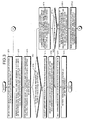
- Fig. 3 is a flowchart for explaining a procedure in which the plug-and-play server shown in Fig. 2 sets a radio channel of a mobile radio base-station.
- Fig. 3 depicts the process of setting a radio channel of the mobile radio base-station 24 at the time of installing the mobile radio base-station 24 in the coverage area 29 of the neighboring mobile radio base-station 25 and the coverage area 27 of the public radio base station 21 as shown in Fig. 2.
- the setting of a radio channel of the mobile radio base-station 25 at the time of installing the mobile radio base-station 25 in the state that only the public radio base station 21 is in operation is also carried out in a similar procedure. Therefore, in Fig. 3, it is assumed that radio channels are set to the public radio base station 21 and the mobile radio base-station 25 to avoid mutual interferences.
- the mobile radio base-station 24 searches adjacent cells for all frequencies that can be used in the radio communication system.
- the "all frequencies that can be used in the radio communication system” means frequencies that can be used in the mobile radio base-station and the public radio base station, respectively.
- the "cells” means logical radio terminal accommodation areas that are determined by the set of a part (sector) of the coverage area of the mobile radio base-station and the public radio base station partitioned by radio beam forming and frequencies used in this sector.
- the "search for cells” also includes carrier sense that is executed in the PHS (Personal Handy-phone System) and the like.
- Fig. 4 is a table for explaining cell configurations of the radio base stations shown in Fig. 2.
- cells of the public radio base station 21 and the mobile radio base-stations 24 and 25 are configured as shown in Fig. 4, and other cells also have similar configurations.
- the table contains such items as the number of sectors, the number of frequency multiplexes, the number of cells, the number of accommodated users/cell, and cell ID.
- the cell ID is an identification symbol or the like that can uniquely identify cells out of cells of all radio base stations in the radio communication system.
- Cell identity that is notified by a broadcast channel can be used.
- the mobile radio base-station 24 when having detected a cell of a power level that is not negligible in terms of interference as a result of cell search, the mobile radio base-station 24 records the ID of this cell. Assume that while cells corresponding to cell IDs "3131, 3133, and 3101" can be identified, cells corresponding to cell ID "3132" cannot be found in the "cell ID” column shown in Fig. 4. The mobile radio base-station 24 notifies, after confirming the connection to the HT 22, the PPS 20 of the IDs "3131, 3133, and 3101", which have been specified and recorded, via the Internet.
- the mobile radio base-station 24 can determine that the cell ID "3131” and the cell ID "3133” indicates the cells covered by the same base station, the mobile radio base-station 24 can report one of the cell IDs "3131” and "3133", and the cell ID "3101".
- the PPS 20 specifies the public radio base station 21 and the mobile radio base-station 25 based on the notified cell IDs, and inquires and acquires the radio-channel setting state of these cells.
- Fig. 5 a table for explaining radio-channel setting state in cells of the radio base stations detected by the mobile radio base-station for which a radio channel is to be set.
- the public radio base station 21 and the mobile radio base-station 25 notify the PPS 20 about the number of used frequencies, the number of unused frequencies, used codes, and reference transmission power, as shown in Fig. 5, for example.
- the frequency used by the mobile radio base-station 25 is F1
- that used or reserved code numbers are Cal and Ca2
- that transmission power of the reference channel for example, a common pilot channel (CPICH) of the W-CDMA
- CPICH common pilot channel
- the PPS 20 determines a frequency, a code, and transmission power of a radio channel used in the mobile radio base-station 24, from the frequencies, used codes, and transmission power of the returned cells, in the order of step ST4 to ST12.
- the PPS 20 does not use the frequency (F1) that is used by the mobile radio base-station 25 and the public radio base station, and searches an available frequency to be used by the mobile radio base-station 24 from the frequencies (F1 and F5) use of which is reserved for the mobile radio base-station.
- the PPS 20 selects an arbitrary frequency from the available frequencies (step ST5).
- the frequency F5 can be freely used, and the frequency F5 can be assigned to the mobile radio base-station 24. In this operation, orthogonality with other cell can be maintained in this frequency. Therefore, two codes as the maximum number of accommodated users that can be used in the mobile radio base-station 24 can be selected at random (step ST6).
- the PPS 20 sets transmission power of the mobile radio base-station 24 (step ST7), and notifies the mobile radio base-station 24 about a result of the setting via the Internet (step ST8).
- the PPS 20 can instruct the mobile radio base-station 24 about the selection of a code.
- the PPS 20 can instruct the mobile radio base-station 24 to select a code at random, and the mobile radio base-station 24 can select a code.
- step ST4 when no available frequency is found as a result of the search (step ST4: No), i.e., when the radio base stations 25 and 24 can use only the same frequency, the PPS 20 checks whether codes corresponding to the number of codes accommodated in the mobile radio base-station 24 can be selected out of codes that can be used in the mobile radio base-station 25 (step ST9).
- the PPS 20 checks whether codes corresponding to the number of accommodated users (the number of accommodated users is two, in this example) can be selected from codes not used by the mobile radio base-station 25.
- step ST10: Yes When the PPS 20 can select codes corresponding to the number of codes accommodated in the mobile radio base-station 24 (step ST10: Yes), the process proceeds to step ST7.
- step ST10: No When the number of usable codes is in short (step ST10: No), transmission power of the mobile radio base-station 25 is adjusted in relation to the neighboring mobile radio base-station (the mobile radio base-station 24, in the example of Fig. 2) in the method described later (Figs. 6 and 7), and the mobile radio base-station 24 is notified of abnormal end (step ST11). In this case, the mobile radio base-station 24 immediately or after a suitable interval restarts searching neighboring cells (step ST12), and performs process at step ST2. Because the transmission power of the neighboring mobile radio base-station (the mobile radio base-station 25, in the example of Fig. 2) is adjusted (step ST11), the mobile radio base-station 24 can be assigned a radio channel by retrial in many cases.
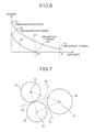
- Fig. 6 is a chart for explaining the power adjusting operation of the plug-and-play server shown in Fig. 2.
- Fig. 7 is a schematic for explaining a result of power adjustment.
- a relation between power in wave propagation and a propagation distance in a free space having no barriers, such as outdoor and indoor communications, can be modeled using a numerical expression. It is known that, in a free space, power is attenuated inversely proportional to a square of a propagation distance. When this relation is used, an approximate distance between a transmission-side mobile radio base-station and a receiving-side mobile radio base-station can be known from transmission power of a reference channel at the transmission-side mobile radio base-station and measured reception power of the reference channel in the receiving-side mobile radio base-station.
- the PPS 20 first issues a notification instruction to the neighboring mobile radio base-station (the mobile radio base-station 25, in this example) of the mobile radio base-station that requests for a channel setting, and obtains transmission power of the reference channel.
- the PPS 20 obtains an approximate distance between the neighboring two mobile radio base-stations, from the obtained transmission power of the reference channel and measured reception power that the mobile radio base-station (the mobile radio base-station 24, in this example) of the mobile radio base-station which requests for a channel setting notifies at the request time.
- the PPS 20 calculates transmission power P3 so that power is attenuated to a level equal to or lower than reception power P4 that is negligible in terms of interference, when the transmission-side mobile radio base-station 25 moves to a distance d/2 on the way to the mobile radio base-station 24.
- the PPS 20 controls the transmission power of the reference channel of the mobile radio base-station 25 so as not to exceed the value P3 from the relationship with the mobile radio base-station 24.
- a retry is performed.
- the mobile radio base-station 25 needs to readjust a relationship with another neighboring mobile radio base-station as a result of adjusting power in relation to the mobile radio base-station 24, the readjustment is performed in a similar procedure.
- Fig. 7 By performing the above power adjustment each time there is a request for a channel setting, overlapping of coverage areas of the mobile radio base-stations can be avoided, and interference can be avoided even if the same frequency and the same code are used as shown in Fig. 7.
- reference numerals 71 to 73 denote disposition positions of mobile radio base-stations
- reference numerals 74 to 76 denote perpendicular bisectors that connect between positions of two mobile radio base-stations.
- Reference numerals 77 to 79 denote coverage areas of mobile radio base-stations that are obtained as a result of power control.
- the coverage areas 77 to 79 shown in Fig. 7 are determined as follows.
- transmission power of the mobile radio base-station 71 and transmission power of the mobile radio base-station 73 are determined so that power is sufficiently attenuated in a distance equal to or smaller than a half of the line length between the mobile radio base-station 71 and the mobile radio base-station 73.
- the area 77 covered by the mobile radio base-station 71 and the area 79 covered by the mobile radio base-station 72 are both limited in size to the extent of the bisector 76.
- the area is limited in size to the extent defined by the bisector 74 between the mobile radio base-station 71 and the mobile radio base-station 72, and the area is limited in size to the extent defined by the bisector 75 between the mobile radio base-station 73 and the mobile radio base-station 72.
- transmission power needs to be controlled such that the coverage area 77 reaches the bisector 76.
- transmission power needs to be controlled such that the coverage area 77 reaches the bisector 74.
- the coverage area is adjusted to match a smaller one of the distance between the mobile radio base-station 71 and the bisector 74 and the distance between the mobile radio base-station 71 and the bisector 76.
- the coverage area 77 of the mobile radio base-station 71 has a range that touches the bisector 74 and does not touch the bisector 76.
- the coverage areas 78 and 79 of the mobile radio base-station 72 and the mobile radio base-station 73 are also obtained in a similar method. As shown in Fig. 7, the coverage area 78 of the mobile radio base-station 72 has a range that touches the bisector 74 and does not touch the bisector 75. The coverage area 79 of the mobile radio base-station 73 has a range that touches the bisector 75 and does not touch the bisector 76.
- the PPS 20 needs to periodically monitor the state of the mobile radio base-station, and set an optimal radio channel each time.
- the mobile radio base-station periodically, or during idling having no radio connection, executes the above operation sequence of the start up of the base station, thereby setting a radio channel; and (2) the PPS 20 holds a list of mobile radio base-stations that have requested a setting of a radio channel, and periodically checks whether the power to each of the mobile radio base-stations in the list is off, thereby updating a setting of a radio channel.
- a frequency used by the public radio base station is separated from a frequency used by a mobile radio base-station that is used indoors. Therefore, an optimal radio channel can be set to the mobile radio base-station, without changing the setting of the radio channel of the public radio base station. In other words, the mobile radio base-station can be selectively moved to an indoor convenient position.
- the mobile radio base-station uses a frequency that is not used by the public radio base station which is present around the mobile radio base-station. Therefore, a specific frequency band does not need to be reserved for a mobile radio base-station that is locally used in a short term, and high frequency-utilization efficiency can be maintained.
- the mobile radio base-station that is to be assigned a radio channel monitors a transmission radio channel of a neighboring radio base station, and notifies the PPS.
- the PPS inquires the notified neighboring radio base station about a setting state of a radio channel. Therefore, the PPS does not need to understand the disposition relationship of a radio base station, and can set an optimal radio channel to match the mobile radio base-station.
- the mobile radio base-station can be periodically monitored, and an optimal radio channel can be set each time. Therefore, the power of the mobile radio base-station can be freely turned off, and the mobile radio base-station can be moved with the power kept on.
- Fig. 8 is a conceptual diagram of a radio channel setting system for explaining a method of setting a radio channel of a mobile radio base-station according to a second embodiment of the present invention.
- constituent elements identical or equivalent to those shown in Fig. 2 (first embodiment) are designated by like reference numerals. Parts relevant to the second embodiment are mainly explained below.
- the radio channel setting system includes mobile radio base-stations 81 and 82 in place of the mobile radio base-stations 24 and 25 in the configuration shown in Fig. 2 (first embodiment).
- the mobile radio base-stations 81 and 82 include a GPS receiving function of receiving a GPS wave by a global positioning system (GPS) and obtaining a current position (GPS position information) of the own base station, in addition to the functions of the mobile radio base-stations 24 and 25.
- GPS global positioning system
- a circle 85 is a maximum reach range of a radio channel transmitted by the public radio base station 21.
- Circles 86 and 87 are maximum reach ranges of radio channels transmitted by the mobile radio base-stations 81 and 82. These maximum reach ranges of the radio channels are equal to a maximum cell radius of the radio base station, and are known information.
- a maximum cell radius of the mobile radio base-stations 81 and 82, i.e., the radius of the circles 86 and 87 is Rm, respectively.
- a maximum cell radius of the public radio base station 21, i.e., the radius of the circle 85 is Rp.
- a radio base station positioned near the mobile radio base-station that is assigned a radio channel is specified by GPS information.
- an explanation is made of the operation when the mobile radio base-station 81 is started up anew in the state that the mobile radio base-station 82 and the public radio base station 21 are operated without mutual interference.
- the mobile radio base-station 81 calculates a current position (GPS position information) of the own base station by using the incorporated GPS receiver, and notifies the PPS 20 about this current position.
- the PPS 20 has already obtained position information of other radio base stations (the public radio base station and the mobile radio base-station). In other words, the GPS position information of the mobile radio base-station in operation is already obtained at the channel-setting time. Therefore, the PPS 20 searches a radio base station of which circle using a maximum cell radius as a radius around the position of the radio base station is overlapped with the circle 86 of the radius Rm around the current position of the mobile radio base-station 81. When such a radio current base station is found, a setting state of a radio channel can be inquired to this radio base station.
- the circle 87 of the radius Rm around the position of the mobile radio base-station 82 and the circle 85 of the radius Rp around the position of the public radio base station 21 are overlapped with the circle 86 of the radius Rm around the position of the mobile radio base-station 81.
- the PPS 20 inquires the public radio base station 21 and the mobile radio base-station 82 about their setting states of radio channels.
- the mobile radio base-station 82 transmits the information shown in Fig. 4. Thereafter, frequencies and scrambling codes are assigned in the process explained in the first embodiment.
- the PPS 20 does not need to calculate a distance between mobile radio base-stations based on a difference between a transmission power value of the reference channel and a reception power value, and can directly calculate a distance from the GPS information notified from each mobile radio base-station.
- a neighboring mobile radio base-station can be searched in high precision using GPS position information at the start up time of the mobile radio base-station, thereby setting an optimal radio channel.
- Fig. 9 is a conceptual diagram of a radio channel setting system for explaining a method of setting a radio channel of a mobile radio base-station according to a third embodiment of the present invention.
- constituent elements identical or equivalent to those shown in Fig. 2 (first embodiment) are designated by like reference numerals. Parts relevant to the second embodiment are mainly explained below.
- the radio channel setting system includes a radio terminal 90 in place of the radio terminal 26 in the configuration shown in Fig. 2 (first embodiment). Further, mobile radio base-stations 91 and 92 are provided in place of the mobile radio base-stations 24 and 25.
- the radio terminal 90 and the mobile radio base-stations 91 and 92 include means that uses a radio communication system other than a radio communication system that is originally used, for example, a short-range communication unit such as infrared communication (IrDA) and Bluetooth.
- a radio communication system other than a radio communication system that is originally used, for example, a short-range communication unit such as infrared communication (IrDA) and Bluetooth.
- IrDA infrared communication
- Bluetooth Bluetooth
- the radio terminal 90 uses the originally-provided cell search function as a function of monitoring adjacent radio base stations (the public radio base station and the mobile radio base-stations).
- the mobile radio base-stations 91 and 92 display a signal indicating that the mobile radio base-stations 91 and 92 are waiting for a neighboring radio base station at the start up time, in a display unit (such as an LED and a liquid-crystal display panel).
- the radio terminal 90 When the radio terminal 90 has a GPS receiving function, the radio terminal 90 obtains a current position (GPS information) of the own terminal using the GPS receiving function, instead of monitoring an adjacent radio base station by the cell search.
- the mobile radio base-stations 91 and 92 can display a signal indicating that the mobile radio base-stations 91 and 92 are waiting for position information of the own radio base station, in a display unit (such as an LED and a liquid-crystal display panel), instead of the above display.
- the mobile radio base-station 91 waits, by displaying in the display unit a signal indicating that the mobile radio base-station 91 is waiting for information of a neighboring radio base station. Because the radio terminal is always searching cells, a cell ID of the radio base station can be obtained.
- the user of the radio terminal 90 belonging to the mobile radio base-station 91 confirms the signal indicating that the mobile radio base-station 91 is waiting for information of a neighboring radio base station displayed by the mobile radio base-station 91
- the user transfers the cell ID of the searched radio base station to the mobile radio base-station 91 by using a short-range communication unit.
- the cell IDs "3101, 3131, and 3133" are transferred to the mobile radio base-station 24 as in the first embodiment.
- the third embodiment when a user of the radio terminal 90 belonging to the mobile radio base-station 91 has a GPS receiving device, the user can calculate GPS position information in place of a result of the cell search, and can notify the mobile radio base-station 91 about the GPS position using a short-range communication unit, upon confirming a signal indicating a waiting for information of a neighboring radio base station or a signal indicating a waiting for position information of the own radio base station.
- the mobile radio base-station 91 transfers a cell ID of a neighboring radio base station received from the radio terminal 90 belonging to the mobile radio base-station 91, or GPS position information of the radio terminal 90 belonging to the mobile radio base-station 91, to the PPS 20.
- the PPS 20 specifies the radio base stations 92 and 21 that are present near the mobile radio base-station 91, based on the cell ID of the radio base station or the GPS position information of the radio terminal 90, in the process similar to that of the first embodiment.
- the PPS 20 inquires these radio base stations about setting states of radio channels, and determines a radio channel of the mobile radio base-station 91.
- cell search information that a radio terminal usually searches is used as information of a radio base station near the mobile radio base-station. Therefore, the mobile radio base-station does not need to have the cell search function, and the mobile radio base-station can be made compact.
- a position of the own radio terminal is calculated by using the GPS receiving function held by the radio terminal, and this position is notified to the mobile radio base-station. Therefore, the mobile radio base-station does not need to have the GPS receiving function, and the mobile radio base-station can be made compact.
- the method of setting a radio channel of a mobile radio base-station is useful in using a base station while changing the location of the base station to a desired position in a radio communication system established in a limited area or indoors.
Landscapes
- Engineering & Computer Science (AREA)
- Computer Networks & Wireless Communication (AREA)
- Signal Processing (AREA)
- Mobile Radio Communication Systems (AREA)
Abstract
To achieve a method of setting a radio channel of a mobile radio base-station that can be moved to an arbitrary position and used there to provide local and short-term services at home and within a specific object facility.
A mobile radio base-station includes an IP communication interface in addition to a radio resource control function, and can be moved. A plug-and-play server that manages a public radio base station for a mobile telephone network and a mobile radio base-station is located on an operator network that is connected to an IP communication network. The mobile radio base-station receives power on or reset operation, and notifies the plug-and-play server about position information of neighboring radio base stations. The plug-and-play server inquires a neighboring radio base station specified based on the notified position information about a setting state of radio channels, and obtains the setting state. The plug-and-play server then sets a radio channel of the mobile radio base-station by which the position information is notified, based on a setting state of a radio channel of a neighboring mobile radio base-station out of the obtained setting state of radio channels.
A mobile radio base-station includes an IP communication interface in addition to a radio resource control function, and can be moved. A plug-and-play server that manages a public radio base station for a mobile telephone network and a mobile radio base-station is located on an operator network that is connected to an IP communication network. The mobile radio base-station receives power on or reset operation, and notifies the plug-and-play server about position information of neighboring radio base stations. The plug-and-play server inquires a neighboring radio base station specified based on the notified position information about a setting state of radio channels, and obtains the setting state. The plug-and-play server then sets a radio channel of the mobile radio base-station by which the position information is notified, based on a setting state of a radio channel of a neighboring mobile radio base-station out of the obtained setting state of radio channels.
Description
- The present invention relates to a method of setting a radio channel of a mobile radio base-station that is movable and used in a radio communication system established in a limited area or indoors.
- An indoor radio communication system employs a configuration in which a radio-wave reaching distance is limited from about a few meters to a few tens of meters by limiting transmission power and radio base stations are arranged in the entire indoor service area at intervals of a few meters and a few tens of meters to use assigned radio frequency resources effectively to the maximum extent possible. In this case, radio channels need to be set to avoid mutual interference between frequencies of channels of the radio base stations.
- The method of assigning radio channels to radio base stations is broadly classified into two types. One is fixedly setting a frequency of a radio channel considering an assignment of radio channels to neighboring radio base stations and radio wave propagation at the time of establishing a radio base station (hereinafter, "fixed radio-channel setting"). The other is equally assigning a set of available frequencies to base stations in advance, and determining a frequency to be used in each radio base station at the time of activating the radio base station, at regular intervals, or at the time of communicating with a radio terminal to set a radio channel (hereinafter, "dynamic radio-channel setting").
- According to the fixed radio-channel setting, an assigned frequency, transmission power, etc. are fixedly used. Therefore, the operation of radio base stations and the radio channel selection control during communication are facilitated. On the other hand, it is difficult to assign radio channels to radio base stations located every few meters to every tens of meters in such a manner as to avoid mutual interference. In addition, radio wave propagation characteristics change easily due to layout modification in an indoor environment, and communication becomes impossible depending on circumstances.
- As explained above, because the fixed radio-channel setting cannot readily handle interference between radio channels of the same frequency, the dynamic radio-channel setting is preferable for the indoor radio communication system. A method of performing carrier sense each time radio communication is carried out to find an available frequency, and using this frequency is known as the dynamic radio-channel setting. This method is applied to a cordless telephone. However, because carrier sense needs to be performed each time radio communication is carried out, the control becomes complicated, and a delay occurs.
- A method of autonomously setting a radio channel of a radio base station by collecting and acquiring information on radio channels used by neighboring radio base stations has been proposed as a radio-channel allocation method that is a hybrid method of the fixed radio-channel setting and the dynamic radio-channel setting (for example,
Patent Documents 1 and 2). - For example, the
Patent Document 1 discloses a technology in which radio channel information is exchanged between neighboring radio base stations, and each radio base station autonomously sets a radio channel based on the obtained radio channel information at the time the radio base station is established. ThePatent Document 2 discloses a technology in which a management device is provided to consolidate the management of use state of radio channels of respective radio base stations to assign a radio channel to each radio base station. -
- Patent Document 1:
Japanese Patent Application Laid-open No. H6-334597 - Patent Document 2:
Japanese Patent Application Laid-open No. H8-9447 - To install a personal radio base station at home to provide extension telephone or hotspot data communication service, for example, a radio channel needs to be set up not to interfere with a public radio base station and a personal radio base station used in adjacent areas. It is desirable that a personal radio base station be a mobile radio base-station location of which can be changed freely according to the layout of the house or position of the user. Therefore, a personal radio base station needs to be capable of autonomously or automatically setting a radio channel.
- However, the conventional method of setting a radio channel of an indoor radio base station is based on the assumption that service provider installs many radio base stations having the same capacity and the same scale indoors to provide an indoor radio service. Therefore, it is difficult to change the location of a radio base station and install a personal radio base station without changing, for example, the setting of a radio channel of a public radio base station.
- The present invention has been achieved in view of the above problems, and it is an object of the present invention to provide a method of setting a radio channel of a mobile radio base-station that is used while arbitrarily changing its location to provide a local and short-term service at home or in a specific target facility.
- To achieve the object mentioned above, according to the present invention, a method of setting a radio channel of a mobile radio base-station that is applied to a radio communication system established in a limited area or indoors, the radio communication system including the mobile radio base-station that is movably installed, and includes an IP communication interface to access an IP communication network in addition to a radio resource control function, and a plug-and-play server that manages a public radio base station of a mobile telephone network and the mobile radio base-station and is located on an operator network connected to the IP communication network, includes a first step at which the mobile radio base-station, in which power is turned on or reset operation is performed, notifies the plug-and-play server about position information of a neighboring radio base station, and a second step at which the plug-and-play server inquires the neighboring radio base station specified based on the position information about radio-channel setting state to acquire the radio-channel setting state, and sets a radio channel of the mobile radio base-station that has notified the plug-and-play server of the position information by any one of frequency assignment and code assignment based on radio-channel setting state of a mobile radio base-station out of obtained radio-channel setting state of the neighboring radio base station.
- According to the present invention, a plug-and-play server can set an optimal radio channel depending on the location of a mobile radio base-station without acquiring a positional relationship between mobile radio base-stations.
- According to the present invention, it is possible to properly set a radio channel of a mobile radio base-station that is used while arbitrarily changing its location to provide a local and short-term service at home or in a specific target facility.
-
- [Fig. 1] Fig. 1 is a conceptual diagram of an example of an entire configuration of a setting system to which is applied a method of setting a radio channel of a mobile radio base-station according to the present invention.
- [Fig. 2] Fig. 2 is a conceptual diagram of a radio channel setting system for explaining a method of setting a radio channel of a mobile radio base-station according to a first embodiment of the present invention.
- [Fig. 3] Fig. 3 is a flowchart for explaining a procedure in which a plug-and-play server shown in Fig. 2 sets a radio channel of a mobile radio base-station.
- [Fig. 4] Fig. 4 is a table for explaining cell configurations of radio base stations shown in Fig. 2.
- [Fig. 5] Fig. 5 a table for explaining radio-channel setting state in cells of radio base stations detected by the mobile radio base-station for which a radio channel is to be set.
- [Fig. 6] Fig. 6 is a chart for explaining a power adjusting operation of the plug-and-play server shown in Fig. 2.
- [Fig. 7] Fig. 7 is a schematic for explaining a result of power adjustment.
- [Fig. 8] Fig. 8 is a conceptual diagram of a radio channel setting system for explaining a method of setting a radio channel of a mobile radio base-station according to a second embodiment of the present invention.
- [Fig. 9] Fig. 9 is a conceptual diagram of a radio channel setting system for explaining a method of setting a radio channel of a mobile radio base-station according to a third embodiment of the present invention.
-
- 1a, 1b, 1c Limited area such as floors within building or venues in exhibition hall
- 2a, 2b, 2c, 22, 23 Home terminal (HT)
- 3a, 3b, 3c, 24, 25, 81, 82 Mobile radio base-station (BTS)
- 4a, 4b, 4c, 26, 90 Radio terminal (UE)
- 10, 11 ISP network
- 12 Internet
- 13 Operator network
- 14, 20 Plug-and-play server (PPS)
- 21 Public radio base station
- 27, 28, 29 Coverage area
- 71, 72, 73 Location of mobile radio base-station
- 74, 75, 76 Bisector between locations of mobile radio base-stations
- 77, 78, 79 Transmission-power adjustment area
- 85, 86, 87 Maximum reach range
- Exemplary embodiments of a method of setting a radio channel of a mobile radio base-station according to the present invention are explained below in detail with reference to the accompanying drawings.
- Fig. 1 is a conceptual diagram of an example of an entire configuration of a setting system to which is applied a method of setting a radio channel of a mobile radio base-station according to the present invention. In Fig. 1,
limited areas limited areas limited areas - The
home terminals limited areas - In Fig. 1, two
ISP networks home terminals ISP network 10, and thehome terminal 2c is connected to theISP network 11. - The mobile radio base-
stations limited areas stations home terminals Internet 12 using the IP (Internet Protocol). - The mobile radio base-
stations - The ISP networks 10 and 11 are connected to an
operator network 13 that is managed by a communications carrier. In other words, the ISP networks 10 and 11 and theoperator network 13 are connected to each other by the IP on theInternet 12. - According to the present invention, a plug-and-play server (PPS) 14 is located in the
operator network 13. The plug-and-play server 14 is a server that operates and manages the mobile radio base-stations play server 14 includes functions of setting radio channels of the mobile radio base-stations stations limited areas - A method of setting a radio channel of a mobile radio base-station according to the first embodiment is explained below with reference to Figs. 2 to 7. Fig. 2 is a conceptual diagram of a radio channel setting system for explaining the method of setting a radio channel of the mobile radio base-station according to the first embodiment of the present invention.
- Fig. 2 selectively depicts a configuration concerning the radio channel setting system out of the configuration shown in Fig. 1 using new reference numerals. In Fig. 2, a public
radio base station 21 and home terminals (hereinafter, "HT") 22 and 23 are connected to a plug-and-play server (hereinafter, "PPS") 20 via a network as shown in Fig. 1. A mobile radio base-station (BTS) 24 is connected by wire or wireless to theHT 22. A mobile radio base-station (BTS) 25 is connected by wire or wireless to theHT 23.Reference numerals radio base station 21 and the mobile radio base-stations - In the outdoor radio cellular communication system and the outdoor cordless telephone system, transmission power and installation positions of radio base stations are adjusted to overlap the coverage areas of the adjacent radio base stations to enable users to continue communications when the users move. However, one of the objects of the present invention is to provide a radio communication service as a hot spot to only users who are present in a limited space such as a home, a shop, and an exhibition hall. Therefore, ideally, overlapping of a coverage area of a public radio base station installed outdoors and a coverage area of a mobile radio base-station installed in a limited area such as indoors should be avoided.
- However, some public radio base stations cover an area of a few hundred meters to a few tens of kilometers, and their waves often reach indoors. When a mobile radio base-station installed in each home of a condominium or residential areas is present nearby, there is a possibility that the coverage areas of the mobile radio base-stations overlap each other.
- Fig. 2 depicts a state that, as a worst case, the mobile radio base-
station 24 is installed within a range in which thecoverage area 29 of the neighboring mobile radio base-station 25 and thecoverage area 27 of the publicradio base station 21 are redundantly present, in the state that thecoverage area 29 of the mobile radio base-station 25 is partly redundant with thecoverage area 27 of the publicradio base station 21. Aradio terminal 26 is shown within thecoverage area 28 of the mobile radio base-station 24. - In the setting of a radio channel of the mobile radio base-station according to the present invention, giving interference to the public radio base station by the dynamic setting of a radio channel or forcing a change in the setting of a radio channel of the public radio base station should be avoided. This is because the convenience of the public cannot be decreased by the convenience of individual. Therefore, in the present invention, to separate the setting of a radio channel of the public radio base station from the setting of a radio channel of the mobile radio base-station for individuals, the frequency used by the public
radio base station 21 is made different from the frequencies used by the mobile radio base-stations PPS 20 manages so that the frequencies used by the mobile radio base-stations are different from the frequency used by the neighboring public radio base station. - In this case, when a low frequency is assigned to a mobile radio base-station in the frequency band that can be used by the radio communication system, resistance to a layout change indoors can be improved by a wraparound effect of waves. However, when a frequency is reserved for the mobile radio base-station that is locally used during a short term, frequencies that can be used by the public radio base station decrease, and the frequency utilization efficiency decreases. Therefore, in the present invention, a frequency that cannot be used by a public radio base station is defined in each area in which the public radio base station is installed, and this frequency is assigned to a mobile radio base-station. In other words, a frequency that a mobile radio base-station can use is different for each area.
- Fig. 3 is a flowchart for explaining a procedure in which the plug-and-play server shown in Fig. 2 sets a radio channel of a mobile radio base-station. Fig. 3 depicts the process of setting a radio channel of the mobile radio base-
station 24 at the time of installing the mobile radio base-station 24 in thecoverage area 29 of the neighboring mobile radio base-station 25 and thecoverage area 27 of the publicradio base station 21 as shown in Fig. 2. The setting of a radio channel of the mobile radio base-station 25 at the time of installing the mobile radio base-station 25 in the state that only the publicradio base station 21 is in operation is also carried out in a similar procedure. Therefore, in Fig. 3, it is assumed that radio channels are set to the publicradio base station 21 and the mobile radio base-station 25 to avoid mutual interferences. - In Fig. 3, at step ST1, when the power is turned on or reset operation is performed, the mobile radio base-
station 24 searches adjacent cells for all frequencies that can be used in the radio communication system. The "all frequencies that can be used in the radio communication system" means frequencies that can be used in the mobile radio base-station and the public radio base station, respectively. The "cells" means logical radio terminal accommodation areas that are determined by the set of a part (sector) of the coverage area of the mobile radio base-station and the public radio base station partitioned by radio beam forming and frequencies used in this sector. For example, when the coverage area of a certain radio base station in the mobile radio base-station and the public radio base station is divided by each 60° into six sectors, and when four frequencies are used in each sector, one radio base station manages 6×4=24 cells. Therefore, in this embodiment, while the CDMA system is explained as an example, the "search for cells" also includes carrier sense that is executed in the PHS (Personal Handy-phone System) and the like. - Fig. 4 is a table for explaining cell configurations of the radio base stations shown in Fig. 2. In the embodiment, to simplify the explanation, cells of the public
radio base station 21 and the mobile radio base-stations - At the next step ST2, when having detected a cell of a power level that is not negligible in terms of interference as a result of cell search, the mobile radio base-
station 24 records the ID of this cell. Assume that while cells corresponding to cell IDs "3131, 3133, and 3101" can be identified, cells corresponding to cell ID "3132" cannot be found in the "cell ID" column shown in Fig. 4. The mobile radio base-station 24 notifies, after confirming the connection to theHT 22, thePPS 20 of the IDs "3131, 3133, and 3101", which have been specified and recorded, via the Internet. When the mobile radio base-station 24 can determine that the cell ID "3131" and the cell ID "3133" indicates the cells covered by the same base station, the mobile radio base-station 24 can report one of the cell IDs "3131" and "3133", and the cell ID "3101". - At step ST3, the
PPS 20 specifies the publicradio base station 21 and the mobile radio base-station 25 based on the notified cell IDs, and inquires and acquires the radio-channel setting state of these cells. Fig. 5 a table for explaining radio-channel setting state in cells of the radio base stations detected by the mobile radio base-station for which a radio channel is to be set. In response to the inquiry from thePPS 20, the publicradio base station 21 and the mobile radio base-station 25 notify thePPS 20 about the number of used frequencies, the number of unused frequencies, used codes, and reference transmission power, as shown in Fig. 5, for example. - It is clear from the content of notification (Fig. 5) that the frequency used by the mobile radio base-
station 25 is F1, that used or reserved code numbers are Cal and Ca2, that transmission power of the reference channel (for example, a common pilot channel (CPICH) of the W-CDMA) is Pa, and that frequencies F1 and F5 are reserved for the mobile radio base-station around the publicradio base station 21. - The
PPS 20 determines a frequency, a code, and transmission power of a radio channel used in the mobile radio base-station 24, from the frequencies, used codes, and transmission power of the returned cells, in the order of step ST4 to ST12. - In other words, at step ST4, the
PPS 20 does not use the frequency (F1) that is used by the mobile radio base-station 25 and the public radio base station, and searches an available frequency to be used by the mobile radio base-station 24 from the frequencies (F1 and F5) use of which is reserved for the mobile radio base-station. - When available frequencies are found as a result of the search (step ST4: Yes), the
PPS 20 selects an arbitrary frequency from the available frequencies (step ST5). When a response as shown in Fig. 5 is obtained, the frequency F5 can be freely used, and the frequency F5 can be assigned to the mobile radio base-station 24. In this operation, orthogonality with other cell can be maintained in this frequency. Therefore, two codes as the maximum number of accommodated users that can be used in the mobile radio base-station 24 can be selected at random (step ST6). ThePPS 20 sets transmission power of the mobile radio base-station 24 (step ST7), and notifies the mobile radio base-station 24 about a result of the setting via the Internet (step ST8). ThePPS 20 can instruct the mobile radio base-station 24 about the selection of a code. Alternatively, thePPS 20 can instruct the mobile radio base-station 24 to select a code at random, and the mobile radio base-station 24 can select a code. - On the other hand, when no available frequency is found as a result of the search (step ST4: No), i.e., when the
radio base stations PPS 20 checks whether codes corresponding to the number of codes accommodated in the mobile radio base-station 24 can be selected out of codes that can be used in the mobile radio base-station 25 (step ST9). - In the example of Fig. 5, when the frequency F5 is used in the public radio base station and cannot be used in the mobile radio base-station, i.e., when the mobile radio base-
stations PPS 20 checks whether codes corresponding to the number of accommodated users (the number of accommodated users is two, in this example) can be selected from codes not used by the mobile radio base-station 25. - When the
PPS 20 can select codes corresponding to the number of codes accommodated in the mobile radio base-station 24 (step ST10: Yes), the process proceeds to step ST7. When the number of usable codes is in short (step ST10: No), transmission power of the mobile radio base-station 25 is adjusted in relation to the neighboring mobile radio base-station (the mobile radio base-station 24, in the example of Fig. 2) in the method described later (Figs. 6 and 7), and the mobile radio base-station 24 is notified of abnormal end (step ST11). In this case, the mobile radio base-station 24 immediately or after a suitable interval restarts searching neighboring cells (step ST12), and performs process at step ST2. Because the transmission power of the neighboring mobile radio base-station (the mobile radio base-station 25, in the example of Fig. 2) is adjusted (step ST11), the mobile radio base-station 24 can be assigned a radio channel by retrial in many cases. - In other words, when the mobile radio stations use the same frequency and also use the same code, the transmission power of the mobile radio base-stations are adjusted to narrow the coverage areas of the respective mobile radio base-station. This can sometimes avoid causing mutual interference even if the same frequency and the same code are used. Specifically, transmission power of the mobile radio base-stations is adjusted to be approximately at the same level between neighboring two mobile radio base-stations. A power adjusting method is explained below with reference to Figs. 6 and 7. Fig. 6 is a chart for explaining the power adjusting operation of the plug-and-play server shown in Fig. 2. Fig. 7 is a schematic for explaining a result of power adjustment.
- A relation between power in wave propagation and a propagation distance in a free space having no barriers, such as outdoor and indoor communications, can be modeled using a numerical expression. It is known that, in a free space, power is attenuated inversely proportional to a square of a propagation distance. When this relation is used, an approximate distance between a transmission-side mobile radio base-station and a receiving-side mobile radio base-station can be known from transmission power of a reference channel at the transmission-side mobile radio base-station and measured reception power of the reference channel in the receiving-side mobile radio base-station.
- The
PPS 20 first issues a notification instruction to the neighboring mobile radio base-station (the mobile radio base-station 25, in this example) of the mobile radio base-station that requests for a channel setting, and obtains transmission power of the reference channel. ThePPS 20 obtains an approximate distance between the neighboring two mobile radio base-stations, from the obtained transmission power of the reference channel and measured reception power that the mobile radio base-station (the mobile radio base-station 24, in this example) of the mobile radio base-station which requests for a channel setting notifies at the request time. In Fig. 6, when the transmission power of the reference channel of the transmission-side mobile radio base-station is P1 and also when the reception power of the reference channel of the reception-side mobile radio base-station is P2, an attenuation characteristic is obtained as shown by acurve 61, by modeling the relationship between the wave propagation distance and the power attenuation. Therefore, a distance between the both mobile radio base-stations can be known as approximately d. - Next, the
PPS 20 calculates transmission power P3 so that power is attenuated to a level equal to or lower than reception power P4 that is negligible in terms of interference, when the transmission-side mobile radio base-station 25 moves to a distance d/2 on the way to the mobile radio base-station 24. ThePPS 20 controls the transmission power of the reference channel of the mobile radio base-station 25 so as not to exceed the value P3 from the relationship with the mobile radio base-station 24. In this case, because the mobile radio base-station 24 that requests for a channel setting also has a relationship with other neighboring mobile radio base-station, a retry is performed. When the mobile radio base-station 25 needs to readjust a relationship with another neighboring mobile radio base-station as a result of adjusting power in relation to the mobile radio base-station 24, the readjustment is performed in a similar procedure. - By performing the above power adjustment each time there is a request for a channel setting, overlapping of coverage areas of the mobile radio base-stations can be avoided, and interference can be avoided even if the same frequency and the same code are used as shown in Fig. 7.
In Fig. 7,reference numerals 71 to 73 denote disposition positions of mobile radio base-stations, andreference numerals 74 to 76 denote perpendicular bisectors that connect between positions of two mobile radio base-stations.Reference numerals 77 to 79 denote coverage areas of mobile radio base-stations that are obtained as a result of power control. Thecoverage areas 77 to 79 shown in Fig. 7 are determined as follows. - For example, when only the mobile radio base-
station 71 and the mobile radio base-station 73 are present, transmission power of the mobile radio base-station 71 and transmission power of the mobile radio base-station 73 are determined so that power is sufficiently attenuated in a distance equal to or smaller than a half of the line length between the mobile radio base-station 71 and the mobile radio base-station 73. As a result, thearea 77 covered by the mobile radio base-station 71 and thearea 79 covered by the mobile radio base-station 72 are both limited in size to the extent of thebisector 76. - When the mobile radio base-
station 72 is added in this situation, the area is limited in size to the extent defined by thebisector 74 between the mobile radio base-station 71 and the mobile radio base-station 72, and the area is limited in size to the extent defined by thebisector 75 between the mobile radio base-station 73 and the mobile radio base-station 72. When attention is focused on the mobile radio base-station 71, to avoid causing interference to the mobile radio base-station 73, transmission power needs to be controlled such that thecoverage area 77 reaches thebisector 76. On the other hand, to avoid causing interference to the mobile radio base-station 72, transmission power needs to be controlled such that thecoverage area 77 reaches thebisector 74. - In the transmission power control of the mobile radio base-
station 71, to avoid causing interference to both the mobile radio base-station 72 and the mobile radio base-station 73, the coverage area is adjusted to match a smaller one of the distance between the mobile radio base-station 71 and the bisector 74 and the distance between the mobile radio base-station 71 and thebisector 76. As a result, thecoverage area 77 of the mobile radio base-station 71 has a range that touches thebisector 74 and does not touch thebisector 76. - The
coverage areas station 72 and the mobile radio base-station 73 are also obtained in a similar method. As shown in Fig. 7, thecoverage area 78 of the mobile radio base-station 72 has a range that touches thebisector 74 and does not touch thebisector 75. Thecoverage area 79 of the mobile radio base-station 73 has a range that touches thebisector 75 and does not touch thebisector 76. - The above is the explanation of the operation performed when the mobile radio base-
station 24 is started up anew, i.e., when the power is turned on or when reset operation is performed. Because the mobile radio base-station can be installed by an individual at home, there is a possibility that the power is turned off after the mobile radio base-station is started, or the mobile radio base-station is moved with the power kept on. Therefore, thePPS 20 needs to periodically monitor the state of the mobile radio base-station, and set an optimal radio channel each time. - For this purpose, the following two methods can be used: (1) the mobile radio base-station periodically, or during idling having no radio connection, executes the above operation sequence of the start up of the base station, thereby setting a radio channel; and (2) the
PPS 20 holds a list of mobile radio base-stations that have requested a setting of a radio channel, and periodically checks whether the power to each of the mobile radio base-stations in the list is off, thereby updating a setting of a radio channel. - As explained above, according to the first embodiment, a frequency used by the public radio base station is separated from a frequency used by a mobile radio base-station that is used indoors. Therefore, an optimal radio channel can be set to the mobile radio base-station, without changing the setting of the radio channel of the public radio base station. In other words, the mobile radio base-station can be selectively moved to an indoor convenient position.
- The mobile radio base-station uses a frequency that is not used by the public radio base station which is present around the mobile radio base-station. Therefore, a specific frequency band does not need to be reserved for a mobile radio base-station that is locally used in a short term, and high frequency-utilization efficiency can be maintained.
- The mobile radio base-station that is to be assigned a radio channel monitors a transmission radio channel of a neighboring radio base station, and notifies the PPS. The PPS inquires the notified neighboring radio base station about a setting state of a radio channel. Therefore, the PPS does not need to understand the disposition relationship of a radio base station, and can set an optimal radio channel to match the mobile radio base-station.
- In addition, after the mobile radio base-station is started up, the mobile radio base-station can be periodically monitored, and an optimal radio channel can be set each time. Therefore, the power of the mobile radio base-station can be freely turned off, and the mobile radio base-station can be moved with the power kept on.
- Fig. 8 is a conceptual diagram of a radio channel setting system for explaining a method of setting a radio channel of a mobile radio base-station according to a second embodiment of the present invention. In Fig. 8, constituent elements identical or equivalent to those shown in Fig. 2 (first embodiment) are designated by like reference numerals. Parts relevant to the second embodiment are mainly explained below.
- In Fig. 8, the radio channel setting system according to the second embodiment includes mobile radio base-
stations stations stations stations - In Fig. 8, a
circle 85 is a maximum reach range of a radio channel transmitted by the publicradio base station 21.Circles stations stations circles radio base station 21, i.e., the radius of thecircle 85 is Rp. - In short, in the second embodiment, a radio base station positioned near the mobile radio base-station that is assigned a radio channel is specified by GPS information. As in the first embodiment, an explanation is made of the operation when the mobile radio base-
station 81 is started up anew in the state that the mobile radio base-station 82 and the publicradio base station 21 are operated without mutual interference. - In Fig. 8, upon power being turning on or reset operation, the mobile radio base-
station 81 calculates a current position (GPS position information) of the own base station by using the incorporated GPS receiver, and notifies thePPS 20 about this current position. ThePPS 20 has already obtained position information of other radio base stations (the public radio base station and the mobile radio base-station). In other words, the GPS position information of the mobile radio base-station in operation is already obtained at the channel-setting time. Therefore, thePPS 20 searches a radio base station of which circle using a maximum cell radius as a radius around the position of the radio base station is overlapped with thecircle 86 of the radius Rm around the current position of the mobile radio base-station 81. When such a radio current base station is found, a setting state of a radio channel can be inquired to this radio base station. - In the example shown in Fig. 8, the
circle 87 of the radius Rm around the position of the mobile radio base-station 82 and thecircle 85 of the radius Rp around the position of the publicradio base station 21 are overlapped with thecircle 86 of the radius Rm around the position of the mobile radio base-station 81. - The
PPS 20 inquires the publicradio base station 21 and the mobile radio base-station 82 about their setting states of radio channels. The mobile radio base-station 82 transmits the information shown in Fig. 4. Thereafter, frequencies and scrambling codes are assigned in the process explained in the first embodiment. In this case, in the adjustment of transmission power, thePPS 20 does not need to calculate a distance between mobile radio base-stations based on a difference between a transmission power value of the reference channel and a reception power value, and can directly calculate a distance from the GPS information notified from each mobile radio base-station. - As explained above, according to the second embodiment, a neighboring mobile radio base-station can be searched in high precision using GPS position information at the start up time of the mobile radio base-station, thereby setting an optimal radio channel.
- Fig. 9 is a conceptual diagram of a radio channel setting system for explaining a method of setting a radio channel of a mobile radio base-station according to a third embodiment of the present invention. In Fig. 9, constituent elements identical or equivalent to those shown in Fig. 2 (first embodiment) are designated by like reference numerals. Parts relevant to the second embodiment are mainly explained below.
- In Fig. 9, the radio channel setting system according to the third embodiment includes a
radio terminal 90 in place of theradio terminal 26 in the configuration shown in Fig. 2 (first embodiment). Further, mobile radio base-stations stations - The
radio terminal 90 and the mobile radio base-stations - The
radio terminal 90 uses the originally-provided cell search function as a function of monitoring adjacent radio base stations (the public radio base station and the mobile radio base-stations). In this case, the mobile radio base-stations stations - When the
radio terminal 90 has a GPS receiving function, theradio terminal 90 obtains a current position (GPS information) of the own terminal using the GPS receiving function, instead of monitoring an adjacent radio base station by the cell search. In this case, at the start up time, the mobile radio base-stations stations - As in the first embodiment, an explanation is made of the operation when the mobile radio base-
station 91 is started up anew in the state that the mobile radio base-station 92 and the publicradio base station 21 are operated without mutual interference. - In Fig. 9, upon power being turning on or reset operation, the mobile radio base-
station 91 waits, by displaying in the display unit a signal indicating that the mobile radio base-station 91 is waiting for information of a neighboring radio base station. Because the radio terminal is always searching cells, a cell ID of the radio base station can be obtained. When a user of theradio terminal 90 belonging to the mobile radio base-station 91 confirms the signal indicating that the mobile radio base-station 91 is waiting for information of a neighboring radio base station displayed by the mobile radio base-station 91, the user transfers the cell ID of the searched radio base station to the mobile radio base-station 91 by using a short-range communication unit. In this example, it is assumed that the cell IDs "3101, 3131, and 3133" are transferred to the mobile radio base-station 24 as in the first embodiment. - Further, in recent years, many radio terminals installed with GPS receiving devices appear, and provision of services using position information of radio terminals is started. Therefore, in the third embodiment, when a user of the
radio terminal 90 belonging to the mobile radio base-station 91 has a GPS receiving device, the user can calculate GPS position information in place of a result of the cell search, and can notify the mobile radio base-station 91 about the GPS position using a short-range communication unit, upon confirming a signal indicating a waiting for information of a neighboring radio base station or a signal indicating a waiting for position information of the own radio base station. - The mobile radio base-
station 91 transfers a cell ID of a neighboring radio base station received from theradio terminal 90 belonging to the mobile radio base-station 91, or GPS position information of theradio terminal 90 belonging to the mobile radio base-station 91, to thePPS 20. - As a result, the
PPS 20 specifies theradio base stations station 91, based on the cell ID of the radio base station or the GPS position information of theradio terminal 90, in the process similar to that of the first embodiment. ThePPS 20 inquires these radio base stations about setting states of radio channels, and determines a radio channel of the mobile radio base-station 91. - As described above, according to the third embodiment, cell search information that a radio terminal usually searches is used as information of a radio base station near the mobile radio base-station. Therefore, the mobile radio base-station does not need to have the cell search function, and the mobile radio base-station can be made compact.
- A position of the own radio terminal is calculated by using the GPS receiving function held by the radio terminal, and this position is notified to the mobile radio base-station. Therefore, the mobile radio base-station does not need to have the GPS receiving function, and the mobile radio base-station can be made compact.
- As explained above, the method of setting a radio channel of a mobile radio base-station according to the present invention is useful in using a base station while changing the location of the base station to a desired position in a radio communication system established in a limited area or indoors.
Claims (13)
- A method of setting a radio channel of a mobile radio base-station that is applied to a radio communication system established in a limited area or indoors, the radio communication system including the mobile radio base-station that is movably installed, and includes an IP communication interface to access an IP communication network in addition to a radio resource control function, and a plug-and-play server that manages a public radio base station of a mobile telephone network and the mobile radio base-station and is located on an operator network connected to the IP communication network, the method comprising:a first step at which the mobile radio base-station, in which power is turned on or reset operation is performed, notifies the plug-and-play server about position information of a neighboring radio base station; anda second step at which the plug-and-play server inquires the neighboring radio base station specified based on the position information about radio-channel setting state to acquire the radio-channel setting state, and sets a radio channel of the mobile radio base-station that has notified the plug-and-play server of the position information by any one of frequency assignment and code assignment based on radio-channel setting state of a mobile radio base-station out of obtained radio-channel setting state of the neighboring radio base station.
- The method of setting a radio channel of a mobile radio base-station according to claim 1, comprising a third step at which the plug-and-play server updates a setting of a radio channel upon receiving a notification of position information of a neighboring radio base station from each mobile radio base-station in operation.
- The method of setting a radio channel of a mobile radio base-station according to claim 1, comprising a third step at which the plug-and-play server updates a setting of a radio channel, by inquiring each mobile radio base-station in operation about position information of a neighboring radio base station, and obtaining the position information.
- The method of setting a radio channel of a mobile radio base-station according to claim 1, wherein the first step includes a step at which a mobile radio base-station carries out a cell search when power is turned on or reset operation is carried out, and notifies the plug-and-play server about a cell ID of a found neighboring radio base station as the position information.
- The method of setting a radio channel of a mobile radio base-station according to claim 1, wherein the first step includes: a step at which a mobile radio base-station displays a signal indicating a waiting for information of neighboring radio base stations, when the power is turned on or reset operation is carried out; a step at which a radio terminal that moves within the radio communication system transmits a cell ID of a radio base station adjacent to the mobile radio base-station found by carrying out a cell search in the coverage area of the mobile radio base-station in which the radio terminal moving within the radio communication system is displaying the waiting, to the mobile radio base-station using a radio communication system according to a user operation other than a radio communication system used in communications with the mobile radio base-station; and a step at which the mobile radio base-station that displays the waiting notifies the plug-and-play server about the cell ID of the neighboring radio base station received from the radio terminal as the position information.
- The method of setting a radio channel of a mobile radio base-station according to claim 1, wherein at the second step, the plug-and-play server assigns a frequency not used by the peripheral public radio base station to the mobile radio base-station.
- The method of setting a radio channel of a mobile radio base-station according to claim 1, wherein the second step includes: a step at which the plug-and-play serer executes the first step again to a mobile radio base-station to which the position information is notified, when interference with the mobile radio base-station to which the position information is notified cannot be avoided by assigning a frequency or assigning a code; and a step at which the plug-and-play server makes an adjacent mobile radio base-station that a mobile radio base-station to which the position information is notified searches calculate a distance between two mobile radio base-stations by considering attenuation from a difference between transmission power obtained by requesting a notification of transmission power of a reference channel and measured reception power obtained from a mobile radio base-station to which the position information is notified, and adjust transmission power so that a cell radius of an arbitrary mobile radio base-station becomes equal to or smaller than a half of a distance to the adjacent mobile radio base-station.
- A method of setting a radio channel of a mobile radio base-station, comprising:a first step at which a mobile radio base-station to which power is turned on or reset operation is carried out notifies a plug-and-play server about position information of the own radio base station; anda second step at which the plug-and-play server inquires a neighboring radio base station specified based on the notified position information about a setting state of radio channels, thereby obtaining the setting states, and sets a radio channel of a mobile radio base-station to which the position information is notified, by assigning a frequency or assigning a code based on a setting state of a radio channel of a mobile radio base-station in the neighboring radio base station out of the obtained setting state of radio channels,in the mobile radio base-station that is movably installed, including an IP communication interface that communicates with an IP communication network in addition to a radio resource control function in a radio communication system built in a limited area or indoors, wherein the plug-and-play server that manages a public radio base station of a mobile telephone network and the mobile radio base-station on an operator network connected to the IP communication network.
- The method of setting a radio channel of a mobile radio base-station according to claim 8, comprising a third step at which the plug-and-play server updates a setting of a radio channel upon receiving a notification of position information of the own radio base station from each mobile radio base-station in operation.
- The method of setting a radio channel of a mobile radio base-station according to claim 8, comprising a third step at which the plug-and-play server updates a setting of a radio channel, by inquiring each mobile radio base-station in operation about position information of the own radio base station, and obtaining the position information.
- The method of setting a radio channel of a mobile radio base-station according to claim 8, wherein the first step includes a step at which a mobile radio base-station calculates a current position of the own radio base station using a GPS receiving function when power is turned on or reset operation is carried out, and notifies the plug-and-play server about the calculated current position of the own radio base station as the position information.
- The method of setting a radio channel of a mobile radio base-station according to claim 8, wherein the first step includes: a step at which a mobile radio base-station displays a signal indicating a waiting for information of the own radio base station, when power is turned on or reset operation is carried out; a step at which a radio terminal that moves within the radio communication system calculates a current position of the own radio terminal using a GPS receiving function in the coverage area of the mobile radio base-station in which the radio terminal moving within the radio communication system is displaying the waiting, and transmits the calculated current position of the own radio terminal to the mobile radio base-station using a radio communication system according to a user operation other than a radio communication system used in communications with the mobile radio base-station; and a step at which the mobile radio base-station that displays the waiting notifies the plug-and-play server about the current position of the radio terminal that the mobile radio base-station displaying the waiting receives from the radio terminal, as the position information.
- The method of setting a radio channel of a mobile radio base-station according to claim 8, wherein the second step includes: a step at which the plug-and-play serer executes the first step again to a mobile radio base-station to which the position information is notified, when interference with the mobile radio base-station to which the position information is notified cannot be avoided by assigning a frequency or assigning a code; and a step at which the plug-and-play server makes a mobile radio base-station other than a mobile radio base-station that notifies the position information calculate a distance between two mobile radio base-stations from position information using a GPS receiving function of the own radio base station obtained at the channel-setting time and position information obtained from a mobile radio base-station to which the position information is notified, and adjust transmission power so that a cell radius of an arbitrary mobile radio base-station becomes equal to or smaller than a half of a distance to the adjacent mobile radio base-station.
Applications Claiming Priority (1)
| Application Number | Priority Date | Filing Date | Title |
|---|---|---|---|
| PCT/JP2004/017142 WO2006054341A1 (en) | 2004-11-18 | 2004-11-18 | Mobile radio base station radio channel setting method |
Publications (2)
| Publication Number | Publication Date |
|---|---|
| EP1814343A1 true EP1814343A1 (en) | 2007-08-01 |
| EP1814343A4 EP1814343A4 (en) | 2009-12-16 |
Family
ID=36406889
Family Applications (1)
| Application Number | Title | Priority Date | Filing Date |
|---|---|---|---|
| EP04822630A Withdrawn EP1814343A4 (en) | 2004-11-18 | 2004-11-18 | RADIO CHANNEL ADJUSTMENT METHOD FOR MOBILE RADIO BASE STATION |
Country Status (5)
| Country | Link |
|---|---|
| US (1) | US20080070565A1 (en) |
| EP (1) | EP1814343A4 (en) |
| JP (1) | JP4358235B2 (en) |
| CN (1) | CN101053267A (en) |
| WO (1) | WO2006054341A1 (en) |
Cited By (5)
| Publication number | Priority date | Publication date | Assignee | Title |
|---|---|---|---|---|
| EP2141942A1 (en) * | 2008-07-01 | 2010-01-06 | Nokia Siemens Networks Oy | Autonomous configuration of communication network |
| CN102256281A (en) * | 2010-05-19 | 2011-11-23 | 鼎桥通信技术有限公司 | Method, system and device for confirming omitted adjacent cell in mobile communication system |
| CN101686460B (en) * | 2008-09-25 | 2013-06-05 | 中兴通讯股份有限公司 | Method for distributing connection identifiers |
| US8879406B2 (en) | 2007-05-28 | 2014-11-04 | Telefonaktiebolaget Lm Ericsson (Publ) | User equipment tracing in a wireless communications network |
| EP2315468A4 (en) * | 2008-08-08 | 2017-02-15 | NTT DoCoMo, Inc. | Mobile communication method and server device |
Families Citing this family (38)
| Publication number | Priority date | Publication date | Assignee | Title |
|---|---|---|---|---|
| JP4569330B2 (en) * | 2005-03-15 | 2010-10-27 | 日本電気株式会社 | System, method, program, and ultra-small radio base station connection system for a micro-radio base station to a mobile phone network |
| JP5080481B2 (en) * | 2005-10-04 | 2012-11-21 | テレフオンアクチーボラゲット エル エム エリクソン(パブル) | Selection of radio network control station for IP-connected radio base station |
| US7613444B2 (en) * | 2006-04-28 | 2009-11-03 | Telefonaktiebolaget Lm Ericsson (Publ) | Dynamic building of monitored set |
| US8412274B2 (en) | 2006-06-08 | 2013-04-02 | Hitachi Kokusai Electric Inc. | Wireless base station device |
| US8274952B2 (en) * | 2006-10-10 | 2012-09-25 | Alcatel Lucent | Transmission power management |
| JP5021753B2 (en) * | 2006-10-27 | 2012-09-12 | テレフオンアクチーボラゲット エル エム エリクソン(パブル) | Method and apparatus for estimating the location of an access point in a wireless communication network |
| TWI493952B (en) | 2006-12-27 | 2015-07-21 | 無線創新信號信託公司 | Base station self-configuration method and device |
| US20080207209A1 (en) * | 2007-02-22 | 2008-08-28 | Fujitsu Limited | Cellular mobile radio communication system |
| JP2008211583A (en) * | 2007-02-27 | 2008-09-11 | Nippon Telegr & Teleph Corp <Ntt> | Integrated wireless communication system, information management apparatus, and base station apparatus |
| CN101374073A (en) * | 2007-08-25 | 2009-02-25 | 华为技术有限公司 | A management method and system for a home base station |
| US20090069020A1 (en) * | 2007-09-07 | 2009-03-12 | Beibei Wang | Dynamic On-Off Spectrum Access Scheme to Enhance Spectrum Efficiency |
| CN101442750B (en) * | 2007-11-23 | 2011-04-27 | 杰脉通信技术(上海)有限公司 | A method for autonomously configuring the operating frequency of the third-generation mobile communication indoor home base station |
| US9913206B2 (en) * | 2008-03-21 | 2018-03-06 | Interdigital Patent Holdings, Inc. | Method and apparatus for searching for closed subscriber group cells |
| US8532666B2 (en) * | 2008-03-25 | 2013-09-10 | Microsoft Corporation | Method for controlling interference in femto cell deployments |
| CN101252786B (en) * | 2008-03-27 | 2011-04-06 | 华为技术有限公司 | Base station, wireless communication system and switch method |
| WO2009124424A1 (en) * | 2008-04-11 | 2009-10-15 | 上海贝尔阿尔卡特股份有限公司 | Method for adjusting carrier frequency of home base station and the device thereof |
| KR101512465B1 (en) * | 2008-05-08 | 2015-04-17 | 삼성전자주식회사 | Apparatus and method for enquiring information on channel condition cognitive radio wireless communication system |
| US8805422B2 (en) * | 2008-05-27 | 2014-08-12 | Ntt Docomo, Inc. | Network device to monitor radio base station and a method thereof |
| CN102057713B (en) * | 2008-06-04 | 2014-01-15 | 株式会社Ntt都科摩 | Mobile communication method, mobile communication system, and information transmission device |
| JP5135434B2 (en) * | 2008-06-04 | 2013-02-06 | 株式会社エヌ・ティ・ティ・ドコモ | Mobile communication method and network device |
| JP4730565B2 (en) * | 2008-07-17 | 2011-07-20 | 日本電気株式会社 | Wireless communication system, management server, and mobile base station control method |
| JP2010041260A (en) * | 2008-08-01 | 2010-02-18 | Ntt Docomo Inc | Mobile communication method and operation device |
| US8111655B2 (en) * | 2008-08-28 | 2012-02-07 | Airhop Communications, Inc. | System and method of base station performance enhancement using coordinated antenna array |
| US20100105395A1 (en) * | 2008-10-28 | 2010-04-29 | Samsung Electronics Co., Ltd. | Method for the cell ID selection for femtocell basestation |
| CN101742484B (en) * | 2008-11-07 | 2013-01-16 | 中兴通讯股份有限公司 | Method for allocating physical cell identity (PCI) and base station |
| CN102227931B (en) * | 2008-12-03 | 2015-03-25 | 日本电气株式会社 | Base station apparatus, method for controlling base station apparatus, processor unit, storage medium, and wireless communication system |
| JP2010177796A (en) * | 2009-01-27 | 2010-08-12 | Sony Corp | Communication control device and method, program, and communication system |
| JP5290109B2 (en) * | 2009-09-25 | 2013-09-18 | 株式会社日立国際電気 | Maintenance monitoring system |
| JP5317910B2 (en) * | 2009-09-28 | 2013-10-16 | 京セラ株式会社 | Base station equipment |
| JP2011155491A (en) * | 2010-01-27 | 2011-08-11 | Sony Corp | Wireless communication device, router, wireless communication system, and wireless communication method |
| JP5402771B2 (en) | 2010-03-25 | 2014-01-29 | ソニー株式会社 | Management server, base station, communication system, and communication method |
| JP2011211619A (en) | 2010-03-30 | 2011-10-20 | Sony Corp | Communication control device, terminal device, radio communication system, radio communication method, and program |
| US9100848B2 (en) | 2010-09-17 | 2015-08-04 | Nec Corporation | Frequency determination for base stations installed in different locations under different operators |
| WO2013031791A1 (en) | 2011-09-01 | 2013-03-07 | 日本電気株式会社 | Management method, management node, communication system, and recording medium of program |
| US9585118B2 (en) | 2014-09-24 | 2017-02-28 | Parellel Wireless, Inc. | Radio operation switch based on GPS mobility data |
| US9913095B2 (en) | 2014-11-19 | 2018-03-06 | Parallel Wireless, Inc. | Enhanced mobile base station |
| WO2017063964A1 (en) * | 2015-10-13 | 2017-04-20 | Koninklijke Philips N.V. | System, method, and computer program for adapting power usage of a mobile unit |
| JP7686193B2 (en) * | 2021-10-13 | 2025-06-02 | 日本電信電話株式会社 | Radio management method and radio system |
Family Cites Families (14)
| Publication number | Priority date | Publication date | Assignee | Title |
|---|---|---|---|---|
| US4569159A (en) * | 1983-04-22 | 1986-02-11 | Engineered Abrasives, Inc. | Abrasives distributor |
| US5175867A (en) * | 1991-03-15 | 1992-12-29 | Telefonaktiebolaget L M Ericsson | Neighbor-assisted handoff in a cellular communications system |
| JPH05206933A (en) * | 1992-01-27 | 1993-08-13 | Fujitsu Ltd | Radio channel allocation system |
| US5551064A (en) * | 1994-07-27 | 1996-08-27 | Motorola, Inc. | Method and apparatus for communication unit frequency assignment |
| US6223041B1 (en) * | 1997-08-06 | 2001-04-24 | Nortel Networks Ltd | Dynamic radio resource allocation in a wireless communication system |
| JPH11127099A (en) * | 1997-10-24 | 1999-05-11 | Oki Electric Ind Co Ltd | Installation method for radio base station and network |
| US5928434A (en) * | 1998-07-13 | 1999-07-27 | Ford Motor Company | Method of mitigating electrostatic charge during cleaning of electronic circuit boards |
| AU2001289193A1 (en) * | 2000-09-29 | 2002-04-08 | Ericsson Inc. | Automatic update of private telecommunication systems information in mobile terminals |
| US7996009B2 (en) * | 2001-02-26 | 2011-08-09 | Kineto Wireless, Inc. | Method for authenticating access to an unlicensed wireless communications system using a licensed wireless communications system authentication process |
| US7117015B2 (en) * | 2002-10-25 | 2006-10-03 | Intel Corporation, Inc | Internet base station |
| US7088959B2 (en) * | 2002-03-06 | 2006-08-08 | Lucent Technologies Inc. | Method of selecting maximum transmission power level to be used by a radio telecommunications base station or base stations in a network, a radio telecommunications base station and radio telecommunications network |
| JP4370076B2 (en) * | 2002-04-22 | 2009-11-25 | 株式会社エヌ・ティ・ティ・ドコモ | Cell area formation control method, control apparatus, cell area formation control program, and computer-readable recording medium |
| US7477920B2 (en) * | 2002-10-25 | 2009-01-13 | Intel Corporation | System and method for automatically configuring and integrating a radio base station into an existing wireless cellular communication network with full bi-directional roaming and handover capability |
| JP2004304394A (en) * | 2003-03-31 | 2004-10-28 | Hitachi Ltd | Wireless communication system |
-
2004
- 2004-11-18 CN CNA200480044317XA patent/CN101053267A/en active Pending
- 2004-11-18 WO PCT/JP2004/017142 patent/WO2006054341A1/en not_active Ceased
- 2004-11-18 US US11/663,064 patent/US20080070565A1/en not_active Abandoned
- 2004-11-18 JP JP2006544731A patent/JP4358235B2/en not_active Expired - Fee Related
- 2004-11-18 EP EP04822630A patent/EP1814343A4/en not_active Withdrawn
Cited By (6)
| Publication number | Priority date | Publication date | Assignee | Title |
|---|---|---|---|---|
| US8879406B2 (en) | 2007-05-28 | 2014-11-04 | Telefonaktiebolaget Lm Ericsson (Publ) | User equipment tracing in a wireless communications network |
| EP2141942A1 (en) * | 2008-07-01 | 2010-01-06 | Nokia Siemens Networks Oy | Autonomous configuration of communication network |
| EP2315468A4 (en) * | 2008-08-08 | 2017-02-15 | NTT DoCoMo, Inc. | Mobile communication method and server device |
| CN101686460B (en) * | 2008-09-25 | 2013-06-05 | 中兴通讯股份有限公司 | Method for distributing connection identifiers |
| CN102256281A (en) * | 2010-05-19 | 2011-11-23 | 鼎桥通信技术有限公司 | Method, system and device for confirming omitted adjacent cell in mobile communication system |
| CN102256281B (en) * | 2010-05-19 | 2013-09-04 | 鼎桥通信技术有限公司 | Method, system and device for confirming omitted adjacent cell in mobile communication system |
Also Published As
| Publication number | Publication date |
|---|---|
| EP1814343A4 (en) | 2009-12-16 |
| WO2006054341A1 (en) | 2006-05-26 |
| JPWO2006054341A1 (en) | 2008-05-29 |
| US20080070565A1 (en) | 2008-03-20 |
| JP4358235B2 (en) | 2009-11-04 |
| CN101053267A (en) | 2007-10-10 |
Similar Documents
| Publication | Publication Date | Title |
|---|---|---|
| EP1814343A1 (en) | Mobile radio base station radio channel setting method | |
| US8452299B2 (en) | Allocating code space to base stations | |
| CN100481984C (en) | System and method for automatically configuring and integrating a radio base station into an existing wireless cellular communication network with full bi-directional roaming and handover capability | |
| US6529491B1 (en) | Private/residential code division multiple access wireless communication system | |
| US8385293B2 (en) | Cell base station neighbor list self configuration | |
| CN101278578B (en) | Redirection of IP-connected radio base stations to the correct control node | |
| KR101465639B1 (en) | Methods and apparatus for determining and assigning spectrum for wireless communications | |
| RU2451428C2 (en) | Mobility mechanisms for home cellular network | |
| KR101562518B1 (en) | Communication system and its femto base station connection change method | |
| GB2491911A (en) | Terminal handover in machine-to-machine cellular networks | |
| CN101669390A (en) | Method and system for enabling connection of a mobile communication terminal to a radio communication network | |
| EP1193987B1 (en) | Cell control method and cell system | |
| CN1268163C (en) | Method of forwarding channel assignments for one or more traffic channels | |
| JP2014514826A (en) | Service switching method for managed devices that service networks or devices | |
| US20090059868A1 (en) | Cell Base Station Radio Frequency Channel Selection | |
| WO2008033616A2 (en) | Method and apparatus for configuring equipment in a communication network | |
| AU2010314055B2 (en) | System and method for spectrum split for 1X and HRPD operations of femtocell | |
| US7826836B2 (en) | Cell base station virtual RF cage | |
| CN101801083B (en) | Method and equipment for improving AP wireless access efficiency in wireless positioning network | |
| JP2014200103A (en) | Adjacent cell processing device and adjacent cell processing method | |
| JP2012070074A (en) | Adjacent cell processing device and adjacent cell processing method | |
| CN107925887B (en) | Communication control apparatus, communication control judgment apparatus and method | |
| KR100965052B1 (en) | Transmitting power measurement and automatic adjustment method of micro radio access device | |
| GB2443865A (en) | Interference control between local and network base stations | |
| JP5376628B2 (en) | Simple base station, channel identification method, and program |
Legal Events
| Date | Code | Title | Description |
|---|---|---|---|
| PUAI | Public reference made under article 153(3) epc to a published international application that has entered the european phase |
Free format text: ORIGINAL CODE: 0009012 |
|
| 17P | Request for examination filed |
Effective date: 20070313 |
|
| AK | Designated contracting states |
Kind code of ref document: A1 Designated state(s): DE FR GB |
|
| DAX | Request for extension of the european patent (deleted) | ||
| RBV | Designated contracting states (corrected) |
Designated state(s): DE FR GB |
|
| A4 | Supplementary search report drawn up and despatched |
Effective date: 20091118 |
|
| 17Q | First examination report despatched |
Effective date: 20100917 |
|
| STAA | Information on the status of an ep patent application or granted ep patent |
Free format text: STATUS: THE APPLICATION IS DEEMED TO BE WITHDRAWN |
|
| 18D | Application deemed to be withdrawn |
Effective date: 20110128 |