EP1814198A2 - Data center cabinet bonding stud - Google Patents
Data center cabinet bonding stud Download PDFInfo
- Publication number
- EP1814198A2 EP1814198A2 EP07250329A EP07250329A EP1814198A2 EP 1814198 A2 EP1814198 A2 EP 1814198A2 EP 07250329 A EP07250329 A EP 07250329A EP 07250329 A EP07250329 A EP 07250329A EP 1814198 A2 EP1814198 A2 EP 1814198A2
- Authority
- EP
- European Patent Office
- Prior art keywords
- bonding
- stud
- data center
- frame rails
- bonding stud
- Prior art date
- Legal status (The legal status is an assumption and is not a legal conclusion. Google has not performed a legal analysis and makes no representation as to the accuracy of the status listed.)
- Granted
Links
Images


Classifications
-
- H—ELECTRICITY
- H01—ELECTRIC ELEMENTS
- H01R—ELECTRICALLY-CONDUCTIVE CONNECTIONS; STRUCTURAL ASSOCIATIONS OF A PLURALITY OF MUTUALLY-INSULATED ELECTRICAL CONNECTING ELEMENTS; COUPLING DEVICES; CURRENT COLLECTORS
- H01R4/00—Electrically-conductive connections between two or more conductive members in direct contact, i.e. touching one another; Means for effecting or maintaining such contact; Electrically-conductive connections having two or more spaced connecting locations for conductors and using contact members penetrating insulation
- H01R4/58—Electrically-conductive connections between two or more conductive members in direct contact, i.e. touching one another; Means for effecting or maintaining such contact; Electrically-conductive connections having two or more spaced connecting locations for conductors and using contact members penetrating insulation characterised by the form or material of the contacting members
- H01R4/64—Connections between or with conductive parts having primarily a non-electric function, e.g. frame, casing, rail
-
- F—MECHANICAL ENGINEERING; LIGHTING; HEATING; WEAPONS; BLASTING
- F16—ENGINEERING ELEMENTS AND UNITS; GENERAL MEASURES FOR PRODUCING AND MAINTAINING EFFECTIVE FUNCTIONING OF MACHINES OR INSTALLATIONS; THERMAL INSULATION IN GENERAL
- F16B—DEVICES FOR FASTENING OR SECURING CONSTRUCTIONAL ELEMENTS OR MACHINE PARTS TOGETHER, e.g. NAILS, BOLTS, CIRCLIPS, CLAMPS, CLIPS OR WEDGES; JOINTS OR JOINTING
- F16B5/00—Joining sheets or plates, e.g. panels, to one another or to strips or bars parallel to them
- F16B5/02—Joining sheets or plates, e.g. panels, to one another or to strips or bars parallel to them by means of fastening members using screw-thread
- F16B5/0275—Joining sheets or plates, e.g. panels, to one another or to strips or bars parallel to them by means of fastening members using screw-thread the screw-threaded element having at least two axially separated threaded portions
-
- F—MECHANICAL ENGINEERING; LIGHTING; HEATING; WEAPONS; BLASTING
- F16—ENGINEERING ELEMENTS AND UNITS; GENERAL MEASURES FOR PRODUCING AND MAINTAINING EFFECTIVE FUNCTIONING OF MACHINES OR INSTALLATIONS; THERMAL INSULATION IN GENERAL
- F16B—DEVICES FOR FASTENING OR SECURING CONSTRUCTIONAL ELEMENTS OR MACHINE PARTS TOGETHER, e.g. NAILS, BOLTS, CIRCLIPS, CLAMPS, CLIPS OR WEDGES; JOINTS OR JOINTING
- F16B35/00—Screw-bolts; Stay-bolts; Screw-threaded studs; Screws; Set screws
- F16B35/04—Screw-bolts; Stay-bolts; Screw-threaded studs; Screws; Set screws with specially-shaped head or shaft in order to fix the bolt on or in an object
- F16B35/041—Specially-shaped shafts
-
- H—ELECTRICITY
- H01—ELECTRIC ELEMENTS
- H01R—ELECTRICALLY-CONDUCTIVE CONNECTIONS; STRUCTURAL ASSOCIATIONS OF A PLURALITY OF MUTUALLY-INSULATED ELECTRICAL CONNECTING ELEMENTS; COUPLING DEVICES; CURRENT COLLECTORS
- H01R4/00—Electrically-conductive connections between two or more conductive members in direct contact, i.e. touching one another; Means for effecting or maintaining such contact; Electrically-conductive connections having two or more spaced connecting locations for conductors and using contact members penetrating insulation
- H01R4/28—Clamped connections, spring connections
- H01R4/30—Clamped connections, spring connections utilising a screw or nut clamping member
- H01R4/34—Conductive members located under head of screw
Definitions
- This invention relates to bonding studs and, more particularly, to bonding studs for connecting various parts of a data center cabinet to aid in grounding the data center cabinet.
- the present invention relates to a bonding stud and to data center cabinets or racks employing a bonding stud.
- the present invention is directed to a bonding stud comprising a body dimensioned to geometrically conform to a cage nut hole within a data center cabinet.
- a first threaded stud may extend from a first surface of the body and a second threaded stud may extend from a second surface of the body, opposite the first threaded stud.
- the body may further comprise a stop surface, in the form of an annular shoulder, extending outwardly from the body, as well as a plurality of teeth-like projections, each of which may comprise a first surface in contact with the body and a second surface in contact with the shoulder.
- the shoulder may extend transversely to a longitudinal axis of the first and second studs, and the teeth may be positioned between the first and second studs.
- the present invention is directed to a data center cabinet comprising a pair of front frame rails, a pair of rear frame rails, a ground bar connecting the rear frame rails and the above-described bonding stud.
- the front and rear frame rails may be connected to a ground strip and a front to back jumper wire, by bonding studs and ground nuts. Additionally, each of the rear frame rails may be connected to the ground bar by bonding studs and ground nuts.
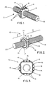
- Fig. 1 is a rear perspective view of one embodiment of the bonding stud of the present invention
- Fig. 2 is a front perspective view of one embodiment of the bonding stud of the present invention.
- Fig. 3 is a front elevation view of one embodiment of the bonding stud of the present invention.
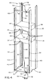
- Fig. 4 is a rearward perspective view of one embodiment of the data center cabinet with the bonding stud of Fig. 1;
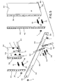
- Fig. 5 is an enlarged exploded rear perspective view of the data center cabinet of Fig. 4;
- Fig. 6 is an enlarged partial side perspective view of the data center cabinet of Fig. 4;
- Fig. 7 is an enlarged partial rear perspective view of the data center cabinet of Fig. 4;
- Fig. 8 is an enlarged partial rear elevation view of the data center cabinet of Fig. 4.
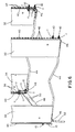
- Fig. 9 is a cross-sectional view of the data center cabinet taken along line 9-9 in Fig. 8.
- Bonding stud 10 includes body 12, dimensioned to geometrically conform to and sized to fit within a cage nut hole within a data cabinet.
- geometrically conform means that body 12 exhibits the same geometric shape as a corresponding cage nut hole.
- the configuration of body 12 advantageously allows bonding stud 10 to resist torque from nuts used with bonding stud 10, thereby preventing loosening of the nuts.
- body 12 includes a square-shaped cross-section. Of course, body 12 may exhibit different shapes to adapt to differently shaped cage nut holes.
- Stop surface in the form of annular shoulder 14, extends from body 12 and provides a positive stop against the frame rail of a data center cabinet or rack.
- One or more projections 16 may extend from annular shoulder 14 and body 12. That is, projections 16 may include a first portion affixed to or in contact with annular shoulder 14 and a second portion affixed to or in contact with body 12. Alternatively, projections 16 may extend from the surface of shoulder 14, without contacting body 12, or could project from body 12, without contacting the surface of shoulder 14. Shoulder 14 can have any shape desired, and may include a thickness t slightly thicker than the shell of a common cage. This helps ensure that a ground strip can be clamped and bonded to bonding stud 10.
- projections 16 may further comprise cutting surface 19, adapted to cut through paint or other non-conductive surfaces, if present, such as those on data center cabinet frame rails and also to create a bond between bonding stud 10 and the base metal of the surface it contacts.
- the size, shape, number and position of projections 16 may vary depending on the contemplated use. Four to twelve projections is typical.
- First threaded stud 18 extends from one surface of body 12 and second threaded stud 20 extends from a second surface of body 12, opposite first threaded stud 18.
- Annular rib 15, comprising edge 17, also extends from annular shoulder 14.
- the compact size of bonding stud 10 allows it to fit within a frame rail of a data center cabinet. It need not use a rack unit, allowing total rack space in the data center cabinet to be used for equipment.
- Bonding stud 10 may be cast or cold-headed out of an electrically conductive material, such as steel. After bonding stud 10 is fashioned, heating in a ceramic furnace with charcoal powder may optionally follow. Heating at a temperature between about 1,500°F and about 1,900°F, followed by quenching, increases the hardness of bonding stud 10. Hardness of bonding stud 10 can be determined with a Rockwell scale, which measures the indentation hardness of materials through the depth of penetration of an indenter. Bonding studs 10 of the present invention may exhibit hardness measurements between about 25.0HR and about 80.0HR. typically between about 45.0HR and about 60.0HR.
- first threaded stud 18 may be between about 0.5 inches and 1.0 inch, more particularly between about 0.7 inches to 0.8 inches and typically about 0.75 inches.
- a length l' of second threaded stud 20 may be between about 0.25 inches to 0.75 inches, more particularly between about 0.3 inches to about 0.7 inches and typically about 0.5 inches.
- Either of first and second studs 18 and 20 may exhibit a diameter d between about 0.15 inches to about 0.30 inches, more particularly about 0.2 inches.
- Each side of body 12, excluding projections 16, may be between about 0.2 inches to 0.4 inches in length, more particularly between about 0.3 inches to 0.35 inches and typically about 0.35 inches.
- Diameter of annular shoulder 14 may be between about 0.4 inches to 0.5 inches, more particularly between about 0.45 inches to 0.47 inches
- Thickness t of annular shoulder 14 may be between about .025 inches to about .040 inches.
- Bonding stud 10 is typically used to mount certain components to a data center cabinet 30, helping to establish and maintain electrical connections throughout. Referring to Figs. 4-9, one embodiment of a data center cabinet 30 using bonding stud 10 is shown.
- Cabinet 30 may include front and rear frame rails 32 and 34, each of which includes numerous cage nut holes 36 typically square in shape, copper ground strip 40, front to rear jumper wires 44, which comprise terminal ends 46 comprising apertures 51, and one ground bar 48.
- FIG. 4 shows two ground bars 48, one on the top and one on the bottom of cabinet 30, only one ground bar 48 is required. If used in an underfloor environment, ground bar 48 is located at the bottom of cabinet 30. Conversely, if used in an overhead environment, ground bar 48 is located at the top of cabinet 30.
- Bonding stud 10 and bonding nuts 11 may be used to secure (1) ground strips 40 and jumper wires 44 to front and rear frame rails 32 and 34, (2) ground bar 48 to rear frame rails 34 and (3) equipment 38 to front and rear frame rails 32 and 34.
- first threaded stud 18 may be used to secure jumper wires 44 to front and rear frame rails 32 and 34.
- Second threaded stud 20 may be used to secure ground strip 40 and ground bar 48 to rear frame rails 34. Second threaded stud 20 may also be used to secure equipment 38 to front and rear frame rails 32 and 34.
- first threaded studs 18 are inserted through cage nut holes 36. Once body 12 is aligned with cage nut holes 36, bonding nuts 11 are then threaded onto first threaded studs 18 until annular shoulder 14 contacts the equipment rail, to secure bonding studs 10 to front and back frame rails 32 and 34. Terminal ends 46 are then inserted over first threaded studs 18 until they stop against bonding nuts 11.
- the common geometric shape between body 12 and cage nut holes 36 helps prevent rotation of bonding stud 10, as bonding nuts 11 are tightened.
- cutting surface 19 of projections 16 bites into front and rear frame rails 32 and 34 and through any paint thereon, to bond front and back frame rails 32 and 34 to bonding studs 10.
- Bonding nuts 11 may also include teeth-like projections (not shown), which can also cut into front and back frame rails 32 and 34, to provide a further bonding connection.
- Second threaded stud 20 may be used to install copper ground strip 40, to overlie a portion of front and rear frame rails 32 and 34 and to secure ground bar 48 to rear frame rails 34.
- Ground strip 40 is constructed of copper and comprises apertures 42 positioned at the same intervals as cage nut holes 36 in front and rear frame rails 32 and 34.
- Second threaded stud 20 may be inserted through apertures 42 in ground strip 40, so that ground strip 40 lies flat against annular shoulder 14, and through cage nut mating apertures 49 in ground bar 48.
- Bonding nuts 11 may be threaded onto second threaded studs 20 to secure ground strip 40 and ground bar 48 into position. As discussed above, bonding nuts 11 may include teeth-like projections, which cut into ground strip 40 and ground bar 48 for enhanced bonding.
- Second threaded stud 20 may also be used to secure equipment 38 to front and rear frame rails 32 and 34. Second threaded stud 20 may be threaded through apertures (not shown) in equipment mounting flange 37, followed by attachment of bonding nut 11 thereto. In this way, equipment 38 can be mounted directly over front to rear jumper wire 44 connections and elsewhere without sacrificing a rack unit. Further, edge 17 of annular rib 15 can cut into equipment mounting flange 37 to enhance electrical conductivity.
- front to back jumper wire 44 provides an electrical connection between front frame rails 32, their corresponding ground strips 40 and rear frame rails 34.
- Ground bar 48 in conjunction with grounding strips 40 and bonding studs 10, establishes and maintains an electrical connection between opposing rear frame rails 34.
- Ground wires 52 and equipment jumper wires 60 may be employed.
- Ground wires 52 may be employed to connect ground bar 48 to common bonding network 56 through terminals 54 on ground wires 52.
- Equipment jumper wires 60 may be employed to connect equipment 38 to at least one of ground strip 40 and ground bar 48 through terminals 62 on equipment jumper wires 60.
- terminals 54 and 62 Similar to terminal ends 46 of jumper wires 44, terminals 54 and 62 include apertures (not shown) for receiving fasteners.
- screws 58 are inserted through these apertures and threaded into threaded holes 50 in ground bar 48.
- screws 64 are inserted through the apertures and threaded into threaded holes in equipment 38, as seen in Fig. 4.
- the heads of screws 58 may also include teeth-like projections on their underside to cut into terminals 54 and 62 and provide an electrical bond therebetween.
- a warning label can be placed on rear frame rails 34 near bonding studs 10 to provide visibility to the ground system.
- the warning label could be colored to stand out, providing visual verification of the need for grounding.
- bonding stud 10 is typically colored green to indicate that it is a grounding device.
Landscapes
- Engineering & Computer Science (AREA)
- General Engineering & Computer Science (AREA)
- Mechanical Engineering (AREA)
- Patch Boards (AREA)
- Casings For Electric Apparatus (AREA)
- Connection Of Plates (AREA)
- Furniture Connections (AREA)
Abstract
Description
- This application claims priority to Provisional Application No.
60/762,678, filed January 27, 2006 - This invention relates to bonding studs and, more particularly, to bonding studs for connecting various parts of a data center cabinet to aid in grounding the data center cabinet.
- There is a need for a data cabinet grounding solution that can provide a sufficient electrical bond between the front and back frame rails and other parts of a data cabinet or rack, with or without occupying a full rack unit.
- The present invention relates to a bonding stud and to data center cabinets or racks employing a bonding stud.
- In one embodiment, the present invention is directed to a bonding stud comprising a body dimensioned to geometrically conform to a cage nut hole within a data center cabinet. A first threaded stud may extend from a first surface of the body and a second threaded stud may extend from a second surface of the body, opposite the first threaded stud. The body may further comprise a stop surface, in the form of an annular shoulder, extending outwardly from the body, as well as a plurality of teeth-like projections, each of which may comprise a first surface in contact with the body and a second surface in contact with the shoulder. The shoulder may extend transversely to a longitudinal axis of the first and second studs, and the teeth may be positioned between the first and second studs.
- In another embodiment, the present invention is directed to a data center cabinet comprising a pair of front frame rails, a pair of rear frame rails, a ground bar connecting the rear frame rails and the above-described bonding stud. The front and rear frame rails may be connected to a ground strip and a front to back jumper wire, by bonding studs and ground nuts. Additionally, each of the rear frame rails may be connected to the ground bar by bonding studs and ground nuts.
- Certain embodiments of the present invention are illustrated by the accompanying figures. It should be understood that the figures are not necessarily to scale and that details not necessary for an understanding of the invention or that render other details difficult to perceive may be omitted. It should be understood, of course, that the invention is not necessarily limited to the particular embodiments illustrated herein.
- Fig. 1 is a rear perspective view of one embodiment of the bonding stud of the present invention;
- Fig. 2 is a front perspective view of one embodiment of the bonding stud of the present invention;
- Fig. 3 is a front elevation view of one embodiment of the bonding stud of the present invention;
- Fig. 4 is a rearward perspective view of one embodiment of the data center cabinet with the bonding stud of Fig. 1;
- Fig. 5 is an enlarged exploded rear perspective view of the data center cabinet of Fig. 4;
- Fig. 6 is an enlarged partial side perspective view of the data center cabinet of Fig. 4;
- Fig. 7 is an enlarged partial rear perspective view of the data center cabinet of Fig. 4;
- Fig. 8 is an enlarged partial rear elevation view of the data center cabinet of Fig. 4; and
- Fig. 9 is a cross-sectional view of the data center cabinet taken along line 9-9 in Fig. 8.
- Referring now to Figs. 1-3, one embodiment of the
bonding stud 10 of the present invention is shown. Bondingstud 10 includesbody 12, dimensioned to geometrically conform to and sized to fit within a cage nut hole within a data cabinet. As used herein, geometrically conform means thatbody 12 exhibits the same geometric shape as a corresponding cage nut hole. The configuration ofbody 12 advantageously allows bondingstud 10 to resist torque from nuts used with bondingstud 10, thereby preventing loosening of the nuts. As shown in Fig. 1,body 12 includes a square-shaped cross-section. Of course,body 12 may exhibit different shapes to adapt to differently shaped cage nut holes. - Stop surface, in the form of
annular shoulder 14, extends frombody 12 and provides a positive stop against the frame rail of a data center cabinet or rack. One ormore projections 16 may extend fromannular shoulder 14 andbody 12. That is,projections 16 may include a first portion affixed to or in contact withannular shoulder 14 and a second portion affixed to or in contact withbody 12. Alternatively,projections 16 may extend from the surface ofshoulder 14, without contactingbody 12, or could project frombody 12, without contacting the surface ofshoulder 14.Shoulder 14 can have any shape desired, and may include a thickness t slightly thicker than the shell of a common cage. This helps ensure that a ground strip can be clamped and bonded to bondingstud 10. - As shown in Fig. 2,
projections 16 may further comprisecutting surface 19, adapted to cut through paint or other non-conductive surfaces, if present, such as those on data center cabinet frame rails and also to create a bond between bondingstud 10 and the base metal of the surface it contacts. The size, shape, number and position ofprojections 16 may vary depending on the contemplated use. Four to twelve projections is typical. - First threaded
stud 18 extends from one surface ofbody 12 and second threadedstud 20 extends from a second surface ofbody 12, opposite first threadedstud 18.Annular rib 15, comprisingedge 17, also extends fromannular shoulder 14. The compact size of bondingstud 10 allows it to fit within a frame rail of a data center cabinet. It need not use a rack unit, allowing total rack space in the data center cabinet to be used for equipment. - Bonding
stud 10 may be cast or cold-headed out of an electrically conductive material, such as steel. After bondingstud 10 is fashioned, heating in a ceramic furnace with charcoal powder may optionally follow. Heating at a temperature between about 1,500°F and about 1,900°F, followed by quenching, increases the hardness ofbonding stud 10. Hardness ofbonding stud 10 can be determined with a Rockwell scale, which measures the indentation hardness of materials through the depth of penetration of an indenter.Bonding studs 10 of the present invention may exhibit hardness measurements between about 25.0HR and about 80.0HR. typically between about 45.0HR and about 60.0HR. - The dimensions of
bonding stud 10 may vary. A length l of first threadedstud 18 may be between about 0.5 inches and 1.0 inch, more particularly between about 0.7 inches to 0.8 inches and typically about 0.75 inches. A length l' of second threadedstud 20 may be between about 0.25 inches to 0.75 inches, more particularly between about 0.3 inches to about 0.7 inches and typically about 0.5 inches. Either of first andsecond studs body 12, excludingprojections 16, may be between about 0.2 inches to 0.4 inches in length, more particularly between about 0.3 inches to 0.35 inches and typically about 0.35 inches. Diameter ofannular shoulder 14 may be between about 0.4 inches to 0.5 inches, more particularly between about 0.45 inches to 0.47 inches Thickness t ofannular shoulder 14 may be between about .025 inches to about .040 inches. -
Bonding stud 10 is typically used to mount certain components to adata center cabinet 30, helping to establish and maintain electrical connections throughout. Referring to Figs. 4-9, one embodiment of adata center cabinet 30 usingbonding stud 10 is shown.Cabinet 30 may include front andrear frame rails cage nut holes 36 typically square in shape,copper ground strip 40, front torear jumper wires 44, which compriseterminal ends 46 comprisingapertures 51, and oneground bar 48. - Although Fig. 4 shows two
ground bars 48, one on the top and one on the bottom ofcabinet 30, only oneground bar 48 is required. If used in an underfloor environment,ground bar 48 is located at the bottom ofcabinet 30. Conversely, if used in an overhead environment,ground bar 48 is located at the top ofcabinet 30. -
Bonding stud 10 andbonding nuts 11 may be used to secure (1) ground strips 40 andjumper wires 44 to front and rear frame rails 32 and 34, (2)ground bar 48 to rear frame rails 34 and (3)equipment 38 to front and rear frame rails 32 and 34. In particular, first threadedstud 18 may be used to securejumper wires 44 to front and rear frame rails 32 and 34. Second threadedstud 20 may be used to secureground strip 40 andground bar 48 to rear frame rails 34. Second threadedstud 20 may also be used to secureequipment 38 to front and rear frame rails 32 and 34. - As shown in Fig. 5, to connect and
bond jumper wires 44 to front and rear frame rails 32 and 34, first threadedstuds 18 are inserted through cage nut holes 36. Oncebody 12 is aligned with cage nut holes 36,bonding nuts 11 are then threaded onto first threadedstuds 18 untilannular shoulder 14 contacts the equipment rail, to securebonding studs 10 to front and back frame rails 32 and 34. Terminal ends 46 are then inserted over first threadedstuds 18 until they stop against bonding nuts 11. - The common geometric shape between
body 12 and cage nut holes 36 helps prevent rotation ofbonding stud 10, asbonding nuts 11 are tightened. In addition, asbonding nuts 11 are tightened, cuttingsurface 19 ofprojections 16 bites into front and rear frame rails 32 and 34 and through any paint thereon, to bond front and back frame rails 32 and 34 tobonding studs 10.Bonding nuts 11 may also include teeth-like projections (not shown), which can also cut into front and back frame rails 32 and 34, to provide a further bonding connection. - Second threaded
stud 20 may be used to installcopper ground strip 40, to overlie a portion of front and rear frame rails 32 and 34 and to secureground bar 48 to rear frame rails 34.Ground strip 40 is constructed of copper and comprisesapertures 42 positioned at the same intervals as cage nut holes 36 in front and rear frame rails 32 and 34. Second threadedstud 20 may be inserted throughapertures 42 inground strip 40, so thatground strip 40 lies flat againstannular shoulder 14, and through cagenut mating apertures 49 inground bar 48.Bonding nuts 11 may be threaded onto second threadedstuds 20 to secureground strip 40 andground bar 48 into position. As discussed above,bonding nuts 11 may include teeth-like projections, which cut intoground strip 40 andground bar 48 for enhanced bonding. - Second threaded
stud 20 may also be used to secureequipment 38 to front and rear frame rails 32 and 34. Second threadedstud 20 may be threaded through apertures (not shown) inequipment mounting flange 37, followed by attachment ofbonding nut 11 thereto. In this way,equipment 38 can be mounted directly over front torear jumper wire 44 connections and elsewhere without sacrificing a rack unit. Further, edge 17 ofannular rib 15 can cut intoequipment mounting flange 37 to enhance electrical conductivity. - The foregoing connections establish electrical continuity between the various components of
cabinet 30. For example, front to backjumper wire 44 provides an electrical connection between front frame rails 32, their corresponding ground strips 40 and rear frame rails 34.Ground bar 48, in conjunction with groundingstrips 40 andbonding studs 10, establishes and maintains an electrical connection between opposing rear frame rails 34. - To further enhance electrical connections throughout
cabinet 30,ground wires 52 andequipment jumper wires 60, shown in Figs. 4 and 5, may be employed.Ground wires 52 may be employed to connectground bar 48 tocommon bonding network 56 throughterminals 54 onground wires 52.Equipment jumper wires 60 may be employed to connectequipment 38 to at least one ofground strip 40 andground bar 48 throughterminals 62 onequipment jumper wires 60. Similar to terminal ends 46 ofjumper wires 44,terminals bond ground wires 52 toground bar 48, screws 58 are inserted through these apertures and threaded into threadedholes 50 inground bar 48. Likewise, to connectequipment jumper wires 60 to one or both ofground strip 40 andground bar 48, screws 64 are inserted through the apertures and threaded into threaded holes inequipment 38, as seen in Fig. 4. The heads ofscrews 58 may also include teeth-like projections on their underside to cut intoterminals - Finally, a warning label can be placed on rear frame rails 34 near
bonding studs 10 to provide visibility to the ground system. The warning label could be colored to stand out, providing visual verification of the need for grounding. Similarly,bonding stud 10 is typically colored green to indicate that it is a grounding device.
Claims (10)
- A bonding stud comprising:a body having a first threaded stud extending from a first surface of the body and a second threaded stud extending from a second surface of the body,the body further having a stop surface extending outwardly from the body and at least one projection, the at least one projection includes a first surface in contact with the body and a second surface in contact with the stop surface.
- The bonding stud of claim 1, wherein the body is dimensioned to geometrically conform to a cage nut hole within a data center cabinet.
- The bonding stud of claim 1, wherein the body has a square-shaped cross-section.
- The bonding stud of claim 1, wherein the stop surface is an annular shoulder.
- The bonding stud of claim 4, wherein the annular shoulder has an annular rib extending from the annular shoulder.
- The bonding stud of claim 1, wherein the at least one projection is positioned between the first and second threaded studs.
- The bonding stud of claim 1, wherein the body has four sides and each side includes between one and three projections.
- The bonding stud of claim 1, wherein the at least one projection comprises between four and twelve projections.
- The bonding stud of claim 1, wherein the at least one projection comprises a tooth having a cutting surface.
- The bonding stud of claim 1, wherein the at least one projection has a triangular-shaped cross-section.
Applications Claiming Priority (2)
| Application Number | Priority Date | Filing Date | Title |
|---|---|---|---|
| US76267806P | 2006-01-27 | 2006-01-27 | |
| US11/625,900 US7568871B2 (en) | 2006-01-27 | 2007-01-23 | Data center cabinet bonding stud |
Publications (3)
| Publication Number | Publication Date |
|---|---|
| EP1814198A2 true EP1814198A2 (en) | 2007-08-01 |
| EP1814198A3 EP1814198A3 (en) | 2014-04-02 |
| EP1814198B1 EP1814198B1 (en) | 2018-05-30 |
Family
ID=38057373
Family Applications (1)
| Application Number | Title | Priority Date | Filing Date |
|---|---|---|---|
| EP07250329.5A Not-in-force EP1814198B1 (en) | 2006-01-27 | 2007-01-26 | Data center cabinet bonding stud |
Country Status (2)
| Country | Link |
|---|---|
| US (1) | US7568871B2 (en) |
| EP (1) | EP1814198B1 (en) |
Families Citing this family (52)
| Publication number | Priority date | Publication date | Assignee | Title |
|---|---|---|---|---|
| FR2877774B1 (en) * | 2004-11-08 | 2010-11-05 | Airbus France | CONNECTOR ASSEMBLY FOR AIRCRAFT |
| RU2418206C2 (en) * | 2006-01-05 | 2011-05-10 | Профиль-Фербиндунгстехник Гмбх Унд Ко. Кг | Fastening element, subassembly, made of fastening element and sheet metal parts, and also method to fix fastening element onto sheet metal parts |
| US7780198B2 (en) * | 2008-03-27 | 2010-08-24 | International Truck Intellectual Property Company, Llc | Independently adjustable chassis skirt mounting assembly |
| US20120133510A1 (en) * | 2010-11-30 | 2012-05-31 | Panduit Corp. | Physical infrastructure management system having an integrated cabinet |
| US8636457B2 (en) * | 2009-06-25 | 2014-01-28 | Robert W. Connors | Two-way fastener |
| DE102009057548A1 (en) * | 2009-12-09 | 2011-06-16 | Dr. Ing. H.C. F. Porsche Aktiengesellschaft | repair |
| US9724140B2 (en) | 2010-06-02 | 2017-08-08 | Wright Medical Technology, Inc. | Tapered, cylindrical cruciform hammer toe implant and method |
| US8608785B2 (en) | 2010-06-02 | 2013-12-17 | Wright Medical Technology, Inc. | Hammer toe implant with expansion portion for retrograde approach |
| US9498273B2 (en) | 2010-06-02 | 2016-11-22 | Wright Medical Technology, Inc. | Orthopedic implant kit |
| US9072564B2 (en) * | 2010-06-02 | 2015-07-07 | Wright Medical Technology, Inc. | Hammer toe implant and method |
| DE102010038347A1 (en) * | 2010-07-23 | 2012-01-26 | Bayerische Motoren Werke Aktiengesellschaft | Device for supplying power to a housing for receiving at least one energy storage module |
| US9611652B2 (en) | 2011-02-25 | 2017-04-04 | Dustin M. M. Haddock | Mounting device for building surfaces having elongated mounting slot |
| US20130032310A1 (en) * | 2011-08-02 | 2013-02-07 | Power Distribution Inc. | Transportable, environmentally-controlled equipment enclosure |
| AT511832B1 (en) * | 2011-09-01 | 2013-03-15 | Blum Gmbh Julius | FASTENING DEVICE FOR A FURNITURE FITTING |
| US20130168525A1 (en) | 2011-12-29 | 2013-07-04 | Dustin M.M. Haddock | Mounting device for nail strip panels |
| US20130170895A1 (en) * | 2012-01-03 | 2013-07-04 | Ying-Chih Tseng | Floating fastener with expanded application flexibility |
| JP5957257B2 (en) * | 2012-03-27 | 2016-07-27 | 住友林業株式会社 | Wood member joint structure |
| US8945232B2 (en) | 2012-12-31 | 2015-02-03 | Wright Medical Technology, Inc. | Ball and socket implants for correction of hammer toes and claw toes |
| AT16616U1 (en) * | 2013-03-13 | 2020-02-15 | Blum Gmbh Julius | Fastening device for a furniture fitting |
| US9724139B2 (en) | 2013-10-01 | 2017-08-08 | Wright Medical Technology, Inc. | Hammer toe implant and method |
| US10247222B2 (en) * | 2013-11-13 | 2019-04-02 | Inter-Join Pty Ltd. | Fastener system with fastener extension and driving tool |
| US9474561B2 (en) | 2013-11-19 | 2016-10-25 | Wright Medical Technology, Inc. | Two-wire technique for installing hammertoe implant |
| USD753477S1 (en) * | 2013-12-18 | 2016-04-12 | Adjustable Clamp Company | Dual threaded chucking screw |
| US9498266B2 (en) | 2014-02-12 | 2016-11-22 | Wright Medical Technology, Inc. | Intramedullary implant, system, and method for inserting an implant into a bone |
| US9545274B2 (en) | 2014-02-12 | 2017-01-17 | Wright Medical Technology, Inc. | Intramedullary implant, system, and method for inserting an implant into a bone |
| EP2910801B1 (en) * | 2014-02-24 | 2016-11-09 | GESIPA Blindniettechnik GmbH | Blind rivet fastener |
| US9680239B2 (en) | 2014-04-23 | 2017-06-13 | Ramco Specialties, Inc. | Grounding stud and electrical connections |
| WO2016043751A1 (en) | 2014-09-18 | 2016-03-24 | Wright Medical Technology, Inc. | Hammertoe implant and instrument |
| CA2889595C (en) | 2014-12-19 | 2018-01-16 | Wright Medical Technology, Inc. | Intramedullary anchor for interphalangeal arthrodesis |
| WO2017114935A1 (en) * | 2015-12-30 | 2017-07-06 | CommScope Connectivity Belgium BVBA | Housing with self-orienting grounding stud |
| WO2018023016A1 (en) | 2016-07-29 | 2018-02-01 | Haddock Dustin M M | Trapezoidal rib mounting bracket with flexible legs |
| USD832222S1 (en) * | 2016-09-26 | 2018-10-30 | Switchboard Apparatus, Inc. | Insulator |
| WO2018081722A1 (en) | 2016-10-31 | 2018-05-03 | Haddock Dustin M M | Metal panel electrical bonding clip |
| AU2018348090B2 (en) | 2017-10-09 | 2021-11-18 | Rmh Tech Llc | Rail assembly with invertible side-mount adapter for direct and indirect mounting applications |
| EP3737588B1 (en) * | 2018-01-02 | 2022-01-12 | Volvo Truck Corporation | A holder arrangement comprising a bracket and a spacer, and a manufacturing method for manufacturing a spacer |
| US10903785B2 (en) | 2018-03-21 | 2021-01-26 | Rmh Tech Llc | PV module mounting assembly with clamp/standoff arrangement |
| US10876556B2 (en) * | 2018-03-26 | 2020-12-29 | GM Global Technology Operations LLC | Double-ended dual attached fastener |
| CN113412396A (en) | 2018-12-14 | 2021-09-17 | Rmh技术有限责任公司 | Mounting device for nail belt panel |
| JP7156124B2 (en) * | 2019-03-25 | 2022-10-19 | 株式会社Jvcケンウッド | Stud pins and stud pin crimping methods |
| CN115917095A (en) | 2020-03-16 | 2023-04-04 | Rmh技术有限责任公司 | Mounting devices for metal roofs |
| US11041310B1 (en) | 2020-03-17 | 2021-06-22 | Rmh Tech Llc | Mounting device for controlling uplift of a metal roof |
| CA3184245A1 (en) * | 2020-06-30 | 2022-01-06 | Lance NILL | Offset attachment device |
| BR112023000401A2 (en) | 2020-07-09 | 2023-01-31 | Rmh Tech Llc | SYSTEM, DEVICE AND ASSEMBLY METHOD |
| DE102020124107A1 (en) | 2020-09-16 | 2022-03-17 | E.On Se | ground connector |
| US12483185B2 (en) | 2021-09-09 | 2025-11-25 | Rmh Tech Llc | Torque actuated rail assembly |
| US12519418B2 (en) | 2022-07-06 | 2026-01-06 | Rmh Tech Llc | PV module mounting assembly with clamp / standoff arrangement |
| USD1075493S1 (en) | 2022-07-06 | 2025-05-20 | Rmh Tech Llc | Clamp for a photovoltaic module mounting assembly |
| CN121358993A (en) | 2023-04-14 | 2026-01-16 | Rmh技术有限责任公司 | Mounting device for metal panels |
| USD1113406S1 (en) | 2023-04-14 | 2026-02-17 | Rmh Tech Llc | Mounting device |
| US12084903B1 (en) * | 2023-04-18 | 2024-09-10 | Brian Goldwitz | Door alignment pin bolt with the thread on the top and the bottom |
| EP4496139B1 (en) * | 2023-07-15 | 2025-10-29 | Aptiv Technologies AG | Connector assembly and method of assembling such a connector assembly |
| USD1109686S1 (en) | 2023-08-10 | 2026-01-20 | Rmh Tech Llc | Mount for a component of a photovoltaic assembly |
Family Cites Families (30)
| Publication number | Priority date | Publication date | Assignee | Title |
|---|---|---|---|---|
| US1855447A (en) | 1929-01-17 | 1932-04-26 | Charles H Hagstedt | Coupling for outlet boxes |
| US2017493A (en) | 1933-12-26 | 1935-10-15 | John B Glowacki | Nut |
| US2741289A (en) * | 1952-09-25 | 1956-04-10 | Harlow B Grow | Threaded fastener having deformable locking flange with biting teeth |
| US3255797A (en) | 1964-06-15 | 1966-06-14 | Warren R Attwood | Structural assemblies |
| US3383646A (en) | 1966-07-01 | 1968-05-14 | John D. Otto | Electrical terminal clamp |
| US3535678A (en) | 1968-06-19 | 1970-10-20 | Deutsch Fastener Corp | Electrical terminal |
| US3640326A (en) | 1969-10-17 | 1972-02-08 | Armco Steel Corp | Bolt |
| US3850501A (en) * | 1973-04-09 | 1974-11-26 | Gen Electric | Feedthrough electrical terminal for hollow liquid cooled shaft of a dynamoelectric machine |
| US3861774A (en) | 1973-06-14 | 1975-01-21 | Lockheed Aircraft Corp | Coined ground stud |
| GB1478951A (en) | 1975-04-17 | 1977-07-06 | Richards Fasteners Ltd C | Self-locking screw threads |
| US4223585A (en) * | 1977-06-09 | 1980-09-23 | Illinois Tool Works Inc. | Double-ended stud with combined driving and locking means |
| US4304503A (en) | 1977-09-07 | 1981-12-08 | Semblex Corporation | Opposite threaded stud |
| US4170069A (en) * | 1978-02-27 | 1979-10-09 | Michael Katsanevas | Wheel lug nut tool |
| US5207588A (en) * | 1980-02-02 | 1993-05-04 | Multifastener Corporation | Electrical grounding stud |
| US5441417A (en) * | 1981-01-28 | 1995-08-15 | Multifastener Corporation | Electrical grounding stud |
| US4410226A (en) | 1981-08-10 | 1983-10-18 | General Motors Corporation | Junction box and connector arrangement |
| JPS5851479A (en) | 1981-09-18 | 1983-03-26 | 富士通株式会社 | Terminal board for power source |
| US4764066A (en) | 1985-04-22 | 1988-08-16 | Farley Metals, Inc. | Light gauge self-tapping sheet metal screw |
| US4744765A (en) | 1987-06-19 | 1988-05-17 | John DeLeo | High voltage ground stud |
| US4820235A (en) | 1987-07-28 | 1989-04-11 | Hirsh Company | Threaded fastener |
| SE9102006D0 (en) | 1991-06-28 | 1991-06-28 | Volvo Ab | ELKONTAKTMUTTER |
| US5442133A (en) | 1993-09-08 | 1995-08-15 | Emhart Inc. | Grounding stud/nut |
| US5639268A (en) * | 1995-11-24 | 1997-06-17 | Julian Electric, Inc. | Through the wall connector |
| US5928006A (en) | 1996-12-26 | 1999-07-27 | Franks, Jr.; George J. | Clamping bracket for a grounding system |
| US6241444B1 (en) | 1997-08-15 | 2001-06-05 | Ronald C. Clarke | Apparatus for sealing a milling liner to a milling shell with improved sealing capacity |
| US6186717B1 (en) | 1999-04-28 | 2001-02-13 | Fairchild Holding Corp | Electrical terminal blind grounding stud fastener system |
| JP3354120B2 (en) | 1999-10-05 | 2002-12-09 | エスエムケイ株式会社 | Terminal connector and its manufacturing method |
| US6746285B2 (en) | 2001-02-20 | 2004-06-08 | Newfrey Llc | Grounding stud |
| SE0100562D0 (en) | 2001-02-20 | 2001-02-20 | Volvo Lastvagnar Ab | Earth Element |
| US6592311B2 (en) * | 2001-07-19 | 2003-07-15 | Fabristeel Products, Inc. | Double-ended self-attaching stud |
-
2007
- 2007-01-23 US US11/625,900 patent/US7568871B2/en active Active
- 2007-01-26 EP EP07250329.5A patent/EP1814198B1/en not_active Not-in-force
Also Published As
| Publication number | Publication date |
|---|---|
| EP1814198B1 (en) | 2018-05-30 |
| EP1814198A3 (en) | 2014-04-02 |
| US20070177959A1 (en) | 2007-08-02 |
| US7568871B2 (en) | 2009-08-04 |
Similar Documents
| Publication | Publication Date | Title |
|---|---|---|
| US7568871B2 (en) | Data center cabinet bonding stud | |
| US8529277B2 (en) | Flex to flex connection device | |
| EP2108848A1 (en) | Earthing clamp for beam | |
| US7670153B2 (en) | Electrical connector | |
| EP0945934B1 (en) | Electrical coupler for detachable interconnection between a main unit and an external unit | |
| US7241152B2 (en) | System for electrically connecting and fastening at least one plate-type electrical conductor to a support piece | |
| CA2746097C (en) | Ground connector | |
| AU2017268478B2 (en) | Distribution block with integrated surge protective device | |
| US10673190B2 (en) | Pad extending member | |
| EP1876674A1 (en) | Insulated jumper in particular for terminal blocks of switchboards | |
| EP1947746A2 (en) | Modular method and system for insulated bus bar cable harness termination concept | |
| CN110299625A (en) | Electrical equipment and earthing method for this equipment | |
| FI75692C (en) | Grounding system for appliance cabinets. | |
| WO2001037400A2 (en) | Electric device grounding system | |
| US4575178A (en) | Connector for securing wires to a battery terminal | |
| DE202011004344U1 (en) | Device for detecting the heat output of a radiator | |
| WO2013141858A1 (en) | Flex to flex connection device | |
| JP2691027B2 (en) | Information processing device | |
| US12288948B1 (en) | Power cable plug connector | |
| FR2848029B1 (en) | DEVICE FOR ELECTRICALLY CONNECTING A MODULAR ELECTRICAL APPARATUS TO A CONNECTING COMB OR THE LIKE | |
| KR20190004404A (en) | Distribution board with busbar | |
| JP6989893B2 (en) | Temporary bond device for rails | |
| US20030157822A1 (en) | Modular ground bar system | |
| JPH0526906Y2 (en) | ||
| EP3419126A1 (en) | Protection device for interconnecting electrical busbars |
Legal Events
| Date | Code | Title | Description |
|---|---|---|---|
| PUAI | Public reference made under article 153(3) epc to a published international application that has entered the european phase |
Free format text: ORIGINAL CODE: 0009012 |
|
| AK | Designated contracting states |
Kind code of ref document: A2 Designated state(s): AT BE BG CH CY CZ DE DK EE ES FI FR GB GR HU IE IS IT LI LT LU LV MC NL PL PT RO SE SI SK TR |
|
| AX | Request for extension of the european patent |
Extension state: AL BA HR MK YU |
|
| PUAL | Search report despatched |
Free format text: ORIGINAL CODE: 0009013 |
|
| AK | Designated contracting states |
Kind code of ref document: A3 Designated state(s): AT BE BG CH CY CZ DE DK EE ES FI FR GB GR HU IE IS IT LI LT LU LV MC NL PL PT RO SE SI SK TR |
|
| AX | Request for extension of the european patent |
Extension state: AL BA HR MK RS |
|
| RIC1 | Information provided on ipc code assigned before grant |
Ipc: H01R 4/34 20060101ALN20140224BHEP Ipc: H01R 4/64 20060101AFI20140224BHEP |
|
| 17P | Request for examination filed |
Effective date: 20141002 |
|
| RBV | Designated contracting states (corrected) |
Designated state(s): AT BE BG CH CY CZ DE DK EE ES FI FR GB GR HU IE IS IT LI LT LU LV MC NL PL PT RO SE SI SK TR |
|
| RBV | Designated contracting states (corrected) |
Designated state(s): AT BE BG CH CY CZ DE DK EE ES FI FR GB GR HU IE IS IT LI LT LU LV MC NL PL PT RO SE SI SK TR |
|
| AKX | Designation fees paid |
Designated state(s): AT BE BG CH CY CZ DE DK EE ES FI FR GB GR HU IE IS IT LI LT LU LV MC NL PL PT RO SE SI SK TR |
|
| AXX | Extension fees paid |
Extension state: BA Extension state: MK Extension state: RS Extension state: HR Extension state: AL |
|
| 17Q | First examination report despatched |
Effective date: 20160504 |
|
| GRAP | Despatch of communication of intention to grant a patent |
Free format text: ORIGINAL CODE: EPIDOSNIGR1 |
|
| STAA | Information on the status of an ep patent application or granted ep patent |
Free format text: STATUS: GRANT OF PATENT IS INTENDED |
|
| RIC1 | Information provided on ipc code assigned before grant |
Ipc: F16B 35/04 20060101ALN20171107BHEP Ipc: H01R 4/34 20060101ALN20171107BHEP Ipc: F16B 5/02 20060101ALI20171107BHEP Ipc: H01R 4/64 20060101AFI20171107BHEP |
|
| INTG | Intention to grant announced |
Effective date: 20171201 |
|
| GRAS | Grant fee paid |
Free format text: ORIGINAL CODE: EPIDOSNIGR3 |
|
| STAA | Information on the status of an ep patent application or granted ep patent |
Free format text: STATUS: EXAMINATION IS IN PROGRESS |
|
| GRAJ | Information related to disapproval of communication of intention to grant by the applicant or resumption of examination proceedings by the epo deleted |
Free format text: ORIGINAL CODE: EPIDOSDIGR1 |
|
| GRAL | Information related to payment of fee for publishing/printing deleted |
Free format text: ORIGINAL CODE: EPIDOSDIGR3 |
|
| GRAR | Information related to intention to grant a patent recorded |
Free format text: ORIGINAL CODE: EPIDOSNIGR71 |
|
| STAA | Information on the status of an ep patent application or granted ep patent |
Free format text: STATUS: GRANT OF PATENT IS INTENDED |
|
| GRAA | (expected) grant |
Free format text: ORIGINAL CODE: 0009210 |
|
| STAA | Information on the status of an ep patent application or granted ep patent |
Free format text: STATUS: THE PATENT HAS BEEN GRANTED |
|
| INTC | Intention to grant announced (deleted) | ||
| RIC1 | Information provided on ipc code assigned before grant |
Ipc: H01R 4/64 20060101AFI20180411BHEP Ipc: F16B 35/04 20060101ALN20180411BHEP Ipc: H01R 4/34 20060101ALN20180411BHEP Ipc: F16B 5/02 20060101ALI20180411BHEP |
|
| AK | Designated contracting states |
Kind code of ref document: B1 Designated state(s): AT BE BG CH CY CZ DE DK EE ES FI FR GB GR HU IE IS IT LI LT LU LV MC NL PL PT RO SE SI SK TR |
|
| INTG | Intention to grant announced |
Effective date: 20180424 |
|
| REG | Reference to a national code |
Ref country code: GB Ref legal event code: FG4D |
|
| REG | Reference to a national code |
Ref country code: CH Ref legal event code: EP |
|
| REG | Reference to a national code |
Ref country code: AT Ref legal event code: REF Ref document number: 1004558 Country of ref document: AT Kind code of ref document: T Effective date: 20180615 |
|
| REG | Reference to a national code |
Ref country code: IE Ref legal event code: FG4D |
|
| REG | Reference to a national code |
Ref country code: DE Ref legal event code: R096 Ref document number: 602007054959 Country of ref document: DE |
|
| REG | Reference to a national code |
Ref country code: NL Ref legal event code: MP Effective date: 20180530 |
|
| REG | Reference to a national code |
Ref country code: LT Ref legal event code: MG4D |
|
| PG25 | Lapsed in a contracting state [announced via postgrant information from national office to epo] |
Ref country code: ES Free format text: LAPSE BECAUSE OF FAILURE TO SUBMIT A TRANSLATION OF THE DESCRIPTION OR TO PAY THE FEE WITHIN THE PRESCRIBED TIME-LIMIT Effective date: 20180530 Ref country code: FI Free format text: LAPSE BECAUSE OF FAILURE TO SUBMIT A TRANSLATION OF THE DESCRIPTION OR TO PAY THE FEE WITHIN THE PRESCRIBED TIME-LIMIT Effective date: 20180530 Ref country code: SE Free format text: LAPSE BECAUSE OF FAILURE TO SUBMIT A TRANSLATION OF THE DESCRIPTION OR TO PAY THE FEE WITHIN THE PRESCRIBED TIME-LIMIT Effective date: 20180530 Ref country code: LT Free format text: LAPSE BECAUSE OF FAILURE TO SUBMIT A TRANSLATION OF THE DESCRIPTION OR TO PAY THE FEE WITHIN THE PRESCRIBED TIME-LIMIT Effective date: 20180530 Ref country code: CY Free format text: LAPSE BECAUSE OF FAILURE TO SUBMIT A TRANSLATION OF THE DESCRIPTION OR TO PAY THE FEE WITHIN THE PRESCRIBED TIME-LIMIT Effective date: 20180530 Ref country code: BG Free format text: LAPSE BECAUSE OF FAILURE TO SUBMIT A TRANSLATION OF THE DESCRIPTION OR TO PAY THE FEE WITHIN THE PRESCRIBED TIME-LIMIT Effective date: 20180830 |
|
| PG25 | Lapsed in a contracting state [announced via postgrant information from national office to epo] |
Ref country code: GR Free format text: LAPSE BECAUSE OF FAILURE TO SUBMIT A TRANSLATION OF THE DESCRIPTION OR TO PAY THE FEE WITHIN THE PRESCRIBED TIME-LIMIT Effective date: 20180831 Ref country code: LV Free format text: LAPSE BECAUSE OF FAILURE TO SUBMIT A TRANSLATION OF THE DESCRIPTION OR TO PAY THE FEE WITHIN THE PRESCRIBED TIME-LIMIT Effective date: 20180530 |
|
| REG | Reference to a national code |
Ref country code: AT Ref legal event code: MK05 Ref document number: 1004558 Country of ref document: AT Kind code of ref document: T Effective date: 20180530 |
|
| PG25 | Lapsed in a contracting state [announced via postgrant information from national office to epo] |
Ref country code: NL Free format text: LAPSE BECAUSE OF FAILURE TO SUBMIT A TRANSLATION OF THE DESCRIPTION OR TO PAY THE FEE WITHIN THE PRESCRIBED TIME-LIMIT Effective date: 20180530 |
|
| PG25 | Lapsed in a contracting state [announced via postgrant information from national office to epo] |
Ref country code: RO Free format text: LAPSE BECAUSE OF FAILURE TO SUBMIT A TRANSLATION OF THE DESCRIPTION OR TO PAY THE FEE WITHIN THE PRESCRIBED TIME-LIMIT Effective date: 20180530 Ref country code: SK Free format text: LAPSE BECAUSE OF FAILURE TO SUBMIT A TRANSLATION OF THE DESCRIPTION OR TO PAY THE FEE WITHIN THE PRESCRIBED TIME-LIMIT Effective date: 20180530 Ref country code: CZ Free format text: LAPSE BECAUSE OF FAILURE TO SUBMIT A TRANSLATION OF THE DESCRIPTION OR TO PAY THE FEE WITHIN THE PRESCRIBED TIME-LIMIT Effective date: 20180530 Ref country code: EE Free format text: LAPSE BECAUSE OF FAILURE TO SUBMIT A TRANSLATION OF THE DESCRIPTION OR TO PAY THE FEE WITHIN THE PRESCRIBED TIME-LIMIT Effective date: 20180530 Ref country code: AT Free format text: LAPSE BECAUSE OF FAILURE TO SUBMIT A TRANSLATION OF THE DESCRIPTION OR TO PAY THE FEE WITHIN THE PRESCRIBED TIME-LIMIT Effective date: 20180530 Ref country code: DK Free format text: LAPSE BECAUSE OF FAILURE TO SUBMIT A TRANSLATION OF THE DESCRIPTION OR TO PAY THE FEE WITHIN THE PRESCRIBED TIME-LIMIT Effective date: 20180530 Ref country code: PL Free format text: LAPSE BECAUSE OF FAILURE TO SUBMIT A TRANSLATION OF THE DESCRIPTION OR TO PAY THE FEE WITHIN THE PRESCRIBED TIME-LIMIT Effective date: 20180530 |
|
| PG25 | Lapsed in a contracting state [announced via postgrant information from national office to epo] |
Ref country code: IT Free format text: LAPSE BECAUSE OF FAILURE TO SUBMIT A TRANSLATION OF THE DESCRIPTION OR TO PAY THE FEE WITHIN THE PRESCRIBED TIME-LIMIT Effective date: 20180530 |
|
| REG | Reference to a national code |
Ref country code: DE Ref legal event code: R097 Ref document number: 602007054959 Country of ref document: DE |
|
| PLBE | No opposition filed within time limit |
Free format text: ORIGINAL CODE: 0009261 |
|
| STAA | Information on the status of an ep patent application or granted ep patent |
Free format text: STATUS: NO OPPOSITION FILED WITHIN TIME LIMIT |
|
| 26N | No opposition filed |
Effective date: 20190301 |
|
| PG25 | Lapsed in a contracting state [announced via postgrant information from national office to epo] |
Ref country code: SI Free format text: LAPSE BECAUSE OF FAILURE TO SUBMIT A TRANSLATION OF THE DESCRIPTION OR TO PAY THE FEE WITHIN THE PRESCRIBED TIME-LIMIT Effective date: 20180530 |
|
| PG25 | Lapsed in a contracting state [announced via postgrant information from national office to epo] |
Ref country code: MC Free format text: LAPSE BECAUSE OF FAILURE TO SUBMIT A TRANSLATION OF THE DESCRIPTION OR TO PAY THE FEE WITHIN THE PRESCRIBED TIME-LIMIT Effective date: 20180530 |
|
| REG | Reference to a national code |
Ref country code: CH Ref legal event code: PL |
|
| PG25 | Lapsed in a contracting state [announced via postgrant information from national office to epo] |
Ref country code: LU Free format text: LAPSE BECAUSE OF NON-PAYMENT OF DUE FEES Effective date: 20190126 |
|
| REG | Reference to a national code |
Ref country code: BE Ref legal event code: MM Effective date: 20190131 |
|
| REG | Reference to a national code |
Ref country code: IE Ref legal event code: MM4A |
|
| PG25 | Lapsed in a contracting state [announced via postgrant information from national office to epo] |
Ref country code: BE Free format text: LAPSE BECAUSE OF NON-PAYMENT OF DUE FEES Effective date: 20190131 |
|
| PG25 | Lapsed in a contracting state [announced via postgrant information from national office to epo] |
Ref country code: LI Free format text: LAPSE BECAUSE OF NON-PAYMENT OF DUE FEES Effective date: 20190131 Ref country code: CH Free format text: LAPSE BECAUSE OF NON-PAYMENT OF DUE FEES Effective date: 20190131 |
|
| PG25 | Lapsed in a contracting state [announced via postgrant information from national office to epo] |
Ref country code: IE Free format text: LAPSE BECAUSE OF NON-PAYMENT OF DUE FEES Effective date: 20190126 |
|
| PG25 | Lapsed in a contracting state [announced via postgrant information from national office to epo] |
Ref country code: TR Free format text: LAPSE BECAUSE OF FAILURE TO SUBMIT A TRANSLATION OF THE DESCRIPTION OR TO PAY THE FEE WITHIN THE PRESCRIBED TIME-LIMIT Effective date: 20180530 |
|
| PG25 | Lapsed in a contracting state [announced via postgrant information from national office to epo] |
Ref country code: PT Free format text: LAPSE BECAUSE OF FAILURE TO SUBMIT A TRANSLATION OF THE DESCRIPTION OR TO PAY THE FEE WITHIN THE PRESCRIBED TIME-LIMIT Effective date: 20181001 |
|
| PG25 | Lapsed in a contracting state [announced via postgrant information from national office to epo] |
Ref country code: IS Free format text: LAPSE BECAUSE OF FAILURE TO SUBMIT A TRANSLATION OF THE DESCRIPTION OR TO PAY THE FEE WITHIN THE PRESCRIBED TIME-LIMIT Effective date: 20180930 |
|
| PG25 | Lapsed in a contracting state [announced via postgrant information from national office to epo] |
Ref country code: HU Free format text: LAPSE BECAUSE OF FAILURE TO SUBMIT A TRANSLATION OF THE DESCRIPTION OR TO PAY THE FEE WITHIN THE PRESCRIBED TIME-LIMIT; INVALID AB INITIO Effective date: 20070126 |
|
| PGFP | Annual fee paid to national office [announced via postgrant information from national office to epo] |
Ref country code: DE Payment date: 20240129 Year of fee payment: 18 Ref country code: GB Payment date: 20240129 Year of fee payment: 18 |
|
| PGFP | Annual fee paid to national office [announced via postgrant information from national office to epo] |
Ref country code: FR Payment date: 20240125 Year of fee payment: 18 |
|
| REG | Reference to a national code |
Ref country code: DE Ref legal event code: R119 Ref document number: 602007054959 Country of ref document: DE |
|
| GBPC | Gb: european patent ceased through non-payment of renewal fee |
Effective date: 20250126 |
|
| PG25 | Lapsed in a contracting state [announced via postgrant information from national office to epo] |
Ref country code: DE Free format text: LAPSE BECAUSE OF NON-PAYMENT OF DUE FEES Effective date: 20250801 |
|
| PG25 | Lapsed in a contracting state [announced via postgrant information from national office to epo] |
Ref country code: GB Free format text: LAPSE BECAUSE OF NON-PAYMENT OF DUE FEES Effective date: 20250126 |
|
| PG25 | Lapsed in a contracting state [announced via postgrant information from national office to epo] |
Ref country code: FR Free format text: LAPSE BECAUSE OF NON-PAYMENT OF DUE FEES Effective date: 20250131 |