EP1814125A1 - Boiling water reactor control rod - Google Patents
Boiling water reactor control rod Download PDFInfo
- Publication number
- EP1814125A1 EP1814125A1 EP06126832A EP06126832A EP1814125A1 EP 1814125 A1 EP1814125 A1 EP 1814125A1 EP 06126832 A EP06126832 A EP 06126832A EP 06126832 A EP06126832 A EP 06126832A EP 1814125 A1 EP1814125 A1 EP 1814125A1
- Authority
- EP
- European Patent Office
- Prior art keywords
- control rod
- planar
- absorber tube
- cruciform
- absorber
- Prior art date
- Legal status (The legal status is an assumption and is not a legal conclusion. Google has not performed a legal analysis and makes no representation as to the accuracy of the status listed.)
- Granted
Links
Images


Classifications
-
- G—PHYSICS
- G21—NUCLEAR PHYSICS; NUCLEAR ENGINEERING
- G21C—NUCLEAR REACTORS
- G21C7/00—Control of nuclear reaction
- G21C7/06—Control of nuclear reaction by application of neutron-absorbing material, i.e. material with absorption cross-section very much in excess of reflection cross-section
- G21C7/08—Control of nuclear reaction by application of neutron-absorbing material, i.e. material with absorption cross-section very much in excess of reflection cross-section by displacement of solid control elements, e.g. control rods
- G21C7/10—Construction of control elements
- G21C7/113—Control elements made of flat elements; Control elements having cruciform cross-section
-
- Y—GENERAL TAGGING OF NEW TECHNOLOGICAL DEVELOPMENTS; GENERAL TAGGING OF CROSS-SECTIONAL TECHNOLOGIES SPANNING OVER SEVERAL SECTIONS OF THE IPC; TECHNICAL SUBJECTS COVERED BY FORMER USPC CROSS-REFERENCE ART COLLECTIONS [XRACs] AND DIGESTS
- Y02—TECHNOLOGIES OR APPLICATIONS FOR MITIGATION OR ADAPTATION AGAINST CLIMATE CHANGE
- Y02E—REDUCTION OF GREENHOUSE GAS [GHG] EMISSIONS, RELATED TO ENERGY GENERATION, TRANSMISSION OR DISTRIBUTION
- Y02E30/00—Energy generation of nuclear origin
- Y02E30/30—Nuclear fission reactors
Definitions
- Nuclear reactors typically include control rods containing materials for neutron absorption and for either shutting down or shaping nuclear reactions.
- Conventional control rods (or control blades) in Boiling Water Reactors (BWR) have a cruciform shape and pass in complementary cruciform shaped interstices (called fuel channel gaps) between fuel assembles of fuel rods.
- Prior art control rods consist of a plurality of elongated members, configured side-by-side to form a planar member. These elongated members, known as absorber tubes, are sealed at both ends and may contain capsules containing boron carbide powder, or other neutron absorbing materials such as hafnium rods.
- planar members each consisting of a plurality of absorber tubes, are welded to a central generally cruciform member, to form a cruciform shaped control rod.
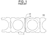
- U.S. Patent Nos. 4,929,412 and 4,902,470 disclose a control rod 100 including an absorber tube T with four discrete right angle corners. As shown in FIG. 1, adjacent absorber tubes T are welded together at corners 10, where reference numeral 20 indicates welded material between adjacent absorber tubes.
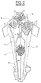
- FIG. 2 is a perspective view illustrating a control rod, coming up from under four side-by-side fuel channels, for absorbing neutrons in the control of a nuclear reaction.
- FIG. 2 illustrates how fuel assemblies are arranged around control rods on a BWR.
- the nuclear reactors have fuel channels 14 containing fuel rods 16. Interior of the fuel rods 16 are placed the nuclear fuel pellets which generate the chain nuclear reaction. BWR type reactors introduce the control rods from the bottom towards the top.
- Such a control rod R is shown in FIG. 2 coming up between the respective fuel channels 14 separating fuel assemblies of fuel rods 16.
- An example embodiment of the present invention is directed to a control rod having a plurality of elongated members for absorbing neutrons within a nuclear reactor to control a nuclear reaction.
- Each elongated member may include a cylindrical inner capsule configured to contain neutron absorbing material therein, and may include an absorber tube enclosing the cylindrical inner capsule.
- the absorber tube may have an outer surface configured with a plurality of generally flat, planar sides between adjacent rounded corners, or adjacent planar corners.
- the control rod includes four planar members extending from a central vertical axis to form a cruciform shape.
- Each of the planar members may further include a plurality of elongated members configured in side-by-side relation.
- Each elongated member may further include a cylindrical inner capsule configured to contain neutron absorbing material therein, and an absorber tube enclosing the cylindrical inner capsule.
- the absorber tube may have an outer surface configured with a plurality of generally flat, planar sides between adjacent rounded corners, or adjacent planar corners.
- the control rod may include a cruciform-shaped tie rod segment provided along the central vertical axis to brace the four planar members with respect to each other, a velocity limiter attached to the control rod at a lower end thereof and handle to the control rod at an upper end thereof.
- the absorber tube may include an elongate member having a generally cylindrical inner surface enclosing an inner capsule that is configured to contain neutron absorbing material therein.
- the elongate member has an outer surface configured to have generally flat, planar sides. Each planar side is arranged between adjacent rounded corners, or adjacent planar corners, of the outer surface of the elongate member.
- FIG. 3 illustrates a horizontal sectional view of an absorber tube according to an example embodiment of the present invention.
- the control rod may be comprised of a plurality of elongate members; a cross-section of a single elongate member is shown in FIG. 3.
- the elongate member 200 may include an absorber tube 300 having a round inside diameter and enclosing a capsule 201, and a generally round outside diameter with generally flat, planar areas or sides between four (4) rounded corners, as shown in FIG. 3.
- the flat planar sides may be between generally flat, planar corners.
- Neutron absorbing materials 250 such as boron carbide powder are contained in the cylindrical inner capsule 201.
- the absorber tube 300 may also enclose other neutron absorbing materials such as hafnium rods.
- the outer surface of the absorber tube 300 has at least four (4) planar sections 400, with a rounded corner 500 between each planar section 400. In other words, an outer surface of the absorber tube 300 does not have an acute edge or corner. In another example embodiment, the corner sections 500 may be planar. In addition, there may be a gap 275 between the cylindrical inner capsule 201 and the absorber tube 300. The gap is generally filled with air and/or helium gas, and/or other suitable gases, for example.
- the simplified shape of the absorber tube 300 reduces the number of draw passes required to manufacture the tube, thereby reducing manufacturing cost.
- the absorber tube 300 may be fabricated to discrete sizes.
- a width of the absorber tube 300 is about 0.260 to 0.312 inches;
- a length of a planar side or section 400 is about 0.100 to 0.120 inches;
- an inner diameter of the capsule is about 0.204 to 0.252 inches;
- a length between the outer planar section 400 and an inner section of the absorbing tube 300 (e.g., wall) is about 0.030 inches.
- control rods containing the absorber tube assemblies 200 are above 174 inches long.
- the length of fuel loading in a nuclear reactor may be in the range of about 144 to 150 inches.
- the absorber tube 300 has a minimum wall thickness greater than the prior art absorber tube as illustrated FIG. 1, while maintaining the same absorber tube outer width. This results in an absorber tube able to withstand a higher internal pressure, yet occupies the same amount of space prior art absorber tubes. This is beneficial, since boron carbide powder 250 releases helium gas as it absorbs neutrons in a nuclear reactor, pressurizing the absorber tube 300.
- FIG. 4 illustrates a partial view of a cruciform-shaped control rod to illustrate the side-by-side arrangement of absorber tubes 300 therein.
- a cruciform-shaped control rod 205 which include a plurality of planar members 350 extending from a central axis (denoted by 375) and attached to a solid, tie rod 70 to form the cruciform shape of control rod 205.
- the weld location of the example embodiments of the present invention (as compared to FIG. 1) is closer to the centerline of the planar member 350. This allows the planar member 350 to be more flexible, allowing the cruciform-shaped control rod 205 to better conform to the bulging and bowing of the eight (8) sides of the adjacent fuel channels 14 (FIG.
- the absorber tube 300 eliminates the interstitial region between the absorber tubes, unlike the prior art absorber tube (FIG.1) thereby obviating the need to backfill the interstitial region with helium, which also reduces manufacturing cost.
- Each planar member 350 includes a plurality of elongate members (e.g., absorber tubes 300).
- Each absorber tube 300 may be constructed as described with respect to FIG. 3.
- Each planar member 350 may thus include a plurality of absorber tubes 300 welded together in side-by-side relation.
- the tubes 300 may be welded by laser welding, electron beam welding or plasma welding, for example, which represent example welding technologies for joining the tubes 300.
- the planar section 400 of a given absorber tube 300 enables the tubes 300 to be welded in the side-by-side relation as shown in FIG. 4.
- the number of absorber tubes 300 in the control rod 205 may vary based on the dimensions of a given individual control rod 205.
- FIG. 5 is a perspective view, partially broken away, illustrating the control rod 205 as clear of the fuel channels 14 shown in FIG. 2.
- the control rod 205 includes a velocity limiter V at a lower section, a handle H at a top section, and four respective planar members S1, S2, S3, and S4 (e.g., each of S1-S4 represents a planar member 350 in FIG. 4 each planar member 350 composed of a plurality of absorber tubes 300) therebetween.
- the control rod 200 includes a plurality of cruciform-shaped tie segments 70 placed at respective intervals to brace the respective planar sides S1-S4 one with respect to another.
- the tie segments 70 may be of a singular one piece construction along a longitudinal length of the control rod 200, or may be a plurality of tie segments 70 placed intermittently along the longitudinal length of the control rod 200. Segments 70 may be provided at intervals so that the control rod 200 may be flexible to enter fuel channels between dynamically bowed fuel assembles during seismic events. At the same time, the segments 70 may ensure a desired degree of columnar strength to prevent columnar buckling during a seismic event insertion.
Landscapes
- Physics & Mathematics (AREA)
- Engineering & Computer Science (AREA)
- Chemical & Material Sciences (AREA)
- Chemical Kinetics & Catalysis (AREA)
- Plasma & Fusion (AREA)
- General Engineering & Computer Science (AREA)
- High Energy & Nuclear Physics (AREA)
- Monitoring And Testing Of Nuclear Reactors (AREA)
Abstract
Description
- Nuclear reactors typically include control rods containing materials for neutron absorption and for either shutting down or shaping nuclear reactions. Conventional control rods (or control blades) in Boiling Water Reactors (BWR), have a cruciform shape and pass in complementary cruciform shaped interstices (called fuel channel gaps) between fuel assembles of fuel rods.
- Prior art control rods consist of a plurality of elongated members, configured side-by-side to form a planar member. These elongated members, known as absorber tubes, are sealed at both ends and may contain capsules containing boron carbide powder, or other neutron absorbing materials such as hafnium rods.
- Four planar members, each consisting of a plurality of absorber tubes, are welded to a central generally cruciform member, to form a cruciform shaped control rod.
-
U.S. Patent Nos. 4,929,412 and4,902,470 disclose acontrol rod 100 including an absorber tube T with four discrete right angle corners. As shown in FIG. 1, adjacent absorber tubes T are welded together atcorners 10, wherereference numeral 20 indicates welded material between adjacent absorber tubes. - FIG. 2 is a perspective view illustrating a control rod, coming up from under four side-by-side fuel channels, for absorbing neutrons in the control of a nuclear reaction. FIG. 2 illustrates how fuel assemblies are arranged around control rods on a BWR. The nuclear reactors have
fuel channels 14 containingfuel rods 16. Interior of thefuel rods 16 are placed the nuclear fuel pellets which generate the chain nuclear reaction. BWR type reactors introduce the control rods from the bottom towards the top. Such a control rod R is shown in FIG. 2 coming up between therespective fuel channels 14 separating fuel assemblies offuel rods 16. - An example embodiment of the present invention is directed to a control rod having a plurality of elongated members for absorbing neutrons within a nuclear reactor to control a nuclear reaction. Each elongated member may include a cylindrical inner capsule configured to contain neutron absorbing material therein, and may include an absorber tube enclosing the cylindrical inner capsule. The absorber tube may have an outer surface configured with a plurality of generally flat, planar sides between adjacent rounded corners, or adjacent planar corners.
- Another example embodiment of the present invention is directed to a control rod for absorbing neutrons within a reactor core. The control rod includes four planar members extending from a central vertical axis to form a cruciform shape. Each of the planar members may further include a plurality of elongated members configured in side-by-side relation. Each elongated member may further include a cylindrical inner capsule configured to contain neutron absorbing material therein, and an absorber tube enclosing the cylindrical inner capsule. The absorber tube may have an outer surface configured with a plurality of generally flat, planar sides between adjacent rounded corners, or adjacent planar corners. The control rod may include a cruciform-shaped tie rod segment provided along the central vertical axis to brace the four planar members with respect to each other, a velocity limiter attached to the control rod at a lower end thereof and handle to the control rod at an upper end thereof.
- Another example embodiment of the present invention is directed to an absorber-tube for a BWR control rod. The absorber tube may include an elongate member having a generally cylindrical inner surface enclosing an inner capsule that is configured to contain neutron absorbing material therein. The elongate member has an outer surface configured to have generally flat, planar sides. Each planar side is arranged between adjacent rounded corners, or adjacent planar corners, of the outer surface of the elongate member.
- The example embodiments of the present invention will become more fully understood from the detailed description given herein below and the accompanying drawings, wherein like elements are represented by like reference numerals, and in which:
- FIG. 1 a prior art absorber tube configuration.
- FIG. 2 is a perspective view illustrating a control rod coming up from under four side-by-side fuel channels for absorbing neutrons in the control of a nuclear reaction.
- FIG. 3 is a horizontal sectional view of an absorber tube according to an example embodiment of the present invention.
- FIG. 4 partial view of a cruciform shaped control rod to illustrate side-by-side absorber tubes.
- FIG. 5 illustrates a control rod clear of the fuel channels as show in FIG. 2.
- FIG. 3 illustrates a horizontal sectional view of an absorber tube according to an example embodiment of the present invention. The control rod may be comprised of a plurality of elongate members; a cross-section of a single elongate member is shown in FIG. 3. The
elongate member 200 may include anabsorber tube 300 having a round inside diameter and enclosing acapsule 201, and a generally round outside diameter with generally flat, planar areas or sides between four (4) rounded corners, as shown in FIG. 3. In another example embodiment, the flat planar sides may be between generally flat, planar corners.Neutron absorbing materials 250 such as boron carbide powder are contained in the cylindricalinner capsule 201. Theabsorber tube 300 may also enclose other neutron absorbing materials such as hafnium rods. - The outer surface of the
absorber tube 300 has at least four (4)planar sections 400, with arounded corner 500 between eachplanar section 400. In other words, an outer surface of theabsorber tube 300 does not have an acute edge or corner. In another example embodiment, thecorner sections 500 may be planar. In addition, there may be agap 275 between the cylindricalinner capsule 201 and theabsorber tube 300. The gap is generally filled with air and/or helium gas, and/or other suitable gases, for example. The simplified shape of theabsorber tube 300 reduces the number of draw passes required to manufacture the tube, thereby reducing manufacturing cost. - The
absorber tube 300 may be fabricated to discrete sizes. By way of example, a width of theabsorber tube 300 is about 0.260 to 0.312 inches; a length of a planar side orsection 400 is about 0.100 to 0.120 inches; an inner diameter of the capsule is about 0.204 to 0.252 inches; and a length between the outerplanar section 400 and an inner section of the absorbing tube 300 (e.g., wall) is about 0.030 inches. Generally, control rods containing theabsorber tube assemblies 200 are above 174 inches long. The length of fuel loading in a nuclear reactor may be in the range of about 144 to 150 inches. - The
absorber tube 300 has a minimum wall thickness greater than the prior art absorber tube as illustrated FIG. 1, while maintaining the same absorber tube outer width. This results in an absorber tube able to withstand a higher internal pressure, yet occupies the same amount of space prior art absorber tubes. This is beneficial, sinceboron carbide powder 250 releases helium gas as it absorbs neutrons in a nuclear reactor, pressurizing theabsorber tube 300. - FIG. 4 illustrates a partial view of a cruciform-shaped control rod to illustrate the side-by-side arrangement of
absorber tubes 300 therein. In FIG. 4, there is shown a cruciform-shaped control rod 205, which include a plurality ofplanar members 350 extending from a central axis (denoted by 375) and attached to a solid,tie rod 70 to form the cruciform shape ofcontrol rod 205. The weld location of the example embodiments of the present invention (as compared to FIG. 1) is closer to the centerline of theplanar member 350. This allows theplanar member 350 to be more flexible, allowing the cruciform-shaped control rod 205 to better conform to the bulging and bowing of the eight (8) sides of the adjacent fuel channels 14 (FIG. 2), which form a cruciform-shaped gap for thecontrol rod 205. Additionally, theabsorber tube 300 eliminates the interstitial region between the absorber tubes, unlike the prior art absorber tube (FIG.1) thereby obviating the need to backfill the interstitial region with helium, which also reduces manufacturing cost. - Each
planar member 350 includes a plurality of elongate members (e.g., absorber tubes 300). Eachabsorber tube 300 may be constructed as described with respect to FIG. 3. Eachplanar member 350 may thus include a plurality ofabsorber tubes 300 welded together in side-by-side relation. Thetubes 300 may be welded by laser welding, electron beam welding or plasma welding, for example, which represent example welding technologies for joining thetubes 300. Theplanar section 400 of a givenabsorber tube 300 enables thetubes 300 to be welded in the side-by-side relation as shown in FIG. 4. The number ofabsorber tubes 300 in thecontrol rod 205 may vary based on the dimensions of a givenindividual control rod 205. - FIG. 5 is a perspective view, partially broken away, illustrating the
control rod 205 as clear of thefuel channels 14 shown in FIG. 2. Thecontrol rod 205 includes a velocity limiter V at a lower section, a handle H at a top section, and four respective planar members S1, S2, S3, and S4 (e.g., each of S1-S4 represents aplanar member 350 in FIG. 4 eachplanar member 350 composed of a plurality of absorber tubes 300) therebetween. Thecontrol rod 200 includes a plurality of cruciform-shaped tie segments 70 placed at respective intervals to brace the respective planar sides S1-S4 one with respect to another. Thetie segments 70 may be of a singular one piece construction along a longitudinal length of thecontrol rod 200, or may be a plurality oftie segments 70 placed intermittently along the longitudinal length of thecontrol rod 200.Segments 70 may be provided at intervals so that thecontrol rod 200 may be flexible to enter fuel channels between dynamically bowed fuel assembles during seismic events. At the same time, thesegments 70 may ensure a desired degree of columnar strength to prevent columnar buckling during a seismic event insertion. - The example embodiments of the present invention being thus described it will be obvious that the same may varied in many ways. Such variations are not to be regarded as a departure from the spirit and scope of the example embodiments of the present invention, and all such modifications as would be obvious to one skilled in the art are intended to be included within the scope of the following claims.
PARTS LIST ELEMENT DESCRIPTION 10 Corners 14 Fuel Channels 16 Fuel Rods 20 Weld Material 51-54 Planar Members 70 Tie Rod 100 Control Rod 200 Elongate Member 201 Capsule 205 Cruciform- Shaped Control Rod 250 Neutron Absorbing Materials 275 Gap 300 Absorber Tube 350 Planar Member 375 Central Axis 400 Planar Section 500 Rounded Corner H Handle R Control Rod T Tube
Claims (10)
- A control rod having a plurality of elongated members (200) for absorbing neutrons (250) within a nuclear reactor to control a nuclear reaction, each elongated member comprising:a cylindrical inner capsule (201) configured to contain neutron absorbing material therein; andan absorber tube (300) enclosing the cylindrical inner capsule, the absorber tube having an outer surface configured with a plurality of generally flat, planar sides (400) between adjacent rounded corners (500).
- The control rod of claim 1, wherein the plurality of elongated members (200) are arranged in side-by-side relation.
- The control rod of claim 1 or claim 2, wherein the plurality of elongated members (200) extend from an axis to form a cruciform shape of the control rod.
- The control rod of any preceding claim, wherein a given planar side provides a weld surface area for attachment to an adjacent absorber tube (300).
- A control rod for absorbing neutrons (250) within reactor core, comprising:four planar members (400) extending from a central vertical axis (375) to form a cruciform shape, each of the planar member including a plurality of elongated members (200) configured in side-by-side relation, wherein each elongated member further comprises:a cylindrical inner capsule (201) configured to contain neutron absorbing material therein; andan absorber tube (300) enclosing the cylindrical inner capsule, the absorber tube having an outer configured with a plurality of generally flat, planar sides (400) between adjacent rounded corners (500);a cruciform-shaped tie segment (70) provided along the central vertical axis (37) to brace the four planar members with respect to each other;a velocity limiter (V) attached to the control rod at a lower end thereof anda handle (H) to the control rod at an upper end thereof.
- The control rod of claim 5, wherein the cruciform-shaped tie segment (70) includes a plurality of cruciform-shaped tie segments arranged intermittently along the vertical axis.
- The control rod of claim 5 or claim 6, wherein the cruciform-shaped tie segment (70) extends an entire length of the absorber tube.
- The control rod of any preceding claim, wherein the absorber-tube (300) comprises an elongate member (200) having a generally cylindrical inner surface enclosing an inner capsule (201) that is configured to contain neutron absorbing material (250) therein, the elongate member having an outer surface configured as for generally flat, planar sides (400), each planar side arranged between adjacent rounded corners (500) of the outer surface of the elongate member.
- The control rod of claim 8, wherein a cylindrical gap (275) is provided between the inner capsule and inner cylindrical surface of the elongate member.
- The control rod of claim 8 or claim 9, wherein the neutron-absorbing material is boron carbide powder.
Applications Claiming Priority (1)
| Application Number | Priority Date | Filing Date | Title |
|---|---|---|---|
| US11/325,459 US8787517B2 (en) | 2006-01-05 | 2006-01-05 | Absorber tube for BWR control rods |
Publications (2)
| Publication Number | Publication Date |
|---|---|
| EP1814125A1 true EP1814125A1 (en) | 2007-08-01 |
| EP1814125B1 EP1814125B1 (en) | 2013-06-26 |
Family
ID=37907443
Family Applications (1)
| Application Number | Title | Priority Date | Filing Date |
|---|---|---|---|
| EP06126832.2A Active EP1814125B1 (en) | 2006-01-05 | 2006-12-21 | Boiling water reactor control rod |
Country Status (4)
| Country | Link |
|---|---|
| US (1) | US8787517B2 (en) |
| EP (1) | EP1814125B1 (en) |
| JP (1) | JP5330646B2 (en) |
| ES (1) | ES2426343T3 (en) |
Families Citing this family (2)
| Publication number | Priority date | Publication date | Assignee | Title |
|---|---|---|---|---|
| US8787517B2 (en) * | 2006-01-05 | 2014-07-22 | General Electric Company | Absorber tube for BWR control rods |
| CN103985420B (en) * | 2014-06-05 | 2016-09-28 | 西南科技大学 | A kind of control rod that can flatten the distribution of reactor core axial power and C&P systems |
Citations (5)
| Publication number | Priority date | Publication date | Assignee | Title |
|---|---|---|---|---|
| JPH01148995A (en) * | 1987-12-07 | 1989-06-12 | Nippon Atom Ind Group Co Ltd | Control rod for nuclear reactor |
| US4902470A (en) * | 1987-03-30 | 1990-02-20 | General Electric Company | Control rod |
| US4929412A (en) * | 1987-03-30 | 1990-05-29 | General Electric Company | Control rod |
| EP0810610A1 (en) * | 1996-05-31 | 1997-12-03 | General Electric Company | A control rod in a nuclear reactor |
| US5719912A (en) | 1996-03-14 | 1998-02-17 | General Electric Company | Control rod for a nuclear reactor |
Family Cites Families (11)
| Publication number | Priority date | Publication date | Assignee | Title |
|---|---|---|---|---|
| US2917444A (en) * | 1956-05-14 | 1959-12-15 | Roger S Dreffin | Neutronic reactor control |
| FR2417611A1 (en) * | 1978-02-17 | 1979-09-14 | Commissariat Energie Atomique | DEVICE FOR FIXING AN ENCLOSURE ON A HORIZONTAL RADIUS |
| JPS5786086A (en) * | 1980-11-18 | 1982-05-28 | Nippon Atomic Ind Group Co | Nuclear reactor control rod |
| US4861544A (en) * | 1988-02-24 | 1989-08-29 | General Electric Company | BWR control rod |
| FI890998A7 (en) * | 1988-04-14 | 1989-10-15 | Gen Electric | Long-life nuclear reactor control rod |
| NO891551L (en) * | 1988-04-19 | 1989-10-20 | Gen Electric | NUCLEAR REACTOR CONTROL BAR WITH COVERED, NOYTRON Absorbent. |
| US5064602A (en) * | 1990-10-12 | 1991-11-12 | General Electric Company | Control rod flow diverters |
| JPH0961575A (en) * | 1995-08-23 | 1997-03-07 | Toshiba Corp | Control rod for nuclear reactor |
| US5812623A (en) * | 1996-05-31 | 1998-09-22 | General Electric Company | Self-aligning absorber tube for a control rod in a nuclear reactor |
| JPH102983A (en) * | 1996-06-18 | 1998-01-06 | Toshiba Corp | Reactor control rod |
| US8787517B2 (en) * | 2006-01-05 | 2014-07-22 | General Electric Company | Absorber tube for BWR control rods |
-
2006
- 2006-01-05 US US11/325,459 patent/US8787517B2/en active Active - Reinstated
- 2006-12-21 EP EP06126832.2A patent/EP1814125B1/en active Active
- 2006-12-21 ES ES06126832T patent/ES2426343T3/en active Active
- 2006-12-27 JP JP2006350900A patent/JP5330646B2/en active Active
Patent Citations (5)
| Publication number | Priority date | Publication date | Assignee | Title |
|---|---|---|---|---|
| US4902470A (en) * | 1987-03-30 | 1990-02-20 | General Electric Company | Control rod |
| US4929412A (en) * | 1987-03-30 | 1990-05-29 | General Electric Company | Control rod |
| JPH01148995A (en) * | 1987-12-07 | 1989-06-12 | Nippon Atom Ind Group Co Ltd | Control rod for nuclear reactor |
| US5719912A (en) | 1996-03-14 | 1998-02-17 | General Electric Company | Control rod for a nuclear reactor |
| EP0810610A1 (en) * | 1996-05-31 | 1997-12-03 | General Electric Company | A control rod in a nuclear reactor |
Also Published As
| Publication number | Publication date |
|---|---|
| US8787517B2 (en) | 2014-07-22 |
| US20070153956A1 (en) | 2007-07-05 |
| JP5330646B2 (en) | 2013-10-30 |
| ES2426343T3 (en) | 2013-10-22 |
| EP1814125B1 (en) | 2013-06-26 |
| JP2007183267A (en) | 2007-07-19 |
Similar Documents
| Publication | Publication Date | Title |
|---|---|---|
| EP0283836B1 (en) | Thin walled channel | |
| US5966419A (en) | Spacing grid of a fuel assembly for a nuclear reactor and fuel assembly | |
| US10037826B2 (en) | Apparatus for supporting spent nuclear fuel | |
| EP2795625A1 (en) | Storage system for nuclear fuel | |
| CN107533873B (en) | Fuel basket for spent nuclear fuel and its implementation container | |
| JPH1123765A (en) | Reactor core | |
| US4902470A (en) | Control rod | |
| EP0361916B1 (en) | Control rod absorber section fabrication by square tube configuration and laser welding process | |
| US5225151A (en) | Control rod for nuclear reactors | |
| EP1814125B1 (en) | Boiling water reactor control rod | |
| US4929412A (en) | Control rod | |
| JP2019158398A (en) | Spent fuel storage container | |
| US4980535A (en) | Control rod absorber section fabrication by square tube configuration and dual laser welding process | |
| KR101535932B1 (en) | radioactive waste transportation AND STORAGE CONTAINER | |
| US20100020916A1 (en) | Nuclear reactor fuel assembly grid | |
| JP2011033499A (en) | Fuel assembly container | |
| JP2008281437A (en) | Fuel storage structure for spent fuel cask | |
| KR101527558B1 (en) | Radioactive waste transportation and storage container | |
| JPH02187695A (en) | Fuel rod for pressurized water cooled type nuclear reactor | |
| JP2002040192A (en) | Fuel assembly storage device | |
| KR102460094B1 (en) | Bottom spacer grid of a nuclear fuel assembly | |
| US20120288051A1 (en) | Control rod for a pressurized water nuclear reactor | |
| JP5517462B2 (en) | Recycled fuel assembly storage basket, storage container, and manufacturing method | |
| RU2621908C1 (en) | Method for assembling absorber element of nuclear reactors | |
| JPH022985A (en) | Nuclear reactor control rod and its manufacturing method |
Legal Events
| Date | Code | Title | Description |
|---|---|---|---|
| PUAI | Public reference made under article 153(3) epc to a published international application that has entered the european phase |
Free format text: ORIGINAL CODE: 0009012 |
|
| AK | Designated contracting states |
Kind code of ref document: A1 Designated state(s): AT BE BG CH CY CZ DE DK EE ES FI FR GB GR HU IE IS IT LI LT LU LV MC NL PL PT RO SE SI SK TR |
|
| AX | Request for extension of the european patent |
Extension state: AL BA HR MK YU |
|
| 17P | Request for examination filed |
Effective date: 20080201 |
|
| 17Q | First examination report despatched |
Effective date: 20080303 |
|
| AKX | Designation fees paid |
Designated state(s): CH DE ES FI LI SE |
|
| R17C | First examination report despatched (corrected) |
Effective date: 20080319 |
|
| GRAP | Despatch of communication of intention to grant a patent |
Free format text: ORIGINAL CODE: EPIDOSNIGR1 |
|
| GRAS | Grant fee paid |
Free format text: ORIGINAL CODE: EPIDOSNIGR3 |
|
| GRAA | (expected) grant |
Free format text: ORIGINAL CODE: 0009210 |
|
| AK | Designated contracting states |
Kind code of ref document: B1 Designated state(s): CH DE ES FI LI SE |
|
| REG | Reference to a national code |
Ref country code: CH Ref legal event code: EP |
|
| REG | Reference to a national code |
Ref country code: DE Ref legal event code: R096 Ref document number: 602006036965 Country of ref document: DE Effective date: 20130822 |
|
| REG | Reference to a national code |
Ref country code: SE Ref legal event code: TRGR |
|
| REG | Reference to a national code |
Ref country code: ES Ref legal event code: FG2A Ref document number: 2426343 Country of ref document: ES Kind code of ref document: T3 Effective date: 20131022 |
|
| PLBE | No opposition filed within time limit |
Free format text: ORIGINAL CODE: 0009261 |
|
| STAA | Information on the status of an ep patent application or granted ep patent |
Free format text: STATUS: NO OPPOSITION FILED WITHIN TIME LIMIT |
|
| 26N | No opposition filed |
Effective date: 20140327 |
|
| REG | Reference to a national code |
Ref country code: DE Ref legal event code: R097 Ref document number: 602006036965 Country of ref document: DE Effective date: 20140327 |
|
| REG | Reference to a national code |
Ref country code: FI Ref legal event code: PCE Owner name: GE HITACHI NUCLEAR ENERGY AMERICAS LLC |
|
| REG | Reference to a national code |
Ref country code: DE Ref legal event code: R081 Ref document number: 602006036965 Country of ref document: DE Owner name: GE-HITACHI NUCLEAR ENERGY AMERICAS LLC, WILMIN, US Free format text: FORMER OWNER: GENERAL ELECTRIC CO., SCHENECTADY, N.Y., US |
|
| REG | Reference to a national code |
Ref country code: ES Ref legal event code: PC2A Owner name: GE HITACHI NUCLEAR ENERGY AMERICAS LLC Effective date: 20240709 |
|
| REG | Reference to a national code |
Ref country code: CH Ref legal event code: U11 Free format text: ST27 STATUS EVENT CODE: U-0-0-U10-U11 (AS PROVIDED BY THE NATIONAL OFFICE) Effective date: 20260101 |
|
| PGFP | Annual fee paid to national office [announced via postgrant information from national office to epo] |
Ref country code: DE Payment date: 20251126 Year of fee payment: 20 |
|
| PGFP | Annual fee paid to national office [announced via postgrant information from national office to epo] |
Ref country code: FI Payment date: 20251119 Year of fee payment: 20 |
|
| PGFP | Annual fee paid to national office [announced via postgrant information from national office to epo] |
Ref country code: SE Payment date: 20251119 Year of fee payment: 20 |
|
| PGFP | Annual fee paid to national office [announced via postgrant information from national office to epo] |
Ref country code: ES Payment date: 20260102 Year of fee payment: 20 |
|
| PGFP | Annual fee paid to national office [announced via postgrant information from national office to epo] |
Ref country code: CH Payment date: 20260101 Year of fee payment: 20 |