EP1813884A2 - A condensing unit - Google Patents
A condensing unit Download PDFInfo
- Publication number
- EP1813884A2 EP1813884A2 EP07107173A EP07107173A EP1813884A2 EP 1813884 A2 EP1813884 A2 EP 1813884A2 EP 07107173 A EP07107173 A EP 07107173A EP 07107173 A EP07107173 A EP 07107173A EP 1813884 A2 EP1813884 A2 EP 1813884A2
- Authority
- EP
- European Patent Office
- Prior art keywords
- boiler
- inlet
- manifold
- outlet
- condensing unit
- Prior art date
- Legal status (The legal status is an assumption and is not a legal conclusion. Google has not performed a legal analysis and makes no representation as to the accuracy of the status listed.)
- Granted
Links
Images




Classifications
-
- F—MECHANICAL ENGINEERING; LIGHTING; HEATING; WEAPONS; BLASTING
- F28—HEAT EXCHANGE IN GENERAL
- F28D—HEAT-EXCHANGE APPARATUS, NOT PROVIDED FOR IN ANOTHER SUBCLASS, IN WHICH THE HEAT-EXCHANGE MEDIA DO NOT COME INTO DIRECT CONTACT
- F28D21/00—Heat-exchange apparatus not covered by any of the groups F28D1/00 - F28D20/00
- F28D21/0001—Recuperative heat exchangers
- F28D21/0003—Recuperative heat exchangers the heat being recuperated from exhaust gases
- F28D21/0005—Recuperative heat exchangers the heat being recuperated from exhaust gases for domestic or space-heating systems
- F28D21/0007—Water heaters
-
- F—MECHANICAL ENGINEERING; LIGHTING; HEATING; WEAPONS; BLASTING
- F24—HEATING; RANGES; VENTILATING
- F24H—FLUID HEATERS, e.g. WATER OR AIR HEATERS, HAVING HEAT-GENERATING MEANS, e.g. HEAT PUMPS, IN GENERAL
- F24H8/00—Fluid heaters characterised by means for extracting latent heat from flue gases by means of condensation
-
- F—MECHANICAL ENGINEERING; LIGHTING; HEATING; WEAPONS; BLASTING
- F28—HEAT EXCHANGE IN GENERAL
- F28D—HEAT-EXCHANGE APPARATUS, NOT PROVIDED FOR IN ANOTHER SUBCLASS, IN WHICH THE HEAT-EXCHANGE MEDIA DO NOT COME INTO DIRECT CONTACT
- F28D7/00—Heat-exchange apparatus having stationary tubular conduit assemblies for both heat-exchange media, the media being in contact with different sides of a conduit wall
- F28D7/16—Heat-exchange apparatus having stationary tubular conduit assemblies for both heat-exchange media, the media being in contact with different sides of a conduit wall the conduits being arranged in parallel spaced relation
- F28D7/163—Heat-exchange apparatus having stationary tubular conduit assemblies for both heat-exchange media, the media being in contact with different sides of a conduit wall the conduits being arranged in parallel spaced relation with conduit assemblies having a particular shape, e.g. square or annular; with assemblies of conduits having different geometrical features; with multiple groups of conduits connected in series or parallel and arranged inside common casing
- F28D7/1653—Heat-exchange apparatus having stationary tubular conduit assemblies for both heat-exchange media, the media being in contact with different sides of a conduit wall the conduits being arranged in parallel spaced relation with conduit assemblies having a particular shape, e.g. square or annular; with assemblies of conduits having different geometrical features; with multiple groups of conduits connected in series or parallel and arranged inside common casing the conduit assemblies having a square or rectangular shape
- F28D7/1661—Heat-exchange apparatus having stationary tubular conduit assemblies for both heat-exchange media, the media being in contact with different sides of a conduit wall the conduits being arranged in parallel spaced relation with conduit assemblies having a particular shape, e.g. square or annular; with assemblies of conduits having different geometrical features; with multiple groups of conduits connected in series or parallel and arranged inside common casing the conduit assemblies having a square or rectangular shape with particular pattern of flow of the heat exchange media, e.g. change of flow direction
-
- F—MECHANICAL ENGINEERING; LIGHTING; HEATING; WEAPONS; BLASTING
- F28—HEAT EXCHANGE IN GENERAL
- F28D—HEAT-EXCHANGE APPARATUS, NOT PROVIDED FOR IN ANOTHER SUBCLASS, IN WHICH THE HEAT-EXCHANGE MEDIA DO NOT COME INTO DIRECT CONTACT
- F28D9/00—Heat-exchange apparatus having stationary plate-like or laminated conduit assemblies for both heat-exchange media, the media being in contact with different sides of a conduit wall
- F28D9/0025—Heat-exchange apparatus having stationary plate-like or laminated conduit assemblies for both heat-exchange media, the media being in contact with different sides of a conduit wall the conduits being formed by zig-zag bend plates
-
- F—MECHANICAL ENGINEERING; LIGHTING; HEATING; WEAPONS; BLASTING
- F28—HEAT EXCHANGE IN GENERAL
- F28F—DETAILS OF HEAT-EXCHANGE AND HEAT-TRANSFER APPARATUS, OF GENERAL APPLICATION
- F28F13/00—Arrangements for modifying heat-transfer, e.g. increasing, decreasing
- F28F13/06—Arrangements for modifying heat-transfer, e.g. increasing, decreasing by affecting the pattern of flow of the heat-exchange media
- F28F13/12—Arrangements for modifying heat-transfer, e.g. increasing, decreasing by affecting the pattern of flow of the heat-exchange media by creating turbulence, e.g. by stirring, by increasing the force of circulation
-
- F—MECHANICAL ENGINEERING; LIGHTING; HEATING; WEAPONS; BLASTING
- F28—HEAT EXCHANGE IN GENERAL
- F28F—DETAILS OF HEAT-EXCHANGE AND HEAT-TRANSFER APPARATUS, OF GENERAL APPLICATION
- F28F3/00—Plate-like or laminated elements; Assemblies of plate-like or laminated elements
- F28F3/12—Elements constructed in the shape of a hollow panel, e.g. with channels
-
- Y—GENERAL TAGGING OF NEW TECHNOLOGICAL DEVELOPMENTS; GENERAL TAGGING OF CROSS-SECTIONAL TECHNOLOGIES SPANNING OVER SEVERAL SECTIONS OF THE IPC; TECHNICAL SUBJECTS COVERED BY FORMER USPC CROSS-REFERENCE ART COLLECTIONS [XRACs] AND DIGESTS
- Y02—TECHNOLOGIES OR APPLICATIONS FOR MITIGATION OR ADAPTATION AGAINST CLIMATE CHANGE
- Y02B—CLIMATE CHANGE MITIGATION TECHNOLOGIES RELATED TO BUILDINGS, e.g. HOUSING, HOUSE APPLIANCES OR RELATED END-USER APPLICATIONS
- Y02B30/00—Energy efficient heating, ventilation or air conditioning [HVAC]
Definitions
- the present invention relates to a condensing unit for water heating boilers.
- Such a condensing unit is often used for connection to a water heating boiler in a water heating system, the boiler having a boiler system water outlet and a boiler system water return inlet for connection respectively to a system boiler feed pipe and a system water return pipe and a boiler gas outlet for connection to an exhaust gas flue inlet, the condensing unit comprising an exhaust flue passageway for connection between the boiler gas outlet and the exhaust gas flue inlet, a water jacket surrounding most of the exhaust flue passageway for heat transfer between the water jacket having a water jacket inlet for connection to the system boiler return pipe and a water jacket outlet for connection to the boiler system return inlet.
- the condensing unit acts as a pre-heater for the boiler input water, namely, the system return water.
- the exhaust gases will be cooled below the dew point of certain of the components of the exhaust gases. These components will then condense giving up the latent heat of condensation. Accordingly, under these conditions, the actual efficiency of the boiler could exceed a nominal 100%, that is to say, the actual heat input of the burning fuel such as oil or gas, will exceed the theoretically possible heat exchange between the burning fuel and the system water. The additional heat is provided by the condensing of components of the exhaust gases.
- the water entering the condenser or condensing unit is of the order of 30°C and the water outlet, having been heated by the flue gases, is of the order of 50°C.
- the flue gases which originally enter the condensing unit at approximately 180°C are cooled to approximately 45°C and thus condensation occurs.
- the water entering the condensing unit is at approximately 55°C, it would tend to be delivered out of the condensing unit and into the boiler, that is, very often, the boiler return pipe, at 75°C. Then, the flue gases will usually be of the order of 190°C dropping to 65°C without condensation.
- the present invention is directed towards providing a condensing unit that will achieve some of these aims.
- a condensing unit for connection to a water heating boiler in a water heating system, the boiler having a boiler system water outlet and a boiler system water return inlet for connection respectively to a system boiler feed pipe and a system water return pipe and a boiler gas outlet for connection to an exhaust gas flue inlet, the condensing unit comprising an exhaust flue passageway for connection between the boiler gas outlet and the exhaust gas flue inlet, a water jacket surrounding most of the exhaust flue passageway for heat transfer between the water jacket having a water jacket inlet for connection to the system boiler return pipe and a water jacket outlet for connection to the boiler system return inlet, characterised in that the condensing unit comprises:
- each gas conduit comprises a through tube mounting a baffle assembly, which baffle assembly may comprise a spirally wound plate.
- baffle assembly may comprise a spirally wound plate.
- the water jacket surrounds all the gas conduits.
- each gas conduit comprises a tubular member having a peripheral wall forming, in cross section, peaks and valleys whereby additional contact area separating the water and exhaust gases is provided.
- the gas conduit may be provided by a sheet of metal bent around its ends and welded along contiguous edges. This is a very simple construction of unit to provide. It is easy to manufacture and relatively in expensive. A very efficient heat transfer surface is achieved with relatively little difficulty. Further, because it is manufactured from the one sheet, leaks, etc. are unlikely to occur. It also reduces the amount of welding and consequently, welding inspection, required.
- the water jacket comprises a main tank having substantially parallel extension tanks projecting therefrom and abutting against a cover plate, the cover plate extension tanks and the main tank forming the plurality gas conduits therebetween.
- the cover plate can also be in the form of another water tank communicating with the main tank. Again, this is a relatively simple construction and particularly when the cover plate is simply a plain cover plate, it can be easily removed for cleaning.
- the water jacket comprises an internal partial divider wall dividing the water jacket into two separate tanks interconnected adjacent the transfer manifold, one tank in contact with the gas transfer conduit between the inlet end transfer manifolds, the other with the gas transfer conduit between the outlet and transfer manifolds.
- the main enclosure is adapted to lie against the side of the boiler in close proximity thereto or on top of the boiler.
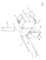
- a condensing unit for mounting on a water heating boiler 2 for forming part of a heating system of which only a system water feed pipe 4 and a system water return pipe 5 are illustrated.
- a burner 6 mounted on the boiler 2.
- the boiler 2 has a boiler system water outlet 7 and a boiler system water return inlet 8.
- the boiler 2 has a boiler gas outlet 9 for connection to an exhaust gas flue 10 having an exhaust gas flue inlet 11 when the condensing unit 1 is not fitted.
- the boiler 2 connects directly to the system water return pipe 5.
- the condensing unit further comprises a main enclosure 12.
- a water jacket inlet 15 is provided in the condensing unit 1, which water jacket inlet 15 is in use connected to the system water return pipe 5.
- the condensing unit 1 also has a water jacket outlet 16 for connection to the boiler system water return inlet 8 and also includes a condensate drain-off 17. Further, the condensing unit 1 has a gas passageway inlet 18 for connection to the boiler gas outlet 9 and a passageway outlet 19 for connection to the exhaust gas flue inlet 11.
- Various connections between the parts are shown by interrupted lines and arrows.
- an exhaust gas flue passageway comprising a main manifold 21 separated by a divider plate 22 into an inlet manifold 25 and an outlet manifold 26.
- the exhaust gas flue passageway 20 further comprises a gas conduit, indicated generally by the reference numeral 30, connecting the inlet manifold 25 to the transfer manifold 27 and then the transfer manifold 27 to the outlet manifold 26.
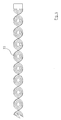
- the gas conduit 30 comprises through tubes 32, each relatively loosely mounting a baffle assembly 33 formed from a spirally wound plate, as illustrated in Fig. 4.
- a water jacket 35 surrounds the gas conduit 30 and further comprises a divider plate 36.
- connection are made, as shown in Fig. 1, and the system water return pipe 5 delivers return water from the heating system into the water jacket inlet 15 and then out through the water jacket outlet 16 to the boiler water return inlet 8.
- the passageway inlet 18 is connected to the boiler gas outlet 9 and the passageway outlet 19 is connected to the exhaust gas flue inlet 11.
- the exhaust gases are delivered through the gas passageway inlet 18 down through the gas conduits 30, namely the tubes 32, from the inlet manifold 25 down to the transfer manifold 27 and then up through further gas conduits 30 into the outlet manifold 26 and from the outlet manifold 26 through the passageway outlet 19 and the gas flue inlet 11 into the flue 10.
- the exhaust gases will heat the system return water so that the water is pre-heated in the boiler. Any condensate bleeds off through the condensate drain off 17.
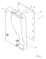
- FIG. 5 there is illustrated an alternative construction of condensing unit, again indicated generally by the reference numeral 1, in which all the parts are similar to those described with reference to the previous drawings, except that in this embodiment, the condensing unit 1 may be mounted on top of a boiler and thus the passageway inlet 18 is connected by a gas transfer duct 40 to the boiler 2.
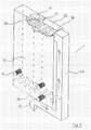
- the water jacket again identified generally by the reference numeral 35, comprises a main tank 41 having substantially parallel extension tanks 42 projecting therefrom and abutting against a cover plate 45.
- the cover plate 45 and the extension tanks 42 form a plurality of gas conduits, again identified by the reference numeral 30.
- This condensing unit 1 may be mounted, as in either of the previous embodiments, namely, against the side of a boiler or on top of the boiler. It will also be appreciated that, for convenience, the condensing unit may be placed spaced-apart from the boiler but should not generally be too far away from it and again, parts similar to those described with reference to the previous drawings, are identified by the same reference numerals.
- FIG. 9 there is illustrated an alternative construction of condensing unit, again indicated generally by the reference numeral 1, which is substantially similar in construction to the condensing unit of Figs. 6 to 8 inclusive, except in this embodiment, the boiler 2 is provided with a cover 50 over its boiler gas outlet (not shown), which cover 50 is effectively divided into two exhaust manifolds 51 and 52, with the manifold 51 having an exhaust outlet 53 for connection to the exhaust gas flue inlet 11.
- the plate 45 is formed from an insulation material having a hole forming a transfer passageway 55 between the exhaust manifold 52 and the inlet manifold 25 and a further transfer passageway 56 between the outlet manifold 26 and the exhaust manifold 52.
- the gas conduit 30 is provided with a sheet of metal 60 bent around its ends.
- the divider plate 22 projects down from the main manifold 21 into the gas flue passageway to divide it into the required gas conduits 30.
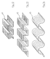
- the gas conduits 30 are essentially provided by what is a central core from which radiates a plurality of outwardly directed hollow fins of substantially triangular cross section. It is manufactured from a sheet of metal 61, as illustrated in Fig. 12. The sheet of metal 61 is simply bent around on itself and is welded along contiguous edges.
- Figs. 13 and 14 there is illustrated other constructions of sheet 62 and 63 for the provision of the gas conduits 30. It will be appreciated that many shapes of bent plate may be used to form the wall 51 of the gas passageway such as the sheets 62 and 63, as illustrated in Figs. 13 and 14. Essentially, the construction is that a considerable contact area is provided, without any need for elaborate welding or other fabrication techniques.
Landscapes
- Engineering & Computer Science (AREA)
- Physics & Mathematics (AREA)
- Thermal Sciences (AREA)
- Mechanical Engineering (AREA)
- General Engineering & Computer Science (AREA)
- Chemical & Material Sciences (AREA)
- Combustion & Propulsion (AREA)
- Geometry (AREA)
- Heat-Exchange Devices With Radiators And Conduit Assemblies (AREA)
- Chimneys And Flues (AREA)
- Heat-Pump Type And Storage Water Heaters (AREA)
Abstract
Description
- The present invention relates to a condensing unit for water heating boilers.
- Such a condensing unit is often used for connection to a water heating boiler in a water heating system, the boiler having a boiler system water outlet and a boiler system water return inlet for connection respectively to a system boiler feed pipe and a system water return pipe and a boiler gas outlet for connection to an exhaust gas flue inlet, the condensing unit comprising an exhaust flue passageway for connection between the boiler gas outlet and the exhaust gas flue inlet, a water jacket surrounding most of the exhaust flue passageway for heat transfer between the water jacket having a water jacket inlet for connection to the system boiler return pipe and a water jacket outlet for connection to the boiler system return inlet. Essentially, the condensing unit acts as a pre-heater for the boiler input water, namely, the system return water.
- However, under certain conditions, when the system water feeding the condensing unit is at a relatively low temperature, the exhaust gases will be cooled below the dew point of certain of the components of the exhaust gases. These components will then condense giving up the latent heat of condensation. Accordingly, under these conditions, the actual efficiency of the boiler could exceed a nominal 100%, that is to say, the actual heat input of the burning fuel such as oil or gas, will exceed the theoretically possible heat exchange between the burning fuel and the system water. The additional heat is provided by the condensing of components of the exhaust gases.
- Generally, the water entering the condenser or condensing unit is of the order of 30°C and the water outlet, having been heated by the flue gases, is of the order of 50°C. The flue gases which originally enter the condensing unit at approximately 180°C are cooled to approximately 45°C and thus condensation occurs. However, if the water entering the condensing unit is at approximately 55°C, it would tend to be delivered out of the condensing unit and into the boiler, that is, very often, the boiler return pipe, at 75°C. Then, the flue gases will usually be of the order of 190°C dropping to 65°C without condensation.
- The main problem with the use of such condensing units, either in conjunction with the boiler as an add-on attachment or integrally mounted within the boiler, is the need to achieve efficient heat transfer while, at the same time, providing a relatively easily maintained unit.
- There are considerable advantages in providing a stand alone add-on unit, in that such an add-on unit or add-on attachment allows it to be used in conjunction with previously fitted boilers. Further, and even more importantly, it can be mounted beside the boiler and thus takes up relatively little space, which can often be a consideration, particularly where boilers are mounted under worktops in kitchens and such areas.
- The present invention is directed towards providing a condensing unit that will achieve some of these aims.
- According to the invention, there is provided a condensing unit for connection to a water heating boiler in a water heating system, the boiler having a boiler system water outlet and a boiler system water return inlet for connection respectively to a system boiler feed pipe and a system water return pipe and a boiler gas outlet for connection to an exhaust gas flue inlet, the condensing unit comprising an exhaust flue passageway for connection between the boiler gas outlet and the exhaust gas flue inlet, a water jacket surrounding most of the exhaust flue passageway for heat transfer between the water jacket having a water jacket inlet for connection to the system boiler return pipe and a water jacket outlet for connection to the boiler system return inlet, characterised in that the condensing unit comprises:
- a freestanding main enclosure; and
- the exhaust gas flue passageway comprises a pair of spaced-apart manifolds,
- namely, a main manifold divided into an inlet manifold having a passageway inlet for connection to the boiler gas outlet and an outlet manifold having a passageway outlet for connection to the exhaust gas flue inlet and a transfer manifold and at least one gas transfer conduit between each of the inlet and outlet manifolds and the transfer manifold.
- There are major advantages with this construction. By having a freestanding unit, it is possible to mount the unit in conjunction with existing boilers and thus ensure that the heating efficiency of existing boilers is greatly enhanced. Heretofore, such units were always incorporated within the boiler and thus to provide a condensing unit essentially required the provision of a new boiler. Further, the particular construction allows easy cleaning and an efficient heat transfer because the flue gases are led back and forth across the condensing unit, greatly enhancing heat transfer. The whole purpose is to cool the exhaust gases from the boiler as much as possible so that condensation will occur. This particular construction allows such cooling. The more heat that could be extracted from the flue gases, the better.
- ln one embodiment of the invention, each gas conduit comprises a through tube mounting a baffle assembly, which baffle assembly may comprise a spirally wound plate. Ideally, there are a plurality of tubes between each of the manifolds. This particular construction of baffle assembly is relatively efficient to clean, efficient to manufacture and gives amazingly good heat transfer.
- In another embodiment of the invention, the water jacket surrounds all the gas conduits.
- ln another embodiment of the invention, each gas conduit comprises a tubular member having a peripheral wall forming, in cross section, peaks and valleys whereby additional contact area separating the water and exhaust gases is provided.
- In a still further embodiment, there are two gas conduits formed by the one tubular member with a dividing wall forming the separate gas conduits, the tubular member having a peripheral wall forming, in cross section, peaks and valleys whereby additional contact area separating the water and exhaust gases is provided. The great advantage of this particular construction is that the gas conduit may be provided by a sheet of metal bent around its ends and welded along contiguous edges. This is a very simple construction of unit to provide. It is easy to manufacture and relatively in expensive. A very efficient heat transfer surface is achieved with relatively little difficulty. Further, because it is manufactured from the one sheet, leaks, etc. are unlikely to occur. It also reduces the amount of welding and consequently, welding inspection, required.
- In another embodiment of the invention, the water jacket comprises a main tank having substantially parallel extension tanks projecting therefrom and abutting against a cover plate, the cover plate extension tanks and the main tank forming the plurality gas conduits therebetween. The cover plate can also be in the form of another water tank communicating with the main tank. Again, this is a relatively simple construction and particularly when the cover plate is simply a plain cover plate, it can be easily removed for cleaning.
- In a still further embodiment of the invention, the water jacket comprises an internal partial divider wall dividing the water jacket into two separate tanks interconnected adjacent the transfer manifold, one tank in contact with the gas transfer conduit between the inlet end transfer manifolds, the other with the gas transfer conduit between the outlet and transfer manifolds.
- Ideally, the main enclosure is adapted to lie against the side of the boiler in close proximity thereto or on top of the boiler.
- The invention will be more clearly understood from the following description of some embodiments thereof, given by way of example only, with reference to, the accompanying drawings, in which:
- Fig. 1 is a schematic exploded view of a condensing unit fitted in a heating system,
- Fig. 2 is a perspective partially cut-away view of the condensing unit of Fig. 1,
- Fig. 3 is a typical diagrammatic section through the condensing unit,
- Fig. 4 is a perspective view of a baffle used in the condensing unit,
- Fig. 5 is a perspective partially cut-away view of another condensing unit according to the invention,
- Fig. 6 is a perspective view of a still further condensing unit according to the invention,
- Fig. 7 is a plan sectional view of the condensing unit of Fig. 5,
- Fig. 8 is a typical vertical sectional view of the condensing unit of Fig. 6,
- Fig. 9 is a perspective view of an alternative construction of condensing unit affixed to a boiler,
- Fig. 10 is a plan partially diagrammatic view of another condensing unit according to the invention,
- Fig. 11 is a sectional diagrammatic view of the condensing unit of Fig. 10,
- Fig. 12 is a perspective view of portion of a metal sheet used in the construction of the condensing unit of Figs. 10 and 11, and
- Figs. 13 and 14 are views of different sheets that could be used in the construction of the condensing unit of Figs. 10 and 11.
- Referring to the drawings and initially to Figs. 1 to 4 thereof, there is provided a condensing unit, indicated generally by the
reference numeral 1, for mounting on awater heating boiler 2 for forming part of a heating system of which only a systemwater feed pipe 4 and a system water return pipe 5 are illustrated. There is also illustrated aburner 6 mounted on theboiler 2. Theboiler 2 has a boiler system water outlet 7 and a boiler systemwater return inlet 8. Theboiler 2 has aboiler gas outlet 9 for connection to anexhaust gas flue 10 having an exhaust gas flue inlet 11 when thecondensing unit 1 is not fitted. Similarly, when the condensing unit is not fitted, theboiler 2 connects directly to the system water return pipe 5. The condensing unit further comprises amain enclosure 12. - A
water jacket inlet 15 is provided in thecondensing unit 1, whichwater jacket inlet 15 is in use connected to the system water return pipe 5. The condensingunit 1 also has awater jacket outlet 16 for connection to the boiler systemwater return inlet 8 and also includes a condensate drain-off 17. Further, the condensingunit 1 has agas passageway inlet 18 for connection to theboiler gas outlet 9 and apassageway outlet 19 for connection to the exhaust gas flue inlet 11. Various connections between the parts are shown by interrupted lines and arrows. - Referring now to Figs. 2 and 3, there is illustrated an exhaust gas flue passageway, indicated generally by the
reference numeral 20, comprising amain manifold 21 separated by adivider plate 22 into aninlet manifold 25 and anoutlet manifold 26. The exhaustgas flue passageway 20 further comprises a gas conduit, indicated generally by thereference numeral 30, connecting theinlet manifold 25 to thetransfer manifold 27 and then thetransfer manifold 27 to theoutlet manifold 26. In this embodiment, thegas conduit 30 comprises throughtubes 32, each relatively loosely mounting abaffle assembly 33 formed from a spirally wound plate, as illustrated in Fig. 4. Awater jacket 35 surrounds thegas conduit 30 and further comprises adivider plate 36. - In use, connections are made, as shown in Fig. 1, and the system water return pipe 5 delivers return water from the heating system into the
water jacket inlet 15 and then out through thewater jacket outlet 16 to the boilerwater return inlet 8. Thepassageway inlet 18 is connected to theboiler gas outlet 9 and thepassageway outlet 19 is connected to the exhaust gas flue inlet 11. - Thus, in operation of the
boiler 2, the exhaust gases are delivered through thegas passageway inlet 18 down through thegas conduits 30, namely thetubes 32, from theinlet manifold 25 down to thetransfer manifold 27 and then up throughfurther gas conduits 30 into theoutlet manifold 26 and from theoutlet manifold 26 through thepassageway outlet 19 and the gas flue inlet 11 into theflue 10. Thus, the exhaust gases will heat the system return water so that the water is pre-heated in the boiler. Any condensate bleeds off through the condensate drain off 17. - Referring to Fig. 5, there is illustrated an alternative construction of condensing unit, again indicated generally by the
reference numeral 1, in which all the parts are similar to those described with reference to the previous drawings, except that in this embodiment, the condensingunit 1 may be mounted on top of a boiler and thus thepassageway inlet 18 is connected by agas transfer duct 40 to theboiler 2. - Referring to Figs. 6 to 8 inclusive, there is illustrated an alternative construction of condensing unit, again indicated generally by the
reference numeral 1 and parts similar to those described with reference to the previous drawings, are identified by the same reference numerals. In this embodiment, the water jacket, again identified generally by thereference numeral 35, comprises amain tank 41 having substantiallyparallel extension tanks 42 projecting therefrom and abutting against acover plate 45. Thecover plate 45 and theextension tanks 42 form a plurality of gas conduits, again identified by thereference numeral 30. This condensingunit 1 may be mounted, as in either of the previous embodiments, namely, against the side of a boiler or on top of the boiler. It will also be appreciated that, for convenience, the condensing unit may be placed spaced-apart from the boiler but should not generally be too far away from it and again, parts similar to those described with reference to the previous drawings, are identified by the same reference numerals. - Referring to Fig. 9, there is illustrated an alternative construction of condensing unit, again indicated generally by the
reference numeral 1, which is substantially similar in construction to the condensing unit of Figs. 6 to 8 inclusive, except in this embodiment, theboiler 2 is provided with acover 50 over its boiler gas outlet (not shown), which cover 50 is effectively divided into twoexhaust manifolds exhaust outlet 53 for connection to the exhaust gas flue inlet 11. In this embodiment, theplate 45 is formed from an insulation material having a hole forming atransfer passageway 55 between theexhaust manifold 52 and theinlet manifold 25 and afurther transfer passageway 56 between theoutlet manifold 26 and theexhaust manifold 52. - Referring to Figs. 10 to 13, there is illustrated a further construction of condensing unit, again indicated generally by the
reference numeral 1, in which parts similar to those described with reference to the previous drawings, are identified by the same reference numerals. ln this embodiment, thegas conduit 30 is provided with a sheet ofmetal 60 bent around its ends. Thedivider plate 22 projects down from themain manifold 21 into the gas flue passageway to divide it into the requiredgas conduits 30. Thegas conduits 30 are essentially provided by what is a central core from which radiates a plurality of outwardly directed hollow fins of substantially triangular cross section. It is manufactured from a sheet ofmetal 61, as illustrated in Fig. 12. The sheet ofmetal 61 is simply bent around on itself and is welded along contiguous edges. - Referring to Figs. 13 and 14, there is illustrated other constructions of
sheet gas conduits 30. It will be appreciated that many shapes of bent plate may be used to form thewall 51 of the gas passageway such as thesheets - In the specification the terms "comprise, comprises, comprised and comprising" or any variation thereof and the terms "include, includes, included and including" or any variation thereof are considered to be totally interchangeable and they should all be afforded the widest possible interpretation and vice versa.
- The invention is not limited to the embodiment hereinbefore described, but may be varied in both construction and detail within the scope of the claims.
Claims (6)
- A condensing unit (1) for connection to a water heating boiler (2) in a water heating system, the boiler (2) having a boiler system water outlet (7) and a boiler system water return inlet (8) for connection respectively to a system boiler feed pipe (4) and a system water return pipe (5) and a boiler gas outlet (9) for connection to an exhaust gas flue inlet (11), the condensing unit (1) comprising an exhaust flue passageway (20) for connection between the boiler gas outlet (9) and the exhaust gas flue inlet (11), a water jacket (35) surrounding most of the exhaust flue passageway (20) for heat transfer between the water jacket (35) having a water jacket inlet (15) for connection to the system boiler return pipe (5) and a water jacket outlet (16) for connection to the boiler system return inlet (18), characterised in that the condensing unit (1) comprises:a freestanding main enclosure (12);the exhaust gas flue passageway (20) comprises a pair of spaced-apart manifolds (21, 27), namely, a main manifold (21) divided into an inlet manifold (25) having a passageway inlet (19) for connection to the boiler gas outlet (9) and an outlet manifold (26) having a passageway outlet (19) for connection to the exhaust gas flue inlet (11) and a transfer manifold (27) and at least one gas transfer conduit (30) between each of the inlet and outlet manifolds (25, 26) and the transfer manifold (27); andin which the water jacket (35) comprises a main tank (41) having substantially parallel extension tanks (42) projecting therefrom and abutting against a cover plate (45), the cover plate (45) extension tanks (42) and the main tank (4) forming the plurality gas conduits (30) therebetween.
- A condensing unit (1) as claimed in claim 1, in which the cover plate (45) is in the form of another water tank communicating with the main tank.
- A condensing unit (1) as claimed in claim 1 or 2, in which the water jacket (35) comprises an internal partial divider wall (36) dividing the water jacket (35) into two separate tanks interconnected adjacent the transfer manifold (27), one tank in contact with the gas transfer conduit (30) between the inlet end transfer manifolds (25, 27), the other with the gas transfer conduit between the outlet and transfer manifolds (27, 26).
- A condensing unit (1) as claimed in any preceding claim in which the main enclosure (12) is adapted to lie against the side of the boiler (2) in close proximity thereto.
- A condensing unit (1) as claimed in any of claims 1 to 3, in which the main enclosure (12) is adapted to lie on top of the boiler (2).
- A condensing unit (1) as claimed in claim 1, in which the boiler (2) is provided with a cover (50) over the boiler gas outlet (9) which is divided into two exhaust gas manifolds (51 and 52) with one manifold (51) having an exhaust outlet (53) for connection to the exhaust gas flue inlet (11) and wherein the coverplate (45) is formed from an insulation material having a hole forming a transfer passageway (55) between the exhaust manifold (52) and an inlet manifold (25) and a further transfer passageway (56) between the outlet manifold and the exhaust manifold.
Applications Claiming Priority (3)
| Application Number | Priority Date | Filing Date | Title |
|---|---|---|---|
| IE20030347 | 2003-05-08 | ||
| IE20030573 | 2003-07-31 | ||
| EP04394025A EP1475579A3 (en) | 2003-05-08 | 2004-05-10 | A condensing unit |
Related Parent Applications (1)
| Application Number | Title | Priority Date | Filing Date |
|---|---|---|---|
| EP04394025A Division EP1475579A3 (en) | 2003-05-08 | 2004-05-10 | A condensing unit |
Publications (3)
| Publication Number | Publication Date |
|---|---|
| EP1813884A2 true EP1813884A2 (en) | 2007-08-01 |
| EP1813884A3 EP1813884A3 (en) | 2007-10-24 |
| EP1813884B1 EP1813884B1 (en) | 2017-02-22 |
Family
ID=32992642
Family Applications (2)
| Application Number | Title | Priority Date | Filing Date |
|---|---|---|---|
| EP04394025A Ceased EP1475579A3 (en) | 2003-05-08 | 2004-05-10 | A condensing unit |
| EP07107173.2A Expired - Lifetime EP1813884B1 (en) | 2003-05-08 | 2004-05-10 | A condensing unit |
Family Applications Before (1)
| Application Number | Title | Priority Date | Filing Date |
|---|---|---|---|
| EP04394025A Ceased EP1475579A3 (en) | 2003-05-08 | 2004-05-10 | A condensing unit |
Country Status (2)
| Country | Link |
|---|---|
| EP (2) | EP1475579A3 (en) |
| IE (2) | IES20040324A2 (en) |
Cited By (2)
| Publication number | Priority date | Publication date | Assignee | Title |
|---|---|---|---|---|
| GB2408565B (en) * | 2003-11-28 | 2008-12-03 | Worcester Heat Systems Ltd | Secondary heat exchanger |
| CN105091338A (en) * | 2014-05-08 | 2015-11-25 | 李明明 | Horizontal condensation type briquette coal heating stove |
Families Citing this family (9)
| Publication number | Priority date | Publication date | Assignee | Title |
|---|---|---|---|---|
| DE502005008317D1 (en) | 2005-03-09 | 2009-11-26 | Gea Ecoflex Gmbh | Method for heat energy transfer |
| CN101586920B (en) * | 2009-06-22 | 2011-05-11 | 中山华帝燃具股份有限公司 | Shell and tube heat exchanger |
| DE102012207305A1 (en) | 2012-05-02 | 2013-11-07 | Webasto Ag | A heater for a vehicle and method of operating the heater |
| BE1023641B1 (en) * | 2015-11-23 | 2017-05-30 | Atlas Copco Airpower, Naamloze Vennootschap | HEAT EXCHANGER AND METHOD FOR SEPARATING A LIQUID FROM A GAS |
| CN106642692B (en) * | 2016-07-28 | 2022-08-19 | 艾欧史密斯(中国)热水器有限公司 | Condensation gas water heater and condensation heat exchanger |
| CN109990614A (en) * | 2019-04-26 | 2019-07-09 | 平顶山市百阳丰机械制造有限公司 | A kind of Water cooling jacket type condenser |
| CN111536543B (en) * | 2020-05-13 | 2022-06-07 | 哈电发电设备国家工程研究中心有限公司 | Flue gas cooler applied to mobile medical waste treatment system |
| CN114087786A (en) * | 2021-10-29 | 2022-02-25 | 江柴发动机徐州有限公司 | Horizontal condensation integrated normal-pressure hot water boiler and working method |
| US12508522B2 (en) | 2022-09-15 | 2025-12-30 | Modine Manufacturing Company | Deaeration tank |
Family Cites Families (8)
| Publication number | Priority date | Publication date | Assignee | Title |
|---|---|---|---|---|
| CH613512A5 (en) * | 1976-07-30 | 1979-09-28 | Sulzer Ag | |
| DE3778660D1 (en) * | 1986-12-06 | 1992-06-04 | Vaillant Joh Gmbh & Co | STEEL BOILER. |
| GB2304399A (en) * | 1995-08-15 | 1997-03-19 | Nicholas John Critchley | Condensing boiler heat exchanger |
| GB9806306D0 (en) * | 1998-03-25 | 1998-05-20 | Ravenheat Manufacturing Ltd | Heating appliance |
| DE19826094A1 (en) * | 1998-06-12 | 1999-12-23 | Viessmann Werke Kg | boiler |
| GB2373841B (en) * | 2001-03-30 | 2003-05-07 | Aquaflame Ltd | Heat exchanger for fossil fuel fired boiler |
| EP1267134B1 (en) * | 2001-06-11 | 2012-04-11 | Alley Enterprises Limited | A condensing boiler |
| GB2408565B (en) * | 2003-11-28 | 2008-12-03 | Worcester Heat Systems Ltd | Secondary heat exchanger |
-
2004
- 2004-05-10 IE IE20040324A patent/IES20040324A2/en not_active IP Right Cessation
- 2004-05-10 IE IE20040322A patent/IE20040322A1/en unknown
- 2004-05-10 EP EP04394025A patent/EP1475579A3/en not_active Ceased
- 2004-05-10 EP EP07107173.2A patent/EP1813884B1/en not_active Expired - Lifetime
Cited By (2)
| Publication number | Priority date | Publication date | Assignee | Title |
|---|---|---|---|---|
| GB2408565B (en) * | 2003-11-28 | 2008-12-03 | Worcester Heat Systems Ltd | Secondary heat exchanger |
| CN105091338A (en) * | 2014-05-08 | 2015-11-25 | 李明明 | Horizontal condensation type briquette coal heating stove |
Also Published As
| Publication number | Publication date |
|---|---|
| IE20040322A1 (en) | 2004-11-17 |
| EP1475579A3 (en) | 2005-04-20 |
| IES20040324A2 (en) | 2004-11-17 |
| EP1813884A3 (en) | 2007-10-24 |
| EP1475579A2 (en) | 2004-11-10 |
| EP1813884B1 (en) | 2017-02-22 |
Similar Documents
| Publication | Publication Date | Title |
|---|---|---|
| US8056553B2 (en) | Condensate pan with condensate trap | |
| CA2128471C (en) | Heat exchanger | |
| US8393318B2 (en) | Heat exchanger | |
| CN100451526C (en) | Universal heat exchanger for boiler and hot water supply system | |
| JP3882024B2 (en) | Heat exchanger with double tube bundle | |
| GB2025586A (en) | Heating and domestic hot water boiler apparatus | |
| US4730600A (en) | Condensing furnace | |
| EP1813884A2 (en) | A condensing unit | |
| NZ270455A (en) | Heat exchanger assembly; recuperative type used in condensing furnaces and having a dual drainage slope secondary heat exchange section | |
| US4448136A (en) | Boiler with waste heat recovery | |
| CN101395433B (en) | Single tank combined heat source machine | |
| EP1243866A1 (en) | Heat exchanger in a condensation boiler | |
| EP1750070A1 (en) | Heat exchanger with finned tube and method of producing the same | |
| US4779676A (en) | Condensing furnace | |
| EP1600708A1 (en) | Method of producing a gas boiler, and gas boiler so produced | |
| EP1821046B1 (en) | A condensing boiler | |
| EP0461781B1 (en) | Heat exchanger | |
| US9631877B2 (en) | Furnace heat exchanger coupling | |
| IE20040324U1 (en) | A condensing unit | |
| IES83697Y1 (en) | A condensing unit | |
| GB2049126A (en) | Boiler | |
| GB2103351A (en) | Flue arrangements for boilers | |
| JP4728056B2 (en) | Hot water equipment | |
| RU2721496C2 (en) | Water heater, gas combustion gases discharge pipe for water heater and method of fluid medium heating | |
| IE20020469A1 (en) | A condensing boiler |
Legal Events
| Date | Code | Title | Description |
|---|---|---|---|
| PUAI | Public reference made under article 153(3) epc to a published international application that has entered the european phase |
Free format text: ORIGINAL CODE: 0009012 |
|
| AC | Divisional application: reference to earlier application |
Ref document number: 1475579 Country of ref document: EP Kind code of ref document: P |
|
| AK | Designated contracting states |
Kind code of ref document: A2 Designated state(s): AT BE BG CH CY CZ DE DK EE ES FI FR GB GR HU IE IT LI LU MC NL PL PT RO SE SI SK TR |
|
| PUAL | Search report despatched |
Free format text: ORIGINAL CODE: 0009013 |
|
| AK | Designated contracting states |
Kind code of ref document: A3 Designated state(s): AT BE BG CH CY CZ DE DK EE ES FI FR GB GR HU IE IT LI LU MC NL PL PT RO SE SI SK TR |
|
| 17P | Request for examination filed |
Effective date: 20070427 |
|
| AKX | Designation fees paid |
Designated state(s): AT BE BG CH CY CZ DE DK EE ES FI FR GB GR HU IE IT LI LU MC NL PL PT RO SE SI SK TR |
|
| 17Q | First examination report despatched |
Effective date: 20140714 |
|
| REG | Reference to a national code |
Ref country code: DE Ref legal event code: R079 Ref document number: 602004050804 Country of ref document: DE Free format text: PREVIOUS MAIN CLASS: F24H0008000000 Ipc: F28F0013120000 |
|
| GRAP | Despatch of communication of intention to grant a patent |
Free format text: ORIGINAL CODE: EPIDOSNIGR1 |
|
| RIC1 | Information provided on ipc code assigned before grant |
Ipc: F28D 7/16 20060101ALI20160601BHEP Ipc: F28D 9/00 20060101ALI20160601BHEP Ipc: F24H 8/00 20060101ALI20160601BHEP Ipc: F28D 21/00 20060101ALI20160601BHEP Ipc: F28F 13/12 20060101AFI20160601BHEP Ipc: F28F 3/12 20060101ALI20160601BHEP |
|
| INTG | Intention to grant announced |
Effective date: 20160704 |
|
| GRAS | Grant fee paid |
Free format text: ORIGINAL CODE: EPIDOSNIGR3 |
|
| STAA | Information on the status of an ep patent application or granted ep patent |
Free format text: STATUS: GRANT OF PATENT IS INTENDED |
|
| GRAJ | Information related to disapproval of communication of intention to grant by the applicant or resumption of examination proceedings by the epo deleted |
Free format text: ORIGINAL CODE: EPIDOSDIGR1 |
|
| GRAL | Information related to payment of fee for publishing/printing deleted |
Free format text: ORIGINAL CODE: EPIDOSDIGR3 |
|
| STAA | Information on the status of an ep patent application or granted ep patent |
Free format text: STATUS: EXAMINATION IS IN PROGRESS |
|
| GRAP | Despatch of communication of intention to grant a patent |
Free format text: ORIGINAL CODE: EPIDOSNIGR1 |
|
| STAA | Information on the status of an ep patent application or granted ep patent |
Free format text: STATUS: GRANT OF PATENT IS INTENDED |
|
| INTC | Intention to grant announced (deleted) | ||
| INTG | Intention to grant announced |
Effective date: 20161216 |
|
| GRAA | (expected) grant |
Free format text: ORIGINAL CODE: 0009210 |
|
| STAA | Information on the status of an ep patent application or granted ep patent |
Free format text: STATUS: THE PATENT HAS BEEN GRANTED |
|
| AC | Divisional application: reference to earlier application |
Ref document number: 1475579 Country of ref document: EP Kind code of ref document: P |
|
| AK | Designated contracting states |
Kind code of ref document: B1 Designated state(s): AT BE BG CH CY CZ DE DK EE ES FI FR GB GR HU IE IT LI LU MC NL PL PT RO SE SI SK TR |
|
| REG | Reference to a national code |
Ref country code: GB Ref legal event code: FG4D |
|
| REG | Reference to a national code |
Ref country code: CH Ref legal event code: EP |
|
| REG | Reference to a national code |
Ref country code: AT Ref legal event code: REF Ref document number: 869580 Country of ref document: AT Kind code of ref document: T Effective date: 20170315 |
|
| REG | Reference to a national code |
Ref country code: IE Ref legal event code: FG4D |
|
| REG | Reference to a national code |
Ref country code: DE Ref legal event code: R096 Ref document number: 602004050804 Country of ref document: DE |
|
| REG | Reference to a national code |
Ref country code: NL Ref legal event code: MP Effective date: 20170222 |
|
| REG | Reference to a national code |
Ref country code: AT Ref legal event code: MK05 Ref document number: 869580 Country of ref document: AT Kind code of ref document: T Effective date: 20170222 |
|
| PG25 | Lapsed in a contracting state [announced via postgrant information from national office to epo] |
Ref country code: GR Free format text: LAPSE BECAUSE OF FAILURE TO SUBMIT A TRANSLATION OF THE DESCRIPTION OR TO PAY THE FEE WITHIN THE PRESCRIBED TIME-LIMIT Effective date: 20170523 Ref country code: FI Free format text: LAPSE BECAUSE OF FAILURE TO SUBMIT A TRANSLATION OF THE DESCRIPTION OR TO PAY THE FEE WITHIN THE PRESCRIBED TIME-LIMIT Effective date: 20170222 |
|
| PG25 | Lapsed in a contracting state [announced via postgrant information from national office to epo] |
Ref country code: SE Free format text: LAPSE BECAUSE OF FAILURE TO SUBMIT A TRANSLATION OF THE DESCRIPTION OR TO PAY THE FEE WITHIN THE PRESCRIBED TIME-LIMIT Effective date: 20170222 Ref country code: LU Free format text: LAPSE BECAUSE OF NON-PAYMENT OF DUE FEES Effective date: 20170531 Ref country code: NL Free format text: LAPSE BECAUSE OF FAILURE TO SUBMIT A TRANSLATION OF THE DESCRIPTION OR TO PAY THE FEE WITHIN THE PRESCRIBED TIME-LIMIT Effective date: 20170222 Ref country code: AT Free format text: LAPSE BECAUSE OF FAILURE TO SUBMIT A TRANSLATION OF THE DESCRIPTION OR TO PAY THE FEE WITHIN THE PRESCRIBED TIME-LIMIT Effective date: 20170222 Ref country code: PT Free format text: LAPSE BECAUSE OF FAILURE TO SUBMIT A TRANSLATION OF THE DESCRIPTION OR TO PAY THE FEE WITHIN THE PRESCRIBED TIME-LIMIT Effective date: 20170622 Ref country code: ES Free format text: LAPSE BECAUSE OF FAILURE TO SUBMIT A TRANSLATION OF THE DESCRIPTION OR TO PAY THE FEE WITHIN THE PRESCRIBED TIME-LIMIT Effective date: 20170222 Ref country code: BG Free format text: LAPSE BECAUSE OF FAILURE TO SUBMIT A TRANSLATION OF THE DESCRIPTION OR TO PAY THE FEE WITHIN THE PRESCRIBED TIME-LIMIT Effective date: 20170522 |
|
| PG25 | Lapsed in a contracting state [announced via postgrant information from national office to epo] |
Ref country code: SK Free format text: LAPSE BECAUSE OF FAILURE TO SUBMIT A TRANSLATION OF THE DESCRIPTION OR TO PAY THE FEE WITHIN THE PRESCRIBED TIME-LIMIT Effective date: 20170222 Ref country code: RO Free format text: LAPSE BECAUSE OF FAILURE TO SUBMIT A TRANSLATION OF THE DESCRIPTION OR TO PAY THE FEE WITHIN THE PRESCRIBED TIME-LIMIT Effective date: 20170222 Ref country code: CZ Free format text: LAPSE BECAUSE OF FAILURE TO SUBMIT A TRANSLATION OF THE DESCRIPTION OR TO PAY THE FEE WITHIN THE PRESCRIBED TIME-LIMIT Effective date: 20170222 Ref country code: IT Free format text: LAPSE BECAUSE OF FAILURE TO SUBMIT A TRANSLATION OF THE DESCRIPTION OR TO PAY THE FEE WITHIN THE PRESCRIBED TIME-LIMIT Effective date: 20170222 Ref country code: EE Free format text: LAPSE BECAUSE OF FAILURE TO SUBMIT A TRANSLATION OF THE DESCRIPTION OR TO PAY THE FEE WITHIN THE PRESCRIBED TIME-LIMIT Effective date: 20170222 |
|
| REG | Reference to a national code |
Ref country code: DE Ref legal event code: R097 Ref document number: 602004050804 Country of ref document: DE |
|
| PG25 | Lapsed in a contracting state [announced via postgrant information from national office to epo] |
Ref country code: DK Free format text: LAPSE BECAUSE OF FAILURE TO SUBMIT A TRANSLATION OF THE DESCRIPTION OR TO PAY THE FEE WITHIN THE PRESCRIBED TIME-LIMIT Effective date: 20170222 Ref country code: PL Free format text: LAPSE BECAUSE OF FAILURE TO SUBMIT A TRANSLATION OF THE DESCRIPTION OR TO PAY THE FEE WITHIN THE PRESCRIBED TIME-LIMIT Effective date: 20170222 |
|
| REG | Reference to a national code |
Ref country code: DE Ref legal event code: R119 Ref document number: 602004050804 Country of ref document: DE |
|
| PLBE | No opposition filed within time limit |
Free format text: ORIGINAL CODE: 0009261 |
|
| REG | Reference to a national code |
Ref country code: CH Ref legal event code: PL |
|
| STAA | Information on the status of an ep patent application or granted ep patent |
Free format text: STATUS: NO OPPOSITION FILED WITHIN TIME LIMIT |
|
| GBPC | Gb: european patent ceased through non-payment of renewal fee |
Effective date: 20170522 |
|
| 26N | No opposition filed |
Effective date: 20171123 |
|
| PG25 | Lapsed in a contracting state [announced via postgrant information from national office to epo] |
Ref country code: MC Free format text: LAPSE BECAUSE OF FAILURE TO SUBMIT A TRANSLATION OF THE DESCRIPTION OR TO PAY THE FEE WITHIN THE PRESCRIBED TIME-LIMIT Effective date: 20170222 |
|
| REG | Reference to a national code |
Ref country code: IE Ref legal event code: MM4A |
|
| PG25 | Lapsed in a contracting state [announced via postgrant information from national office to epo] |
Ref country code: SI Free format text: LAPSE BECAUSE OF FAILURE TO SUBMIT A TRANSLATION OF THE DESCRIPTION OR TO PAY THE FEE WITHIN THE PRESCRIBED TIME-LIMIT Effective date: 20170222 Ref country code: CH Free format text: LAPSE BECAUSE OF NON-PAYMENT OF DUE FEES Effective date: 20170531 Ref country code: LI Free format text: LAPSE BECAUSE OF NON-PAYMENT OF DUE FEES Effective date: 20170531 |
|
| REG | Reference to a national code |
Ref country code: FR Ref legal event code: ST Effective date: 20180131 |
|
| PG25 | Lapsed in a contracting state [announced via postgrant information from national office to epo] |
Ref country code: LU Free format text: LAPSE BECAUSE OF NON-PAYMENT OF DUE FEES Effective date: 20170510 |
|
| REG | Reference to a national code |
Ref country code: BE Ref legal event code: MM Effective date: 20170531 |
|
| PG25 | Lapsed in a contracting state [announced via postgrant information from national office to epo] |
Ref country code: IE Free format text: LAPSE BECAUSE OF NON-PAYMENT OF DUE FEES Effective date: 20170510 Ref country code: GB Free format text: LAPSE BECAUSE OF NON-PAYMENT OF DUE FEES Effective date: 20170522 Ref country code: DE Free format text: LAPSE BECAUSE OF NON-PAYMENT OF DUE FEES Effective date: 20171201 |
|
| PG25 | Lapsed in a contracting state [announced via postgrant information from national office to epo] |
Ref country code: FR Free format text: LAPSE BECAUSE OF NON-PAYMENT OF DUE FEES Effective date: 20170531 |
|
| PG25 | Lapsed in a contracting state [announced via postgrant information from national office to epo] |
Ref country code: BE Free format text: LAPSE BECAUSE OF NON-PAYMENT OF DUE FEES Effective date: 20170531 |
|
| PG25 | Lapsed in a contracting state [announced via postgrant information from national office to epo] |
Ref country code: HU Free format text: LAPSE BECAUSE OF FAILURE TO SUBMIT A TRANSLATION OF THE DESCRIPTION OR TO PAY THE FEE WITHIN THE PRESCRIBED TIME-LIMIT; INVALID AB INITIO Effective date: 20040510 |
|
| PG25 | Lapsed in a contracting state [announced via postgrant information from national office to epo] |
Ref country code: CY Free format text: LAPSE BECAUSE OF NON-PAYMENT OF DUE FEES Effective date: 20170222 |
|
| PG25 | Lapsed in a contracting state [announced via postgrant information from national office to epo] |
Ref country code: TR Free format text: LAPSE BECAUSE OF FAILURE TO SUBMIT A TRANSLATION OF THE DESCRIPTION OR TO PAY THE FEE WITHIN THE PRESCRIBED TIME-LIMIT Effective date: 20170222 |