EP1813836A1 - Wave gear device - Google Patents
Wave gear device Download PDFInfo
- Publication number
- EP1813836A1 EP1813836A1 EP05788212A EP05788212A EP1813836A1 EP 1813836 A1 EP1813836 A1 EP 1813836A1 EP 05788212 A EP05788212 A EP 05788212A EP 05788212 A EP05788212 A EP 05788212A EP 1813836 A1 EP1813836 A1 EP 1813836A1
- Authority
- EP
- European Patent Office
- Prior art keywords
- arc
- external tooth
- gear device
- wave gear
- flex spline
- Prior art date
- Legal status (The legal status is an assumption and is not a legal conclusion. Google has not performed a legal analysis and makes no representation as to the accuracy of the status listed.)
- Withdrawn
Links
Images


Classifications
-
- F—MECHANICAL ENGINEERING; LIGHTING; HEATING; WEAPONS; BLASTING
- F16—ENGINEERING ELEMENTS AND UNITS; GENERAL MEASURES FOR PRODUCING AND MAINTAINING EFFECTIVE FUNCTIONING OF MACHINES OR INSTALLATIONS; THERMAL INSULATION IN GENERAL
- F16H—GEARING
- F16H1/00—Toothed gearings for conveying rotary motion
- F16H1/28—Toothed gearings for conveying rotary motion with gears having orbital motion
- F16H1/32—Toothed gearings for conveying rotary motion with gears having orbital motion in which the central axis of the gearing lies inside the periphery of an orbital gear
-
- F—MECHANICAL ENGINEERING; LIGHTING; HEATING; WEAPONS; BLASTING
- F16—ENGINEERING ELEMENTS AND UNITS; GENERAL MEASURES FOR PRODUCING AND MAINTAINING EFFECTIVE FUNCTIONING OF MACHINES OR INSTALLATIONS; THERMAL INSULATION IN GENERAL
- F16H—GEARING
- F16H49/00—Other gearings
- F16H49/001—Wave gearings, e.g. harmonic drive transmissions
-
- Y—GENERAL TAGGING OF NEW TECHNOLOGICAL DEVELOPMENTS; GENERAL TAGGING OF CROSS-SECTIONAL TECHNOLOGIES SPANNING OVER SEVERAL SECTIONS OF THE IPC; TECHNICAL SUBJECTS COVERED BY FORMER USPC CROSS-REFERENCE ART COLLECTIONS [XRACs] AND DIGESTS
- Y10—TECHNICAL SUBJECTS COVERED BY FORMER USPC
- Y10T—TECHNICAL SUBJECTS COVERED BY FORMER US CLASSIFICATION
- Y10T74/00—Machine element or mechanism
- Y10T74/19—Gearing
Definitions
- the present invention relates to a wave gear device for transmitting a torque.
- Patent Document 1 JP-A-2004-28122 (Pages 3 - 4, Fig. 3)
- the invention has an object to provide a wave gear device capable of transmitting a higher torque than that of the background art.
- a wave gear device comprising: an annular internal tooth gear having internal teeth formed thereon; a flexible external tooth gear including an external tooth portion having external teeth formed to mesh partially with said internal teeth, and arranged on the inner side of said internal tooth gear; and a wave generator arranged on the inner side of said external tooth gear for rotating said external tooth gear while warping the same with respect to said internal tooth gear.
- the wave gear device has such a constitution that said external tooth gear includes a fixed portion adapted to be fixed on an external member, and a connecting portion for connecting said external tooth portion and said fixed portion, and that said connecting portion is so shaped that the sectional shape cut in a plane extending through the axis of rotation of said external tooth gear is gradually reduced in shape toward the substantial center from the side of said external tooth portion and the side of said fixed portion, and that two confronting outer lines on said sectional shape are substantially arcuate.
- the sectional shape, when cut in a plane extending through the axis of rotation of the external tooth gear, of the connecting portion of the external tooth gear is gradually reduced in thickness toward the substantial center from the side of the external tooth portion and the side of the fixed portion.
- the wave gear device is so constituted that at least a portion of one of said two outer lines is a first arc, that at least a portion of the other of said two outer lines is a second arc having a radius and a center position different from those of the first arc, and that said first arc and said second arc form the thinnest portion of the substantial center of said sectional shape.
- the wave gear device is so constituted that at least a portion of one of said two outer lines is a first arc, that at least a portion of the other of said two outer lines is a second arc having a radius and a center position different from those of the first arc, and that said first arc and said second arc are so formed that a straight line smaller than the radius of said first arc and the radius of said second arm and extending through the center line of said first arc and the center line of said second arc intersects with said first arc and said second arc at the substantial center of said sectional shape of said connecting portion on the side of said external tooth portion and on the side of said fixed portion.
- the wave gear device of the invention has the simple shape in the thinnest portion so that the external tooth gear can be easily worked.
- the invention can provide a wave gear device capable of transmitting a higher torque than that of the
- a silk hat type wave gear device 10 is provided with: a thick circular spline 20 acting as an annular internal tooth gear having internal teeth 21 formed thereon; a silk hat shaped flex spline 30 as a flexible external tooth gear having an external tooth portion 31 having external teeth 31a formed to mesh partially with the internal teeth 21 and arranged on the inner side of the circular spline 20; and a wave generator 40 arranged on the inner side of the flex spline 30 and acting as a wave generator for rotating the flex spline 30 with respect to the circular spline 20 while warping the flex spline 30.
- the flex spline 30 includes a boss portion 32 as a fixed portion to be fixed on the not-shown external member, and a connecting portion 33 for connecting the external tooth portion 31 and the boss portion 32.
- the wave generator 40 includes an elliptical cam 41 and a thin bearing 42 fitted on the outer circumference of the cam 41.
- the connecting portion 33 of the flex spline 30 is so shaped that the sectional shape cut in a plane extending through the axis of rotation 30a (as referred to Fig. 1) of the flex spline 30 is gradually reduced in thickness from the side of the external tooth portion 31 and the boss portion 32 toward the substantial center, as shown in Fig. 2. Moreover, the connecting portion 33 is bulged to the side of a face 32b opposed to the external tooth portion 31 of the boss portion 32 with respect to a face 32a on the side of two confronting external tooth portion 31 on the sectional shape cut on a plane extending through the axis of rotation 30a.
- an outer line 33a is formed of an arc 34 as a first arc leading to the external tooth portion 31 and the boss portion 32 and having a radius R1 and a center position O1.
- an outer line 33b is formed of both an arc 35 as a second arc leading to the external tooth portion 31 and having a radius R2 and a center portion 02, and an arc 36 leading to the arc 35 and the boss portion 32 and having a radius R3 and a center position 03.
- the arc 34 and the arc 35 form the substantially central thinnest portion 37 having the least thickness of the sectional shape of the connecting portion 33, as cut in the plane extending through the axis of rotation 30a.
- the points, at which the straight lines extending through the center position O1 of the first arc and the center position 02 of the second arc intersect with the first and second arcs, are individually located at the center of the connecting portion 33.
- the radius R1 is smaller than the radius R2, and the distance from the thinnest portion 37 to the center position is shorter than the distance from the thinnest portion 37 to the center position 02.
- the silk hat type wave gear device 10 for example, when the rotary motion is inputted from the input shaft of an industrial robot to the cam 41 of the wave generator 40 while the circular spline 20, the boss portion 32 of the flex spline 30 and the cam 41 of the wave generator 40 being fixed to the casing, the output shaft and the input shaft of the industrial robot, respectively, the rotary motion inputted to the cam 41 of the wave generator 40 is internally reduced in speed, and is outputted from the boss portion 32 of the flex spline 30 to the output shaft.
- the silk hat type wave gear device 10 can suppress such a concentration of stress more than the background art as might otherwise be caused at a portion of the flex spline 30 by the torque transmitted from the circular spline 20 to the flex spline 30. Therefore, even the size and weight equivalent to those of the background art can transmit a higher torque than that of the background art, and the magnitude of the transmittable torque equivalent to that of the background art can reduce the size and weight more than the background art.
- the thinnest portion 37 is formed to have a simple shape of the arc 34 and the arc 35 so that the working of the flex spline 30 can be facilitated.
- the thinnest portion 37 may have a more complicated shape.
- the outer line 33a is a complete arc, but at least one of the outer line 33a and the outer line 33b may not be a complete arc, if the outer lines 33a and 33b are substantially arcuate individually as a whole. If the silk hat type wave gear device 10 has substantially arcuate outer lines 33a and 33b, for example, the outer lines 33a and 33b may have straight portions at least in those portions.
- a constitution like that of the silk hat type wave gear device 10 (as referred to Fig. 1) according to the first embodiment is omitted on its detailed description by designating it with reference numerals similar to those of the constitution of the silk hat type wave gear device 10.
- a cup type wave gear device 60 as the wave gear device according to this embodiment is similar to such a constitution that the silk hat type wave gear device 10 is provided with, in place of the flex spline 30 (as referred to Fig. 1), a thin cup-shaped flex spline 80 including an external tooth portion 81 having an external teeth 81a meshing partially with the internal teeth 21 and acting as a flexible external tooth gear arranged on the inner side of the circular spline 20.
- the flex spline 80 includes a boss portion 82 as a fixed portion to be fixed on the not-shown external member, and a connecting portion 83 for connecting the external tooth portion 81 and the boss portion 82.
- the connecting portion 83 of the flex spline 80 is so shaped that the sectional shape cut in a plane extending through the axis of rotation 80a (as referred to Fig. 3) of the flex spline 80 is gradually reduced in thickness from the side of the external tooth portion 81 and the boss portion 82 toward the substantial center, as shown in Fig. 4.
- two confronting outer lines 83a and 83b in a sectional shape cut in a plane extending through the axis of rotation 80a are substantially arcuate.
- a portion of the connecting portion 83 is partially bulged to the side of a face 82b opposed to the external tooth portion 81 of the boss portion 82 with respect to a face 82a on the side of the external tooth portion 81 of the boss portion 82.
- the outer line 83a is formed of an arc 84 as a first arc leading to the external tooth portion 81 and the boss portion 82 and having a radius R1 and a center position O1.
- the outer line 83b is formed of both an arc 85 as a second arc leading to the external tooth portion 81 and having a radius R2 and a center portion O2, and an arc 86 leading to the arc 85 and the boss portion 82 and having a radius R3 and a center position 03.
- the arc 84 and the arc 85 form the substantially central thinnest portion 87 having the least thickness of the sectional shape of the connecting portion 83, as cut in the plane extending through the axis of rotation 80a.
- the points, at which the straight lines extending through the center position O1 of the first arc and the center position 02 of the second arc intersect with the first and second arcs, are individually located at the center of the connecting portion 83.
- the radius R1 is smaller than the radius R2, and the distance from the thinnest portion 87 to the center position is shorter than the distance from the thinnest portion 87 to the center position 02.
- the cup type wave gear device 60 for example, when the rotary motion is inputted from the input shaft of an industrial robot to the cam 41 of the wave generator 40 while the circular spline 20, the boss portion 82 of the flex spline 80 and the cam 41 of the wave generator 40 being fixed to the casing, the output shaft and the input shaft of the industrial robot, respectively, the rotary motion inputted to the cam 41 of the wave generator 40 is internally reduced in speed, and is outputted from the boss portion 82 of the flex spline 80 to the output shaft.
- the torque is transmitted from the circular spline 20 to the flex spline 80.
- the sectional shape, when cut in a plane extending through the axis of rotation 80a of the flex spline 80, of the connecting portion 83 of the flex spline 80 is gradually reduced in thickness toward the substantial center from the side of the external tooth portion 81 and the side of the boss portion 82.
- the cup type wave gear device 60 can suppress such a concentration of stress more than the background art as might otherwise be caused at a portion of the flex spline 80 by the torque transmitted from the circular spline 20 to the flex spline 80. Therefore, even the size and weight equivalent to those of the background art can transmit a higher torque than that of the background art, and the magnitude of the transmittable torque equivalent to that of the background art can reduce the size and weight more than the background art.
- the thinnest portion 87 is formed to have a simple shape of the arc 84 and the arc 85 so that the working of the flex spline 80 can be facilitated.
- the thinnest portion 87 may have a more complicated shape.
- the outer line 83a is a complete arc, but at least one of the outer line 83a and the outer line 83b may not be a complete arc, if the outer lines 83a and 83b are substantially arcuate individually as a whole. If the cup type wave gear device 60 has substantially arcuate outer lines 83a and 83b, for example, the outer lines 83a and 83b may have straight portions at least in those portions.
- the wave gear device according to the invention has an effect to transmit a higher torque than that of the background art, and is useful as a wave gear device to be used in the fields of industrial robots, semiconductors, medical devices and aerospaces.
Landscapes
- Engineering & Computer Science (AREA)
- General Engineering & Computer Science (AREA)
- Mechanical Engineering (AREA)
- Retarders (AREA)
- Gears, Cams (AREA)
Abstract
Provided is a wave gear device capable of transmitting a higher torque than that of the background art.
The silk hat type wave gear device 10 comprises: an annular circular spline 20 having an internal teeth 21 formed thereon; a flexible flex spline 30 including an external tooth portion 31 having an external teeth 31a formed to mesh partially with the internal teeth 21 and arranged on the inner side of the circular spline 20; and a wave generator 40 arranged on the inner side of the flex spline 30 for rotating the flex spline 30 while warping the same with respect to the circular spline 20. The flex spline 30 includes a boss portion 32 adapted to be fixed on an external member, and a connecting portion 33 for connecting the external tooth portion 31 and the boss portion 32. The connecting portion 33 is so shaped that a sectional shape when cut in a plane extending through an axis of rotation 30a of the flex spline 30 is gradually reduced in thickness toward the substantial center from the side of the external tooth portion 31 and the side of the boss portion 32, and that two confronting outer lines 33a and 33b on the sectional shape are substantially arcuate.
Description
- The present invention relates to a wave gear device for transmitting a torque.
- In the background art, there is known a wave gear device (as referred to Patent Document 1, for example), which is provided with a flexible external tooth gear including a curved portion having a diameter gradually reduced from the side of a diaphragm toward the side of a trunk portion.
Patent Document 1:JP-A-2004-28122 - In the wave gear device of the background art, however, a stress is concentrated at the diaphragm by the torque transmitted from the internal tooth gear to the external tooth gear. This raises a problem that what can be transmitted is a torque at such a level that the diaphragm is not broken by the stress concentrated at the diaphragm.
- The invention has an object to provide a wave gear device capable of transmitting a higher torque than that of the background art.
- According to the invention, there is provided a wave gear device comprising: an annular internal tooth gear having internal teeth formed thereon; a flexible external tooth gear including an external tooth portion having external teeth formed to mesh partially with said internal teeth, and arranged on the inner side of said internal tooth gear; and a wave generator arranged on the inner side of said external tooth gear for rotating said external tooth gear while warping the same with respect to said internal tooth gear. The wave gear device has such a constitution that said external tooth gear includes a fixed portion adapted to be fixed on an external member, and a connecting portion for connecting said external tooth portion and said fixed portion, and that said connecting portion is so shaped that the sectional shape cut in a plane extending through the axis of rotation of said external tooth gear is gradually reduced in shape toward the substantial center from the side of said external tooth portion and the side of said fixed portion, and that two confronting outer lines on said sectional shape are substantially arcuate.
- By this constitution, in the wave gear device of the invention, the sectional shape, when cut in a plane extending through the axis of rotation of the external tooth gear, of the connecting portion of the external tooth gear is gradually reduced in thickness toward the substantial center from the side of the external tooth portion and the side of the fixed portion. As a result, the concentration of the stress on a portion of the external tooth gear by the torque transmitted from the internal tooth gear to the external tooth gear can be suppressed more than the background art thereby to transmit a higher torque than that of the background art.
- According to the wave gear device of the invention, moreover, the wave gear device is so constituted that at least a portion of one of said two outer lines is a first arc, that at least a portion of the other of said two outer lines is a second arc having a radius and a center position different from those of the first arc, and that said first arc and said second arc form the thinnest portion of the substantial center of said sectional shape.
According to the wave gear device of the invention, still moreover, the wave gear device is so constituted that at least a portion of one of said two outer lines is a first arc, that at least a portion of the other of said two outer lines is a second arc having a radius and a center position different from those of the first arc, and that said first arc and said second arc are so formed that a straight line smaller than the radius of said first arc and the radius of said second arm and extending through the center line of said first arc and the center line of said second arc intersects with said first arc and said second arc at the substantial center of said sectional shape of said connecting portion on the side of said external tooth portion and on the side of said fixed portion. - By this constitution, the wave gear device of the invention has the simple shape in the thinnest portion so that the external tooth gear can be easily worked. Advantage of the Invention
- The invention can provide a wave gear device capable of transmitting a higher torque than that of the
-
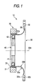
- Fig. 1 is a sectional side elevation of a wave gear device according to a first embodiment of the invention.
- Fig. 2 is an enlarged sectional side elevation of a portion of a flex spline shown in Fig. 1.
- Fig. 3 is a sectional side elevation of a wave gear device according to a second embodiment of the invention.
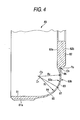
- Fig. 4 is an enlarged sectional side elevation of a portion of a flex spline shown in Fig. 3.
- Modes of embodiment of the invention are described in the following with reference to the accompanying drawings.
- At first, the constitution of a wave gear device according to a first embodiment is described.
- As shown in Fig. 1, a silk hat type
wave gear device 10 is provided with: a thickcircular spline 20 acting as an annular internal tooth gear havinginternal teeth 21 formed thereon; a silk hat shapedflex spline 30 as a flexible external tooth gear having anexternal tooth portion 31 havingexternal teeth 31a formed to mesh partially with theinternal teeth 21 and arranged on the inner side of thecircular spline 20; and awave generator 40 arranged on the inner side of theflex spline 30 and acting as a wave generator for rotating theflex spline 30 with respect to thecircular spline 20 while warping theflex spline 30. - The
flex spline 30 includes aboss portion 32 as a fixed portion to be fixed on the not-shown external member, and a connectingportion 33 for connecting theexternal tooth portion 31 and theboss portion 32. - On the other hand, the
wave generator 40 includes anelliptical cam 41 and a thin bearing 42 fitted on the outer circumference of thecam 41. - The connecting
portion 33 of theflex spline 30 is so shaped that the sectional shape cut in a plane extending through the axis ofrotation 30a (as referred to Fig. 1) of theflex spline 30 is gradually reduced in thickness from the side of theexternal tooth portion 31 and theboss portion 32 toward the substantial center, as shown in Fig. 2. Moreover, the connectingportion 33 is bulged to the side of aface 32b opposed to theexternal tooth portion 31 of theboss portion 32 with respect to aface 32a on the side of two confrontingexternal tooth portion 31 on the sectional shape cut on a plane extending through the axis ofrotation 30a. - Here, an
outer line 33a is formed of anarc 34 as a first arc leading to theexternal tooth portion 31 and theboss portion 32 and having a radius R1 and a center position O1. On the other hand, anouter line 33b is formed of both anarc 35 as a second arc leading to theexternal tooth portion 31 and having a radius R2 and acenter portion 02, and anarc 36 leading to thearc 35 and theboss portion 32 and having a radius R3 and acenter position 03. Here, thearc 34 and thearc 35 form the substantially centralthinnest portion 37 having the least thickness of the sectional shape of the connectingportion 33, as cut in the plane extending through the axis ofrotation 30a. Specifically, the points, at which the straight lines extending through the center position O1 of the first arc and thecenter position 02 of the second arc intersect with the first and second arcs, are individually located at the center of the connectingportion 33. Moreover, the radius R1 is smaller than the radius R2, and the distance from thethinnest portion 37 to the center position is shorter than the distance from thethinnest portion 37 to thecenter position 02. - Next, the actions of the silk hat type
wave gear device 10 are described. - In the silk hat type
wave gear device 10, for example, when the rotary motion is inputted from the input shaft of an industrial robot to thecam 41 of thewave generator 40 while thecircular spline 20, theboss portion 32 of theflex spline 30 and thecam 41 of thewave generator 40 being fixed to the casing, the output shaft and the input shaft of the industrial robot, respectively, the rotary motion inputted to thecam 41 of thewave generator 40 is internally reduced in speed, and is outputted from theboss portion 32 of theflex spline 30 to the output shaft. - In the silk hat type
wave gear device 10, when the rotary motion inputted to thecam 41 of thewave generator 40 is internally reduced in speed and outputted from theboss portion 32 of theflex spline 30, the torque is transmitted from thecircular spline 20 to theflex spline 30. The sectional shape, when cut in a plane extending through the axis ofrotation 30a of theflex spline 30, of the connectingportion 33 of theflex spline 30 is gradually reduced in thickness toward the substantial center from the side of theexternal tooth portion 31 and the side of theboss portion 32. As a result, the concentration of the stress on a portion of theflex spline 30 by the torque transmitted from thecircular spline 20 to theflex spline 30 can be suppressed more than the background art. - As described hereinbefore, the silk hat type
wave gear device 10 can suppress such a concentration of stress more than the background art as might otherwise be caused at a portion of theflex spline 30 by the torque transmitted from thecircular spline 20 to theflex spline 30. Therefore, even the size and weight equivalent to those of the background art can transmit a higher torque than that of the background art, and the magnitude of the transmittable torque equivalent to that of the background art can reduce the size and weight more than the background art. - In the silk hat type
wave gear device 10, moreover, thethinnest portion 37 is formed to have a simple shape of thearc 34 and thearc 35 so that the working of theflex spline 30 can be facilitated. Here, thethinnest portion 37 may have a more complicated shape. - In the silk hat type
wave gear device 10, theouter line 33a is a complete arc, but at least one of theouter line 33a and theouter line 33b may not be a complete arc, if theouter lines wave gear device 10 has substantially arcuateouter lines outer lines - At first, the constitution of a wave gear device according to a second embodiment is described.
- Of the constitutions of the wave gear device according to this embodiment, a constitution like that of the silk hat type wave gear device 10 (as referred to Fig. 1) according to the first embodiment is omitted on its detailed description by designating it with reference numerals similar to those of the constitution of the silk hat type
wave gear device 10. - As shown in Fig. 3, a cup type
wave gear device 60 as the wave gear device according to this embodiment is similar to such a constitution that the silk hat typewave gear device 10 is provided with, in place of the flex spline 30 (as referred to Fig. 1), a thin cup-shaped flex spline 80 including anexternal tooth portion 81 having anexternal teeth 81a meshing partially with theinternal teeth 21 and acting as a flexible external tooth gear arranged on the inner side of thecircular spline 20. - The
flex spline 80 includes aboss portion 82 as a fixed portion to be fixed on the not-shown external member, and a connectingportion 83 for connecting theexternal tooth portion 81 and theboss portion 82. - The connecting
portion 83 of theflex spline 80 is so shaped that the sectional shape cut in a plane extending through the axis ofrotation 80a (as referred to Fig. 3) of theflex spline 80 is gradually reduced in thickness from the side of theexternal tooth portion 81 and theboss portion 82 toward the substantial center, as shown in Fig. 4. In the connectingportion 83, moreover, two confrontingouter lines rotation 80a are substantially arcuate. Moreover, a portion of the connectingportion 83 is partially bulged to the side of aface 82b opposed to theexternal tooth portion 81 of theboss portion 82 with respect to aface 82a on the side of theexternal tooth portion 81 of theboss portion 82. - Here, the
outer line 83a is formed of anarc 84 as a first arc leading to theexternal tooth portion 81 and theboss portion 82 and having a radius R1 and a center position O1. On the other hand, theouter line 83b is formed of both anarc 85 as a second arc leading to theexternal tooth portion 81 and having a radius R2 and a center portion O2, and anarc 86 leading to thearc 85 and theboss portion 82 and having a radius R3 and acenter position 03. Here, thearc 84 and thearc 85 form the substantially centralthinnest portion 87 having the least thickness of the sectional shape of the connectingportion 83, as cut in the plane extending through the axis ofrotation 80a. Specifically, the points, at which the straight lines extending through the center position O1 of the first arc and thecenter position 02 of the second arc intersect with the first and second arcs, are individually located at the center of the connectingportion 83. Moreover, the radius R1 is smaller than the radius R2, and the distance from thethinnest portion 87 to the center position is shorter than the distance from thethinnest portion 87 to thecenter position 02. - Next, the actions of the cup type
wave gear device 60 are described. - In the cup type
wave gear device 60, for example, when the rotary motion is inputted from the input shaft of an industrial robot to thecam 41 of thewave generator 40 while thecircular spline 20, theboss portion 82 of theflex spline 80 and thecam 41 of thewave generator 40 being fixed to the casing, the output shaft and the input shaft of the industrial robot, respectively, the rotary motion inputted to thecam 41 of thewave generator 40 is internally reduced in speed, and is outputted from theboss portion 82 of theflex spline 80 to the output shaft. - In the cup type
wave gear device 60, when the rotary motion inputted to thecam 41 of thewave generator 40 is internally reduced in speed and outputted from theboss portion 82 of theflex spline 80, the torque is transmitted from thecircular spline 20 to theflex spline 80. The sectional shape, when cut in a plane extending through the axis ofrotation 80a of theflex spline 80, of the connectingportion 83 of theflex spline 80 is gradually reduced in thickness toward the substantial center from the side of theexternal tooth portion 81 and the side of theboss portion 82. As a result, the concentration of the stress on a portion of theflex spline 80 by the torque transmitted from thecircular spline 20 to theflex spline 80 can be suppressed more than the background art. - As described hereinbefore, the cup type
wave gear device 60 can suppress such a concentration of stress more than the background art as might otherwise be caused at a portion of theflex spline 80 by the torque transmitted from thecircular spline 20 to theflex spline 80. Therefore, even the size and weight equivalent to those of the background art can transmit a higher torque than that of the background art, and the magnitude of the transmittable torque equivalent to that of the background art can reduce the size and weight more than the background art. - In the cup type
wave gear device 60, moreover, thethinnest portion 87 is formed to have a simple shape of thearc 84 and thearc 85 so that the working of theflex spline 80 can be facilitated. Here, thethinnest portion 87 may have a more complicated shape. - In the cup type
wave gear device 60, theouter line 83a is a complete arc, but at least one of theouter line 83a and theouter line 83b may not be a complete arc, if theouter lines wave gear device 60 has substantially arcuateouter lines outer lines - As has been described hereinbefore, the wave gear device according to the invention has an effect to transmit a higher torque than that of the background art, and is useful as a wave gear device to be used in the fields of industrial robots, semiconductors, medical devices and aerospaces.
Claims (3)
- A wave gear device comprising: an annular internal tooth gear having internal teeth formed thereon; a flexible external tooth gear including an external tooth portion having external teeth formed to mesh partially with said internal teeth, and arranged on the inner side of said internal tooth gear; and a wave generator arranged on the inner side of said external tooth gear for rotating said external tooth gear while warping the same with respect to said internal tooth gear, characterized:
in that said external tooth gear includes a fixed portion adapted to be fixed on an external member, and a connecting portion for connecting said external tooth portion and said fixed portion; and
in that said connecting portion is so shaped that the sectional shape cut in a plane extending through the axis of rotation of said external tooth gear is gradually reduced in shape toward the substantial center from the side of said external tooth portion and the side of said fixed portion, and that two confronting outer lines on said sectional shape are substantially arcuate. - A wave gear device as set forth in claim 1,
characterized:
in that at least a portion of one of said two outer lines is a first arc;
in that at least a portion of the other of said two outer lines is a second arc having a radius and a center position different from those of the first arc; and
in that said first arc and said second arc form the thinnest portion of the substantial center of said sectional shape. - A wave gear device as set forth in claim 1,
characterized:
in that at least a portion of one of said two outer lines is a first arc;
in that at least a portion of the other of said two outer lines is a second arc having a radius and a center position different from those of the first arc; and
in that said first arc and said second arc are so formed that a straight line smaller than the radius of said first arc and the radius of said second arm and extending through the center line of said first arc and the center line of said second arc intersects with said first arc and said second arc at the substantial center of said sectional shape of said connecting portion on the side of said external tooth portion and on the side of said fixed portion.
Applications Claiming Priority (2)
| Application Number | Priority Date | Filing Date | Title |
|---|---|---|---|
| JP2004287451A JP2006097861A (en) | 2004-09-30 | 2004-09-30 | Wave gear device |
| PCT/JP2005/018028 WO2006035907A1 (en) | 2004-09-30 | 2005-09-29 | Wave gear device |
Publications (1)
| Publication Number | Publication Date |
|---|---|
| EP1813836A1 true EP1813836A1 (en) | 2007-08-01 |
Family
ID=36119053
Family Applications (1)
| Application Number | Title | Priority Date | Filing Date |
|---|---|---|---|
| EP05788212A Withdrawn EP1813836A1 (en) | 2004-09-30 | 2005-09-29 | Wave gear device |
Country Status (7)
| Country | Link |
|---|---|
| US (1) | US20080060473A1 (en) |
| EP (1) | EP1813836A1 (en) |
| JP (1) | JP2006097861A (en) |
| KR (1) | KR20070073756A (en) |
| CN (1) | CN101031737A (en) |
| TW (1) | TW200613662A (en) |
| WO (1) | WO2006035907A1 (en) |
Families Citing this family (21)
| Publication number | Priority date | Publication date | Assignee | Title |
|---|---|---|---|---|
| US9879760B2 (en) | 2002-11-25 | 2018-01-30 | Delbert Tesar | Rotary actuator with shortest force path configuration |
| JP5697356B2 (en) * | 2010-04-06 | 2015-04-08 | キヤノン株式会社 | Wave gear device and robot arm |
| DE112011105531T5 (en) * | 2011-08-17 | 2014-05-08 | Harmonic Drive Systems Inc. | Flexible, externally toothed gear for a wave gear |
| US10414271B2 (en) | 2013-03-01 | 2019-09-17 | Delbert Tesar | Multi-speed hub drive wheels |
| US9862263B2 (en) | 2013-03-01 | 2018-01-09 | Delbert Tesar | Multi-speed hub drive wheels |
| US9365105B2 (en) | 2013-10-11 | 2016-06-14 | Delbert Tesar | Gear train and clutch designs for multi-speed hub drives |
| US10422387B2 (en) | 2014-05-16 | 2019-09-24 | Delbert Tesar | Quick change interface for low complexity rotary actuator |
| US9657813B2 (en) | 2014-06-06 | 2017-05-23 | Delbert Tesar | Modified parallel eccentric rotary actuator |
| US9915319B2 (en) | 2014-09-29 | 2018-03-13 | Delbert Tesar | Compact parallel eccentric rotary actuator |
| US11014658B1 (en) | 2015-01-02 | 2021-05-25 | Delbert Tesar | Driveline architecture for rotorcraft featuring active response actuators |
| KR101981084B1 (en) | 2015-09-29 | 2019-05-22 | 가부시키가이샤 하모닉 드라이브 시스템즈 | Sliding contact-type wave generator, strain wave gearing device, and wave-generating method |
| JP6614988B2 (en) * | 2016-02-08 | 2019-12-04 | 株式会社ハーモニック・ドライブ・システムズ | Cup-shaped flexible external gear and wave gear device |
| US10464413B2 (en) | 2016-06-24 | 2019-11-05 | Delbert Tesar | Electric multi-speed hub drive wheels |
| DE102016220919A1 (en) * | 2016-10-25 | 2018-04-26 | Schaeffler Technologies AG & Co. KG | Variable transmission arrangement for a vehicle, vehicle with the Verstellgetriebeanordnung and methods for mounting the Verstellgetriebeanordnung |
| TWI641771B (en) | 2016-12-29 | 2018-11-21 | 財團法人工業技術研究院 | Harmonic driving device |
| CN108488352A (en) * | 2018-03-09 | 2018-09-04 | 太原理工大学 | A kind of no cartridge type harmonic speed reducer |
| CN109723800A (en) | 2019-03-05 | 2019-05-07 | 苏州绿的谐波传动科技股份有限公司 | A third harmonic reducer |
| JP7319822B2 (en) * | 2019-05-10 | 2023-08-02 | ナブテスコ株式会社 | Strain wave gearing |
| KR102418829B1 (en) * | 2021-01-26 | 2022-07-11 | 주식회사 에스 피 지 | Flexspline and strain wave gear device |
| CN113389874B (en) * | 2021-07-05 | 2025-08-29 | 珠海格力电器股份有限公司 | Flexspline and harmonic reducer |
| EP4488550A1 (en) * | 2023-07-03 | 2025-01-08 | Guangdong Jiya Precision Machinery Technology Co., Ltd | Flex spline, harmonic gear device, joint device for robot, design method for flex spline, and industrial robot |
Family Cites Families (8)
| Publication number | Priority date | Publication date | Assignee | Title |
|---|---|---|---|---|
| JPS61173851U (en) * | 1985-04-19 | 1986-10-29 | ||
| JPH0617888A (en) * | 1991-02-08 | 1994-01-25 | Harmonic Drive Syst Ind Co Ltd | Flexible cup-shaped member in a harmonic transmission |
| CA2183251C (en) * | 1994-12-14 | 2005-10-18 | Noboru Takizawa | Silk hat type flexible mesh engagement gear device |
| JP3580506B2 (en) * | 1994-12-14 | 2004-10-27 | 株式会社ハーモニック・ドライブ・システムズ | Silk hat type flexible meshing gear device |
| JPH08312731A (en) * | 1995-05-19 | 1996-11-26 | Harmonic Drive Syst Ind Co Ltd | Top hat wave gear device |
| JPH09273610A (en) * | 1996-04-04 | 1997-10-21 | Harmonic Drive Syst Ind Co Ltd | Top hat type flexible meshing gear unit |
| DE69723291T2 (en) * | 1997-10-02 | 2004-04-22 | Harmonic Drive Systems Inc. | ELASTIC GEAR |
| JP4685383B2 (en) * | 2004-08-18 | 2011-05-18 | 株式会社ハーモニック・ドライブ・システムズ | Wave gear device |
-
2004
- 2004-09-30 JP JP2004287451A patent/JP2006097861A/en active Pending
-
2005
- 2005-09-29 EP EP05788212A patent/EP1813836A1/en not_active Withdrawn
- 2005-09-29 CN CNA2005800333189A patent/CN101031737A/en active Pending
- 2005-09-29 US US11/575,913 patent/US20080060473A1/en not_active Abandoned
- 2005-09-29 KR KR1020077007026A patent/KR20070073756A/en not_active Withdrawn
- 2005-09-29 WO PCT/JP2005/018028 patent/WO2006035907A1/en not_active Ceased
- 2005-09-30 TW TW094134393A patent/TW200613662A/en unknown
Non-Patent Citations (1)
| Title |
|---|
| See references of WO2006035907A1 * |
Also Published As
| Publication number | Publication date |
|---|---|
| TW200613662A (en) | 2006-05-01 |
| KR20070073756A (en) | 2007-07-10 |
| JP2006097861A (en) | 2006-04-13 |
| WO2006035907A1 (en) | 2006-04-06 |
| CN101031737A (en) | 2007-09-05 |
| US20080060473A1 (en) | 2008-03-13 |
Similar Documents
| Publication | Publication Date | Title |
|---|---|---|
| US20080060473A1 (en) | Wave Gear Device | |
| CN107044527B (en) | Cup-shaped flexible external gear and cup-type wave gear device | |
| JP4248334B2 (en) | Wave gear device | |
| KR101742203B1 (en) | Flexible externally toothed gear for wave gear device | |
| US20110252921A1 (en) | Industrial robot | |
| EP3470704B1 (en) | Link operating device | |
| US20160305527A1 (en) | Motor-incorporating reducer | |
| US8821333B2 (en) | Planetary gear mechanism | |
| JP2015209931A (en) | Wave gear device and robot arm | |
| KR101100825B1 (en) | Two stage plastic harmonic reducer | |
| TWI698314B (en) | Manipulator and deflection meshing gear device | |
| JP2001221298A (en) | Eccentric oscillating reduction gear | |
| JP2014066280A (en) | Gear mechanism, decelerator, and robot arm | |
| EP3034907A1 (en) | Reducer | |
| JP2021169862A (en) | Rotation deceleration transmission device | |
| KR102687244B1 (en) | Series of reducer device, Constructoin method thereof, and Manufacturing method thereof | |
| EP3550178B1 (en) | External gear of wave gear device | |
| JP2023552310A (en) | Flexspline and harmonic reducer equipped with it | |
| JP2023184669A (en) | gear unit | |
| KR20160010553A (en) | Fastening structure for fastening driven member to wave gear device unit, and wave gear device unit | |
| JP2010014177A (en) | Eccentric rocking type gear transmission device | |
| JP2007016838A (en) | Top hat wave gear device | |
| CN109154362B (en) | Rotary Actuator with Wave Gear Reducer | |
| US20030233909A1 (en) | Silk hat shaped wave gear device | |
| US20170299035A1 (en) | Differential device |
Legal Events
| Date | Code | Title | Description |
|---|---|---|---|
| PUAI | Public reference made under article 153(3) epc to a published international application that has entered the european phase |
Free format text: ORIGINAL CODE: 0009012 |
|
| 17P | Request for examination filed |
Effective date: 20070321 |
|
| AK | Designated contracting states |
Kind code of ref document: A1 Designated state(s): DE GB SE |
|
| DAX | Request for extension of the european patent (deleted) | ||
| RBV | Designated contracting states (corrected) |
Designated state(s): DE GB SE |
|
| STAA | Information on the status of an ep patent application or granted ep patent |
Free format text: STATUS: THE APPLICATION HAS BEEN WITHDRAWN |
|
| 18W | Application withdrawn |
Effective date: 20100618 |