EP1813503B1 - Trim plate for steering wheel - Google Patents
Trim plate for steering wheel Download PDFInfo
- Publication number
- EP1813503B1 EP1813503B1 EP20070001887 EP07001887A EP1813503B1 EP 1813503 B1 EP1813503 B1 EP 1813503B1 EP 20070001887 EP20070001887 EP 20070001887 EP 07001887 A EP07001887 A EP 07001887A EP 1813503 B1 EP1813503 B1 EP 1813503B1
- Authority
- EP
- European Patent Office
- Prior art keywords
- steering wheel
- back cover
- wheel assembly
- trim plate
- covering layer
- Prior art date
- Legal status (The legal status is an assumption and is not a legal conclusion. Google has not performed a legal analysis and makes no representation as to the accuracy of the status listed.)
- Ceased
Links
Images

Classifications
-
- B—PERFORMING OPERATIONS; TRANSPORTING
- B60—VEHICLES IN GENERAL
- B60R—VEHICLES, VEHICLE FITTINGS, OR VEHICLE PARTS, NOT OTHERWISE PROVIDED FOR
- B60R21/00—Arrangements or fittings on vehicles for protecting or preventing injuries to occupants or pedestrians in case of accidents or other traffic risks
- B60R21/02—Occupant safety arrangements or fittings, e.g. crash pads
- B60R21/04—Padded linings for the vehicle interior ; Energy absorbing structures associated with padded or non-padded linings
- B60R21/05—Padded linings for the vehicle interior ; Energy absorbing structures associated with padded or non-padded linings associated with the steering wheel, steering hand lever or steering column
-
- B—PERFORMING OPERATIONS; TRANSPORTING
- B62—LAND VEHICLES FOR TRAVELLING OTHERWISE THAN ON RAILS
- B62D—MOTOR VEHICLES; TRAILERS
- B62D1/00—Steering controls, i.e. means for initiating a change of direction of the vehicle
- B62D1/02—Steering controls, i.e. means for initiating a change of direction of the vehicle vehicle-mounted
- B62D1/04—Hand wheels
- B62D1/10—Hubs; Connecting hubs to steering columns, e.g. adjustable
-
- B—PERFORMING OPERATIONS; TRANSPORTING
- B62—LAND VEHICLES FOR TRAVELLING OTHERWISE THAN ON RAILS
- B62D—MOTOR VEHICLES; TRAILERS
- B62D1/00—Steering controls, i.e. means for initiating a change of direction of the vehicle
- B62D1/02—Steering controls, i.e. means for initiating a change of direction of the vehicle vehicle-mounted
- B62D1/04—Hand wheels
- B62D1/11—Hand wheels incorporating energy-absorbing arrangements, e.g. by being yieldable or collapsible
-
- Y—GENERAL TAGGING OF NEW TECHNOLOGICAL DEVELOPMENTS; GENERAL TAGGING OF CROSS-SECTIONAL TECHNOLOGIES SPANNING OVER SEVERAL SECTIONS OF THE IPC; TECHNICAL SUBJECTS COVERED BY FORMER USPC CROSS-REFERENCE ART COLLECTIONS [XRACs] AND DIGESTS
- Y10—TECHNICAL SUBJECTS COVERED BY FORMER USPC
- Y10T—TECHNICAL SUBJECTS COVERED BY FORMER US CLASSIFICATION
- Y10T74/00—Machine element or mechanism
- Y10T74/20—Control lever and linkage systems
- Y10T74/20576—Elements
- Y10T74/20732—Handles
- Y10T74/20834—Hand wheels
Definitions
- the present invention relates generally to a steering wheel assembly.
- Steering wheel trim plates are fitted on a vehicle steering wheel to conceal the armature, horn/airbag bracket, etc. Specifically, one trim plate is fitted to each side of the steering wheel airbag cover for a total of two trim plates per steering wheel assembly. As an alternative, a single U-shaped trim plate may be used.
- One type of steering wheel includes a metal steering wheel armature to which is molded a urethane covering layer.
- a back cover connects to the armature and covering layer to cover the armature. The back cover can also be molded integrally with the covering layer urethane.
- the trim plates cover front portions of the armature on either side of the airbag assembly.
- DE 296 15 261 U1 discloses a cover for an airbag module integrated into a steering wheel, which cover is formed as an elastic hollow body enclosing a boss body of the steering wheel.
- the hollow body includes an upper wall, a bottom wall and side walls and can be opened in its bottom wall to be put over the boss body.
- EP 1 004 496 A2 discloses a steering wheel assembly with a steering wheel body, which comprises an annular ring , and a pad disposed in the centre of the ring. A plastic lower cover is provided to enclose the under side of this steering wheel body.
- FR 2 401 816 discloses a steering wheel with an armature completely covered by an envelope consisting of an elastic material.
- the trim plate is attached to the covering layer and to the back cover by snap fitting.
- This enables a simple mounting and demounting and ensures a proper fit and finish, for the snap-fit connection is directly between the components, with which the trim plate must proper fit. Any variation in the position of the armature relative to the covering layer or back cover will not affect the alignment of the finish surfaces.
- the trim plates can pivot and flex sufficiently to provide ideal alignment. Also, proper fit and finish can be adjusted and tuned simply by modifying the snap-fit connectors on the trim panel, without needing to modify the connectors on the back cover or the covering layer.
- trim plates are easily assembled to the steering wheel assembly because of the snap-fit connections.
- the trim plates can also be easily removed and replaced, if necessary. Separate fasteners are eliminated, reducing the number of parts and installation time. Appended sub claims are directed towards advantageous embodiments of the inventive steering wheel assembly.
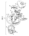
- Figure 1 is an exploded perspective view of a steering wheel assembly according to the present invention.
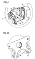
- Figure 2 is a perspective view of the partially-assembled steering wheel and back cover of Figure 1 .
- Figure 2A is an enlarged view of the portion A of Figure 2 .
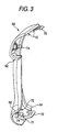
- Figure 3 is a perspective view of one of the trim plates of Figure 1 .
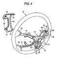
- FIG 4 is a rear perspective view of the steering wheel and trim plates (horn bracket not shown for clarity).
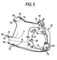
- Figure 5 is an interior perspective view of the back cover of Figure 1 .
- Figure 6 is a rear perspective view of the assembly of Figure 1 .
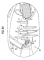
- Figure 6A is an enlarged view of the area 6A of Figure 6 .
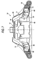
- Figure 7 is a section view through the assembled steering wheel assembly of Figure 1 .
- a steering wheel assembly 10 according to the present invention is shown in Figure 1 .
- the steering wheel assembly 10 has a steering wheel including a metal armature 12 having radially extending spokes 14 and a urethane covering layer 16.
- the covering layer 16 includes integrally molded spoke ends 18 extending radially inwardly from a ring portion 20, each overmolded over one of the spokes 14 of the armature 12.
- the steering wheel assembly 10 further includes a molded plastic back cover 26 having a rear wall 28 with a central opening 30. Side walls 32 extend forwardly from the rear wall 28, including spoke portions 34. The rear wall 28 includes connectors 36.
- the back cover 26 could alternatively be molded integrally with the covering layer 16.
- a stamped metal horn bracket 44 includes a spring connector 46 for connecting the horn bracket 44 to a floating horn switch/airbag assembly 48 having a front panel 50.
- An optional electrical switch assembly 54 can be included to control in-vehicle entertainment, climate control or cruise control, etc.
- a pair of plastic trim plates (or bezels) 60 each include a pair of spoke portions 62 extending outward and a flange 64 on an inner edge.
- FIG 2 is a perspective view of the partially-assembled steering wheel back cover 26 and one trim plate 60 of Figure 1 .
- Each of the spoke ends 18 of the covering layer 16 includes a molded snap-fit receptacle 66.
- the trim plates 60 (one shown in Figure 2 ) connect to the covering layer 16 and back cover 26 over portions of the spokes 14 of the armature 12.
- Figure 2A is an enlarged view of the portion A of Figure 2 .
- the connectors 36 of the back cover 26 snap-fit to the spokes 14 of the armature 12.
- the rear wall 28 of the back cover 26 may also be connected to the armature 12 by a fastener, such as by a screw.
- FIG 3 is a perspective view of one of the trim plates 60 of Figure 1 .
- a pair of loop connectors 70 protrude downwardly from the interior surface of an inner end of the trim plate 60.
- the loop connectors 70 are adjacent the inner flange 64 and a pair of male snap-fit connectors 74 are adjacent an outer end.
- the trim plate 60 includes protruding alignment fingers 72 adjacent loop connectors 70.
- FIG 4 is a rear perspective view of the covering layer 16, armature 12 and trim plates 60 (horn bracket 44 not shown for clarity).
- the trim plates 60 are connected to the covering layer 16 by snap-fitting the male snap-fit connectors 74 into the receptacles 66 on the spoke ends 18.
- FIG 5 is a perspective view of the back cover 26.
- the spoke portions 34 of the back cover include connectors 76 complementary to loop connectors 70 on trim plates 60 ( Figure 4 ) by protruding inwardly from an inner surface of the back cover 26.
- Alignment fingers 78 protrude upwardly from edges of the spoke portions 34, as do hooks 80 (for connection to the spoke ends 18 of the covering layer 16) adjacent to the alignment fingers 78.
- Figure 6 is a rear perspective view of the assembled steering wheel assembly 10, with the horn bracket 44 not shown and with the armature 12 cut away for clarity.
- the trim plates 60 mate with the spoke ends 18 oand the back cover 26. Because the trim plates 60 are directly connected only to the spoke ends 18 of the covering layer 16 and the back cover 26, the trim plates 60 are automatically aligned.
- Figure 6A is an enlarged view of the area 6A of Figure 6 showing the connection of the trim plate 60 to the back cover 26.
- the alignment fingers 72, 78 interlock with the edges of the trim plate 60 and back cover 26 to ensure and maintain proper alignment.
- the loop connector 70 of the trim plate 60 snap-fits to the complementary inclined connectors 76.
- Figure 7 is a section view through the assembled steering wheel assembly 10.
- the connection of the trim plates 60 to the covering layer 16 and the back cover 26 permits variances in the position of the armature 12 relative to the covering layer 16 (in the overmolding or insert-molding process) while ensuring alignment of the trim plates 60 to the visible surfaces, the back cover 26 and the spoke ends 18 of the covering layer.
- the attachment arrangement permits the floating horn switch/airbag assembly 48 to move relative to the trim plates 60.
- a gap is provided between the front panel 50 of the floating horn switch/airbag assembly 48 and the flanges 64 of the trim plates 60 so that the floating horn switch/airbag assembly 48 can be moved relative to the trim plate 60.
- the trim plates 60 are easily assembled to the steering wheel assembly 10 because of the snap-fit connections.
- the trim plates 60 can also be easily removed and replaced, if necessary. Because the trim plates 60 are connected only to the covering layer 16 and the back cover 26, the trim plates 60 are assured of aligning properly with the finish surfaces of the covering layer 16 and the back cover 26 ( Figure 6 ). Any variation in the position of the armature 12 relative to the covering layer 16 or back cover 26 will not affect the alignment of the finish surfaces.
- the trim plates 60 can pivot and flex sufficiently to ensure ideal fit and finish. Separate fasteners are eliminated, reducing the number of parts and installation time.
- the trim plates 60 remain fastened to the covering layer 16 and back cover 26 even in the event of airbag deployment.
- the size, shape and location of the loop connectors 70 and the male snap-fit connectors 74 can be tuned and adjusted to change the ease of assembly and retention strength or to change the alignment of the trim plates 60 relative to the adjacent fit and finish parts. Because the trim plates 60 are directly connected to the same two components with which the trim plates 60 must provide proper fit and finish, proper fit and finish is ensured and can be adjusted simply by modifying the connectors 70, 74.
Landscapes
- Engineering & Computer Science (AREA)
- Mechanical Engineering (AREA)
- Chemical & Material Sciences (AREA)
- Combustion & Propulsion (AREA)
- Transportation (AREA)
- Steering Controls (AREA)
- Air Bags (AREA)
Description
- The present invention relates generally to a steering wheel assembly.
- Steering wheel trim plates (also known as "steering wheel bezels") are fitted on a vehicle steering wheel to conceal the armature, horn/airbag bracket, etc. Specifically, one trim plate is fitted to each side of the steering wheel airbag cover for a total of two trim plates per steering wheel assembly. As an alternative, a single U-shaped trim plate may be used. One type of steering wheel includes a metal steering wheel armature to which is molded a urethane covering layer. A back cover connects to the armature and covering layer to cover the armature. The back cover can also be molded integrally with the covering layer urethane. The trim plates cover front portions of the armature on either side of the airbag assembly.
- In the prior art, these trim plates have been held in place with separate fasteners that connect to the armature. This arrangement has several distinct disadvantages. First, any variation in the positioning of the insert-molded armature relative to the covering layer will also affect the positioning of the trim plates, resulting in poor fit and finish. As a result, the trim plates may not align properly with the covering layer and the back cover. Second, the additional fasteners in this arrangement require extra expense both in terms of parts and labor.
-
DE 37 00 422 A1 , from which preamble of appended claim 1 starts, discloses a steering wheel assembly with its back cover being directly attached to the molded covering layer of the armature and to a boss assembly, by which the steering wheel assembly is fixed to a steering column. -
DE 296 15 261 U1 discloses a cover for an airbag module integrated into a steering wheel, which cover is formed as an elastic hollow body enclosing a boss body of the steering wheel. The hollow body includes an upper wall, a bottom wall and side walls and can be opened in its bottom wall to be put over the boss body. -
EP 1 004 496 A2 discloses a steering wheel assembly with a steering wheel body, which comprises an annular ring , and a pad disposed in the centre of the ring. A plastic lower cover is provided to enclose the under side of this steering wheel body. -
FR 2 401 816 - It is an object of the invention to provide a steering wheel assembly according to the preamble of claim 1, which can be easily assembled and has a proper appearance.
- A solution of this object is achieved by a steering wheel assembly according to appended claim 1.
- With inventive steering wheel assembly the trim plate is attached to the covering layer and to the back cover by snap fitting. This enables a simple mounting and demounting and ensures a proper fit and finish, for the snap-fit connection is directly between the components, with which the trim plate must proper fit. Any variation in the position of the armature relative to the covering layer or back cover will not affect the alignment of the finish surfaces. The trim plates can pivot and flex sufficiently to provide ideal alignment. Also, proper fit and finish can be adjusted and tuned simply by modifying the snap-fit connectors on the trim panel, without needing to modify the connectors on the back cover or the covering layer.
- The trim plates are easily assembled to the steering wheel assembly because of the snap-fit connections. The trim plates can also be easily removed and replaced, if necessary. Separate fasteners are eliminated, reducing the number of parts and installation time.
Appended sub claims are directed towards advantageous embodiments of the inventive steering wheel assembly. - Other advantages of the present invention can be understood by reference to the following detailed description when considered in connection with the accompanying drawings wherein:
-
Figure 1 is an exploded perspective view of a steering wheel assembly according to the present invention. -
Figure 2 is a perspective view of the partially-assembled steering wheel and back cover ofFigure 1 . -
Figure 2A is an enlarged view of the portion A ofFigure 2 . -
Figure 3 is a perspective view of one of the trim plates ofFigure 1 . -
Figure 4 is a rear perspective view of the steering wheel and trim plates (horn bracket not shown for clarity). -
Figure 5 is an interior perspective view of the back cover ofFigure 1 . -
Figure 6 is a rear perspective view of the assembly ofFigure 1 . -
Figure 6A is an enlarged view of thearea 6A ofFigure 6 . -
Figure 7 is a section view through the assembled steering wheel assembly ofFigure 1 . - A
steering wheel assembly 10 according to the present invention is shown inFigure 1 . Thesteering wheel assembly 10 has a steering wheel including ametal armature 12 having radially extendingspokes 14 and a urethane coveringlayer 16. The coveringlayer 16 includes integrally molded spoke ends 18 extending radially inwardly from aring portion 20, each overmolded over one of thespokes 14 of thearmature 12. - The
steering wheel assembly 10 further includes a moldedplastic back cover 26 having arear wall 28 with acentral opening 30.Side walls 32 extend forwardly from therear wall 28, including spokeportions 34. Therear wall 28 includesconnectors 36. Theback cover 26 could alternatively be molded integrally with the coveringlayer 16. - A stamped
metal horn bracket 44 includes aspring connector 46 for connecting thehorn bracket 44 to a floating horn switch/airbag assembly 48 having afront panel 50. An optionalelectrical switch assembly 54 can be included to control in-vehicle entertainment, climate control or cruise control, etc. A pair of plastic trim plates (or bezels) 60 each include a pair ofspoke portions 62 extending outward and aflange 64 on an inner edge. -
Figure 2 is a perspective view of the partially-assembled steeringwheel back cover 26 and onetrim plate 60 ofFigure 1 . Each of the spoke ends 18 of the coveringlayer 16 includes a molded snap-fit receptacle 66. The trim plates 60 (one shown inFigure 2 ) connect to the coveringlayer 16 andback cover 26 over portions of thespokes 14 of thearmature 12. -
Figure 2A is an enlarged view of the portion A ofFigure 2 . Theconnectors 36 of theback cover 26 snap-fit to thespokes 14 of thearmature 12. Therear wall 28 of theback cover 26 may also be connected to thearmature 12 by a fastener, such as by a screw. -
Figure 3 is a perspective view of one of thetrim plates 60 ofFigure 1 . A pair ofloop connectors 70 protrude downwardly from the interior surface of an inner end of thetrim plate 60. Theloop connectors 70 are adjacent theinner flange 64 and a pair of male snap-fit connectors 74 are adjacent an outer end. Thetrim plate 60 includes protrudingalignment fingers 72adjacent loop connectors 70. -
Figure 4 is a rear perspective view of the coveringlayer 16,armature 12 and trim plates 60 (horn bracket 44 not shown for clarity). Thetrim plates 60 are connected to thecovering layer 16 by snap-fitting the male snap-fit connectors 74 into thereceptacles 66 on the spoke ends 18. -
Figure 5 is a perspective view of theback cover 26. Thespoke portions 34 of the back cover includeconnectors 76 complementary toloop connectors 70 on trim plates 60 (Figure 4 ) by protruding inwardly from an inner surface of theback cover 26.Alignment fingers 78 protrude upwardly from edges of thespoke portions 34, as do hooks 80 (for connection to the spoke ends 18 of the covering layer 16) adjacent to thealignment fingers 78. -
Figure 6 is a rear perspective view of the assembledsteering wheel assembly 10, with thehorn bracket 44 not shown and with thearmature 12 cut away for clarity. Thetrim plates 60 mate with the spoke ends 18 oand theback cover 26. Because thetrim plates 60 are directly connected only to the spoke ends 18 of thecovering layer 16 and theback cover 26, thetrim plates 60 are automatically aligned. -
Figure 6A is an enlarged view of thearea 6A ofFigure 6 showing the connection of thetrim plate 60 to theback cover 26. Thealignment fingers trim plate 60 andback cover 26 to ensure and maintain proper alignment. Theloop connector 70 of thetrim plate 60 snap-fits to the complementaryinclined connectors 76. -
Figure 7 is a section view through the assembledsteering wheel assembly 10. The connection of thetrim plates 60 to thecovering layer 16 and theback cover 26 permits variances in the position of thearmature 12 relative to the covering layer 16 (in the overmolding or insert-molding process) while ensuring alignment of thetrim plates 60 to the visible surfaces, theback cover 26 and the spoke ends 18 of the covering layer. Additionally, the attachment arrangement permits the floating horn switch/airbag assembly 48 to move relative to thetrim plates 60. In particular, a gap is provided between thefront panel 50 of the floating horn switch/airbag assembly 48 and theflanges 64 of thetrim plates 60 so that the floating horn switch/airbag assembly 48 can be moved relative to thetrim plate 60. - The
trim plates 60 are easily assembled to thesteering wheel assembly 10 because of the snap-fit connections. Thetrim plates 60 can also be easily removed and replaced, if necessary. Because thetrim plates 60 are connected only to thecovering layer 16 and theback cover 26, thetrim plates 60 are assured of aligning properly with the finish surfaces of thecovering layer 16 and the back cover 26 (Figure 6 ). Any variation in the position of thearmature 12 relative to thecovering layer 16 orback cover 26 will not affect the alignment of the finish surfaces. Thetrim plates 60 can pivot and flex sufficiently to ensure ideal fit and finish. Separate fasteners are eliminated, reducing the number of parts and installation time. Because theloop connector 70 is located on a lower location at inside of thetrim plate 60, and thealignment fingers loop connector 70 and theinclined connectors 76, thetrim plates 60 remain fastened to thecovering layer 16 andback cover 26 even in the event of airbag deployment. - As an additional benefit, the size, shape and location of the
loop connectors 70 and the male snap-fit connectors 74 can be tuned and adjusted to change the ease of assembly and retention strength or to change the alignment of thetrim plates 60 relative to the adjacent fit and finish parts. Because thetrim plates 60 are directly connected to the same two components with which thetrim plates 60 must provide proper fit and finish, proper fit and finish is ensured and can be adjusted simply by modifying theconnectors
Claims (16)
- A steering wheel assembly comprising:an armature (12) having a plurality of spokes (14);a molded covering layer (16) secured to the spokes of the armature;a back cover (26) secured to the armature; anda trim plate (60) directly attached to the covering layer and the back cover,characterized in that
the trim plate is snap-fit to the covering layer (16) and is snap-fit to the back cover (26). - The steering wheel assembly of claim 1, wherein the trim plate (60) is not secured to the armature (12) other than via the covering layer (16) and the back cover (26).
- The steering wheel assembly of any of claims 1 or 2, wherein the covering layer (16) includes a ring portion (20) and a spoke end (18) extending radially inwardly from the ring portion, the spoke end overmolded over one of the spokes (14) of the armature (12).
- The steering wheel assembly of claim 3 wherein the trim plate (60) is snap-fit to the spoke end (18).
- The steering wheel assembly of any of claims 1 to 4 wherein the armature (12) is metal and the back cover (26) is a molded polymer.
- The steering wheel assembly of any of claims 1 to 6 further including a floating horn assembly (48) mounted to the armature (12).
- The steering wheel assembly of claim 6 further including a horn bracket (44) fixed to the armature (12), the floating horn assembly (48) movable relative to the horn bracket and relative to the trim plate (60), wherein the floating horn assembly includes a front panel (50) that overlaps over a flange (64) on the trim plate (60).
- The steering wheel assembly of any of claims 1 to 7 wherein the trim plate (60) snap-fits with the back cover (26) at a location that is inside of a location where the trim plate snap-fits with the covering layer (16).
- The steering wheel assembly of any of claims 1 to 7 wherein the trim plate (60) snap-fits with the back cover (26) at a location that is under the location where the trim plate snap-fits with the covering layer (16).
- The steering wheel assembly of any of claims 1 to 7 wherein the trim plate (60) snap-fits with the back cover (26) at a location that is between a location where the trim plate snap-fits with the covering layer (16) and a location where the back cover is secured to the armature (12).
- The steering wheel assembly according to claim 3, wherein the trim plate (60) is provided with a pair of loop connectors (70) protruding downwardly from an interior surface of an inner end of the trim plate and engaged by complementary connectors (76) provided on spoke portions (34) of the back cover (26) and the trim plate (60) is further provided with a pair of male snap-fit connectors (74) adjacent an outer end thereof and snap-fitted into receptacles (66) provided on the spoke ends (18) of the covering layer (16).
- The steering wheel assembly according to claim 11, wherein the trim plate (60) includes protruding alignment fingers (72) adjacent the loop connectors (70).
- The steering wheel assembly according to claim 11 or 12, wherein the back cover (26) includes hooks (80) connected to the spoke ends (18) of the covering layer (16).
- The steering wheel assembly according to claim 13, wherein spoke portions (34) of the back cover (26) include alignment fingers (78) protruding upwardly from edges thereof adjacent the hooks (80).
- The steering wheel assembly according to any of claims 1 to 14, wherein the back cover (26) includes connectors (36) which are snap-fitted to the spokes (14) of the armature (12).
- The steering wheel assembly according to any of claims 1 to 14, wherein the back cover (26) is molded integrally with the covering layer (16).
Applications Claiming Priority (1)
| Application Number | Priority Date | Filing Date | Title |
|---|---|---|---|
| US11/344,301 US8661936B2 (en) | 2006-01-31 | 2006-01-31 | Trim plate for steering wheel |
Publications (3)
| Publication Number | Publication Date |
|---|---|
| EP1813503A1 EP1813503A1 (en) | 2007-08-01 |
| EP1813503A8 EP1813503A8 (en) | 2007-10-03 |
| EP1813503B1 true EP1813503B1 (en) | 2008-12-31 |
Family
ID=38015361
Family Applications (1)
| Application Number | Title | Priority Date | Filing Date |
|---|---|---|---|
| EP20070001887 Ceased EP1813503B1 (en) | 2006-01-31 | 2007-01-29 | Trim plate for steering wheel |
Country Status (5)
| Country | Link |
|---|---|
| US (1) | US8661936B2 (en) |
| EP (1) | EP1813503B1 (en) |
| JP (1) | JP4984920B2 (en) |
| CN (1) | CN100581896C (en) |
| DE (1) | DE602007000405D1 (en) |
Cited By (1)
| Publication number | Priority date | Publication date | Assignee | Title |
|---|---|---|---|---|
| DE202020100955U1 (en) * | 2020-02-21 | 2021-05-25 | ZF Automotive Safety Germany GmbH | Steering wheel assembly and cover element for such a steering wheel assembly |
Families Citing this family (11)
| Publication number | Priority date | Publication date | Assignee | Title |
|---|---|---|---|---|
| JP5576026B2 (en) | 2008-03-03 | 2014-08-20 | 本田技研工業株式会社 | Vehicle steering device |
| KR200470020Y1 (en) * | 2009-07-07 | 2013-11-20 | (주)엘지하우시스 | Fixing structure of steering wheel and settling members and horn moduel fixing structure using same |
| DE102009041714A1 (en) * | 2009-09-16 | 2011-03-24 | GM Global Technology Operations, Inc., Detroit | Steering arrangement for a vehicle |
| JP5964650B2 (en) * | 2012-05-14 | 2016-08-03 | 日本プラスト株式会社 | Steering wheel with finisher |
| US9027437B2 (en) * | 2012-05-29 | 2015-05-12 | GM Global Technology Operations LLC | Steering wheels, steering wheel and steering column assemblies, and methods for assembling steering wheels and steering columns |
| CN103448553B (en) * | 2012-05-31 | 2017-07-11 | 北汽福田汽车股份有限公司 | The mounting structure and steering wheel of steering wheel button |
| JP6147643B2 (en) * | 2013-10-28 | 2017-06-14 | 日本プラスト株式会社 | Steering wheel |
| US9242614B2 (en) * | 2014-03-07 | 2016-01-26 | Autoliv Asp, Inc. | Airbag systems with energy-absorbing components |
| KR102279701B1 (en) * | 2020-02-25 | 2021-07-20 | 주식회사 모베이스전자 | Steering wheel remote control switch |
| EP4168143B1 (en) * | 2020-06-19 | 2024-09-18 | Massimiliano Papis | Multi-piece steering wheel assembly incorporating an exchangeable spoked steering wheel |
| CN112208620A (en) * | 2020-10-15 | 2021-01-12 | 锦州锦恒汽车安全系统股份有限公司 | Flexible steering wheel |
Family Cites Families (38)
| Publication number | Priority date | Publication date | Assignee | Title |
|---|---|---|---|---|
| DE2739938A1 (en) | 1977-09-05 | 1979-03-15 | Petri Ag | STEERING WHEEL FOR MOTOR VEHICLES |
| JPS60115146U (en) * | 1984-01-12 | 1985-08-03 | 日本プラスト株式会社 | steering wheel |
| JPS6157065U (en) * | 1984-09-21 | 1986-04-17 | ||
| CA1271112A (en) | 1986-01-14 | 1990-07-03 | Nihon Plast Co., Ltd. | Steering wheel |
| JPH01128457U (en) * | 1988-02-26 | 1989-09-01 | ||
| US5152551A (en) | 1990-06-28 | 1992-10-06 | Toyoda Gosei Co., Ltd. | Steering wheel having impact absorbing member |
| JP2760248B2 (en) * | 1992-04-24 | 1998-05-28 | 豊田合成株式会社 | Steering wheel with airbag device |
| US5275455A (en) * | 1992-10-07 | 1994-01-04 | Chrysler Corporation | Integral molding snap-in attachment fastener |
| US5345721A (en) * | 1993-05-07 | 1994-09-13 | General Motors Corporation | Hook and pin fastener assembly for a door trim panel |
| US5667868A (en) * | 1993-09-14 | 1997-09-16 | The Budd Company | Outer door panel and method for molding and attaching same |
| AU683813B2 (en) | 1996-02-26 | 1997-11-20 | Toyoda Gosei Co. Ltd. | Steering wheel, mounting structure thereof and boss structure thereof |
| DE29615261U1 (en) * | 1996-09-02 | 1997-01-16 | Trw Occupant Restraint Systems Gmbh, 73551 Alfdorf | Coverage of an airbag module integrated in a vehicle steering wheel |
| US6095594A (en) * | 1998-07-21 | 2000-08-01 | Chrysler Corporation | Exterior body side cladding attachment for a motor vehicle and related method |
| US6378931B1 (en) * | 1999-10-29 | 2002-04-30 | Exatec, Llc. | Molded plastic automotive window panel and method of installation |
| JP3707323B2 (en) * | 1999-12-10 | 2005-10-19 | 豊田合成株式会社 | Ornament mounting structure on steering wheel |
| US6276109B1 (en) * | 1999-12-20 | 2001-08-21 | General Motors Corporation | Motor vehicle trim panel assembly and method |
| JP2001328425A (en) * | 2000-05-19 | 2001-11-27 | Nippon Pop Rivets & Fasteners Ltd | Molding installing device |
| SE517015C2 (en) * | 2000-07-14 | 2002-04-02 | Volvo Personvagnar Ab | Mounting module intended for a steering wheel in a vehicle and the procedure for mounting it |
| JP2002093273A (en) * | 2000-09-18 | 2002-03-29 | Tokai Rika Co Ltd | Mounting structure of handle switch for vehicle |
| JP2002120730A (en) * | 2000-10-19 | 2002-04-23 | Tokai Rika Co Ltd | Mounting structure of steering switch |
| US6460874B1 (en) * | 2000-11-20 | 2002-10-08 | Trw Vehicle Safety Systems Inc. | Air bag module deployment door with snap-in feature |
| US6681543B2 (en) * | 2001-03-28 | 2004-01-27 | Toyoda Gosei Co., Ltd. | Vehicle molding and method for attaching the vehicle molding |
| JP3895131B2 (en) * | 2001-05-29 | 2007-03-22 | 日本プラスト株式会社 | Steering wheel |
| US6422643B1 (en) * | 2001-12-12 | 2002-07-23 | Guardian Industries Corp. | System for attaching front grill or other trim component to vehicle |
| US6813865B2 (en) * | 2002-06-12 | 2004-11-09 | Lear Corporation | Fastener assembly for use with a trim panel |
| JP2004142553A (en) * | 2002-10-23 | 2004-05-20 | Alps Electric Co Ltd | On-vehicle steering switch |
| JP3994830B2 (en) * | 2002-09-04 | 2007-10-24 | 豊田合成株式会社 | Steering wheel |
| US6932416B2 (en) * | 2003-01-09 | 2005-08-23 | Lear Corporation | Vehicular door trim having a molded-in substrate fastener |
| US6874386B2 (en) * | 2003-03-07 | 2005-04-05 | Key Safety Systems, Inc. | Steering wheel armature with detachable rim |
| US6966594B2 (en) * | 2004-03-01 | 2005-11-22 | Lear Corporation | Vehicle trim panel and method of reducing BSR |
| DE102004022634A1 (en) * | 2004-05-07 | 2005-12-15 | Dr.Ing.H.C. F. Porsche Ag | Covers for a steering wheel |
| DE102004027870A1 (en) * | 2004-05-14 | 2005-12-08 | Trw Automotive Safety Systems Gmbh | Steering wheel for a motor vehicle |
| JP4458528B2 (en) * | 2004-07-29 | 2010-04-28 | 日本プラスト株式会社 | Steering wheel |
| JP2006044390A (en) * | 2004-08-02 | 2006-02-16 | Honda Motor Co Ltd | Switch case mounting structure |
| US7490852B2 (en) * | 2005-03-21 | 2009-02-17 | Delphi Technologies, Inc. | Apparatus and method for providing a horn contact mechanism |
| US7556282B2 (en) * | 2006-03-09 | 2009-07-07 | Toyoda Gosei Co. Ltd. | Steering wheel assembly |
| US8505410B2 (en) * | 2006-08-31 | 2013-08-13 | Autoliv Asp, Inc. | Two-piece steering wheel back-cover for improved safety performance |
| US7654563B2 (en) * | 2008-04-02 | 2010-02-02 | Autoliv Asp, Inc. | Cover to wheel attachment method for improved gap control |
-
2006
- 2006-01-31 US US11/344,301 patent/US8661936B2/en not_active Expired - Fee Related
-
2007
- 2007-01-29 DE DE200760000405 patent/DE602007000405D1/en active Active
- 2007-01-29 JP JP2007018043A patent/JP4984920B2/en not_active Expired - Fee Related
- 2007-01-29 EP EP20070001887 patent/EP1813503B1/en not_active Ceased
- 2007-01-31 CN CN 200710003082 patent/CN100581896C/en not_active Expired - Fee Related
Cited By (2)
| Publication number | Priority date | Publication date | Assignee | Title |
|---|---|---|---|---|
| DE202020100955U1 (en) * | 2020-02-21 | 2021-05-25 | ZF Automotive Safety Germany GmbH | Steering wheel assembly and cover element for such a steering wheel assembly |
| WO2021165351A1 (en) | 2020-02-21 | 2021-08-26 | ZF Automotive Safety Germany GmbH | Steering wheel assembly and cover element for a steering wheel assembly of this kind |
Also Published As
| Publication number | Publication date |
|---|---|
| JP4984920B2 (en) | 2012-07-25 |
| CN100581896C (en) | 2010-01-20 |
| US20070193399A1 (en) | 2007-08-23 |
| EP1813503A1 (en) | 2007-08-01 |
| EP1813503A8 (en) | 2007-10-03 |
| US8661936B2 (en) | 2014-03-04 |
| CN101074026A (en) | 2007-11-21 |
| JP2007204040A (en) | 2007-08-16 |
| DE602007000405D1 (en) | 2009-02-12 |
Similar Documents
| Publication | Publication Date | Title |
|---|---|---|
| EP1813503A1 (en) | Trim plate for steering wheel | |
| EP1658199B1 (en) | Vehicle body panel with integral clip | |
| US5470099A (en) | One-piece steering wheel assembly | |
| US6840537B2 (en) | Airbag module attachment arrangement | |
| US8276961B2 (en) | Vehicle trim assembly | |
| EP2834130B1 (en) | Steering wheel with switch assembly | |
| WO1998015431A1 (en) | Snap-on airbag and horn switch module | |
| US7192057B2 (en) | Deflection fitting for a safety belt | |
| US5857728A (en) | Mounting bracket assembly for a sunshade and method of installing the same | |
| US20020141199A1 (en) | Exterior rear view mirror integral warning light | |
| US6666488B2 (en) | Bumper system for a vehicle and a method of making same | |
| EP0346154B1 (en) | Modular headliner including a wire harness | |
| EP3296157B1 (en) | Housing for a rear view element of a rear view device for a vehicle | |
| JPH10223079A (en) | Switch device | |
| US20040154429A1 (en) | Two-piece steering wheel back cover | |
| US5117549A (en) | Automotive door panels and method of assembly therefor | |
| JPH1081189A (en) | Gasbag module cover | |
| JP3891385B2 (en) | Cup holder structure | |
| US20010030413A1 (en) | Vehicle steering wheel | |
| EP0732237A1 (en) | Steering wheel assembly | |
| JPS58105836A (en) | Receptacle structure equipped with arm rest for automobile | |
| JP3876093B2 (en) | Switch device | |
| US20070068309A1 (en) | Steering column cover assembly | |
| JPH1134769A (en) | Bumper cover for automobile | |
| JPH0339314Y2 (en) |
Legal Events
| Date | Code | Title | Description |
|---|---|---|---|
| PUAI | Public reference made under article 153(3) epc to a published international application that has entered the european phase |
Free format text: ORIGINAL CODE: 0009012 |
|
| 17P | Request for examination filed |
Effective date: 20070129 |
|
| AK | Designated contracting states |
Kind code of ref document: A1 Designated state(s): AT BE BG CH CY CZ DE DK EE ES FI FR GB GR HU IE IS IT LI LT LU LV MC NL PL PT RO SE SI SK TR |
|
| AX | Request for extension of the european patent |
Extension state: AL BA HR MK YU |
|
| RIN1 | Information on inventor provided before grant (corrected) |
Inventor name: VIGEANT, PETER L. Inventor name: OLESKO, MICHAEL J. Inventor name: SCHORLE, MICHAEL A. |
|
| AKX | Designation fees paid |
Designated state(s): DE FR GB |
|
| GRAP | Despatch of communication of intention to grant a patent |
Free format text: ORIGINAL CODE: EPIDOSNIGR1 |
|
| GRAS | Grant fee paid |
Free format text: ORIGINAL CODE: EPIDOSNIGR3 |
|
| GRAA | (expected) grant |
Free format text: ORIGINAL CODE: 0009210 |
|
| AK | Designated contracting states |
Kind code of ref document: B1 Designated state(s): DE FR GB |
|
| REG | Reference to a national code |
Ref country code: GB Ref legal event code: FG4D |
|
| REF | Corresponds to: |
Ref document number: 602007000405 Country of ref document: DE Date of ref document: 20090212 Kind code of ref document: P |
|
| PLBE | No opposition filed within time limit |
Free format text: ORIGINAL CODE: 0009261 |
|
| STAA | Information on the status of an ep patent application or granted ep patent |
Free format text: STATUS: NO OPPOSITION FILED WITHIN TIME LIMIT |
|
| 26N | No opposition filed |
Effective date: 20091001 |
|
| REG | Reference to a national code |
Ref country code: DE Ref legal event code: R084 Ref document number: 602007000405 Country of ref document: DE Effective date: 20121128 |
|
| REG | Reference to a national code |
Ref country code: FR Ref legal event code: PLFP Year of fee payment: 10 |
|
| REG | Reference to a national code |
Ref country code: GB Ref legal event code: 746 Effective date: 20161025 |
|
| REG | Reference to a national code |
Ref country code: FR Ref legal event code: PLFP Year of fee payment: 11 |
|
| REG | Reference to a national code |
Ref country code: FR Ref legal event code: PLFP Year of fee payment: 12 |
|
| PGFP | Annual fee paid to national office [announced via postgrant information from national office to epo] |
Ref country code: FR Payment date: 20171211 Year of fee payment: 12 |
|
| PGFP | Annual fee paid to national office [announced via postgrant information from national office to epo] |
Ref country code: GB Payment date: 20180124 Year of fee payment: 12 |
|
| GBPC | Gb: european patent ceased through non-payment of renewal fee |
Effective date: 20190129 |
|
| PG25 | Lapsed in a contracting state [announced via postgrant information from national office to epo] |
Ref country code: FR Free format text: LAPSE BECAUSE OF NON-PAYMENT OF DUE FEES Effective date: 20190131 |
|
| PG25 | Lapsed in a contracting state [announced via postgrant information from national office to epo] |
Ref country code: GB Free format text: LAPSE BECAUSE OF NON-PAYMENT OF DUE FEES Effective date: 20190129 |
|
| PGFP | Annual fee paid to national office [announced via postgrant information from national office to epo] |
Ref country code: DE Payment date: 20221207 Year of fee payment: 17 |
|
| REG | Reference to a national code |
Ref country code: DE Ref legal event code: R119 Ref document number: 602007000405 Country of ref document: DE |
|
| PG25 | Lapsed in a contracting state [announced via postgrant information from national office to epo] |
Ref country code: DE Free format text: LAPSE BECAUSE OF NON-PAYMENT OF DUE FEES Effective date: 20240801 |
|
| PG25 | Lapsed in a contracting state [announced via postgrant information from national office to epo] |
Ref country code: DE Free format text: LAPSE BECAUSE OF NON-PAYMENT OF DUE FEES Effective date: 20240801 |