EP1813373A2 - Method and apparatus for removing tack welds on reactor vessel components in a nuclear reactor - Google Patents
Method and apparatus for removing tack welds on reactor vessel components in a nuclear reactor Download PDFInfo
- Publication number
- EP1813373A2 EP1813373A2 EP07101339A EP07101339A EP1813373A2 EP 1813373 A2 EP1813373 A2 EP 1813373A2 EP 07101339 A EP07101339 A EP 07101339A EP 07101339 A EP07101339 A EP 07101339A EP 1813373 A2 EP1813373 A2 EP 1813373A2
- Authority
- EP
- European Patent Office
- Prior art keywords
- plate
- housing
- edm
- electrode plate
- edm tool
- Prior art date
- Legal status (The legal status is an assumption and is not a legal conclusion. Google has not performed a legal analysis and makes no representation as to the accuracy of the status listed.)
- Withdrawn
Links
- 238000000034 method Methods 0.000 title claims abstract description 16
- 238000009760 electrical discharge machining Methods 0.000 claims abstract description 20
- 238000007599 discharging Methods 0.000 claims description 4
- 238000003780 insertion Methods 0.000 claims description 3
- 230000037431 insertion Effects 0.000 claims description 3
- OKTJSMMVPCPJKN-UHFFFAOYSA-N Carbon Chemical compound [C] OKTJSMMVPCPJKN-UHFFFAOYSA-N 0.000 claims description 2
- 229910052782 aluminium Inorganic materials 0.000 claims description 2
- XAGFODPZIPBFFR-UHFFFAOYSA-N aluminium Chemical compound [Al] XAGFODPZIPBFFR-UHFFFAOYSA-N 0.000 claims description 2
- 229910002804 graphite Inorganic materials 0.000 claims description 2
- 239000010439 graphite Substances 0.000 claims description 2
- UYKQQBUWKSHMIM-UHFFFAOYSA-N silver tungsten Chemical compound [Ag][W][W] UYKQQBUWKSHMIM-UHFFFAOYSA-N 0.000 claims description 2
- 229910001220 stainless steel Inorganic materials 0.000 claims description 2
- 239000010935 stainless steel Substances 0.000 claims description 2
- 229910052751 metal Inorganic materials 0.000 description 7
- 239000002184 metal Substances 0.000 description 7
- 239000000463 material Substances 0.000 description 6
- 238000009835 boiling Methods 0.000 description 3
- 150000002739 metals Chemical class 0.000 description 3
- 230000007704 transition Effects 0.000 description 3
- XLYOFNOQVPJJNP-UHFFFAOYSA-N water Substances O XLYOFNOQVPJJNP-UHFFFAOYSA-N 0.000 description 3
- 238000003754 machining Methods 0.000 description 2
- 230000003252 repetitive effect Effects 0.000 description 2
- 241001185540 Charissa ambiguata Species 0.000 description 1
- RTAQQCXQSZGOHL-UHFFFAOYSA-N Titanium Chemical compound [Ti] RTAQQCXQSZGOHL-UHFFFAOYSA-N 0.000 description 1
- 229910001315 Tool steel Inorganic materials 0.000 description 1
- 230000000712 assembly Effects 0.000 description 1
- 238000000429 assembly Methods 0.000 description 1
- -1 carbide Inorganic materials 0.000 description 1
- 229910000856 hastalloy Inorganic materials 0.000 description 1
- 229910001026 inconel Inorganic materials 0.000 description 1
- 229910000833 kovar Inorganic materials 0.000 description 1
- 238000012986 modification Methods 0.000 description 1
- 230000004048 modification Effects 0.000 description 1
- 230000002787 reinforcement Effects 0.000 description 1
- 230000003014 reinforcing effect Effects 0.000 description 1
- 239000010936 titanium Substances 0.000 description 1
- 229910052719 titanium Inorganic materials 0.000 description 1
- 238000003466 welding Methods 0.000 description 1
Images


Classifications
-
- B—PERFORMING OPERATIONS; TRANSPORTING
- B23—MACHINE TOOLS; METAL-WORKING NOT OTHERWISE PROVIDED FOR
- B23H—WORKING OF METAL BY THE ACTION OF A HIGH CONCENTRATION OF ELECTRIC CURRENT ON A WORKPIECE USING AN ELECTRODE WHICH TAKES THE PLACE OF A TOOL; SUCH WORKING COMBINED WITH OTHER FORMS OF WORKING OF METAL
- B23H9/00—Machining specially adapted for treating particular metal objects or for obtaining special effects or results on metal objects
-
- B—PERFORMING OPERATIONS; TRANSPORTING
- B23—MACHINE TOOLS; METAL-WORKING NOT OTHERWISE PROVIDED FOR
- B23H—WORKING OF METAL BY THE ACTION OF A HIGH CONCENTRATION OF ELECTRIC CURRENT ON A WORKPIECE USING AN ELECTRODE WHICH TAKES THE PLACE OF A TOOL; SUCH WORKING COMBINED WITH OTHER FORMS OF WORKING OF METAL
- B23H1/00—Electrical discharge machining, i.e. removing metal with a series of rapidly recurring electrical discharges between an electrode and a workpiece in the presence of a fluid dielectric
- B23H1/04—Electrodes specially adapted therefor or their manufacture
-
- B—PERFORMING OPERATIONS; TRANSPORTING
- B23—MACHINE TOOLS; METAL-WORKING NOT OTHERWISE PROVIDED FOR
- B23H—WORKING OF METAL BY THE ACTION OF A HIGH CONCENTRATION OF ELECTRIC CURRENT ON A WORKPIECE USING AN ELECTRODE WHICH TAKES THE PLACE OF A TOOL; SUCH WORKING COMBINED WITH OTHER FORMS OF WORKING OF METAL
- B23H7/00—Processes or apparatus applicable to both electrical discharge machining and electrochemical machining
- B23H7/26—Apparatus for moving or positioning electrode relatively to workpiece; Mounting of electrode
-
- B—PERFORMING OPERATIONS; TRANSPORTING
- B23—MACHINE TOOLS; METAL-WORKING NOT OTHERWISE PROVIDED FOR
- B23H—WORKING OF METAL BY THE ACTION OF A HIGH CONCENTRATION OF ELECTRIC CURRENT ON A WORKPIECE USING AN ELECTRODE WHICH TAKES THE PLACE OF A TOOL; SUCH WORKING COMBINED WITH OTHER FORMS OF WORKING OF METAL
- B23H7/00—Processes or apparatus applicable to both electrical discharge machining and electrochemical machining
- B23H7/26—Apparatus for moving or positioning electrode relatively to workpiece; Mounting of electrode
- B23H7/30—Moving electrode in the feed direction
-
- B—PERFORMING OPERATIONS; TRANSPORTING
- B23—MACHINE TOOLS; METAL-WORKING NOT OTHERWISE PROVIDED FOR
- B23H—WORKING OF METAL BY THE ACTION OF A HIGH CONCENTRATION OF ELECTRIC CURRENT ON A WORKPIECE USING AN ELECTRODE WHICH TAKES THE PLACE OF A TOOL; SUCH WORKING COMBINED WITH OTHER FORMS OF WORKING OF METAL
- B23H9/00—Machining specially adapted for treating particular metal objects or for obtaining special effects or results on metal objects
- B23H9/001—Disintegrating
-
- Y—GENERAL TAGGING OF NEW TECHNOLOGICAL DEVELOPMENTS; GENERAL TAGGING OF CROSS-SECTIONAL TECHNOLOGIES SPANNING OVER SEVERAL SECTIONS OF THE IPC; TECHNICAL SUBJECTS COVERED BY FORMER USPC CROSS-REFERENCE ART COLLECTIONS [XRACs] AND DIGESTS
- Y10—TECHNICAL SUBJECTS COVERED BY FORMER USPC
- Y10T—TECHNICAL SUBJECTS COVERED BY FORMER US CLASSIFICATION
- Y10T408/00—Cutting by use of rotating axially moving tool
- Y10T408/50—Cutting by use of rotating axially moving tool with product handling or receiving means
-
- Y—GENERAL TAGGING OF NEW TECHNOLOGICAL DEVELOPMENTS; GENERAL TAGGING OF CROSS-SECTIONAL TECHNOLOGIES SPANNING OVER SEVERAL SECTIONS OF THE IPC; TECHNICAL SUBJECTS COVERED BY FORMER USPC CROSS-REFERENCE ART COLLECTIONS [XRACs] AND DIGESTS
- Y10—TECHNICAL SUBJECTS COVERED BY FORMER USPC
- Y10T—TECHNICAL SUBJECTS COVERED BY FORMER US CLASSIFICATION
- Y10T408/00—Cutting by use of rotating axially moving tool
- Y10T408/55—Cutting by use of rotating axially moving tool with work-engaging structure other than Tool or tool-support
- Y10T408/561—Having tool-opposing, work-engaging surface
- Y10T408/5623—Having tool-opposing, work-engaging surface with presser foot
- Y10T408/56245—Having tool-opposing, work-engaging surface with presser foot including tool-guide [or bushing]
Definitions
- This invention relates generally to a method and apparatus tack welds on reactor vessel components via electro-discharge machining (EDM).
- EDM electro-discharge machining
- EDM Electrical Discharge Machining
- EDM Electrical Discharge Machining
- EDM is a common technique used for machining hard metals or those that would be impossible to machine with traditional techniques.
- EDM may be well-suited for cutting intricate contours or delicate cavities that would be difficult to produce with a grinder, an end mill or other cutting tools.
- EDM removes metal by producing a rapid series of repetitive electrical discharges. These electrical discharges are passes between an electrode and the piece of metal being machined. The repetitive discharges may remove the unwanted metal or create a set of successively deeper craters in the metal until a final shape is produced.
- metals that can be machined may include, for example, but not limited to, hastalloy, hardened tool-steel, titanium, carbide, inconel and kovar.
- EDM is used to machine metals in a reactor pressure vessel (RPV) of a boiling water reactor (BWR).
- a typical reactor pressure vessel at a BWR has a generally cylindrical shape and is closed at both ends, e.g., by a bottom head and a removable top head.
- a top guide typically is spaced above a core plate within the RPV.
- a core shroud, or shroud typically surrounds the core and is supported by a shroud support structure. Particularly, the shroud has a generally cylindrical shape and surrounds both the core plate and the top guide. There is a space or annulus located between the cylindrical reactor pressure vessel and the cylindrically-shaped shroud.
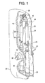
- FIG. 1 is a schematic, partial cross sectional view, with parts cut away, of a reactor pressure vessel (RPV) 20 for a boiling water reactor.
- the RPV 20 has a generally cylindrical-shape and is closed at one end by a bottom head and at its other end by removable top head (not shown).
- a top guide (not shown) is situated above a core plate 22 within RPV 20.
- a shroud 24 surrounds core plate 22 and is supported by a shroud support structure 26.
- a downcomer annulus 28 is formed between the shroud 24 and a sidewall 30 of RPV 20.
- An annulet nozzle 32 extends through sidewall 30 of the RPV 20 and is coupled to a jet pump assembly 34.
- the jet pump assembly 34 includes a thermal sleeve 36 which extends through nozzle 32, a lower elbow (only partially visible in FIG. 1), and an inlet riser pipe 38 coupled to a pair of jet pumps 35.
- Thermal sleeve 36 is secured at a first end (not shown) to a second end of the lower elbow.
- the first end of thermal sleeve 36 is welded to the second end of the lower elbow.
- a first end of the lower elbow is similarly secured or welded to one end of the riser pipe 38.
- the riser pipe 38 extends between and substantially parallel to the shroud 24 and sidewall 30.
- the jet pumps 35 are circumferentially distributed around the core shroud 24.
- the riser pipe 38 is coupled to the two jet pumps 35 by a transition assembly 39.
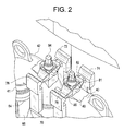
- FIG. 2 is a perspective view of a jet pump assembly.
- Each jet pump 35 includes a jet pump nozzle 64, a suction inlet 66, an inlet mixer 41, and a diffuser 42.
- the jet pump nozzle 64 may be positioned in the suction inlet 66 which may be located at a first end (not shown) of inlet mixer 41.
- the transition assembly 39 may include a base piece 70 and two elbows. Each elbow is coupled to a jet pump nozzle 64. Locking arms 72, 74, 76, and 78 extend from the transition assembly base piece 70.
- a jet pump beam 86 is connected between the locking arms 72, 74, 76 and 78.
- One jet pump beam 86 is engaged to a pair of support arms 72 and 76, and another jet pump beam 86 is engaged to a pair of support arms 74 and 78, as shown in FIG. 2.
- Each jet pump beam 86 includes a tongue member 81 at an end thereof which engages notches 82 in the locking arms 72, 74, 76 and 78 for preventing and/or reducing movement (e.g., rotational) of a corresponding beam bolt 94.
- the jet pump beams 86 engage locking arms 72, 74, 76 and 78 by sliding the tongue member 81 into the notches 82.
- the jet pump beams 86 are generally attached to the inlet mixer 41 by a retainer plate (not shown) which is locked to the inlet mixer 41 with a retainer bolt.
- a retainer plate (not shown) which is locked to the inlet mixer 41 with a retainer bolt.
- tack welds are applied to prevent the bolt 94 from vibrating loose.
- jet pump beam assemblies occasional need to be repaired or replaced.
- the entire inlet mixer 41 is removed and moved into an open area to allow better access to separate the jet pump beam assembly from the inlet mixer 41 (e.g., by breaking the tack welds, removing the bolt and removing the retainer plate).
- this procedure is time consuming, labor intensive and requires additional equipment on-site.
- torque multipliers are bulky and large, and thus cannot fit in the area of the jet pump beams.
- An exemplary embodiment of the present invention is directed to an electrical discharge machining (EDM) tool for removing tack welds from surfaces of reactor pressure vessel components.
- the tool may include a motor, a housing which engages a retainer bolt having tack welds, a moveable electrode plate positioned in the housing, a first plate, and a second plate attached to the electrode.
- the second plate actuates to align the electrode plate to the tack weld.
- the electrode plate electrically discharges electrodes to remove tack welds from the components.
- EDM electrical discharge machining
- FIG. 3 is a schematic view of an EDM tool 100 operable on a jet pump beam bolt in accordance with an exemplary embodiment of the invention. It is appreciated that the portion of the jet pump assembly 34 shown in FIG. 3 is similar to FIG. 2, and will not be described in detail.
- the jet pump beams 86 are attached to the inlet mixer 41.
- a retainer plate 52 for supporting the jet pump beams 86 is attached below the beams 86.
- the plate 52 includes an opening which aligns with an opening on a block 49. Once aligned, a retainer bolt 90 may be inserted for fastening the retainer plate 52 to the inlet mixer 41.
- the retainer bolt 90 may include tack welds 91 for reinforcing the retainer bolt 90.
- the tack welds 91 are secured to the retainer plate 52 in a conventional manner using known welding processes.
- the EDM tool 100 engages the retainer bolt 90.
- the tool 100 is generally elongated (or linear) in shape so as to engage the retainer bolt 90. Due to the design and operability of the tool 100, the EDM tool 100 may easily maneuver around the area of the jet pump assembly 34.
- the tool 100 includes a bolt housing 110 for engaging (or indexing off) a surface of the bolt head 90.
- the surface of the bolt head 90 may be hexagonal and thus the housing may assume a complimentary hexagonal shape.
- other shapes of the bolt head 90 may be used, so long as the bolt housing 110 corresponds to the shape of the bolt head 90.
- the bolt housing 110 is attached to a support frame plate 120 extending from the housing 110 as shown in FIG. 3.
- the design of the support frame plate 120 may be construed as a generally narrow, extended linear slide shape.
- the support frame plate 120 is generally planar extending from the housing 110, and includes a gap 121 at an opposite end thereof.
- the gap 121 is designed to encompass ball screw nut 135.
- a platform 125 is formed on top of opening 121 for holding an EDM motor 140.
- the motor 140 may be attached to the platform 125 with fasteners 128, i.e., screws or any other equivalent attachment means.
- the motor 140 can be a conventional DC stepper that is typically used in EDM applications.
- the motor 140 includes an extending wire 161 thereto for supplying power. As shown in FIG. 3, the wire 161 includes a connector 165 for connecting to a power supply (not shown).
- the support frame plate 120 and the platform 125 may be made from stainless steel. However, it should be appreciated that other materials such as aluminum may be employed. It should further be appreciated that the support frame plate 120 and platform 125 may be formed as a unitary piece or as separate components fastened together.
- An actuating plate 130 (which parallels plate 120) extends into the housing 110. As will be described in detail later, the actuating plate 130 is used to engage an electrode which will be energized to release tack welds 90.
- the actuating plate 130 is attached to an electrode plate 150 (shown in FIG. 5) in the housing 110.
- the actuating plate 130 provides the movement for engaging the electrode plate 150 to the bolt head 90 and electrically discharging the electrodes for removal of the tack welds 91.
- the electrode plate 150 may be made from graphite or silver tungsten, and/or materials having equivalent conductive properties.
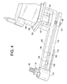
- FIG. 4 is a detailed schematic view of an EDM tool 100 of FIG. 3 in further detail.
- FIG. 4 shows the tool 100 without the surrounding jet pump assembly components.
- the tool 100 may include a bolt housing 110, a support frame plate 120, an actuating plate 130, a ball screw nut 135, a motor 140, and an electrode plate 150.
- the housing 110 engages the retainer bolt 90 for removing the tack welds 91.
- the motor 140 operates via the ball screw nut 135 to move (retract and extend) the electrode plate 150 located in the housing 110.
- the ball screw nut 135 rotates a ball screw 160 to move the plate 130 which then ultimately moves the electrode plate 150 a distance of approximately one inch.
- An extension piece 170 extending from the bottom of the housing 110 prevents the actuating plate 130 from moving out of the ball screw 160 (e.g., acts as a stop piece).
- the extension piece 170 may be made from the same material as the plate 120 and/or supports 139.
- the actuating plate 130 may include at least three holes 131, 132 and 133. Hole 131 receives a ball screw 160 extending from the ball screw nut 135; and holes 132 and 133 receive supports 139 extending from the plate 120.
- the supports 139 may provide structural support for reinforcement, and may also be used for linear guides (e.g., when the actuating plate 130 is moving).
- the supports 139 may be made from the same material as the support frame plate 120.
- the actuating plate 130 may be made from the same material as the support frame plate 120, for example.
- the housing 110 includes index members 112 (shown in FIGS. 5A and 5B) which correspond to the shape of the bolt head 90.
- the index members 112 allow alignment to, for example, a hexagonal bolt head 90. This assures proper alignment to the welds.
- two index members 112 extend inwardly in the housing 110 to receive the retainer bolt 90. It should be appreciated that more than two index members 112 may be used in the housing 110. It should further be appreciated that other design of the index member 112 may be implemented.
- the housing 110 includes an indent 117 at a top end thereof to facilitate the insertion of the retainer bolt 90 into the housing 110.
- the electrode 150 may retract and extend in the housing 110.
- the electrode plate 150 is in the retracted position (shown in FIG. 5A).
- the electrode plate 150 is in the extended position (shown in FIG. 5B). In the extended position, the electrodes are discharged to remove the tack weld 91.
- FIG. 5B illustrates the retainer bolt 90 with the tack welds 91 removed (e.g., reference character 91a indicates where welds 91 previously were located).
- the electrode 150 retracts to disengage from the retainer bolt 90.
Landscapes
- Engineering & Computer Science (AREA)
- Mechanical Engineering (AREA)
- Chemical & Material Sciences (AREA)
- Chemical Kinetics & Catalysis (AREA)
- Electrochemistry (AREA)
- Physics & Mathematics (AREA)
- Thermal Sciences (AREA)
- Manufacturing & Machinery (AREA)
- Electrical Discharge Machining, Electrochemical Machining, And Combined Machining (AREA)
- Arc Welding In General (AREA)
- Jet Pumps And Other Pumps (AREA)
Abstract
An electrical discharge machining (EDM) tool and method for removing tack welds on a component in a reactor pressure vessel are disclosed. The tool may include a motor (140), a housing (110) which engages the component having tack welds, an electrode, positioned in the housing, a first plate (120), and a second plate (130) attached to the electrode. The second plate (130) actuates to align the electrode to the tack weld, and the electrode is discharged to remove the tack welds from the component.
Description
- This invention relates generally to a method and apparatus tack welds on reactor vessel components via electro-discharge machining (EDM).
- Electrical Discharge Machining (EDM) is a common technique used for machining hard metals or those that would be impossible to machine with traditional techniques. EDM may be well-suited for cutting intricate contours or delicate cavities that would be difficult to produce with a grinder, an end mill or other cutting tools. EDM removes metal by producing a rapid series of repetitive electrical discharges. These electrical discharges are passes between an electrode and the piece of metal being machined. The repetitive discharges may remove the unwanted metal or create a set of successively deeper craters in the metal until a final shape is produced. Because EDM works with materials that are electrically conductive, metals that can be machined may include, for example, but not limited to, hastalloy, hardened tool-steel, titanium, carbide, inconel and kovar.
- EDM is used to machine metals in a reactor pressure vessel (RPV) of a boiling water reactor (BWR). A typical reactor pressure vessel at a BWR has a generally cylindrical shape and is closed at both ends, e.g., by a bottom head and a removable top head. A top guide typically is spaced above a core plate within the RPV. A core shroud, or shroud, typically surrounds the core and is supported by a shroud support structure. Particularly, the shroud has a generally cylindrical shape and surrounds both the core plate and the top guide. There is a space or annulus located between the cylindrical reactor pressure vessel and the cylindrically-shaped shroud.
- FIG. 1 is a schematic, partial cross sectional view, with parts cut away, of a reactor pressure vessel (RPV) 20 for a boiling water reactor. The
RPV 20 has a generally cylindrical-shape and is closed at one end by a bottom head and at its other end by removable top head (not shown). A top guide (not shown) is situated above acore plate 22 withinRPV 20. A shroud 24surrounds core plate 22 and is supported by ashroud support structure 26. Adowncomer annulus 28 is formed between theshroud 24 and asidewall 30 of RPV 20. - An
annulet nozzle 32 extends throughsidewall 30 of theRPV 20 and is coupled to ajet pump assembly 34. Thejet pump assembly 34 includes athermal sleeve 36 which extends throughnozzle 32, a lower elbow (only partially visible in FIG. 1), and aninlet riser pipe 38 coupled to a pair ofjet pumps 35.Thermal sleeve 36 is secured at a first end (not shown) to a second end of the lower elbow. The first end ofthermal sleeve 36 is welded to the second end of the lower elbow. A first end of the lower elbow is similarly secured or welded to one end of theriser pipe 38. Theriser pipe 38 extends between and substantially parallel to theshroud 24 andsidewall 30. Thejet pumps 35 are circumferentially distributed around thecore shroud 24. Theriser pipe 38 is coupled to the twojet pumps 35 by atransition assembly 39. - FIG. 2 is a perspective view of a jet pump assembly. Each
jet pump 35 includes ajet pump nozzle 64, asuction inlet 66, aninlet mixer 41, and adiffuser 42. Thejet pump nozzle 64 may be positioned in thesuction inlet 66 which may be located at a first end (not shown) ofinlet mixer 41. Thetransition assembly 39 may include abase piece 70 and two elbows. Each elbow is coupled to ajet pump nozzle 64. Lockingarms assembly base piece 70. Ajet pump beam 86 is connected between the lockingarms jet pump beam 86 is engaged to a pair ofsupport arms jet pump beam 86 is engaged to a pair ofsupport arms jet pump beam 86 includes atongue member 81 at an end thereof which engagesnotches 82 in the lockingarms corresponding beam bolt 94. Thejet pump beams 86 engage lockingarms tongue member 81 into thenotches 82. - The
jet pump beams 86 are generally attached to theinlet mixer 41 by a retainer plate (not shown) which is locked to theinlet mixer 41 with a retainer bolt. To lock thebeam bolt 94, tack welds are applied to prevent thebolt 94 from vibrating loose. However, jet pump beam assemblies occasional need to be repaired or replaced. - Thus, in order to repair/replace the jet pump beam assembly, the
entire inlet mixer 41 is removed and moved into an open area to allow better access to separate the jet pump beam assembly from the inlet mixer 41 (e.g., by breaking the tack welds, removing the bolt and removing the retainer plate). However, this procedure is time consuming, labor intensive and requires additional equipment on-site. - Other techniques of breaking the tack welds and removing the jet pump retainer bolt use a torque multiplier to remove the tack welds. However, torque multipliers are bulky and large, and thus cannot fit in the area of the jet pump beams.
- An exemplary embodiment of the present invention is directed to an electrical discharge machining (EDM) tool for removing tack welds from surfaces of reactor pressure vessel components. The tool may include a motor, a housing which engages a retainer bolt having tack welds, a moveable electrode plate positioned in the housing, a first plate, and a second plate attached to the electrode.
- In a further exemplary embodiment, the second plate actuates to align the electrode plate to the tack weld.
- In yet a further exemplary embodiment, the electrode plate electrically discharges electrodes to remove tack welds from the components.
- Another exemplary embodiment of the present invention is directed to a method of removing tack welds by electrical discharge machining (EDM). In the method, an EDM tool is installed over a component. The tool includes a housing, a first plate, a second plate and an electrode plate. The second plate is actuated to move the electrode in the housing. The , electrode plate electrically discharges electrodes to remove the tack welds. The EDM tool is then removed from the component.
- The present invention will become more fully understood from the detailed description given herein below and the accompanying drawings, wherein like elements are represented by like reference numerals, which are given by way of illustration only and thus are not limitative of the present invention.
- FIG. 1 is a schematic, partial cross-sectional view, with parts cut away, of a reactor pressure vessel (RPV) of a boiling water nuclear reactor.
- FIG. 2 illustrates a riser brace assembly in accordance with an exemplary embodiment of the invention.
- FIG. 3 is a schematic view of an EDM tool operable on a jet pump beam bolt in accordance with an exemplary embodiment of the invention.
- FIG. 4 is a detailed schematic view of the EDM tool as shown in FIG 3.
- FIG. 5A and 5B are detailed schematic views of a head of the EDM tool in accordance with an exemplary embodiment of the invention.
- These figures are intended to illustrate the general characteristics of method and apparatus of exemplary embodiments of this invention, for the purpose of the description of such exemplary embodiments herein. These drawings are not, however, to scale and may not precisely reflect the characteristics of any given embodiment, and should not be interpreted as defining or limiting the range of values or properties of exemplary embodiments within the scope of this invention. The relative dimensions and size of the jet pump assembly may be reduced or exaggerated for clarity. Like numerals are used for like and corresponding parts of the various drawings.
- FIG. 3 is a schematic view of an
EDM tool 100 operable on a jet pump beam bolt in accordance with an exemplary embodiment of the invention. It is appreciated that the portion of thejet pump assembly 34 shown in FIG. 3 is similar to FIG. 2, and will not be described in detail. - Referring to FIG. 3, the jet pump beams 86 are attached to the
inlet mixer 41. Aretainer plate 52 for supporting the jet pump beams 86 is attached below thebeams 86. Theplate 52 includes an opening which aligns with an opening on ablock 49. Once aligned, aretainer bolt 90 may be inserted for fastening theretainer plate 52 to theinlet mixer 41. Theretainer bolt 90 may include tack welds 91 for reinforcing theretainer bolt 90. The tack welds 91 are secured to theretainer plate 52 in a conventional manner using known welding processes. - The
EDM tool 100 engages theretainer bolt 90. Thetool 100 is generally elongated (or linear) in shape so as to engage theretainer bolt 90. Due to the design and operability of thetool 100, theEDM tool 100 may easily maneuver around the area of thejet pump assembly 34. - The
tool 100 includes abolt housing 110 for engaging (or indexing off) a surface of thebolt head 90. In an example, the surface of thebolt head 90 may be hexagonal and thus the housing may assume a complimentary hexagonal shape. However, it should be appreciated that other shapes of thebolt head 90 may be used, so long as thebolt housing 110 corresponds to the shape of thebolt head 90. - The
bolt housing 110 is attached to asupport frame plate 120 extending from thehousing 110 as shown in FIG. 3. The design of thesupport frame plate 120 may be construed as a generally narrow, extended linear slide shape. Thesupport frame plate 120 is generally planar extending from thehousing 110, and includes agap 121 at an opposite end thereof. Thegap 121 is designed to encompassball screw nut 135. Aplatform 125 is formed on top of opening 121 for holding anEDM motor 140. Themotor 140 may be attached to theplatform 125 withfasteners 128, i.e., screws or any other equivalent attachment means. Themotor 140 can be a conventional DC stepper that is typically used in EDM applications. Themotor 140 includes an extendingwire 161 thereto for supplying power. As shown in FIG. 3, thewire 161 includes aconnector 165 for connecting to a power supply (not shown). - As an example, the
support frame plate 120 and theplatform 125 may be made from stainless steel. However, it should be appreciated that other materials such as aluminum may be employed. It should further be appreciated that thesupport frame plate 120 andplatform 125 may be formed as a unitary piece or as separate components fastened together. - An actuating plate 130 (which parallels plate 120) extends into the
housing 110. As will be described in detail later, theactuating plate 130 is used to engage an electrode which will be energized to release tack welds 90. - The
actuating plate 130 is attached to an electrode plate 150 (shown in FIG. 5) in thehousing 110. Theactuating plate 130 provides the movement for engaging theelectrode plate 150 to thebolt head 90 and electrically discharging the electrodes for removal of the tack welds 91. Theelectrode plate 150 may be made from graphite or silver tungsten, and/or materials having equivalent conductive properties. - FIG. 4 is a detailed schematic view of an
EDM tool 100 of FIG. 3 in further detail. - FIG. 4 shows the
tool 100 without the surrounding jet pump assembly components. Thetool 100 may include abolt housing 110, asupport frame plate 120, anactuating plate 130, aball screw nut 135, amotor 140, and anelectrode plate 150. - The
housing 110 engages theretainer bolt 90 for removing the tack welds 91. When thehousing 110 is installed on theretainer bolt 90, themotor 140 operates via theball screw nut 135 to move (retract and extend) theelectrode plate 150 located in thehousing 110. Theball screw nut 135 rotates aball screw 160 to move theplate 130 which then ultimately moves the electrode plate 150 a distance of approximately one inch. Anextension piece 170 extending from the bottom of thehousing 110 prevents theactuating plate 130 from moving out of the ball screw 160 (e.g., acts as a stop piece). Theextension piece 170 may be made from the same material as theplate 120 and/or supports 139. - The
actuating plate 130 may include at least threeholes Hole 131 receives aball screw 160 extending from theball screw nut 135; and holes 132 and 133 receivesupports 139 extending from theplate 120. Thesupports 139 may provide structural support for reinforcement, and may also be used for linear guides (e.g., when theactuating plate 130 is moving). Thesupports 139 may be made from the same material as thesupport frame plate 120. Theactuating plate 130 may be made from the same material as thesupport frame plate 120, for example. - The
housing 110 includes index members 112 (shown in FIGS. 5A and 5B) which correspond to the shape of thebolt head 90. Theindex members 112 allow alignment to, for example, ahexagonal bolt head 90. This assures proper alignment to the welds. As an exemplary embodiment, twoindex members 112 extend inwardly in thehousing 110 to receive theretainer bolt 90. It should be appreciated that more than twoindex members 112 may be used in thehousing 110. It should further be appreciated that other design of theindex member 112 may be implemented. Thehousing 110 includes anindent 117 at a top end thereof to facilitate the insertion of theretainer bolt 90 into thehousing 110. - As discussed above, the
electrode 150 may retract and extend in thehousing 110. During the placing of thehousing 110 onto theretainer bolt 90, theelectrode plate 150 is in the retracted position (shown in FIG. 5A). During the removal of thetack weld 91, theelectrode plate 150 is in the extended position (shown in FIG. 5B). In the extended position, the electrodes are discharged to remove thetack weld 91. FIG. 5B illustrates theretainer bolt 90 with the tack welds 91 removed (e.g.,reference character 91a indicates where welds 91 previously were located). Upon the removal of theEDM tool 100, theelectrode 150 retracts to disengage from theretainer bolt 90. Once the tack welds 91 are consumed by the discharging of theelectrode 150 and theEDM tool 100 is removed from the work area, theretainer bolt 90 is removed by a standard low profile right angle nut runner. Since the tack welds 91 are no longer present, the bolt removal torque is low. The invention being thus described, it will be obvious that the same may be varied in many ways. Such variations are not to be regarded as departure from the spirit and scope of the invention, and all such modifications as would be obvious to one skilled in the art are intended to be included within the scope of the following claims.
Claims (16)
- A electrical discharge machining (EDM) tool for removing tack welds from surfaces of reactor pressure vessel components, comprising:a motor;a housing which engages a retainer bolt having tack welds;a moveable electrode plate positioned in the housing;a first plate; anda second plate attached to the electrode plate,wherein the second plate actuates to align the electrode plate to the tack weld, the electrode plate electrically discharging electrodes to remove the tack welds from retainer bolt.
- The EDM tool according to claim 1, further comprising a ball screw rotatable by a ball screw nut for actuating the second plate.
- The EDM tool according to claim 2, wherein the ball screw nut on the first plate.
- The EDM tool according to claim 1, wherein the housing includes a pair of index members, for receiving the retainer bolt.
- The EDM tool according to claim 4, wherein the index members are positioned inwardly toward a center of the housing.
- The EDM tool according to claim 1, wherein the housing includes an indent for facilitating insertion of the retainer bolt into the housing.
- The EDM tool according to claim 1, wherein the electrode plate is made from graphite or silver tungsten.
- The EDM tool according to claim 1, wherein the electrode plate retracts within the housing during insertion of the retainer bolt and removal of the retainer bolt.
- The EDM tool according to claim 1, wherein the electrode plate extends within the housing during removal of the tack welds.
- The EDM tool according to claim 1, wherein the first plate includes support members for guiding the second plate.
- The EDM tool according to claim 1, wherein the first and second plates are made from stainless steel or aluminum.
- A method of removing tack welds from a reactor pressure vessel component by electrical discharge machining (EDM), comprising:placing an EDM tool over the component, the tool including a housing, a first plate, a second plate and an electrode plate;actuating the second plate to move the electrode plate in the housing;electrically discharging electrodes to remove the tack welds from the component; andremoving the EDM tool from the component.
- The method of claim 12, wherein the second plate is actuated by a ball screw.
- The method according to claim 12, further comprising retracting the electrode plate in the housing during placement of the EDM tool over the component.
- The method according to claim 12, further comprising extending the electrode plate in the housing during consumption of the tack weld.
- The method according to claim 12, further comprising retracting the electrode plate in the housing during removal of the EDM tool.
Applications Claiming Priority (1)
| Application Number | Priority Date | Filing Date | Title |
|---|---|---|---|
| US11/342,561 US7889827B2 (en) | 2006-01-31 | 2006-01-31 | Method and apparatus for removing tack welds on reactor vessel components in a nuclear reactor |
Publications (1)
| Publication Number | Publication Date |
|---|---|
| EP1813373A2 true EP1813373A2 (en) | 2007-08-01 |
Family
ID=38080872
Family Applications (1)
| Application Number | Title | Priority Date | Filing Date |
|---|---|---|---|
| EP07101339A Withdrawn EP1813373A2 (en) | 2006-01-31 | 2007-01-29 | Method and apparatus for removing tack welds on reactor vessel components in a nuclear reactor |
Country Status (5)
| Country | Link |
|---|---|
| US (1) | US7889827B2 (en) |
| EP (1) | EP1813373A2 (en) |
| JP (1) | JP2007206064A (en) |
| MX (1) | MX2007001218A (en) |
| TW (1) | TW200746174A (en) |
Families Citing this family (5)
| Publication number | Priority date | Publication date | Assignee | Title |
|---|---|---|---|---|
| WO2009113360A1 (en) * | 2008-03-10 | 2009-09-17 | 本田技研工業株式会社 | Door removing system and door removing method |
| TWI467595B (en) * | 2011-02-25 | 2015-01-01 | Areva Np Inc | Vibration reduction techniques for jet pump slip joints |
| US20140079468A1 (en) * | 2012-09-20 | 2014-03-20 | Areva Np Inc. | Jet Pump Stabilizer |
| KR101547765B1 (en) | 2014-04-30 | 2015-08-26 | 한전케이피에스 주식회사 | Changing device of bolt for inside of nuclear reactor |
| CN115488549B (en) * | 2022-09-06 | 2024-07-23 | 石家庄石一水泵制造有限公司 | Rotary type surfacing device for repairing energy-saving pump |
Family Cites Families (14)
| Publication number | Priority date | Publication date | Assignee | Title |
|---|---|---|---|---|
| US4337385A (en) * | 1977-05-11 | 1982-06-29 | Uti Corporation | Orbital tool support system for EDM machines and other machine tools |
| CH621077A5 (en) * | 1978-06-01 | 1981-01-15 | Charmilles Sa Ateliers | |
| JPS58149131A (en) * | 1982-02-25 | 1983-09-05 | Inoue Japax Res Inc | Electrospark machining apparatus |
| FR2554373B1 (en) * | 1983-11-04 | 1986-03-28 | Framatome Sa | SPARKING MACHINING DEVICE |
| US4690593A (en) * | 1986-01-24 | 1987-09-01 | Westinghouse Electric Corp. | Tool for cutting locking cups from guide tube mounting screws in a nuclear reactor |
| US5070589A (en) * | 1989-02-08 | 1991-12-10 | Westinghouse Electric Corp. | Process for servicing a jet pump hold down beam in a nuclear reactor |
| FR2682803B1 (en) * | 1991-10-21 | 1993-12-03 | Framatome | PROCESS AND DEVICE FOR TAKING A TEST PIECE IN THE TANK OF A NUCLEAR REACTOR IN DEFINITIVE STOP. |
| US5687205A (en) * | 1995-09-15 | 1997-11-11 | General Electric Company | Underwater remote drilling tool and methods |
| JP2000027538A (en) * | 1998-07-09 | 2000-01-25 | Komurakkusu:Kk | Door frame |
| US6233301B1 (en) * | 1998-09-25 | 2001-05-15 | General Electric Company | Jet pump sensing line T-bolt clamp electrode discharge machining tool |
| JP2000275382A (en) * | 1999-03-26 | 2000-10-06 | Toshiba Corp | Tightening bolt weld removal device |
| JP3725129B2 (en) * | 2003-02-25 | 2005-12-07 | ファナック株式会社 | Automatic tool tip changer for robot |
| US20040190671A1 (en) * | 2003-03-26 | 2004-09-30 | Wivagg Adrian P. | Jet pump assembly repair method |
| CN100411795C (en) * | 2004-05-13 | 2008-08-20 | 嘉昇机电工业股份有限公司 | Automatic electrode replacing device for fine hole electric discharge machine |
-
2006
- 2006-01-31 US US11/342,561 patent/US7889827B2/en not_active Expired - Fee Related
-
2007
- 2007-01-18 TW TW096101946A patent/TW200746174A/en unknown
- 2007-01-24 JP JP2007013848A patent/JP2007206064A/en not_active Withdrawn
- 2007-01-29 EP EP07101339A patent/EP1813373A2/en not_active Withdrawn
- 2007-01-30 MX MX2007001218A patent/MX2007001218A/en unknown
Also Published As
| Publication number | Publication date |
|---|---|
| US20070177708A1 (en) | 2007-08-02 |
| TW200746174A (en) | 2007-12-16 |
| JP2007206064A (en) | 2007-08-16 |
| US7889827B2 (en) | 2011-02-15 |
| MX2007001218A (en) | 2008-11-14 |
Similar Documents
| Publication | Publication Date | Title |
|---|---|---|
| EP1813373A2 (en) | Method and apparatus for removing tack welds on reactor vessel components in a nuclear reactor | |
| EP2255914B1 (en) | Support Element for a Work or Cutting Bench for a Cutting Device | |
| BRPI0800180B1 (en) | Plasma torch component, method for aligning a first component in a plasma torch assembly, plasma torch component set and method for aligning a first component and a second component of a plasma torch assembly | |
| EP1524059B1 (en) | An apparatus and method for machining in confined spaces | |
| EP2246139B1 (en) | A method of securing a workpiece for machining a trailing edge thereof, the workpiece being a vane or blade for a turbine engine. | |
| Bucklow et al. | Spark-machining | |
| EP1219880B1 (en) | Pipe support with spring loaded wedges | |
| EP1987915B1 (en) | Apparatus for fabricating a plurality of turbine components | |
| US5867550A (en) | Process for the production of a screen plate for a fuel assembly foot and corresponding fuel assembly | |
| DE602004010478T2 (en) | Method of electric discharge drilling | |
| US5618450A (en) | Tool having interchangeable indicia marking electrodes for use in electrical discharge machining | |
| RU2109353C1 (en) | Method and device for cutting nuclear plant components into fragments by spalling | |
| KR100712369B1 (en) | Electrode Fixation Jig for Milling | |
| JPH052280B2 (en) | ||
| CN118544135B (en) | A multi-energy field composite drilling and milling processing tool and processing method | |
| EP0594381B1 (en) | Control blade servicing assembly | |
| US4239246A (en) | Rigid chuck assembly | |
| CN220993034U (en) | Pore discharge machine convenient to location | |
| EP2727677A1 (en) | Method for dressing at least one eroding electrode and dressing system | |
| US12569923B1 (en) | Micro-electric discharge milling machine with spark control | |
| JP4349868B2 (en) | Broach and broach device | |
| CN219093824U (en) | Assembled alloy chamfer tooth modularization keyway broach | |
| CN223368362U (en) | Split type nut inserting piece groove processing device | |
| CN112916967B (en) | Variable-pitch quick-changing tool holder type thread milling cutter | |
| KR100558617B1 (en) | Counterbore Forming Method Using Counter End Mill |
Legal Events
| Date | Code | Title | Description |
|---|---|---|---|
| PUAI | Public reference made under article 153(3) epc to a published international application that has entered the european phase |
Free format text: ORIGINAL CODE: 0009012 |
|
| AK | Designated contracting states |
Kind code of ref document: A2 Designated state(s): AT BE BG CH CY CZ DE DK EE ES FI FR GB GR HU IE IS IT LI LT LU LV MC NL PL PT RO SE SI SK TR |
|
| AX | Request for extension of the european patent |
Extension state: AL BA HR MK YU |
|
| STAA | Information on the status of an ep patent application or granted ep patent |
Free format text: STATUS: THE APPLICATION IS DEEMED TO BE WITHDRAWN |
|
| 18D | Application deemed to be withdrawn |
Effective date: 20100803 |