EP1813193A2 - Apparatus and method for displaying an ultrasound image - Google Patents
Apparatus and method for displaying an ultrasound image Download PDFInfo
- Publication number
- EP1813193A2 EP1813193A2 EP07001368A EP07001368A EP1813193A2 EP 1813193 A2 EP1813193 A2 EP 1813193A2 EP 07001368 A EP07001368 A EP 07001368A EP 07001368 A EP07001368 A EP 07001368A EP 1813193 A2 EP1813193 A2 EP 1813193A2
- Authority
- EP
- European Patent Office
- Prior art keywords
- dimensional ultrasound
- ultrasound image
- cycle
- dimensional
- images
- Prior art date
- Legal status (The legal status is an assumption and is not a legal conclusion. Google has not performed a legal analysis and makes no representation as to the accuracy of the status listed.)
- Ceased
Links
Images





Classifications
-
- A—HUMAN NECESSITIES
- A45—HAND OR TRAVELLING ARTICLES
- A45B—WALKING STICKS; UMBRELLAS; LADIES' OR LIKE FANS
- A45B3/00—Sticks combined with other objects
-
- A—HUMAN NECESSITIES
- A61—MEDICAL OR VETERINARY SCIENCE; HYGIENE
- A61B—DIAGNOSIS; SURGERY; IDENTIFICATION
- A61B8/00—Diagnosis using ultrasonic, sonic or infrasonic waves
- A61B8/08—Clinical applications
-
- A—HUMAN NECESSITIES
- A45—HAND OR TRAVELLING ARTICLES
- A45B—WALKING STICKS; UMBRELLAS; LADIES' OR LIKE FANS
- A45B9/00—Details
- A45B9/02—Handles or heads
-
- A—HUMAN NECESSITIES
- A45—HAND OR TRAVELLING ARTICLES
- A45B—WALKING STICKS; UMBRELLAS; LADIES' OR LIKE FANS
- A45B9/00—Details
- A45B9/04—Ferrules or tips
-
- A—HUMAN NECESSITIES
- A61—MEDICAL OR VETERINARY SCIENCE; HYGIENE
- A61B—DIAGNOSIS; SURGERY; IDENTIFICATION
- A61B8/00—Diagnosis using ultrasonic, sonic or infrasonic waves
- A61B8/48—Diagnostic techniques
- A61B8/483—Diagnostic techniques involving the acquisition of a 3D volume of data
-
- F—MECHANICAL ENGINEERING; LIGHTING; HEATING; WEAPONS; BLASTING
- F21—LIGHTING
- F21V—FUNCTIONAL FEATURES OR DETAILS OF LIGHTING DEVICES OR SYSTEMS THEREOF; STRUCTURAL COMBINATIONS OF LIGHTING DEVICES WITH OTHER ARTICLES, NOT OTHERWISE PROVIDED FOR
- F21V23/00—Arrangement of electric circuit elements in or on lighting devices
- F21V23/04—Arrangement of electric circuit elements in or on lighting devices the elements being switches
-
- F—MECHANICAL ENGINEERING; LIGHTING; HEATING; WEAPONS; BLASTING
- F21—LIGHTING
- F21V—FUNCTIONAL FEATURES OR DETAILS OF LIGHTING DEVICES OR SYSTEMS THEREOF; STRUCTURAL COMBINATIONS OF LIGHTING DEVICES WITH OTHER ARTICLES, NOT OTHERWISE PROVIDED FOR
- F21V33/00—Structural combinations of lighting devices with other articles, not otherwise provided for
- F21V33/0004—Personal or domestic articles
-
- G—PHYSICS
- G01—MEASURING; TESTING
- G01S—RADIO DIRECTION-FINDING; RADIO NAVIGATION; DETERMINING DISTANCE OR VELOCITY BY USE OF RADIO WAVES; LOCATING OR PRESENCE-DETECTING BY USE OF THE REFLECTION OR RERADIATION OF RADIO WAVES; ANALOGOUS ARRANGEMENTS USING OTHER WAVES
- G01S15/00—Systems using the reflection or reradiation of acoustic waves, e.g. sonar systems
- G01S15/88—Sonar systems specially adapted for specific applications
- G01S15/89—Sonar systems specially adapted for specific applications for mapping or imaging
- G01S15/8906—Short-range imaging systems; Acoustic microscope systems using pulse-echo techniques
- G01S15/8993—Three dimensional imaging systems
-
- G—PHYSICS
- G01—MEASURING; TESTING
- G01S—RADIO DIRECTION-FINDING; RADIO NAVIGATION; DETERMINING DISTANCE OR VELOCITY BY USE OF RADIO WAVES; LOCATING OR PRESENCE-DETECTING BY USE OF THE REFLECTION OR RERADIATION OF RADIO WAVES; ANALOGOUS ARRANGEMENTS USING OTHER WAVES
- G01S7/00—Details of systems according to groups G01S13/00, G01S15/00, G01S17/00
- G01S7/52—Details of systems according to groups G01S13/00, G01S15/00, G01S17/00 of systems according to group G01S15/00
- G01S7/52017—Details of systems according to groups G01S13/00, G01S15/00, G01S17/00 of systems according to group G01S15/00 particularly adapted to short-range imaging
- G01S7/52085—Details related to the ultrasound signal acquisition, e.g. scan sequences
- G01S7/52087—Details related to the ultrasound signal acquisition, e.g. scan sequences using synchronization techniques
-
- A—HUMAN NECESSITIES
- A45—HAND OR TRAVELLING ARTICLES
- A45B—WALKING STICKS; UMBRELLAS; LADIES' OR LIKE FANS
- A45B2200/00—Details not otherwise provided for in A45B
- A45B2200/10—Umbrellas; Sunshades
- A45B2200/1009—Umbrellas; Sunshades combined with other objects
- A45B2200/1018—Umbrellas; Sunshades combined with other objects with illuminating devices, e.g. electrical
-
- A—HUMAN NECESSITIES
- A45—HAND OR TRAVELLING ARTICLES
- A45B—WALKING STICKS; UMBRELLAS; LADIES' OR LIKE FANS
- A45B2200/00—Details not otherwise provided for in A45B
- A45B2200/10—Umbrellas; Sunshades
- A45B2200/1009—Umbrellas; Sunshades combined with other objects
- A45B2200/1054—Umbrellas; Sunshades combined with other objects with containers for storing objects, e.g. box
-
- A—HUMAN NECESSITIES
- A61—MEDICAL OR VETERINARY SCIENCE; HYGIENE
- A61B—DIAGNOSIS; SURGERY; IDENTIFICATION
- A61B8/00—Diagnosis using ultrasonic, sonic or infrasonic waves
- A61B8/08—Clinical applications
- A61B8/0883—Clinical applications for diagnosis of the heart
-
- A—HUMAN NECESSITIES
- A61—MEDICAL OR VETERINARY SCIENCE; HYGIENE
- A61B—DIAGNOSIS; SURGERY; IDENTIFICATION
- A61B8/00—Diagnosis using ultrasonic, sonic or infrasonic waves
- A61B8/08—Clinical applications
- A61B8/0891—Clinical applications for diagnosis of blood vessels
-
- G—PHYSICS
- G01—MEASURING; TESTING
- G01S—RADIO DIRECTION-FINDING; RADIO NAVIGATION; DETERMINING DISTANCE OR VELOCITY BY USE OF RADIO WAVES; LOCATING OR PRESENCE-DETECTING BY USE OF THE REFLECTION OR RERADIATION OF RADIO WAVES; ANALOGOUS ARRANGEMENTS USING OTHER WAVES
- G01S7/00—Details of systems according to groups G01S13/00, G01S15/00, G01S17/00
- G01S7/52—Details of systems according to groups G01S13/00, G01S15/00, G01S17/00 of systems according to group G01S15/00
- G01S7/52017—Details of systems according to groups G01S13/00, G01S15/00, G01S17/00 of systems according to group G01S15/00 particularly adapted to short-range imaging
- G01S7/52053—Display arrangements
- G01S7/52057—Cathode ray tube displays
- G01S7/52073—Production of cursor lines, markers or indicia by electronic means
-
- Y—GENERAL TAGGING OF NEW TECHNOLOGICAL DEVELOPMENTS; GENERAL TAGGING OF CROSS-SECTIONAL TECHNOLOGIES SPANNING OVER SEVERAL SECTIONS OF THE IPC; TECHNICAL SUBJECTS COVERED BY FORMER USPC CROSS-REFERENCE ART COLLECTIONS [XRACs] AND DIGESTS
- Y10—TECHNICAL SUBJECTS COVERED BY FORMER USPC
- Y10S—TECHNICAL SUBJECTS COVERED BY FORMER USPC CROSS-REFERENCE ART COLLECTIONS [XRACs] AND DIGESTS
- Y10S135/00—Tent, canopy, umbrella, or cane
- Y10S135/91—Illuminated cane or umbrella
Definitions
- the present invention generally relates to ultrasound image processing, and more particularly to an apparatus and method for displaying a 3-dimensional ultrasound image formed based on 2-dimensional ultrasound images.
- An ultrasound diagnostic system has become an important and popular diagnostic tool since it has a wide range of applications. Specifically, due to its non-invasive and non-destructive nature, the ultrasound diagnostic system has been extensively used in the medical profession. Modern high-performance ultrasound diagnostic systems and techniques are commonly used to produce two or three-dimensional diagnostic images of internal features of an object (e.g., human organs).
- an object e.g., human organs
- the ultrasound diagnostic system generally uses a wide bandwidth transducer to transmit and receive ultrasound signals.
- the ultrasound diagnostic system forms images of human internal tissues by electrically exciting an acoustic transducer element or an array of acoustic transducer elements to generate ultrasound signals that travel into the body.
- the ultrasound signals produce ultrasound echo signals since they are reflected from body tissues, which appear as discontinuities to the propagating ultrasound signals.
- Various ultrasound echo signals return to the transducer element and are converted into electrical signals, which are amplified and processed to produce ultrasound data for an image of the tissues.
- the ultrasound diagnostic system is very important in the medical field since it provides physicians with real-time and high-resolution images of human internal features without the need for invasive observation techniques such as surgery.
- the ultrasound diagnostic system obtains raw 3D data (e.g., data on a coordinate system (x, y and z)) through a 3D probe by stacking consecutive frames. It then processes the consecutive frames by using a 3D rendering technique, thereby producing 3D static images.
- raw 3D data e.g., data on a coordinate system (x, y and z)
- 3D rendering technique e.g., 3D rendering technique
- the static 3D images are widely used.
- the static 3D images are not useful in observing a moving target object in real time, such as a fetus in the uterus.
- a live 3D imaging method and apparatus for providing a live 3D moving image have been developed.
- the live 3D image consists of fewer frames compared to a real-time 3D moving image.
- the live 3D image cannot completely represent the movement of a moving target object.
- the live 3D image consists of more frames than static 3D images (e.g., 2 to 4 frames per second), it can represent the movement of a moving target object more smoothly than the static 3D images.
- FIG. 1 is a schematic block diagram illustrating an ultrasound diagnostic device constructed in accordance with one embodiment of the present invention
- FIG. 2 is a schematic diagram illustrating an example of setting a cycle of an electrocardiogram signal
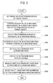
- FIG. 3 is a flowchart illustrating a method of displaying an ultrasound image in accordance with one embodiment of the present invention
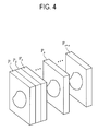
- FIG. 4 is a schematic diagram illustrating a plurality of 2-dimensional ultrasound images
- FIG. 5 is a schematic diagram illustrating a predetermined number of 2-dimensional ultrasound images for forming a 3-dimensional ultrasound image
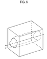
- FIG. 6 is a schematic diagram illustrating a 3-dimensional ultrasound image formed by superposing a predetermined number of 2-dimensional ultrasound images in accordance with one embodiment of the present invention
- FIG. 7 is a schematic diagram illustrating a 3-dimensional ultrasound image on which a plurality of ECG cycle markers are set
- FIG. 8 is a schematic diagram illustrating an updated 3-dimensional ultrasound image
- FIG. 9 is a schematic diagram illustrating an example of selecting two volumes in the 3-dimensional ultrasound image in accordance with one embodiment of the present invention.
- FIG. 1 is a block diagram illustrating an ultrasound diagnostic device, which is constructed in accordance with the present invention.
- the ultrasound diagnostic device 100 includes a probe 110, a 2-dimensional ultrasound image forming unit 120, a 3-dimensional ultrasound image forming unit 130, a display unit 140, a marker setting unit 150 and an electrocardiogram (ECG) signal cycle setting unit 160.
- the probe 110 transmits ultrasound signals to a predetermined region of a target object, which includes a periodically moving object, and receives ultrasound echo signals.
- the periodically moving object may be a heart, a blood vessel or the like.
- the probe 110 may be any type of probe, which is capable of acquiring a 2-dimensional ultrasound image.
- the 2-dimensional ultrasound image forming unit 120 forms a plurality of 2-dimensional ultrasound images based on the ultrasound echo signals according to time.
- the 2-dimensional ultrasound images may be stored in a memory (not denoted).
- the 2-dimensional ultrasound images are stored with forming time information.
- the "forming time” may refer to the time at which a 2-dimensional ultrasound image is formed in the 2-dimensional ultrasound image forming unit 120.
- the 2-dimensional ultrasound images may be B-mode images, Doppler images or color-mode images.
- the 3-dimensional ultrasound image forming unit 130 forms a 3-dimensional ultrasound image based on the multiple 2-dimensional ultrasound images.
- the 3-dimensional ultrasound image forming unit 130 selects a predetermined number of 2-dimensional ultrasound images and may store the selected 2-dimensional ultrasound images in a buffer.
- the 3-dimensional ultrasound image forming unit 130 superposes the stored 2-dimensional ultrasound images, thereby forming a 3-dimensional ultrasound image.
- the selected 2-dimensional ultrasound images may be individually rendered and then stored in the buffer.
- the 3-dimensional ultrasound image forming unit 130 may provide a transparent 3-dimensional ultrasound image obtained by an appropriate transparency treatment for showing a volume of interest (VOI) in the 3-dimensional ultrasound image.
- VOI volume of interest
- the 3-dimensional ultrasound image or the transparent 3-dimensional ultrasound image formed in the 3-dimensional ultrasound image forming unit 130 is transmitted to the display unit. It is then displayed on a screen of the display unit 140.
- the marker setting unit 150 sets a marker representing a cycle of a heartbeat on the 3-dimensional ultrasound image.
- the ECG cycle setting unit 160 analyzes an ECG signal inputted from an ECG measurement device (not denoted) during a predetermined time and sets an ECG cycle. As shown in Fig. 2, for example, an interval between neighboring peaks A1 and A2 on the ECG signal may be set as an ECG cycle. Alternatively, an interval of identical phases B1 and B2, which are repeated, may be set as an ECG cycle. Information of the ECG cycle set in the ECG cycle setting unit 160 is transmitted to the marker setting unit 150.
- Fig. 3 is a flowchart, which illustrates the method of displaying the ultrasound image in accordance with an embodiment of the present invention.
- the probe 110 is set on a predetermined portion of a surface of the target object to transmit ultrasound signals to a specific slice of a heart at step S310.
- the 2-dimensional ultrasound image forming unit 120 forms a plurality of 2-dimensional ultrasound images in real time based on the ultrasound echo signals, which are reflected from the specific slice of the heart (shown in Fig. 4) at step S320.
- Reference symbols P 1 - P n+m represent the order of forming time of the 2-dimensional ultrasound images.
- the 2-dimensional ultrasound images may be stored in the memory with information of the forming time.
- the 3-dimensional ultrasound image forming unit 130 selects a predetermined number (e.g., n numbers) of 2-dimensional ultrasound images P i - P n+i-1 , which are consecutive in the order of the forming time, among the multiple 2-dimensional ultrasound images. It then stores the selected 2-dimensional ultrasound images P; - P n+i-1 in a memory such as a buffer at step S330.
- the selected 2-dimensional ultrasound images may be individually rendered and then stored in the memory.
- the marker setting unit 150 sets ECG cycle markers M 1 - M n on the 3-dimensional ultrasound image based on the ECG cycle provided from the ECG cycle setting unit 160 at step S350.
- the marker setting unit 150 selects a 2-dimensional ultrasound image P i having a foremost forming time among the 2-dimensional ultrasound images, which are used to form the 3-dimensional ultrasound image.
- the marker setting unit 150 sets a reference ECG cycle marker M 1 on the selected 2-dimensional ultrasound image.
- the marker setting unit 150 repeatedly sets a plurality of ECG cycle markers M 2 - M n by referring to the ECG cycle on the 3-dimensional ultrasound image. This is so that the 3-dimensional ultrasound image, on which the ECG cycle markers are set, is displayed on the display unit 140 (shown in Fig. 7) at step S360.
- the 3-dimensional ultrasound image forming unit 130 removes a 2-dimensional ultrasound image P i from the 2-dimensional ultrasound images P i ⁇ P i+n-1 at step S370.
- the 3-dimensional ultrasound image forming unit 130 selects a 2-dimensional ultrasound image P i+n , which is next to the 2-dimensional ultrasound image P i+n-1 , among the formed 2-dimensional ultrasound images (shown in Fig. 8) at step S380.
- the selected 2-dimensional ultrasound image P i+n may be rendered.
- steps S340 to S380 are repeatedly carried out for the 2-dimensional ultrasound images formed in the 2-dimensional ultrasound image forming unit 120 so as to consecutively form the 3-dimensional ultrasound images in real time.
- the 3-dimensional ultrasound images are displayed on the display unit 140.
- An inversion mode may be applied to the 3-dimensional ultrasound image formed according to one embodiment of the present invention. This is so that the walls of blood vessels or a heart can be invisible in the 3-dimensional ultrasound image. As such, a change in the amount of blood in the blood vessel or the heart according to a time change can be easily observed. Also, the 3-dimensional ultrasound image forming unit 130 may provide a transparent 3-dimensional ultrasound image obtained by an appropriate transparency treatment for showing a volume of interest (VOI) in the 3-dimensional ultrasound image.
- VOI volume of interest
- Fig. 9 is a schematic diagram showing an example of selecting two volumes, which are formed at different times in accordance with one embodiment of the present invention.
- Each of the selected volume is a volume obtained for one ECG cycle.
- Two volumes may be selected in response to a volume selection input.
- the selected two volumes may be compared by using arbitrary operations. For example, an operation using a set difference between two volumes may be implemented, wherein an operation result may then be displayed. Thus, the status of the heartbeat may be easily observed.
- the 3-dimensional ultrasound image is formed by superposing the 2-dimensional ultrasound images in accordance with one embodiment of the present invention. This is so that the 3-dimensional ultrasound image can be provided without using an expensive 3-dimensional probe. Also, as the 3-dimensional ultrasound image is formed by individually rendering the 2-dimensional ultrasound images, the required time for forming the 3-dimensional ultrasound image can be reduced. Therefore, the 3-dimensional ultrasound images may be provided in real time.
- a method of displaying an ultrasound image including: a) transmitting ultrasound signals to a specific slice of a target object including a periodically moving object; b) forming and storing a plurality of sequential 2-dimensional ultrasound images based on ultrasound echo signals reflected from the specific slice, each of said sequential 2-dimensional ultrasound images being stored together with forming time information; c) selecting an n number of 2-dimensional ultrasound images in an order of forming time; d) superposing the n number of 2-dimensional ultrasound images on a time axis, thereby forming a 3-dimensional ultrasound image; e) determining a moving cycle of the moving object and setting a plurality of markers representing a moving cycle interval on the 3-dimensional ultrasound image; f) displaying the 3-dimensional ultrasound image with the moving cycle markers; g) removing a first 2-dimensional ultrasound image from the n numbers of 2-dimensional ultrasound images; h) selecting a (n+1) th 2-dimensional ultrasound image referring to the forming time information from the stored 2-dimensional
- an apparatus for displaying an ultrasound image including: a probe for transmitting ultrasound signals into a specific slice of a target object including a moving object and receiving ultrasound echo signals reflected from the specific slice; a 2-dimensional ultrasound image forming unit for forming a plurality of 2-dimensional ultrasound images based on the ultrasound image signals; a storing unit for storing the plurality of 2-dimensional ultrasound images together with forming time information; a 3-dimensional ultrasound image forming unit for selecting an n number of 2-dimensional ultrasound images and superposing the n number of 2-dimensional ultrasound images on a time axis, thereby forming a 3-dimensional ultrasound image; a marker setting unit for setting at least one marker representing a moving cycle of the moving object on the 3-dimensional ultrasound image; a cycle setting unit for setting the cycle of the moving object; and a displaying unit for displaying the 3-dimensional ultrasound image and the marker.
- any reference in this specification to "one embodiment,” “an embodiment,” “example embodiment,” etc. means that a particular feature, structure or characteristic described in connection with the embodiment is included in at least one embodiment of the invention.
- the appearances of such phrases in various places in the specification are not necessarily all referring to the same embodiment.
Landscapes
- Engineering & Computer Science (AREA)
- Health & Medical Sciences (AREA)
- Life Sciences & Earth Sciences (AREA)
- Physics & Mathematics (AREA)
- Remote Sensing (AREA)
- Radar, Positioning & Navigation (AREA)
- Biophysics (AREA)
- Molecular Biology (AREA)
- Public Health (AREA)
- Biomedical Technology (AREA)
- Heart & Thoracic Surgery (AREA)
- Medical Informatics (AREA)
- Pathology (AREA)
- Surgery (AREA)
- Animal Behavior & Ethology (AREA)
- General Health & Medical Sciences (AREA)
- Radiology & Medical Imaging (AREA)
- Veterinary Medicine (AREA)
- Acoustics & Sound (AREA)
- Nuclear Medicine, Radiotherapy & Molecular Imaging (AREA)
- General Physics & Mathematics (AREA)
- Computer Networks & Wireless Communication (AREA)
- General Engineering & Computer Science (AREA)
- Physiology (AREA)
- Ultra Sonic Daignosis Equipment (AREA)
Abstract
Description
- The present application claims priority from
Korean Patent Application No. 10-2006-008122 filed on January 26, 2006 - The present invention generally relates to ultrasound image processing, and more particularly to an apparatus and method for displaying a 3-dimensional ultrasound image formed based on 2-dimensional ultrasound images.
- An ultrasound diagnostic system has become an important and popular diagnostic tool since it has a wide range of applications. Specifically, due to its non-invasive and non-destructive nature, the ultrasound diagnostic system has been extensively used in the medical profession. Modern high-performance ultrasound diagnostic systems and techniques are commonly used to produce two or three-dimensional diagnostic images of internal features of an object (e.g., human organs).
- The ultrasound diagnostic system generally uses a wide bandwidth transducer to transmit and receive ultrasound signals. The ultrasound diagnostic system forms images of human internal tissues by electrically exciting an acoustic transducer element or an array of acoustic transducer elements to generate ultrasound signals that travel into the body. The ultrasound signals produce ultrasound echo signals since they are reflected from body tissues, which appear as discontinuities to the propagating ultrasound signals. Various ultrasound echo signals return to the transducer element and are converted into electrical signals, which are amplified and processed to produce ultrasound data for an image of the tissues. The ultrasound diagnostic system is very important in the medical field since it provides physicians with real-time and high-resolution images of human internal features without the need for invasive observation techniques such as surgery.
- Generally, the ultrasound diagnostic system obtains raw 3D data (e.g., data on a coordinate system (x, y and z)) through a 3D probe by stacking consecutive frames. It then processes the consecutive frames by using a 3D rendering technique, thereby producing 3D static images. By using the static 3D images for ultrasound diagnostic purposes, one may easily and accurately observe, diagnose and treat the internal state of a human body without performing any complicated invasive procedures. Thus, the static 3D images are widely used. However, the static 3D images are not useful in observing a moving target object in real time, such as a fetus in the uterus.
- In order to overcome this shortcoming, a live 3D imaging method and apparatus for providing a live 3D moving image (rather than static 3D images) have been developed. The live 3D image consists of fewer frames compared to a real-
time 3D moving image. Thus, the live 3D image cannot completely represent the movement of a moving target object. However, since the live 3D image consists of more frames than static 3D images (e.g., 2 to 4 frames per second), it can represent the movement of a moving target object more smoothly than the static 3D images. - However, there is a limitation in completely scanning the movement of a rapidly compressing and relaxing object such as a heart by using a 3D ultrasound probe. Therefore, it is difficult to observe the movements of a heart and its valves, blood flow and the like in real time.
- Arrangements and embodiments may be described in detail with reference to the following drawings in which like reference numerals refer to like elements and wherein:
- FIG. 1 is a schematic block diagram illustrating an ultrasound diagnostic device constructed in accordance with one embodiment of the present invention;
- FIG. 2 is a schematic diagram illustrating an example of setting a cycle of an electrocardiogram signal;
- FIG. 3 is a flowchart illustrating a method of displaying an ultrasound image in accordance with one embodiment of the present invention;
- FIG. 4 is a schematic diagram illustrating a plurality of 2-dimensional ultrasound images;
- FIG. 5 is a schematic diagram illustrating a predetermined number of 2-dimensional ultrasound images for forming a 3-dimensional ultrasound image;
- FIG. 6 is a schematic diagram illustrating a 3-dimensional ultrasound image formed by superposing a predetermined number of 2-dimensional ultrasound images in accordance with one embodiment of the present invention;
- FIG. 7 is a schematic diagram illustrating a 3-dimensional ultrasound image on which a plurality of ECG cycle markers are set;
- FIG. 8 is a schematic diagram illustrating an updated 3-dimensional ultrasound image; and
- FIG. 9 is a schematic diagram illustrating an example of selecting two volumes in the 3-dimensional ultrasound image in accordance with one embodiment of the present invention.
- A detailed description may be provided with reference to the accompanying drawings. One of ordinary skill in the art may realize that the following description is illustrative only and is not in any way limiting. Other embodiments of the present invention may readily suggest themselves to such skilled persons having the benefit of this disclosure.
- FIG. 1 is a block diagram illustrating an ultrasound diagnostic device, which is constructed in accordance with the present invention. As shown in FIG. 1, the ultrasound
diagnostic device 100 includes aprobe 110, a 2-dimensional ultrasoundimage forming unit 120, a 3-dimensional ultrasoundimage forming unit 130, adisplay unit 140, amarker setting unit 150 and an electrocardiogram (ECG) signalcycle setting unit 160. Theprobe 110 transmits ultrasound signals to a predetermined region of a target object, which includes a periodically moving object, and receives ultrasound echo signals. The periodically moving object may be a heart, a blood vessel or the like. Theprobe 110 may be any type of probe, which is capable of acquiring a 2-dimensional ultrasound image. - The 2-dimensional ultrasound
image forming unit 120 forms a plurality of 2-dimensional ultrasound images based on the ultrasound echo signals according to time. The 2-dimensional ultrasound images may be stored in a memory (not denoted). The 2-dimensional ultrasound images are stored with forming time information. Hereinafter, the "forming time" may refer to the time at which a 2-dimensional ultrasound image is formed in the 2-dimensional ultrasoundimage forming unit 120. The 2-dimensional ultrasound images may be B-mode images, Doppler images or color-mode images. - The 3-dimensional ultrasound
image forming unit 130 forms a 3-dimensional ultrasound image based on the multiple 2-dimensional ultrasound images. The 3-dimensional ultrasoundimage forming unit 130 selects a predetermined number of 2-dimensional ultrasound images and may store the selected 2-dimensional ultrasound images in a buffer. The 3-dimensional ultrasoundimage forming unit 130 superposes the stored 2-dimensional ultrasound images, thereby forming a 3-dimensional ultrasound image. The selected 2-dimensional ultrasound images may be individually rendered and then stored in the buffer. - The 3-dimensional ultrasound
image forming unit 130 may provide a transparent 3-dimensional ultrasound image obtained by an appropriate transparency treatment for showing a volume of interest (VOI) in the 3-dimensional ultrasound image. The 3-dimensional ultrasound image or the transparent 3-dimensional ultrasound image formed in the 3-dimensional ultrasoundimage forming unit 130 is transmitted to the display unit. It is then displayed on a screen of thedisplay unit 140. - The
marker setting unit 150 sets a marker representing a cycle of a heartbeat on the 3-dimensional ultrasound image. The ECGcycle setting unit 160 analyzes an ECG signal inputted from an ECG measurement device (not denoted) during a predetermined time and sets an ECG cycle. As shown in Fig. 2, for example, an interval between neighboring peaks A1 and A2 on the ECG signal may be set as an ECG cycle. Alternatively, an interval of identical phases B1 and B2, which are repeated, may be set as an ECG cycle. Information of the ECG cycle set in the ECGcycle setting unit 160 is transmitted to themarker setting unit 150. - Hereinafter, a method of displaying an ultrasound image will be described in detail with reference to Figs. 3 to 8. Fig. 3 is a flowchart, which illustrates the method of displaying the ultrasound image in accordance with an embodiment of the present invention.
- Referring to Fig. 3, the
probe 110 is set on a predetermined portion of a surface of the target object to transmit ultrasound signals to a specific slice of a heart at step S310. Then, the 2-dimensional ultrasoundimage forming unit 120 forms a plurality of 2-dimensional ultrasound images in real time based on the ultrasound echo signals, which are reflected from the specific slice of the heart (shown in Fig. 4) at step S320. Reference symbols P1 - Pn+m represent the order of forming time of the 2-dimensional ultrasound images. The 2-dimensional ultrasound images may be stored in the memory with information of the forming time. - The 3-dimensional ultrasound
image forming unit 130 selects a predetermined number (e.g., n numbers) of 2-dimensional ultrasound images Pi - Pn+i-1, which are consecutive in the order of the forming time, among the multiple 2-dimensional ultrasound images. It then stores the selected 2-dimensional ultrasound images P; - Pn+i-1 in a memory such as a buffer at step S330. The selected 2-dimensional ultrasound images may be individually rendered and then stored in the memory. - Thereafter, the stored 2-dimensional ultrasound images are superposed on a time axis, thereby forming a 3-dimensional ultrasound image at step S340. The
marker setting unit 150 sets ECG cycle markers M1 - Mn on the 3-dimensional ultrasound image based on the ECG cycle provided from the ECGcycle setting unit 160 at step S350. In order to set the ECG cycle markers on the 3-dimensional ultrasound image, themarker setting unit 150 selects a 2-dimensional ultrasound image Pi having a foremost forming time among the 2-dimensional ultrasound images, which are used to form the 3-dimensional ultrasound image. Themarker setting unit 150 then sets a reference ECG cycle marker M1 on the selected 2-dimensional ultrasound image. Themarker setting unit 150 repeatedly sets a plurality of ECG cycle markers M2 - Mn by referring to the ECG cycle on the 3-dimensional ultrasound image. This is so that the 3-dimensional ultrasound image, on which the ECG cycle markers are set, is displayed on the display unit 140 (shown in Fig. 7) at step S360. - Subsequently, the 3-dimensional ultrasound
image forming unit 130 removes a 2-dimensional ultrasound image Pi from the 2-dimensional ultrasound images Pi ~ Pi+n-1 at step S370. The 3-dimensional ultrasoundimage forming unit 130 selects a 2-dimensional ultrasound image Pi+n, which is next to the 2-dimensional ultrasound image Pi+n-1, among the formed 2-dimensional ultrasound images (shown in Fig. 8) at step S380. Next, the selected 2-dimensional ultrasound image Pi+n may be rendered. - Thereafter, steps S340 to S380 are repeatedly carried out for the 2-dimensional ultrasound images formed in the 2-dimensional ultrasound
image forming unit 120 so as to consecutively form the 3-dimensional ultrasound images in real time. The 3-dimensional ultrasound images are displayed on thedisplay unit 140. - An inversion mode may be applied to the 3-dimensional ultrasound image formed according to one embodiment of the present invention. This is so that the walls of blood vessels or a heart can be invisible in the 3-dimensional ultrasound image. As such, a change in the amount of blood in the blood vessel or the heart according to a time change can be easily observed. Also, the 3-dimensional ultrasound
image forming unit 130 may provide a transparent 3-dimensional ultrasound image obtained by an appropriate transparency treatment for showing a volume of interest (VOI) in the 3-dimensional ultrasound image. - Fig. 9 is a schematic diagram showing an example of selecting two volumes, which are formed at different times in accordance with one embodiment of the present invention. Each of the selected volume is a volume obtained for one ECG cycle. Two volumes may be selected in response to a volume selection input. The selected two volumes may be compared by using arbitrary operations. For example, an operation using a set difference between two volumes may be implemented, wherein an operation result may then be displayed. Thus, the status of the heartbeat may be easily observed.
- As mentioned above, the 3-dimensional ultrasound image is formed by superposing the 2-dimensional ultrasound images in accordance with one embodiment of the present invention. This is so that the 3-dimensional ultrasound image can be provided without using an expensive 3-dimensional probe. Also, as the 3-dimensional ultrasound image is formed by individually rendering the 2-dimensional ultrasound images, the required time for forming the 3-dimensional ultrasound image can be reduced. Therefore, the 3-dimensional ultrasound images may be provided in real time.
- Further, since a change in the predetermined slice of a periodically moving object according to time is displayed in a 3-dimensional ultrasound image, the movement of the predetermined slice can easily observed.
- In accordance with one embodiment of the present invention, there is provided a method of displaying an ultrasound image, including: a) transmitting ultrasound signals to a specific slice of a target object including a periodically moving object; b) forming and storing a plurality of sequential 2-dimensional ultrasound images based on ultrasound echo signals reflected from the specific slice, each of said sequential 2-dimensional ultrasound images being stored together with forming time information; c) selecting an n number of 2-dimensional ultrasound images in an order of forming time; d) superposing the n number of 2-dimensional ultrasound images on a time axis, thereby forming a 3-dimensional ultrasound image; e) determining a moving cycle of the moving object and setting a plurality of markers representing a moving cycle interval on the 3-dimensional ultrasound image; f) displaying the 3-dimensional ultrasound image with the moving cycle markers; g) removing a first 2-dimensional ultrasound image from the n numbers of 2-dimensional ultrasound images; h) selecting a (n+1)th 2-dimensional ultrasound image referring to the forming time information from the stored 2-dimensional ultrasound images and superposing the selected 2-dimensional ultrasound image on the 2-dimensional ultrasound images with the first 2-dimensional ultrasound image removed; and i) repeating the steps e) to h) by a predetermined number of times.
- In accordance with another embodiment of the present invention, there is provided an apparatus for displaying an ultrasound image, including: a probe for transmitting ultrasound signals into a specific slice of a target object including a moving object and receiving ultrasound echo signals reflected from the specific slice; a 2-dimensional ultrasound image forming unit for forming a plurality of 2-dimensional ultrasound images based on the ultrasound image signals; a storing unit for storing the plurality of 2-dimensional ultrasound images together with forming time information; a 3-dimensional ultrasound image forming unit for selecting an n number of 2-dimensional ultrasound images and superposing the n number of 2-dimensional ultrasound images on a time axis, thereby forming a 3-dimensional ultrasound image; a marker setting unit for setting at least one marker representing a moving cycle of the moving object on the 3-dimensional ultrasound image; a cycle setting unit for setting the cycle of the moving object; and a displaying unit for displaying the 3-dimensional ultrasound image and the marker.
- Any reference in this specification to "one embodiment," "an embodiment," "example embodiment," etc., means that a particular feature, structure or characteristic described in connection with the embodiment is included in at least one embodiment of the invention. The appearances of such phrases in various places in the specification are not necessarily all referring to the same embodiment. Further, when a particular feature, structure or characteristic is described in connection with any embodiment, it is submitted that it is within the purview of one skilled in the art to effect such feature, structure or characteristic in connection with other ones of the embodiments.
- Although embodiments have been described with reference to a number of illustrative embodiments thereof, it should be understood that numerous other modifications and embodiments can be devised by those skilled in the art that will fall within the spirit and scope of the principles of this disclosure. More particularly, various variations and modifications are possible in the component parts and/or arrangements of the subject combination arrangement within the scope of the disclosure, the drawings and the appended claims. In addition to variations and modifications in the component parts and/or arrangements, alternative uses will also be apparent to those skilled in the art.
Claims (13)
- A method of displaying an ultrasound image, comprising:a) transmitting ultrasound signals to a specific slice of a target object including a periodically moving object;b) forming and storing a plurality of sequential 2-dimensional ultrasound images based on ultrasound echo signals reflected from the specific slice, each of said sequential 2-dimensional ultrasound images being stored together with forming time information;c) selecting an n number of 2-dimensional ultrasound images in an order of forming time;d) superposing the n number of 2-dimensional ultrasound images on a time axis to form a 3-dimensional ultrasound image;e) determining a moving cycle of the moving object and setting a plurality of markers representing a moving cycle interval on the 3-dimensional ultrasound image;f) displaying the 3-dimensional ultrasound image with the moving cycle markers;g) removing a first 2-dimensional ultrasound image from the n numbers of 2-dimensional ultrasound images;h) selecting a (n+1)th 2-dimensional ultrasound image referring to the forming time information from the stored 2-dimensional ultrasound images and superposing the selected 2-dimensional ultrasound image on the 2-dimensional ultrasound images with the first 2-dimensional ultrasound image removed; andi) repeating the steps e) to h) by a predetermined number of times.
- The method of Claim 1, wherein the step c) includes a step of individually rendering the selected 2-dimensional ultrasound images.
- The method of Claim 2, wherein the 2-dimensional ultrasound image selected at step h) is rendered.
- The method of Claim 1, wherein the moving object is a heart.
- The method of Claim 1, wherein the moving object is a blood vessel.
- The method of Claim 4, wherein the moving cycle is a cycle of an electrocardiogram (ECG) signal.
- The method of Claim 6, wherein the step e) comprises:e1) providing the ECG signal;e2) setting the cycle of the ECG signal;e3) setting a reference ECG cycle marker on a 2-dimensional ultrasound image having a foremost forming time among the superposed 2-dimensional ultrasound images;e4) setting a plurality of ECG cycle markers by referring to the reference ECG cycle marker on the 3-dimensional ultrasound image.
- The method of Claim 7, further comprising:j) receiving a volume selection input;k) selecting at least two volumes formed at different times and obtained for the ECG cycle from the 3-dimensional ultrasound image in response to the volume selection input; andl) performing an operation for comparing the volumes and displaying an operation result.
- An apparatus for displaying an ultrasound image, comprising:a probe for transmitting ultrasound signals into a specific slice of a target object including a moving object and receiving ultrasound echo signals reflected from the specific slice;a 2-dimensional ultrasound image forming unit for forming a plurality of 2-dimensional ultrasound images based on the ultrasound image signals;a storing unit for storing the plurality of 2-dimensional ultrasound images together with forming time information;a 3-dimensional ultrasound image forming unit for selecting an n number of 2-dimensional ultrasound images and superposing the n number of 2-dimensional ultrasound images on a time axis to thereby form a 3-dimensional ultrasound image;a marker setting unit for setting at least one marker representing a moving cycle of the moving object on the 3-dimensional ultrasound image;a cycle setting unit for setting the cycle of the moving object; anda displaying unit for displaying the 3-dimensional ultrasound image and the marker.
- The apparatus of Claim 9, wherein the moving object is a heart.
- The apparatus of Claim 10, further comprising an electrocardiogram (ECG) signal providing unit, wherein the moving cycle is set with a cycle of the ECG signal.
- The apparatus of Claim 9, wherein the selected 2-dimensional ultrasound images are individually rendered.
- The apparatus of Claim 9, wherein the moving object is a blood vessel.
Applications Claiming Priority (1)
| Application Number | Priority Date | Filing Date | Title |
|---|---|---|---|
| KR1020060008122A KR20070078152A (en) | 2006-01-26 | 2006-01-26 | Apparatus and method for displaying an ultrasound image |
Publications (2)
| Publication Number | Publication Date |
|---|---|
| EP1813193A2 true EP1813193A2 (en) | 2007-08-01 |
| EP1813193A3 EP1813193A3 (en) | 2007-09-26 |
Family
ID=38089169
Family Applications (1)
| Application Number | Title | Priority Date | Filing Date |
|---|---|---|---|
| EP07001368A Ceased EP1813193A3 (en) | 2006-01-26 | 2007-01-23 | Apparatus and method for displaying an ultrasound image |
Country Status (4)
| Country | Link |
|---|---|
| US (1) | US20070197910A1 (en) |
| EP (1) | EP1813193A3 (en) |
| JP (1) | JP4935378B2 (en) |
| KR (1) | KR20070078152A (en) |
Families Citing this family (4)
| Publication number | Priority date | Publication date | Assignee | Title |
|---|---|---|---|---|
| KR101113221B1 (en) * | 2009-12-16 | 2012-02-20 | 삼성메디슨 주식회사 | Ultrasonic diagnostic system and image display method of the ultrasonic diagnostic apparatus |
| KR101120855B1 (en) * | 2010-08-31 | 2012-03-16 | 삼성메디슨 주식회사 | Ultrasound system and method for providing ultrasound spatial compound image based on moving cycle of target object |
| KR101188715B1 (en) | 2010-10-04 | 2012-10-09 | 한국과학기술연구원 | 3 dimension tracking system for surgery simulation and localization sensing method using the same |
| EP3449838B1 (en) * | 2016-04-26 | 2023-09-20 | Telefield Medical Imaging Limited | Imaging method and device |
Citations (1)
| Publication number | Priority date | Publication date | Assignee | Title |
|---|---|---|---|---|
| JPH06142104A (en) * | 1992-11-02 | 1994-05-24 | Hitachi Medical Corp | Three dimensional image display method in ultrasonic diagnostic device |
Family Cites Families (10)
| Publication number | Priority date | Publication date | Assignee | Title |
|---|---|---|---|---|
| US2007A (en) * | 1841-03-16 | Improvement in the mode of harvesting grain | ||
| US6859548B2 (en) * | 1996-09-25 | 2005-02-22 | Kabushiki Kaisha Toshiba | Ultrasonic picture processing method and ultrasonic picture processing apparatus |
| US5916168A (en) * | 1997-05-29 | 1999-06-29 | Advanced Technology Laboratories, Inc. | Three dimensional M-mode ultrasonic diagnostic imaging system |
| EP1162477A1 (en) * | 2000-06-06 | 2001-12-12 | Kretztechnik Aktiengesellschaft | Method for examining moving objects with ultrasound |
| US6730032B2 (en) * | 2001-03-05 | 2004-05-04 | Matsushita Electric Industrial Co. | Ultrasonic diagnostic device and image processing device |
| JP3986866B2 (en) * | 2002-03-29 | 2007-10-03 | 松下電器産業株式会社 | Image processing apparatus and ultrasonic diagnostic apparatus |
| WO2005018459A1 (en) * | 2003-08-20 | 2005-03-03 | Hansen Medical, Inc. | System and method for 3-d imaging |
| US6966878B2 (en) * | 2003-08-28 | 2005-11-22 | Ge Medical Systems Global Technology Company, Llc | Method and apparatus for obtaining a volumetric scan of a periodically moving object |
| US7331927B2 (en) * | 2003-10-28 | 2008-02-19 | General Electric Company | Methods and systems for medical imaging |
| DE102004011154B3 (en) * | 2004-03-08 | 2005-11-24 | Siemens Ag | A method of registering a sequence of 2D image data of a lumen device with 3D image data of the lumen device |
-
2006
- 2006-01-26 KR KR1020060008122A patent/KR20070078152A/en not_active Ceased
-
2007
- 2007-01-23 EP EP07001368A patent/EP1813193A3/en not_active Ceased
- 2007-01-25 JP JP2007015371A patent/JP4935378B2/en not_active Expired - Fee Related
- 2007-01-25 US US11/627,200 patent/US20070197910A1/en not_active Abandoned
Patent Citations (1)
| Publication number | Priority date | Publication date | Assignee | Title |
|---|---|---|---|---|
| JPH06142104A (en) * | 1992-11-02 | 1994-05-24 | Hitachi Medical Corp | Three dimensional image display method in ultrasonic diagnostic device |
Also Published As
| Publication number | Publication date |
|---|---|
| US20070197910A1 (en) | 2007-08-23 |
| KR20070078152A (en) | 2007-07-31 |
| JP4935378B2 (en) | 2012-05-23 |
| EP1813193A3 (en) | 2007-09-26 |
| JP2007195986A (en) | 2007-08-09 |
Similar Documents
| Publication | Publication Date | Title |
|---|---|---|
| EP1859741A2 (en) | Apparatus and method for displaying an ultrasound image | |
| EP2444001A1 (en) | Providing an ultrasound spatial compound image based on a phased array probe in an ultrasound system | |
| US20080063305A1 (en) | Apparatus and method for displaying an ultrasound image | |
| CN108324324A (en) | It is a kind of ultrasound low frequency through cranial capacity super-resolution three-dimensional contrast imaging method and system | |
| JP7286025B2 (en) | Systems and methods for assessing placenta | |
| JP2003111759A (en) | Method and apparatus for improved spatial and temporal resolution in ultrasound imaging | |
| CN103565471A (en) | Ultrasound imaging system and method | |
| KR20170068944A (en) | Method of displaying a ultrasound image and apparatus thereof | |
| JP2008229342A (en) | Ultrasound system and method for forming ultrasound images | |
| US9924928B2 (en) | Ultrasonic diagnostic apparatus, ultrasonic image processing apparatus, and medical image diagnostic apparatus | |
| KR20160050395A (en) | Apparatus and method for displaying medical image | |
| EP1873719A2 (en) | Apparatus and method for displaying an ultrasound image | |
| JP6591454B2 (en) | Acquisition of synchronized phased array data from multiple acoustic windows | |
| KR20020071019A (en) | Ultrasonic diagnosic device | |
| EP3108456B1 (en) | Motion adaptive visualization in medical 4d imaging | |
| US20070197910A1 (en) | Apparatus and method for displaying an ultrasound image | |
| CN110035701A (en) | Ultrasonic imaging method and the device for implementing the method | |
| EP1795129B1 (en) | Apparatus and method for displaying an ultrasound image | |
| KR101107478B1 (en) | Ultrasound system and method for forming a plurality of three-dimensional ultrasound images | |
| CN108852409B (en) | Method and system for enhancing visualization of moving structures by cross-plane ultrasound images | |
| US20160287216A1 (en) | Artifact removing method and diagnostic apparatus using the same | |
| KR101097645B1 (en) | Ultrasound system and method for providing volume information on periodically moving target object | |
| KR100880399B1 (en) | Ultrasound System and Method for Forming Ultrasound Images | |
| KR102438750B1 (en) | Artifact removal method and diagnostic device therefor | |
| CN112773400B (en) | Peristaltic parameter detection method, peristaltic parameter detection equipment and storage medium |
Legal Events
| Date | Code | Title | Description |
|---|---|---|---|
| PUAI | Public reference made under article 153(3) epc to a published international application that has entered the european phase |
Free format text: ORIGINAL CODE: 0009012 |
|
| AK | Designated contracting states |
Kind code of ref document: A2 Designated state(s): AT BE BG CH CY CZ DE DK EE ES FI FR GB GR HU IE IS IT LI LT LU LV MC NL PL PT RO SE SI SK TR |
|
| AX | Request for extension of the european patent |
Extension state: AL BA HR MK RS |
|
| PUAL | Search report despatched |
Free format text: ORIGINAL CODE: 0009013 |
|
| AK | Designated contracting states |
Kind code of ref document: A3 Designated state(s): AT BE BG CH CY CZ DE DK EE ES FI FR GB GR HU IE IS IT LI LT LU LV MC NL PL PT RO SE SI SK TR |
|
| AX | Request for extension of the european patent |
Extension state: AL BA HR MK RS |
|
| 17P | Request for examination filed |
Effective date: 20080131 |
|
| 17Q | First examination report despatched |
Effective date: 20080306 |
|
| AKX | Designation fees paid |
Designated state(s): DE FR IT |
|
| STAA | Information on the status of an ep patent application or granted ep patent |
Free format text: STATUS: THE APPLICATION HAS BEEN REFUSED |
|
| 18R | Application refused |
Effective date: 20140113 |