EP1812912B1 - Automatic configuration of new or replacement eas network devices - Google Patents
Automatic configuration of new or replacement eas network devices Download PDFInfo
- Publication number
- EP1812912B1 EP1812912B1 EP05845514A EP05845514A EP1812912B1 EP 1812912 B1 EP1812912 B1 EP 1812912B1 EP 05845514 A EP05845514 A EP 05845514A EP 05845514 A EP05845514 A EP 05845514A EP 1812912 B1 EP1812912 B1 EP 1812912B1
- Authority
- EP
- European Patent Office
- Prior art keywords
- network device
- eas
- server
- eas network
- coupled
- Prior art date
- Legal status (The legal status is an assumption and is not a legal conclusion. Google has not performed a legal analysis and makes no representation as to the accuracy of the status listed.)
- Expired - Lifetime
Links
Images


Classifications
-
- G—PHYSICS
- G08—SIGNALLING
- G08B—SIGNALLING SYSTEMS, e.g. PERSONAL CALLING SYSTEMS; ORDER TELEGRAPHS; ALARM SYSTEMS
- G08B13/00—Burglar, theft or intruder alarms
- G08B13/22—Electrical actuation
- G08B13/24—Electrical actuation by interference with electromagnetic field distribution
- G08B13/2402—Electronic Article Surveillance [EAS], i.e. systems using tags for detecting removal of a tagged item from a secure area, e.g. tags for detecting shoplifting
Definitions
- the invention relates to a method and a system for automatic configuration of new, replacement and unconfigured connected electronic article surveillance (EAS) related network devices.
- EAS electronic article surveillance
- US 2004/0189471 A1 teaches a system and method for monitoring a facility.
- the system comprises monitoring tags wherein each monitoring tag emits an identifier signal unique to each monitoring tag, monitoring sensors wherein the monitoring sensors receive signals from the monitoring tags and relay the signals to one or more monitoring stations, wherein the monitoring stations log and display information associated with the signals received.
- the monitoring station alerts staff members of the events via a graphical user interface, pagers, email and alarms.
- monitoring station clients can also be incorporated to allow greater access to the user interface of the monitoring system.
- Personal computers already located around the facility can function as monitoring station clients. The personal computers and dedicated server would communicate over the current local area network of the facility. Even larger facilities can use multiple monitoring station servers, in which each monitoring station server would monitor different regions of the facility.
- US 2004/0095239 A1 teaches a computerized system providing a method to inventory articles, to locate lost or stolen articles and to recover a lost or stolen article,
- the system applies an electronic tag to each article of a multiplicity of articles or only to a valuable article and employs a computer to maintain an inventory of all articles.
- a global positioning system is used to locate a lost or stolen article as well as to track movements of the article.
- WO 2005/114603 A2 published on 1 december 2005 , teaches methods and devices for locating, identifying and provisioning devices in a network. For this a combination of EPIC code information and existing networking standards form the basis of identifying and provisioning methods. For example, location information included in a DHCPDISCOVER request can be used to determine appropriate configurations for networked devices. In some such implementations, the location information is read from an RFID tag near the networked device and is inserted in the DHCPDISCOVER request.
- the local settings configuration for EAS devices is performed manually on-site, usually by trained service personnel.
- some EAS devices are contractor installable, the configuring of the operating parameters is typically performed by a trained service technician. For a major equipment roll out, sending a service technician to each site can be very expensive.
- sending a service technician to each site can be very expensive.
- this follow-up installation is typically performed by a trained service technician.
- EAS network devices are subsequently added to the network, they would need to be manually configured on the server software.
- It is another object of the present invention provide a reduction in labor expenses for installation and maintenance of an EAS network device.
- the present invention is directed to a system for the automatic-configuration of EAS devices connected to the network.
- the configuration process includes both the configuration stored on the EAS network device as well as device configuration stored on the server software designed to manage and administer the EAS network devices.
- the server software resides on a central server connected typically to a wide area network (WAN).
- the server software includes device manager software. Once an EAS network device is installed on the WAN, it goes through a discovery process that allows the server software to detect the device. When an unconfigured EAS network device is discovered by the server software, a determined protocol is used to ascertain specific information about the device, e.g., the type of device, media access control (MAC) address, current configuration information and the firmware or software revisions. The device is then automatically configured or registered in the server software as a device that needs to be managed.
- MAC media access control
- the appropriate settings, configuration and software revisions are sent to the EAS network device.
- the server software monitors the device for events, alarms and data. If the EAS network device needs to be replaced, a replacement unit is automatically configured with the settings from the device being replaced.
- the present invention is directed also to a method of automatically configuring EAS devices coupled to a network server, and comprises the steps of: listening on a specified port for connection requests from at least one of the coupled EAS network devices; accepting the connection request from at least one of the coupled EAS network devices; querying the connected EAS network device for information relating to at least one coupled EAS network device; and configuring at least one coupled EAS network device based upon the information received from the at least one coupled EAS network device.
- the information relating to at least one coupled EAS network device is selected from the group consisting of (a) pre-configured global device settings, (b) the at least one coupled EAS network device type, (c) media access control (MAC) address, (d) firmware revision level, and (e) software revision level.
- the method further comprises the step of using the MAC address to uniquely define each EAS network device in software of the server.
- the step of configuring the EAS network device includes sending configuration settings and software revisions to the at least one coupled EAS network device appropriate for the type of EAS network device.
- the method may further comprise the steps of: analyzing the information received from the at least one coupled EAS network device and determining if the at least one EAS network device is defined in the server. In addition, if the at least one EAS network device is not defined in the server, the method includes adding the at least one EAS network device to a list of devices for the server to manage.
- the method may further comprise the step of: analyzing the information received from the at least one -coupled EAS network device and determining if the at least one EAS network device is defined in the server. If the at least one coupled EAS network device is not defined in the server, the method may further include identifying the at least one coupled EAS network device as a new EAS network device being added to the network..
- the method may further include identifying the at least one coupled EAS network device as an EAS network device that replaces a previously -configured EAS network device.
- the server receives as the information relating to the at least one coupled EAS network device a previously valid media access control (MAC) address or any similar identifiable address corresponding to the previously configured EAS network device
- the step of configuring the EAS network device may include configuring the at least one coupled EAS network device with configuration settings of the previously configured EAS network device being replaced.
- MAC media access control
- the step of listening on a specified port for connection requests from the at least one coupled EAS network device may include using transmission control protocol/ internet protocol (TCP/IP) sockets for packet communication on one of a local area network (LAN) and a wide area network (WAN) between the server and the EAS network devices.
- TCP/IP transmission control protocol/ internet protocol
- the method may further comprise the steps of: booting at least one of the EAS network devices; and coupling or connecting the at least one booted EAS network devices to the network server if the network server IP address is configured.
- the method may further comprise the step of: manually entering the server IP address into the EAS network device if the network server internet protocol (IP) address is not configured.
- the method may further comprise the step of: retrieving the server IP address from a dynamic host control protocol (DHCP) server that supplies the IP address to the EAS network devices.
- DHCP dynamic host control protocol
- the foregoing method steps are implemented by a program storage device readable by machine, tangibly embodying a program of instructions executable by the machine to perform method steps for automatically configuring electronic article surveillance (EAS) devices coupled to a network server.
- EAS electronic article surveillance
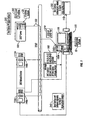
- FIG. 1 illustrates a block diagram of one embodiment of a computer system of the present invention for automatic configuration of new, replacement or unconfigured EAS network devices
- FIG. 2 illustrates a flow diagram of one embodiment of a method of the present invention for automatically configuring new, replacement or unconfigured EATS network devices
- FIG. 3 illustrates a flow diagram of a variation of one embodiment of the method of the present invention for automatically configuring new, replacement or unconfigured EAS network devices, the method including steps for entering a server address into the EAS network devices.
- FIG. 4 illustrates a block diagram of a machine having an architecture for implementing the present invention in software as an application program tangibly embodied on a program storage device.
- any reference in the specification to "one embodiment” or “an embodiment” means that a particular feature, structure, or characteristic described in connection with the embodiment is included in at least one embodiment.
- the appearances of the phrase “in one embodiment” in various places in the specification are not necessarily all referring to the same embodiment.
- Coupled and “connected” along with their derivatives. For example, some embodiments may be described using the term “connected” to indicate that two or more elements are in direct physical or electrical contact with each other. In another example, some embodiments may be described using the term “coupled” to indicate that two or more elements are in direct physical or electrical contact. The term “coupled,” however, may also mean that two or more elements are not in direct contact with each other, but yet still co-operate or interact with each other. The embodiments are not limited in this context.
- FIG. 1 illustrates a system 100 for automatic configuration of EAS network devices.
- An EAS network device may be an EAS detection system, EAS deactivator, EAS alarm response panel or any device having the ability to connect to a network for the purpose of generating, collecting or reporting EAS related data.
- the configuration process encompasses both storing of the configuration settings needed by the EAS network device to operate as well as configuring the device on the server software that is designed to manage the EAS network devices. Configuration also includes the automatic upgrading of EAS network device software or firmware upon device detection.
- the system 100 includes two parts: the server software 10 which resides on server 120; and the system architecture for implementing protocols. More particularly, the server software 10 is responsible for configuring and managing one or more EAS network devices, such as EAS network devices 110a and 110b.
- the term "configuration" is defined herein as including the storing of the settings configuration of the EAS network devices 110a and 110b as well as the automatic configuration of the EAS network devices 110a and 110b by the server software.
- the second part of system 100 is the system architecture which is designed to implement a protocol on at least one of the EAS network devices 110a and 110b and to allow the server 120 to query the device 110a, 110b to access information 160 about the device 110a, 110b for proper configuration purposes.
- the communication medium 130 for the system 100 may be, for example, a local area network (LAN) or wide area network (WAN) using typically transmission control protocol/ internet protocol (TC/IP) sockets 140a and 140b coupled to the EAS network devices 110a and 110b.
- LAN local area network
- WAN wide area network
- TC/IP transmission control protocol/ internet protocol
- the sockets 140a and 140b are coupled from server software or device manager software to the EAS devices by a virtual point-to-point connection for packet communication on one of the local area network (LAN) and a wide area network (WAN) between the server 120 and the EAS network devices 110a and 110b.
- the communication medium 130 is not limited to TCP/IP packet communication and other communication media may be used.
- the communication medium 130 may include an Ethernet interface to handle connections to external sources or over an interconnnected network of computer devices, commonly referred to as the ⁇ internet'.
- the communication medium is not limited to hard-wired connections but may also include wireless modes of communication.
- the software 10 resides on the server 120 and therefore resides on the same network 130 as the EAS network devices 110a, 110b.
- the server software 10 may have device specific and generic software modules to support the EAS network devices 110a, 110b.
- At least one TCP/IP socket 140a at EAS network device 110a or TCP/IP socket 140b at EAS network device 110b connects or couples at least one of the EAS network devices 110a or 110b to the network 130 for packet communication with the network 130.
- the server 120 "listen” or passively waits on a specified port 150a or 150b for connection requests from the EAS network devices 110a, 110b.
- the server 120 When a connection from an EAS network device 110a, 110b is detected, the server 120 accepts the connection and, using a specific protocol, queries the device 110a, 110b for information 160 such as, for example, pro-configured global device settings, the device type, MAC address, and firmware or software revision levels.
- the MAC address is used to uniquely define units, e.g., EAS network devices such as devices 110a, 110b, in the server 120. If the device being connected is an unconfigured device, the MAC address is currently not defined in the server, so the server 120 adds the device to its list of devices to manage, with the list appearing on server screen 170.
- the embodiments are not limited in this context
- the EAS network device 110a, 110b is then configured by the server 120 based upon the device type.
- the device configuration may include downloading pre-configured global device settings and downloading the appropriate revision of firmware or software required for proper device operation.
- the unconfigured EAS network device may be an entirely new device or a device replacing a prior defective device that already had been configured or a device reconnected to the network without proper configuration.
- the EAS network devices such as devices 110a and 110b, are manually-configurable to allow the installer to enter the MAC address of the defective device that is being replaced or the old MAC address.
- the server 120 Upon querying the EAS network device 110a, 110b, if the server receives an old, i.e., a previously valid, MAC address corresponding to a previously configured EAS network device, the server 120 configures the replacement device with the same configuration settings as the settings of the device being replaced.
- Each EAS network device 110a, 110b contains the necessary protocols to communicate the required information 160 to the server 120 so the network device such as 110a or 110b can be automatically configured.
- the required information 160 is the device type and the MAC address.
- the MAC address is used to uniquely define each EAS network device such as 110a, 110b in the server software 10.
- the device 110a, 110b first tries to connect to the server software 10 if the IP address of the server 120 is configured.
- the EAS network device 110a, 110b must have the server IP address to know where the server software 10 resides.
- the server IP address can be manually entered into the EAS network device or in one embodiment retrieved using a custom IP address option software package 20 residing on a dynamic host control protocol (DHCP) server 180.
- DHCP dynamic host control protocol
- the DHCP server 180 is connected or coupled to the communication medium 130 and supplies the IP address of the network server 120 to the EAS network devices such as 110a and 110b.
- the system 100 for automatically-configuring electronic article surveillance (EAS) devices coupled to a network includes: at least one electronic article surveillance (EAS) device 110a, 110b coupled to the network 130; a server 120 coupled to the network 130.
- the system 100 includes software 10 tangibly embodied as one or more application programs residing on the server 120 and its associated hardware.
- the server 120 is adapted to: (1) await or listen on a specified server port 150a, 150b for connection requests from the EAS network devices 110a, 110b; (2) accept the connection request from at least one of the EAS network devices 110a, 110b; (3) query the coupled EAS network device 110a, 110b for information 160 relating to the at least one coupled EAS network device 110a, 110b using a specific protocol for the server 120; and-(4)-configure the at least one coupled EAS network device 110a, 110b based upon the information 160 received from the at least one EAS network device 110a, 110b.
- the server 120 may also be configured for using the MAC address to uniquely define each EAS network device 110a, 110b.
- the server 120 configures the EAS network device 110a, 110b by sending appropriate settings, configuration and software revisions to the EAS network device. The embodiments are not limited in this context.
- the server 120 may be configured to "boot" at least one of the EAS network devices 110a, 110b before initiating the listening mode on a specified port such as 150a, 150b for connection requests from the EAS network devices 110a, 110b.
- the server 120 then instructs the system 100 to couple the at least one booted EAS network devices 110a, 110b to the network server 120 if the network server IP address is configured.
- a custom option software package 20 may also be included which is configured to retrieve the server internet protocol (IP) address from the dynamic host control protocol (DHCP) server 180 that supplies the IP address to the EAS network devices 110a, 110b.
- IP internet protocol
- DHCP dynamic host control protocol
- FIG. 2 illustrates a flow diagram of one embodiment of a method according to the present invention for automatically configuring new, replacement or unconfigured connected EAS network devices coupled to a network server.
- the EAS network devices such as devices 110a and 110b
- the server 120 performs the step of awaiting or listening on a specified port, such as 150a or 150b, for connection requests from the EAS network devices.
- the server 120 detects a connection from an EAS network device, such as 110a or 110b, the server proceeds by accepting the connection.
- the server 120 queries the connected EAS network device 110a or 110b for information 160 using a specific protocol for the server.
- the server 120 acts by configuring the EAS network device based upon the information received by sending configuration settings and software upgrades for any unconfigured network devices such as new, replacement or unconfigured connected devices.
- the server 120 adds the device to a list of devices for the server to manage.
- the information 160 may include: (a) pre-configured global device settings; (b) a connected or coupled EAS network device type; (c) a media access control (MAC) address; (d) a firmware revision level; and/or (e) a software revision level.
- the server performs the step 240 by using the MAC address to uniquely define each EAS network device 110a, 110b in the software 10 of the server 120.
- the server 120 performs the step 240 of configuring the EAS network device 110a, 110b by sending appropriate settings, and configuration and/or software revisions to the EAS network device 110a, 110b.
- the server 120 identifies the connected EAS network device 110a, 110b as a new EAS network device being added to the network.
- the server 120 may identify the coupled EAS network device 110a, 110b as an EAS network device 110a, 110b that replaces a previously configured EAS network device.
- the embodiments are not limited in this context.
- the step 240 of configuring the EAS network device Upon querying the connected EAS network device in step 230, if the server receives as the information an old, i.e., previously valid, media access control (MAC) address, the step 240 of configuring the EAS network device additionally or alternatively includes configuring the EAS network device with the configuration settings of the previously configured device that is being replaced.
- MAC media access control
- the step 210 of awaiting or listening on a specified port 150a, 150b for connection requests from the EAS network devices 110a, 110b additionally or alternatively includes using transmission control protocol/ internet protocol (TCP/IP) sockets 140a, 144b for packet communication on one of the local area network (LAN) and the wide area network (WAN) between the server 120 and the EAS network devices 110a, 110b.
- TCP/IP transmission control protocol/ internet protocol
- FIG. 3 illustrates a flow diagram of one particularly useful variation of the method of the present invention for automatically configuring new or replacement EAS network devices.
- the method includes the step 310 of booting the EAS network devices.
- step 320 it is determined whether the network server IP address is configured. If yes, in step 330, the at least one booted EAS network device is connected or coupled to the network server 120. If no, through OR gate 340, either step 350 or step 360 may be implemented.
- step 350 a user may manually enter the server IP address into the EAS network device 110a, 110b.
- an electromechanical interface such as, for example, a scanner, a key board, a data card, an optical reader, a cursor control device, e.g., a mouse or a terminal is configured to interface with the EAS network device 110a, 110b to allow the manual entry of the server IP address.
- the at least one booted EAS network device 110a, 110b may retrieve the server IP address from the dynamic host control protocol (DHCP) server 180 that supplies the IP address to the EAS network devices such as 110a, 110b.
- DHCP dynamic host control protocol
- the present invention may be implemented in various forms of hardware, software, firmware, special purpose processors, or a combination thereof.
- the present invention may be implemented in software as an application program tangibly embodied on a program storage device.
- the application program such as server software 10, 20 or any algorithm, flow diagram or block diagram disclosed herein, may be uploaded to, and executed by, a machine comprising any suitable architecture such as that shown in FIG. 4 .
- the machine 400 is implemented on a computer platform having hardware such as one or more central processing units (CPU) 402, a random access memory (RAM) 404, a read only memory (ROM) 406 and input/output (I/O) interface(s) such as keyboard 408, cursor control device (e.g., a mouse) 410 and display device 412.
- the computer platform also includes an operating system and micro instruction code.
- the various processes and functions described herein may either be part of the micro instruction code or part of the application program (or a combination thereof) which is executed via the operating system.
- various other peripheral devices may be connected to the computer platform such as an additional data storage device 414 and a printing device.
- an input device or mechanical interface e.g., a scanner device 416, may be coupled to the machine 400 for collecting image data.
- the invention provides a significant reduction in labor expenses for installation and maintenance of an EAS network device.
- the EAS network device can be installed (i.e., in this instance simply plugged in) by an untrained contractor. Since the configuration of the EAS network device is done automatically, the need for a trained service technician to install, replace or upgrade an EAS network device is negated in most instances.
Landscapes
- Physics & Mathematics (AREA)
- Engineering & Computer Science (AREA)
- Automation & Control Theory (AREA)
- Computer Security & Cryptography (AREA)
- Electromagnetism (AREA)
- General Physics & Mathematics (AREA)
- Information Transfer Between Computers (AREA)
- Stored Programmes (AREA)
- Small-Scale Networks (AREA)
- Data Exchanges In Wide-Area Networks (AREA)
- Computer And Data Communications (AREA)
Description
- The invention relates to a method and a system for automatic configuration of new, replacement and unconfigured connected electronic article surveillance (EAS) related network devices.
-
US 2004/0189471 A1 teaches a system and method for monitoring a facility. The system comprises monitoring tags wherein each monitoring tag emits an identifier signal unique to each monitoring tag, monitoring sensors wherein the monitoring sensors receive signals from the monitoring tags and relay the signals to one or more monitoring stations, wherein the monitoring stations log and display information associated with the signals received. The monitoring station alerts staff members of the events via a graphical user interface, pagers, email and alarms. In addition to the monitoring station server, monitoring station clients can also be incorporated to allow greater access to the user interface of the monitoring system. Personal computers already located around the facility can function as monitoring station clients. The personal computers and dedicated server would communicate over the current local area network of the facility. Even larger facilities can use multiple monitoring station servers, in which each monitoring station server would monitor different regions of the facility. -
US 2004/0095239 A1 teaches a computerized system providing a method to inventory articles, to locate lost or stolen articles and to recover a lost or stolen article, The system applies an electronic tag to each article of a multiplicity of articles or only to a valuable article and employs a computer to maintain an inventory of all articles. A global positioning system is used to locate a lost or stolen article as well as to track movements of the article. -
WO 2005/114603 A2, published on 1 december 2005 , teaches methods and devices for locating, identifying and provisioning devices in a network. For this a combination of EPIC code information and existing networking standards form the basis of identifying and provisioning methods. For example, location information included in a DHCPDISCOVER request can be used to determine appropriate configurations for networked devices. In some such implementations, the location information is read from an RFID tag near the networked device and is inserted in the DHCPDISCOVER request. - Typically, the local settings configuration for EAS devices is performed manually on-site, usually by trained service personnel. Although some EAS devices are contractor installable, the configuring of the operating parameters is typically performed by a trained service technician. For a major equipment roll out, sending a service technician to each site can be very expensive. In addition, if an EAS device needs to be replaced after initial installation, this follow-up installation is typically performed by a trained service technician. Also, if EAS network devices are subsequently added to the network, they would need to be manually configured on the server software.
- Since the configuration settings of the EAS network devices are stored either at the time of installation or after installation of the EAS network devices by a service person, a configurator program is typically developed specifically for the device. Software or firmware upgrades are usually done locally of on-site requiring a service person at each location to do the upgrade. Thus, it would be desirable to provide a system or method for automatically configuring EAS devices connected to a network.
- It is an object of the present invention to provide a method and system for the automatic configuration of EAS devices connected to a network.
- It is another object of the present invention provide a reduction in labor expenses for installation and maintenance of an EAS network device.
- It is yet another object of the present invention to enable an EAS network device to be installed by an untrained contractor.
- The present invention is directed to a system for the automatic-configuration of EAS devices connected to the network. The configuration process includes both the configuration stored on the EAS network device as well as device configuration stored on the server software designed to manage and administer the EAS network devices. The server software resides on a central server connected typically to a wide area network (WAN). The server software includes device manager software. Once an EAS network device is installed on the WAN, it goes through a discovery process that allows the server software to detect the device. When an unconfigured EAS network device is discovered by the server software, a determined protocol is used to ascertain specific information about the device, e.g., the type of device, media access control (MAC) address, current configuration information and the firmware or software revisions. The device is then automatically configured or registered in the server software as a device that needs to be managed.
- Based on the device type, the appropriate settings, configuration and software revisions are sent to the EAS network device. Once the EAS network device is properly configured, the server software monitors the device for events, alarms and data. If the EAS network device needs to be replaced, a replacement unit is automatically configured with the settings from the device being replaced.
- The present invention is directed also to a method of automatically configuring EAS devices coupled to a network server, and comprises the steps of: listening on a specified port for connection requests from at least one of the coupled EAS network devices; accepting the connection request from at least one of the coupled EAS network devices; querying the connected EAS network device for information relating to at least one coupled EAS network device; and configuring at least one coupled EAS network device based upon the information received from the at least one coupled EAS network device. In one particularly useful embodiment, the information relating to at least one coupled EAS network device is selected from the group consisting of (a) pre-configured global device settings, (b) the at least one coupled EAS network device type, (c) media access control (MAC) address, (d) firmware revision level, and (e) software revision level.
- When the information relating to the at least one coupled EAS network device is the MAC address, the method further comprises the step of using the MAC address to uniquely define each EAS network device in software of the server. Alternatively, when the information relating to the at least one coupled EAS network device is the at least one coupled EAS network device type, the step of configuring the EAS network device includes sending configuration settings and software revisions to the at least one coupled EAS network device appropriate for the type of EAS network device.
- After the step of querying the at least one coupled EAS network device for information relating to the at least one coupled EAS network device, the method may further comprise the steps of: analyzing the information received from the at least one coupled EAS network device and determining if the at least one EAS network device is defined in the server. In addition, if the at least one EAS network device is not defined in the server, the method includes adding the at least one EAS network device to a list of devices for the server to manage.
- After the step of querying the at least one coupled EAS network device for information relating to the at least one coupled EAS network device, the method may further comprise the step of: analyzing the information received from the at least one -coupled EAS network device and determining if the at least one EAS network device is defined in the server. If the at least one coupled EAS network device is not defined in the server, the method may further include identifying the at least one coupled EAS network device as a new EAS network device being added to the network..
- Alternatively, the method may further include identifying the at least one coupled EAS network device as an EAS network device that replaces a previously -configured EAS network device. Upon querying the at least one coupled EAS network device, if the server receives as the information relating to the at least one coupled EAS network device a previously valid media access control (MAC) address or any similar identifiable address corresponding to the previously configured EAS network device, the step of configuring the EAS network device may include configuring the at least one coupled EAS network device with configuration settings of the previously configured EAS network device being replaced.
- The step of listening on a specified port for connection requests from the at least one coupled EAS network device may include using transmission control protocol/ internet protocol (TCP/IP) sockets for packet communication on one of a local area network (LAN) and a wide area network (WAN) between the server and the EAS network devices. In a particularly useful embodiment, before the step of listening on a specified port for connection requests from the at least one coupled EAS network device, the method may further comprise the steps of: booting at least one of the EAS network devices; and coupling or connecting the at least one booted EAS network devices to the network server if the network server IP address is configured. In addition, the method may further comprise the step of: manually entering the server IP address into the EAS network device if the network server internet protocol (IP) address is not configured. Alternatively, if the network server internet protocol (IP) address is not configured, the method may further comprise the step of: retrieving the server IP address from a dynamic host control protocol (DHCP) server that supplies the IP address to the EAS network devices.
- In one particularly useful embodiment, the foregoing method steps are implemented by a program storage device readable by machine, tangibly embodying a program of instructions executable by the machine to perform method steps for automatically configuring electronic article surveillance (EAS) devices coupled to a network server.
- The subject matter regarded as the embodiments is particularly pointed out and distinctly claimed in the concluding portion of the specification. The embodiments, however, both as to organization and method of operation, together with objects, features, and advantages thereof, may best be understood by reference to the following detailed description when read with the accompanying drawings in which:
-
FIG. 1 illustrates a block diagram of one embodiment of a computer system of the present invention for automatic configuration of new, replacement or unconfigured EAS network devices; -
FIG. 2 illustrates a flow diagram of one embodiment of a method of the present invention for automatically configuring new, replacement or unconfigured EATS network devices; and -
FIG. 3 illustrates a flow diagram of a variation of one embodiment of the method of the present invention for automatically configuring new, replacement or unconfigured EAS network devices, the method including steps for entering a server address into the EAS network devices. -
FIG. 4 illustrates a block diagram of a machine having an architecture for implementing the present invention in software as an application program tangibly embodied on a program storage device. - Numerous specific details may be set forth herein to provide a thorough understanding of the embodiments of the invention. It will be understood by those skilled in the art, however, that the embodiments of the invention may be practiced without these specific details. In other instances, well-known methods, procedures, components and circuits have not been described in detail so as not to obscure the embodiments of the invention. It can be appreciated that the specific structural and functional details disclosed herein may be representative and do not necessarily limit the scope of the invention.
- It is worthy to note that any reference in the specification to "one embodiment" or "an embodiment" means that a particular feature, structure, or characteristic described in connection with the embodiment is included in at least one embodiment. The appearances of the phrase "in one embodiment" in various places in the specification are not necessarily all referring to the same embodiment.
- Some embodiments may be described using the expression "coupled" and "connected" along with their derivatives. For example, some embodiments may be described using the term "connected" to indicate that two or more elements are in direct physical or electrical contact with each other. In another example, some embodiments may be described using the term "coupled" to indicate that two or more elements are in direct physical or electrical contact. The term "coupled," however, may also mean that two or more elements are not in direct contact with each other, but yet still co-operate or interact with each other. The embodiments are not limited in this context.
- Referring now in detail to the drawings wherein like parts may be designated by like reference numerals throughout,
FIG. 1 illustrates a system 100 for automatic configuration of EAS network devices. An EAS network device may be an EAS detection system, EAS deactivator, EAS alarm response panel or any device having the ability to connect to a network for the purpose of generating, collecting or reporting EAS related data. The configuration process encompasses both storing of the configuration settings needed by the EAS network device to operate as well as configuring the device on the server software that is designed to manage the EAS network devices. Configuration also includes the automatic upgrading of EAS network device software or firmware upon device detection. - The system 100 includes two parts: the server software 10 which resides on
server 120; and the system architecture for implementing protocols. More particularly, the server software 10 is responsible for configuring and managing one or more EAS network devices, such asEAS network devices EAS network devices EAS network devices - As noted above, the second part of system 100 is the system architecture which is designed to implement a protocol on at least one of the
EAS network devices server 120 to query thedevice information 160 about thedevice communication medium 130 for the system 100 may be, for example, a local area network (LAN) or wide area network (WAN) using typically transmission control protocol/ internet protocol (TC/IP)sockets EAS network devices sockets server 120 and theEAS network devices communication medium 130 is not limited to TCP/IP packet communication and other communication media may be used. Thecommunication medium 130 may include an Ethernet interface to handle connections to external sources or over an interconnnected network of computer devices, commonly referred to as the `internet'. The communication medium is not limited to hard-wired connections but may also include wireless modes of communication. - The software 10 resides on the
server 120 and therefore resides on thesame network 130 as theEAS network devices EAS network devices IP socket 140a atEAS network device 110a or TCP/IP socket 140b atEAS network device 110b connects or couples at least one of theEAS network devices network 130 for packet communication with thenetwork 130. Using the TCP/IP sockets EAS network devices server 120 "listen" or passively waits on a specifiedport EAS network devices EAS network device server 120 accepts the connection and, using a specific protocol, queries thedevice information 160 such as, for example, pro-configured global device settings, the device type, MAC address, and firmware or software revision levels. The MAC address is used to uniquely define units, e.g., EAS network devices such asdevices server 120. If the device being connected is an unconfigured device, the MAC address is currently not defined in the server, so theserver 120 adds the device to its list of devices to manage, with the list appearing onserver screen 170. The embodiments are not limited in this context - The
EAS network device server 120 based upon the device type. The device configuration may include downloading pre-configured global device settings and downloading the appropriate revision of firmware or software required for proper device operation. - When the
server 120 detects an unconfigured EAS network device, such asEAS network devices devices EAS network device server 120 configures the replacement device with the same configuration settings as the settings of the device being replaced. - Each
EAS network device information 160 to theserver 120 so the network device such as 110a or 110b can be automatically configured. The requiredinformation 160 is the device type and the MAC address. The MAC address is used to uniquely define each EAS network device such as 110a, 110b in the server software 10. When an EAS network device such as 110a or 110b is booted, thedevice server 120 is configured. TheEAS network device option software package 20 residing on a dynamic host control protocol (DHCP)server 180. TheDHCP server 180 is connected or coupled to thecommunication medium 130 and supplies the IP address of thenetwork server 120 to the EAS network devices such as 110a and 110b. - In one particularly useful embodiment, the system 100 for automatically-configuring electronic article surveillance (EAS) devices coupled to a network includes: at least one electronic article surveillance (EAS)
device network 130; aserver 120 coupled to thenetwork 130. The system 100 includes software 10 tangibly embodied as one or more application programs residing on theserver 120 and its associated hardware. Theserver 120 is adapted to: (1) await or listen on a specifiedserver port EAS network devices EAS network devices EAS network device information 160 relating to the at least one coupledEAS network device server 120; and-(4)-configure the at least one coupledEAS network device information 160 received from the at least oneEAS network device server 120 may also be configured for using the MAC address to uniquely define eachEAS network device information 160 is the coupled EAS network device type, theserver 120 configures theEAS network device - Similarly, in another particularly useful embodiment, the
server 120 may be configured to "boot" at least one of theEAS network devices EAS network devices server 120 then instructs the system 100 to couple the at least one bootedEAS network devices network server 120 if the network server IP address is configured. A customoption software package 20 may also be included which is configured to retrieve the server internet protocol (IP) address from the dynamic host control protocol (DHCP)server 180 that supplies the IP address to theEAS network devices -
FIG. 2 illustrates a flow diagram of one embodiment of a method according to the present invention for automatically configuring new, replacement or unconfigured connected EAS network devices coupled to a network server. First, instep 200, the EAS network devices, such asdevices step 210, theserver 120 performs the step of awaiting or listening on a specified port, such as 150a or 150b, for connection requests from the EAS network devices. Instep 220, when theserver 120 detects a connection from an EAS network device, such as 110a or 110b, the server proceeds by accepting the connection. Instep 230, theserver 120 queries the connectedEAS network device information 160 using a specific protocol for the server. Instep 240, theserver 120 acts by configuring the EAS network device based upon the information received by sending configuration settings and software upgrades for any unconfigured network devices such as new, replacement or unconfigured connected devices. Instep 250, when theinformation 160 received from the connected EAS network device such as 110a or 110b is not defined in theserver 120, theserver 120 adds the device to a list of devices for the server to manage. - As noted previously, the
information 160 may include: (a) pre-configured global device settings; (b) a connected or coupled EAS network device type; (c) a media access control (MAC) address; (d) a firmware revision level; and/or (e) a software revision level. When theinformation 160 is the MAC address, the server performs thestep 240 by using the MAC address to uniquely define eachEAS network device server 120. When theinformation 160 is a connected or coupled EAS network device type, theserver 120 performs thestep 240 of configuring theEAS network device EAS network device EAS network device server 120, theserver 120 identifies the connectedEAS network device EAS network device server 120, theserver 120 may identify the coupledEAS network device EAS network device - Upon querying the connected EAS network device in
step 230, if the server receives as the information an old, i.e., previously valid, media access control (MAC) address, thestep 240 of configuring the EAS network device additionally or alternatively includes configuring the EAS network device with the configuration settings of the previously configured device that is being replaced. - The
step 210 of awaiting or listening on a specifiedport EAS network devices sockets 140a, 144b for packet communication on one of the local area network (LAN) and the wide area network (WAN) between theserver 120 and theEAS network devices -
FIG. 3 illustrates a flow diagram of one particularly useful variation of the method of the present invention for automatically configuring new or replacement EAS network devices. First, prior to performing thestep 210 of awaiting or listening on a specified port such as 140a, 140b for connection requests from theEAS network devices step 310 of booting the EAS network devices. Instep 320, it is determined whether the network server IP address is configured. If yes, instep 330, the at least one booted EAS network device is connected or coupled to thenetwork server 120. If no, through ORgate 340, either step 350 or step 360 may be implemented. Instep 350, a user may manually enter the server IP address into theEAS network device EAS network device step 360, the at least one bootedEAS network device server 180 that supplies the IP address to the EAS network devices such as 110a, 110b. The embodiments are not limited in this context. - It is to be understood that the present invention may be implemented in various forms of hardware, software, firmware, special purpose processors, or a combination thereof. In one embodiment, the present invention may be implemented in software as an application program tangibly embodied on a program storage device. The application program, such as
server software 10, 20 or any algorithm, flow diagram or block diagram disclosed herein, may be uploaded to, and executed by, a machine comprising any suitable architecture such as that shown inFIG. 4 . Preferably, themachine 400 is implemented on a computer platform having hardware such as one or more central processing units (CPU) 402, a random access memory (RAM) 404, a read only memory (ROM) 406 and input/output (I/O) interface(s) such askeyboard 408, cursor control device (e.g., a mouse) 410 anddisplay device 412. The computer platform also includes an operating system and micro instruction code. The various processes and functions described herein may either be part of the micro instruction code or part of the application program (or a combination thereof) which is executed via the operating system. In addition, various other peripheral devices may be connected to the computer platform such as an additionaldata storage device 414 and a printing device. Furthermore, an input device or mechanical interface, e.g., ascanner device 416, may be coupled to themachine 400 for collecting image data. - It is to be further understood that, because some of the constituent system components and method steps depicted in the accompanying figures may be implemented in software, the actual connections between the system components (or the process steps) may differ depending upon the manner in which the present invention is programmed. Given the teachings of the present invention provided herein, one of ordinary skill in the related art will be able to contemplate these and similar implementations or configurations of the present invention.
- Therefore and as can be appreciated, the invention provides a significant reduction in labor expenses for installation and maintenance of an EAS network device. Moreover, the EAS network device can be installed (i.e., in this instance simply plugged in) by an untrained contractor. Since the configuration of the EAS network device is done automatically, the need for a trained service technician to install, replace or upgrade an EAS network device is negated in most instances.
- While certain features of the embodiments of the invention have been illustrated as describe herein, many modifications, substitutions, changes and equivalents will now occur to those skilled in the art. It is, therefore, to be understood that the appended claims are intended to cover all such modifications and changes as fall within the scope of the embodiments of the invention.
Claims (17)
- A system (100) for automatically configuring electronic article surveillance (EAS) devices (110a, 110b) in the form of an EAS detection system, EAS deactivator, EAS alarm response panel and/or any device having the ability to connect to a network (130) for the purpose of generating, collecting or reporting EAS related data, coupled to a network (130), comprising:a server (120) coupled to the network, the server (120) adapted to(1) listen on a specified port (150a, 150b) for connection requests from at least one coupled EAS network device (110a, 110b);(2) accept the connection request from at least one coupled EAS network device (110a, 110b);(3) query at least one coupled EAS network device (110a, 110b) for information relating to at least one EAS network device (110a, 110b); and(4) configure at least one coupled EAS network device (110a, 110b) based upon the information received from at least one EAS network device (110a, 110b),
characterized in thatthe server (120) is configured to boot at least one of the at least one coupled EAS network devices (110a, 110b) before listening on a specified port (150a, 150b) for connection requests from the at least one coupled EAS network devices (110a, 110b) the system further comprising at least one electromechanical interface (408) interfacing with the at least one booted EAS network device (110a, 110b) and configured to retrieve the server internet protocol (IP) address from a dynamic host control protocol (DHCP) server (180) that supplies the IP address to the EAS network devices (110a, 110b). - The system according to claim 1, wherein the server (120) includes software which(1) listens on a specified port (150a, 150b) for connection requests from at least one coupled EAS network device (110a, 110b);(2) accepts the connection request from the at least one coupled EAS network device (110a, 110b);(3) queries the at least one coupled EAS network device (110a, 110b) for information relating to the at least one EAS network device (110a, 110b); and(4) configures the at least one coupled EAS network device (110a, 110b) based upon the information received from the at least one EAS network device (110a, 110b).
- The system according to claim 1, wherein the server (120) includes hardware which(1) listens on a specified port (150a, 150b) for connection requests from at least one coupled EAS network device (110a, 110b);(2) accepts the connection request from the at least one coupled EAS network device (110a, 110b);(3) queries the at least one coupled EAS network device (110a, 110b) for information relating to the at least one EAS network device (110a, 110b); and(4) configures the at least one coupled EAS network device (110a, 110b) based upon the information received from the at least one EAS network device (110a, 110b),
- The system according to claim 1, wherein:the information relating to the at least one coupled EAS network device (110a, 110b) is selected from the group consisting of (a) pre-configured global device settings, (b) the at least one coupled EAS network device type, (c) media access control (MAC) address, (d) firmware revision level, and (e) software revision level.
- The system according to claim 4, wherein the information relating to the at least one coupled EAS network device (110a, 110b) is the MAC address, and the server (120) is configured to use the MAC address to uniquely define each EAS network device (110a, 110b) in software of the server (120).
- The system according to claim 4, wherein the information relating to the at least one coupled EAS network device (110a, 110b) is the at least one coupled EAS network device type, and the server (120) configures the at least one coupled EAS network device (110a, 110b) by sending configuration settings and software revisions to the at least one coupled EAS network device (110a, 110b) appropriate for the type of the at least one coupled EAS network device (110a, 110b).
- The system according to claim 1, wherein the server (120) adds the at least one coupled EAS device (110a, 110b) to a list of devices for the server (120) to manage when the information received from the at least one coupled EAS network device (110a, 110b) is not defined in the server (120).
- The system according to claim 1, wherein the server identifies the at least one coupled EAS network device (110a, 110b) as a new EAS network device (110a, 110b) being added to the network (130) when the information received from the at least one coupled EAS network device (110a, 110b) is not defined in the server (120).
- The system according to claim 1, wherein the server (120) identifies the at least one coupled EAS network device (110a, 110b) as an EAS network device (110a, 110b) that replaces a previously configured EAS network device (110a, 110b) when the information received from the at least one coupled EAS network device (110a, 110b) is not defined in the server (120).
- The system according to claim 9, wherein upon querying the connected EAS network device (110a, 110b), the server configures the at least one coupled EAS network device (110a, 110b) with configuration settings of the previously configured EAS network device (110a, 110b) if the server (120) receives as the information a previously valid media access control (MAC) address corresponding to the previously configured EAS network device (110a110b).
- The system according to claim 1, further comprising:at least one transmission control protocol/ internet protocol (TCP/IP) socket (140a, 140b) coupling the at least one coupled EAS network device (110a, 110b) to the network (130) for packet communication with the network (130).
- The system according to claim 11, wherein the server (120) listens through the at least one TCP/IP socket (140a, 140b) on a specified port (150a, 150b) for connection requests from the at least one coupled EAS network device (110a, 110b).
- The system according to claim 1, wherein the network (130) is one of a local area network (LAN) and a wide area network (WAN).
- The system according to claim 1, wherein the server (120) is configured to connect the at least one booted EAS network devices (110a, 110b) to the network server (120) if the network server IP address is configured.
- The system according to claim 1, further comprising at least one electromechanical interface (408) interfacing with the at least one booted EAS network device (110a, 110b) and configured to allow a user to manual enter the server internet protocol (IP) address into the at least one booted EAS network device (110a, 110b).
- The system according to claim 15, wherein the at least one electromechanical interface is selected from the group consisting of (a) a key board; (b) a data card; (c) an optical reader; (d) a cursor control device and (e) a terminal.
- The system according to claim 2, wherein the software has device specific and generic software modules to support the EAS network devices (110a, 110b).
Applications Claiming Priority (2)
| Application Number | Priority Date | Filing Date | Title |
|---|---|---|---|
| US62831304P | 2004-11-16 | 2004-11-16 | |
| PCT/US2005/041366 WO2006055563A1 (en) | 2004-11-16 | 2005-11-16 | Automatic configuration of new or replacement eas network devices |
Publications (2)
| Publication Number | Publication Date |
|---|---|
| EP1812912A1 EP1812912A1 (en) | 2007-08-01 |
| EP1812912B1 true EP1812912B1 (en) | 2013-01-02 |
Family
ID=36087628
Family Applications (1)
| Application Number | Title | Priority Date | Filing Date |
|---|---|---|---|
| EP05845514A Expired - Lifetime EP1812912B1 (en) | 2004-11-16 | 2005-11-16 | Automatic configuration of new or replacement eas network devices |
Country Status (8)
| Country | Link |
|---|---|
| US (1) | US20080297347A1 (en) |
| EP (1) | EP1812912B1 (en) |
| JP (1) | JP2008521349A (en) |
| CN (1) | CN100595803C (en) |
| AU (1) | AU2005307851B2 (en) |
| CA (1) | CA2587562C (en) |
| ES (1) | ES2398697T3 (en) |
| WO (1) | WO2006055563A1 (en) |
Families Citing this family (6)
| Publication number | Priority date | Publication date | Assignee | Title |
|---|---|---|---|---|
| NL2007029C2 (en) * | 2011-02-24 | 2012-08-27 | Cross Point B V | SYSTEM WITH ARTICLE-MONITORING DEVICE, ARTICLE-MONITORING DEVICE AND METHOD FOR VISUALIZING SET-UP INFORMATION. |
| US20150160935A1 (en) * | 2013-12-06 | 2015-06-11 | Vivint, Inc. | Managing device configuration information |
| US11120274B2 (en) | 2014-04-10 | 2021-09-14 | Sensormatic Electronics, LLC | Systems and methods for automated analytics for security surveillance in operation areas |
| US10057546B2 (en) * | 2014-04-10 | 2018-08-21 | Sensormatic Electronics, LLC | Systems and methods for automated cloud-based analytics for security and/or surveillance |
| US11093545B2 (en) | 2014-04-10 | 2021-08-17 | Sensormatic Electronics, LLC | Systems and methods for an automated cloud-based video surveillance system |
| CN107943438A (en) * | 2017-12-21 | 2018-04-20 | 国网河北省电力有限公司衡水供电分公司 | The office optimization method of unattended operation transformer station |
Family Cites Families (13)
| Publication number | Priority date | Publication date | Assignee | Title |
|---|---|---|---|---|
| US6098116A (en) * | 1996-04-12 | 2000-08-01 | Fisher-Rosemont Systems, Inc. | Process control system including a method and apparatus for automatically sensing the connection of devices to a network |
| US6031978A (en) * | 1996-06-28 | 2000-02-29 | International Business Machines Corporation | System, method and program for enabling a client to reconnect to a same server in a network of computer systems after the server has moved to a different network address |
| US5918016A (en) * | 1997-06-10 | 1999-06-29 | Texas Instruments Incorporated | System with program for automating protocol assignments when newly connected to varing computer network configurations |
| US6209089B1 (en) * | 1998-08-12 | 2001-03-27 | Microsoft Corporation | Correcting for changed client machine hardware using a server-based operating system |
| US6169483B1 (en) * | 1999-05-04 | 2001-01-02 | Sensormatic Electronics Corporation | Self-checkout/self-check-in RFID and electronics article surveillance system |
| US6766334B1 (en) * | 2000-11-21 | 2004-07-20 | Microsoft Corporation | Project-based configuration management method and apparatus |
| JP2003032277A (en) * | 2001-07-12 | 2003-01-31 | Allied Tereshisu Kk | Management method and system of network equipment |
| CN100511300C (en) * | 2002-04-11 | 2009-07-08 | 传感电子公司 | System and method for optimizing range of an electronic article surveillance system |
| US7075412B1 (en) * | 2002-05-30 | 2006-07-11 | Thingmagic L.L.C. | Methods and apparatus for operating a radio device |
| JP2004078392A (en) * | 2002-08-13 | 2004-03-11 | Seiko Epson Corp | Automatic configuration of network devices |
| US7138916B2 (en) * | 2002-10-29 | 2006-11-21 | Jeffrey Schwartz | Computerized risk management program |
| US7167094B2 (en) * | 2003-01-31 | 2007-01-23 | Secure Care Products, Inc. | Systems and methods for providing secure environments |
| JP2004320410A (en) * | 2003-04-16 | 2004-11-11 | Matsushita Electric Ind Co Ltd | Wireless device, wireless terminal device, and wireless system |
-
2005
- 2005-11-16 JP JP2007543175A patent/JP2008521349A/en active Pending
- 2005-11-16 AU AU2005307851A patent/AU2005307851B2/en not_active Expired
- 2005-11-16 US US11/667,990 patent/US20080297347A1/en not_active Abandoned
- 2005-11-16 ES ES05845514T patent/ES2398697T3/en not_active Expired - Lifetime
- 2005-11-16 WO PCT/US2005/041366 patent/WO2006055563A1/en not_active Ceased
- 2005-11-16 CN CN200580045133A patent/CN100595803C/en not_active Expired - Lifetime
- 2005-11-16 EP EP05845514A patent/EP1812912B1/en not_active Expired - Lifetime
- 2005-11-16 CA CA2587562A patent/CA2587562C/en not_active Expired - Lifetime
Also Published As
| Publication number | Publication date |
|---|---|
| ES2398697T3 (en) | 2013-03-21 |
| AU2005307851B2 (en) | 2009-09-24 |
| JP2008521349A (en) | 2008-06-19 |
| CA2587562C (en) | 2016-01-12 |
| AU2005307851A1 (en) | 2006-05-26 |
| EP1812912A1 (en) | 2007-08-01 |
| CA2587562A1 (en) | 2006-05-26 |
| CN101091196A (en) | 2007-12-19 |
| HK1111505A1 (en) | 2008-08-08 |
| CN100595803C (en) | 2010-03-24 |
| WO2006055563A1 (en) | 2006-05-26 |
| US20080297347A1 (en) | 2008-12-04 |
Similar Documents
| Publication | Publication Date | Title |
|---|---|---|
| US7013462B2 (en) | Method to map an inventory management system to a configuration management system | |
| US7436303B2 (en) | Rack sensor controller for asset tracking | |
| CN100586073C (en) | Simple and dynamic configuration of network equipment | |
| KR100477578B1 (en) | system and method for remote management of information device in home network | |
| US20070055756A1 (en) | Dynamically extensible and automatically configurable building automation system and architecture | |
| US20070118654A1 (en) | Method and apparatus for provisioning heterogeneous operating systems onto heterogeneous hardware systems | |
| US20080069121A1 (en) | Gateway For A Local Network System | |
| JP2004013901A (en) | Method and system for monitoring devices connected to a network and displaying device status | |
| US7844766B1 (en) | System and method for location specific computer enabled services/monitoring | |
| US20100306347A1 (en) | Systems and methods for detecting, monitoring, and configuring services in a network | |
| EP2863281B1 (en) | System and method to configure a field device | |
| EP2832039B1 (en) | Platform independent management controller | |
| US20040049575A1 (en) | Electronic device monitoring method, electronic device, computer, and program thereof | |
| AU2005307851B2 (en) | Automatic configuration of new or replacement EAS network devices | |
| US7519069B2 (en) | Internet protocol address updating system and related method | |
| EP1096444A2 (en) | Method and system for configuration of self-service financial transaction terminals for a common software release | |
| EP2040418B1 (en) | Program control method for network devices and network system | |
| US8677323B2 (en) | Recording medium storing monitoring program, monitoring method, and monitoring system | |
| JP2007183837A (en) | ENVIRONMENT SETTING PROGRAM, ENVIRONMENT SETTING SYSTEM, AND ENVIRONMENT SETTING METHOD | |
| WO2014145597A2 (en) | Systems and methods for identifying electronic equipment among a plurality of electronic equipment in an environment | |
| HK1111505B (en) | Automatic configuration of new or replacement eas network devices | |
| KR20230161170A (en) | Mehtod, apparatus, and program for managing kiosk system for unmanned store management | |
| EP1484676B1 (en) | Configuring a computer in a network | |
| JP2003140999A (en) | Electronic device monitoring method and system, electronic device and computer | |
| JPH11296467A (en) | Network device control method and apparatus, recording medium |
Legal Events
| Date | Code | Title | Description |
|---|---|---|---|
| PUAI | Public reference made under article 153(3) epc to a published international application that has entered the european phase |
Free format text: ORIGINAL CODE: 0009012 |
|
| 17P | Request for examination filed |
Effective date: 20070612 |
|
| AK | Designated contracting states |
Kind code of ref document: A1 Designated state(s): AT BE BG CH CY CZ DE DK EE ES FI FR GB GR HU IE IS IT LI LT LU LV MC NL PL PT RO SE SI SK TR |
|
| DAX | Request for extension of the european patent (deleted) | ||
| 17Q | First examination report despatched |
Effective date: 20090129 |
|
| RAP1 | Party data changed (applicant data changed or rights of an application transferred) |
Owner name: SENSORMATIC ELECTRONICS, LLC |
|
| GRAP | Despatch of communication of intention to grant a patent |
Free format text: ORIGINAL CODE: EPIDOSNIGR1 |
|
| GRAS | Grant fee paid |
Free format text: ORIGINAL CODE: EPIDOSNIGR3 |
|
| GRAA | (expected) grant |
Free format text: ORIGINAL CODE: 0009210 |
|
| AK | Designated contracting states |
Kind code of ref document: B1 Designated state(s): AT BE BG CH CY CZ DE DK EE ES FI FR GB GR HU IE IS IT LI LT LU LV MC NL PL PT RO SE SI SK TR |
|
| REG | Reference to a national code |
Ref country code: GB Ref legal event code: FG4D |
|
| REG | Reference to a national code |
Ref country code: CH Ref legal event code: EP Ref country code: AT Ref legal event code: REF Ref document number: 591979 Country of ref document: AT Kind code of ref document: T Effective date: 20130115 |
|
| REG | Reference to a national code |
Ref country code: IE Ref legal event code: FG4D |
|
| REG | Reference to a national code |
Ref country code: DE Ref legal event code: R096 Ref document number: 602005037761 Country of ref document: DE Effective date: 20130228 |
|
| REG | Reference to a national code |
Ref country code: ES Ref legal event code: FG2A Ref document number: 2398697 Country of ref document: ES Kind code of ref document: T3 Effective date: 20130321 |
|
| REG | Reference to a national code |
Ref country code: AT Ref legal event code: MK05 Ref document number: 591979 Country of ref document: AT Kind code of ref document: T Effective date: 20130102 |
|
| REG | Reference to a national code |
Ref country code: NL Ref legal event code: VDEP Effective date: 20130102 |
|
| PG25 | Lapsed in a contracting state [announced via postgrant information from national office to epo] |
Ref country code: SI Free format text: LAPSE BECAUSE OF FAILURE TO SUBMIT A TRANSLATION OF THE DESCRIPTION OR TO PAY THE FEE WITHIN THE PRESCRIBED TIME-LIMIT Effective date: 20130102 |
|
| REG | Reference to a national code |
Ref country code: DE Ref legal event code: R082 Ref document number: 602005037761 Country of ref document: DE Representative=s name: HAFNER & PARTNER, DE |
|
| REG | Reference to a national code |
Ref country code: LT Ref legal event code: MG4D |
|
| PG25 | Lapsed in a contracting state [announced via postgrant information from national office to epo] |
Ref country code: AT Free format text: LAPSE BECAUSE OF FAILURE TO SUBMIT A TRANSLATION OF THE DESCRIPTION OR TO PAY THE FEE WITHIN THE PRESCRIBED TIME-LIMIT Effective date: 20130102 Ref country code: SE Free format text: LAPSE BECAUSE OF FAILURE TO SUBMIT A TRANSLATION OF THE DESCRIPTION OR TO PAY THE FEE WITHIN THE PRESCRIBED TIME-LIMIT Effective date: 20130102 Ref country code: BG Free format text: LAPSE BECAUSE OF FAILURE TO SUBMIT A TRANSLATION OF THE DESCRIPTION OR TO PAY THE FEE WITHIN THE PRESCRIBED TIME-LIMIT Effective date: 20130402 Ref country code: CY Free format text: LAPSE BECAUSE OF FAILURE TO SUBMIT A TRANSLATION OF THE DESCRIPTION OR TO PAY THE FEE WITHIN THE PRESCRIBED TIME-LIMIT Effective date: 20130102 Ref country code: LT Free format text: LAPSE BECAUSE OF FAILURE TO SUBMIT A TRANSLATION OF THE DESCRIPTION OR TO PAY THE FEE WITHIN THE PRESCRIBED TIME-LIMIT Effective date: 20130102 Ref country code: IS Free format text: LAPSE BECAUSE OF FAILURE TO SUBMIT A TRANSLATION OF THE DESCRIPTION OR TO PAY THE FEE WITHIN THE PRESCRIBED TIME-LIMIT Effective date: 20130502 Ref country code: CZ Free format text: LAPSE BECAUSE OF FAILURE TO SUBMIT A TRANSLATION OF THE DESCRIPTION OR TO PAY THE FEE WITHIN THE PRESCRIBED TIME-LIMIT Effective date: 20130102 Ref country code: BE Free format text: LAPSE BECAUSE OF FAILURE TO SUBMIT A TRANSLATION OF THE DESCRIPTION OR TO PAY THE FEE WITHIN THE PRESCRIBED TIME-LIMIT Effective date: 20130102 |
|
| REG | Reference to a national code |
Ref country code: DE Ref legal event code: R081 Ref document number: 602005037761 Country of ref document: DE Owner name: TYCO FIRE & SECURITY GMBH, CH Free format text: FORMER OWNER: SENSORMATIC ELECTRONICS CORP., BOCA RATON, US Effective date: 20130103 Ref country code: DE Ref legal event code: R081 Ref document number: 602005037761 Country of ref document: DE Owner name: TYCO FIRE & SECURITY GMBH, CH Free format text: FORMER OWNER: SENSORMATIC ELECTRONICS, LLC, BOCA RATON, US Effective date: 20130612 Ref country code: DE Ref legal event code: R082 Ref document number: 602005037761 Country of ref document: DE Representative=s name: HAFNER & PARTNER, DE Effective date: 20130612 Ref country code: DE Ref legal event code: R081 Ref document number: 602005037761 Country of ref document: DE Owner name: TYCO FIRE & SECURITY GMBH, CH Free format text: FORMER OWNER: SENSORMATIC ELECTRONICS, LLC, BOCA RATON, FLA., US Effective date: 20130612 Ref country code: DE Ref legal event code: R081 Ref document number: 602005037761 Country of ref document: DE Owner name: TYCO FIRE & SECURITY GMBH, CH Free format text: FORMER OWNER: SENSORMATIC ELECTRONICS CORP., BOCA RATON, FLA., US Effective date: 20130103 Ref country code: DE Ref legal event code: R082 Ref document number: 602005037761 Country of ref document: DE Representative=s name: HAFNER & KOHL, DE Effective date: 20130612 Ref country code: DE Ref legal event code: R082 Ref document number: 602005037761 Country of ref document: DE Representative=s name: HAFNER & KOHL PATENTANWALTSKANZLEI RECHTSANWAL, DE Effective date: 20130612 |
|
| PG25 | Lapsed in a contracting state [announced via postgrant information from national office to epo] |
Ref country code: NL Free format text: LAPSE BECAUSE OF FAILURE TO SUBMIT A TRANSLATION OF THE DESCRIPTION OR TO PAY THE FEE WITHIN THE PRESCRIBED TIME-LIMIT Effective date: 20130102 Ref country code: FI Free format text: LAPSE BECAUSE OF FAILURE TO SUBMIT A TRANSLATION OF THE DESCRIPTION OR TO PAY THE FEE WITHIN THE PRESCRIBED TIME-LIMIT Effective date: 20130102 Ref country code: GR Free format text: LAPSE BECAUSE OF FAILURE TO SUBMIT A TRANSLATION OF THE DESCRIPTION OR TO PAY THE FEE WITHIN THE PRESCRIBED TIME-LIMIT Effective date: 20130403 Ref country code: PT Free format text: LAPSE BECAUSE OF FAILURE TO SUBMIT A TRANSLATION OF THE DESCRIPTION OR TO PAY THE FEE WITHIN THE PRESCRIBED TIME-LIMIT Effective date: 20130502 Ref country code: LV Free format text: LAPSE BECAUSE OF FAILURE TO SUBMIT A TRANSLATION OF THE DESCRIPTION OR TO PAY THE FEE WITHIN THE PRESCRIBED TIME-LIMIT Effective date: 20130102 Ref country code: PL Free format text: LAPSE BECAUSE OF FAILURE TO SUBMIT A TRANSLATION OF THE DESCRIPTION OR TO PAY THE FEE WITHIN THE PRESCRIBED TIME-LIMIT Effective date: 20130102 |
|
| PG25 | Lapsed in a contracting state [announced via postgrant information from national office to epo] |
Ref country code: RO Free format text: LAPSE BECAUSE OF FAILURE TO SUBMIT A TRANSLATION OF THE DESCRIPTION OR TO PAY THE FEE WITHIN THE PRESCRIBED TIME-LIMIT Effective date: 20130102 Ref country code: DK Free format text: LAPSE BECAUSE OF FAILURE TO SUBMIT A TRANSLATION OF THE DESCRIPTION OR TO PAY THE FEE WITHIN THE PRESCRIBED TIME-LIMIT Effective date: 20130102 Ref country code: EE Free format text: LAPSE BECAUSE OF FAILURE TO SUBMIT A TRANSLATION OF THE DESCRIPTION OR TO PAY THE FEE WITHIN THE PRESCRIBED TIME-LIMIT Effective date: 20130102 Ref country code: SK Free format text: LAPSE BECAUSE OF FAILURE TO SUBMIT A TRANSLATION OF THE DESCRIPTION OR TO PAY THE FEE WITHIN THE PRESCRIBED TIME-LIMIT Effective date: 20130102 |
|
| PLBE | No opposition filed within time limit |
Free format text: ORIGINAL CODE: 0009261 |
|
| STAA | Information on the status of an ep patent application or granted ep patent |
Free format text: STATUS: NO OPPOSITION FILED WITHIN TIME LIMIT |
|
| 26N | No opposition filed |
Effective date: 20131003 |
|
| PG25 | Lapsed in a contracting state [announced via postgrant information from national office to epo] |
Ref country code: IT Free format text: LAPSE BECAUSE OF FAILURE TO SUBMIT A TRANSLATION OF THE DESCRIPTION OR TO PAY THE FEE WITHIN THE PRESCRIBED TIME-LIMIT Effective date: 20130102 |
|
| REG | Reference to a national code |
Ref country code: DE Ref legal event code: R097 Ref document number: 602005037761 Country of ref document: DE Effective date: 20131003 |
|
| REG | Reference to a national code |
Ref country code: CH Ref legal event code: PL |
|
| PG25 | Lapsed in a contracting state [announced via postgrant information from national office to epo] |
Ref country code: MC Free format text: LAPSE BECAUSE OF FAILURE TO SUBMIT A TRANSLATION OF THE DESCRIPTION OR TO PAY THE FEE WITHIN THE PRESCRIBED TIME-LIMIT Effective date: 20130102 Ref country code: CH Free format text: LAPSE BECAUSE OF NON-PAYMENT OF DUE FEES Effective date: 20131130 Ref country code: LI Free format text: LAPSE BECAUSE OF NON-PAYMENT OF DUE FEES Effective date: 20131130 |
|
| REG | Reference to a national code |
Ref country code: IE Ref legal event code: MM4A |
|
| PG25 | Lapsed in a contracting state [announced via postgrant information from national office to epo] |
Ref country code: IE Free format text: LAPSE BECAUSE OF NON-PAYMENT OF DUE FEES Effective date: 20131116 |
|
| REG | Reference to a national code |
Ref country code: GB Ref legal event code: 732E Free format text: REGISTERED BETWEEN 20150205 AND 20150211 |
|
| REG | Reference to a national code |
Ref country code: GB Ref legal event code: 732E Free format text: REGISTERED BETWEEN 20150305 AND 20150311 |
|
| PG25 | Lapsed in a contracting state [announced via postgrant information from national office to epo] |
Ref country code: TR Free format text: LAPSE BECAUSE OF FAILURE TO SUBMIT A TRANSLATION OF THE DESCRIPTION OR TO PAY THE FEE WITHIN THE PRESCRIBED TIME-LIMIT Effective date: 20130102 |
|
| PG25 | Lapsed in a contracting state [announced via postgrant information from national office to epo] |
Ref country code: HU Free format text: LAPSE BECAUSE OF FAILURE TO SUBMIT A TRANSLATION OF THE DESCRIPTION OR TO PAY THE FEE WITHIN THE PRESCRIBED TIME-LIMIT; INVALID AB INITIO Effective date: 20051116 Ref country code: LU Free format text: LAPSE BECAUSE OF NON-PAYMENT OF DUE FEES Effective date: 20131116 |
|
| REG | Reference to a national code |
Ref country code: FR Ref legal event code: PLFP Year of fee payment: 11 |
|
| REG | Reference to a national code |
Ref country code: FR Ref legal event code: TP Owner name: TYCO FIRE & SECURITY GMBH, CH Effective date: 20160115 |
|
| REG | Reference to a national code |
Ref country code: FR Ref legal event code: PLFP Year of fee payment: 12 |
|
| REG | Reference to a national code |
Ref country code: FR Ref legal event code: PLFP Year of fee payment: 13 |
|
| REG | Reference to a national code |
Ref country code: DE Ref legal event code: R082 Ref document number: 602005037761 Country of ref document: DE Representative=s name: HAFNER & KOHL PATENTANWALTSKANZLEI RECHTSANWAL, DE Ref country code: DE Ref legal event code: R081 Ref document number: 602005037761 Country of ref document: DE Owner name: SENSORMATIC ELECTRONICS, LLC, BOCA RATON, US Free format text: FORMER OWNER: TYCO FIRE & SECURITY GMBH, NEUHAUSEN AM RHEINFALL, CH Ref country code: DE Ref legal event code: R082 Ref document number: 602005037761 Country of ref document: DE Representative=s name: HAFNER & KOHL PATENT- UND RECHTSANWAELTE PARTN, DE Ref country code: DE Ref legal event code: R082 Ref document number: 602005037761 Country of ref document: DE Representative=s name: HAFNER & KOHL PARTMBB, DE |
|
| REG | Reference to a national code |
Ref country code: GB Ref legal event code: 732E Free format text: REGISTERED BETWEEN 20191205 AND 20191211 |
|
| PGFP | Annual fee paid to national office [announced via postgrant information from national office to epo] |
Ref country code: DE Payment date: 20241128 Year of fee payment: 20 |
|
| PGFP | Annual fee paid to national office [announced via postgrant information from national office to epo] |
Ref country code: GB Payment date: 20241126 Year of fee payment: 20 |
|
| PGFP | Annual fee paid to national office [announced via postgrant information from national office to epo] |
Ref country code: FR Payment date: 20241126 Year of fee payment: 20 |
|
| PGFP | Annual fee paid to national office [announced via postgrant information from national office to epo] |
Ref country code: ES Payment date: 20241218 Year of fee payment: 20 |
|
| REG | Reference to a national code |
Ref country code: DE Ref legal event code: R071 Ref document number: 602005037761 Country of ref document: DE |
|
| REG | Reference to a national code |
Ref country code: ES Ref legal event code: FD2A Effective date: 20251126 |
|
| REG | Reference to a national code |
Ref country code: GB Ref legal event code: PE20 Expiry date: 20251115 |
|
| PG25 | Lapsed in a contracting state [announced via postgrant information from national office to epo] |
Ref country code: ES Free format text: LAPSE BECAUSE OF EXPIRATION OF PROTECTION Effective date: 20251117 |