EP1812818B1 - Actuation mechanism for variable focus spectacles - Google Patents
Actuation mechanism for variable focus spectacles Download PDFInfo
- Publication number
- EP1812818B1 EP1812818B1 EP05818683A EP05818683A EP1812818B1 EP 1812818 B1 EP1812818 B1 EP 1812818B1 EP 05818683 A EP05818683 A EP 05818683A EP 05818683 A EP05818683 A EP 05818683A EP 1812818 B1 EP1812818 B1 EP 1812818B1
- Authority
- EP
- European Patent Office
- Prior art keywords
- driving lever
- bridge
- cam
- driving
- actuation mechanism
- Prior art date
- Legal status (The legal status is an assumption and is not a legal conclusion. Google has not performed a legal analysis and makes no representation as to the accuracy of the status listed.)
- Expired - Lifetime
Links
Images



Classifications
-
- G—PHYSICS
- G02—OPTICS
- G02C—SPECTACLES; SUNGLASSES OR GOGGLES INSOFAR AS THEY HAVE THE SAME FEATURES AS SPECTACLES; CONTACT LENSES
- G02C7/00—Optical parts
- G02C7/02—Lenses; Lens systems ; Methods of designing lenses
- G02C7/08—Auxiliary lenses; Arrangements for varying focal length
Definitions
- This invention relates to an actuating mechanism for simultaneously adjusting the optical powers of each of the two lens units in a pair of variable focus spectacles.
- the invention is described in relation to lens units of the general type disclosed in U.S. Patents 5,138,494 (embodiment of Figure 9 thereof), 5,371,629 , and 5,688,620 . The disclosures of all of said patents are relevant hereto.
- Variable focus spectacles inherently include two lens units; it is accordingly desirable that an actuation means be provided to simultaneously control the optical powers of both.
- the present invention is intended to provide such a means.
- U.S. Patent 6,053,610 discloses a cam within an actuator, the cam being caused to rotate as a slider is moved, the cam in turn engaging coupling members and causing them to move so as to simultaneously change the optical powers of each lens unit of a pair of spectacles.
- a lens unit embodiment is assumed which is comprised of 1) a front ring assembly ⁇ including a front ring and a distensible membrane stretched across the field of view of the lens unit ⁇ , 2) a rear ring assembly ⁇ including a rear ring that holds a rigid lens positioned across the field of view of the lens unit ⁇ , 3) a transparent liquid filling the space between the front and rear ring assemblies, 4) a sealing bellows (which keeps the liquid from escaping, yet allows relative motion between the front and rear ring assemblies ⁇ , and 5) hinging means between the front and rear ring assemblies ⁇ that allows the rear ring assembly to rotate with respect to the front ring assembly ⁇ .
- two such lens units are connected by a bridge. This connection may be accomplished, for example, by laser welding one end of the bridge to the front ring of one lens unit, and the other end of the bridge to the front ring of the other.
- the focal length of the lens unit is decreased or increased (i.e., its optical power is increased or decreased). More details of the construction and operation of such lens units may be had by reference to the aforementioned patents.
- the invented actuating mechanism is contained within the bridge of the spectacles, and causes the rear ring assemblies of the lens units to rotate about their respective hinges responsive to the position of a user-operated sliding member (the “slider”).
- the slider operates a cam, which in turn causes two elongated levers (the “driving levers") to rotate in a horizontal plane simultaneously, but in opposite directions.
- Each driving lever is connected, via a linkage, to a rear ring assembly. Movement of the slider causes both rear ring assemblies to rotate, thereby causing a change in optical power of each of the lens units.
- Figures 1 and 2 show top and rear views of a pair of variable focus spectacles in which a first embodiment of the invented actuation mechanism is installed.
- the spectacles may include a cover 10 that effectively hides the mechanism from view.
- the cover 10 is not shown other than in Figures 1, 2 , 6 , and 14 .
- a fragment of temples 11 and 12 that are attached to the spectacles may be seen in Figure 2 .
- the spectacles are comprised of two lens units 13 and 14 connected by a bridge 15.
- the actuator of the present invention is contained within the bridge. Only so much of the construction and operation of the lens units as is deemed necessary for an understanding of the invention is included herein, but further constructional details and an explanation of lens unit operation can be found in the referenced patents ( U.S. Patents 5,138,494 , 5,371,629 , and 5,688,620 ).
- Each lens unit contains a front ring assembly (16 and 17) that is attached by laser welding, or otherwise, to the bridge 15.
- Rear ring assemblies 18 and 19 are hingedly attached to the respective front ring assemblies, as by leaf hinges 20 and 21.
- linkage anchors 22 and 23 Approximately diagonally across each lens unit from the hinges, and attached to the rear ring portion of the rear ring assemblies, are linkage anchors 22 and 23.
- the focal length of a lens unit is changed by rotating the rear ring assembly with respect to the front ring assembly about the hinge.
- such rotation is accomplished by connecting the invented actuator to each rear ring assembly via the linkage anchors, and displacing the anchors in a forward or rearward direction.
- the direction "forward" means away from the wearer's eyes. Left and right are directions from the perspective of the spectacle wearer, as are the directions up and down.
- Figures 3 and 4 are top sectional views of the invented actuator.
- Figure 3 shows the slider positioned for distance viewing, while Figure 4 shows it positioned for viewing an intermediate distance.
- Slider 24 slides along channel 25 in bridge 15 (as best seen in Figure 6 ).
- the wearer positions slider 24 by manipulating lip 24', which is preferably a portion of slider 24 that projects above cover 10, where it can easily be reached and positioned by the wearer.
- Pin 26 which may be pressed into slider 24, carries bushing 28 and (preferably toothed) roller 27.
- bushing 28 may, for example, be fabricated from Torlon® 4301, and pin 26 from hardened steel.
- Torlon® is a tradename of Solvay Advanced Polymers of Alpharetta, GA for a polyamide-imide plastic product.
- Roller 27 is preferably toothed to assure that it turns as the slider is moved, thereby minimizing frictional wear.
- Roller 27 is also preferably hardened.
- Roller 27 runs on cam surface 29' of cam 29 and causes the cam to rotate about pivot pin 30 as slider 24 is moved. Pivot pin 30 is preferably pressed into bridge 15. As the slider 24 is moved to the right, cam 29 rotates counterclockwise. It will be appreciated that the directions of motion described herein are the directions corresponding to the particular embodiment illustrated, and that other embodiments may have some or all of the motions reversed. As cam 29 rotates, drive pin 31, which is pressed through and fixedly mounted to cam 29, bears against the rear edge of left driving lever 32 and the rear edge of right driving lever 33. The terms "left” and "right”, as applied to the driving levers, are meant to indicate which lens unit is driven by the respective drive lever.
- cam 29 rotates counterclockwise (about the pin 30)
- right driving lever 33 rotates also counterclockwise about pivot pin 30.
- left driving lever 32 rotates clockwise about pivot pin 34.
- the right hand portions of cam 29 and left driving lever 32 are cut away in Figure 4 so that right driving lever 33 can be clearly seen.
- cam surface 29' appears straight. However, this surface may be straight, or it may be curved gently (thereby altering the shape of the functional relationship between cam rotation and slider position). For example, it may be desired that the change in optical power with respect to change in slider position be lower near the distance viewing position of the slider than near the reading position of the slider. Changing the shape of cam surface 29' can accomplish that objective.
- each lens unit includes liquid under pressure, and therefore the lens units provide an inherent restoring force. Hence only a unidirectional actuating force (i.e., pulling) need be applied.
- the ribbon strips are preferably fabricated from high strength steel. The size of the ribbon section will depend on many factors in the design of the spectacles.
- One end of a ribbon may, for example, be laser or spot welded to the free end of a driving lever, and the other end similarly welded to the corresponding linkage anchor. As shown, each ribbon is attached to a linkage anchor (22 or 23) extending from the rear rings. The illustrated construction is a matter of convenience. Each ribbon could alternatively be attached directly to a rear ring, and in that case, linkage anchors would not used.
- FIGS 9 through 12 There are many other possible configurations for the links between the driving levers and the rear rings. Two such alternate configurations are illustrated in figures 9 through 12 .
- a wire 36' preferably having a round cross-section, is shown looped over the driving lever 33', and laser welded to linkage anchor 23'.
- a hook 36" fabricated from a metal strip, is hooked over driving lever 33" and laser welded to linkage anchor 23".
- Other configurations are also possible, as will be appreciated by those skilled in the art.
- Installing the linkages between driving levers and the lens units is preferably the last step in the production of the spectacles prior to final filling with optical fluid.
- Various methods of installing the links are possible; an illustration of a presently preferred method of installation is described below. For convenience of description, all reference is explicitly to ribbon links. It will be understood, however, that other types of link may be installed using similar procedures.
- each driving lever tip First, a length of ribbon longer than is ultimately required is welded to each driving lever tip.
- the slider 24 is positioned to its closest view position using lip 24' (all the way to the right as seen in Figures 1 and 2 ).
- the rear ring assembly of each lens unit is then rotated maximally forward, for example by applying a force on the rear ring near the corresponding linkage anchor. Rearward tension is applied to each ribbon, and it is welded to the appropriate linkage anchor. Excess ribbon may be cut off, and the installation is then complete.
- the lens units may be filled with liquid.
- the slider is positioned for distance viewing (all the way to the left) and liquid is injected into each lens unit until the lens focal length is the desired value for distance viewing. This portion of the manufacturing process is then complete.
- a second embodiment of the invention is illustrated in Figures 13 and 14 .
- the second embodiment requires fewer parts than the first embodiment, however, the first embodiment has the advantage that the driving levers can be made symmetrical, and if so made, displacement errors due to bending of the driving levers tend to balance out.
- the parts of the second embodiment that are substantially identical to the corresponding parts of the first embodiment are given the same numeric designation as the first embodiment parts.
- the difference between the two embodiments resides only in that the right driving lever 33 and the cam 29 of the first embodiment are combined into one part, cam/driving lever 50.
- Left driving lever 32 is shown broken away in Figure 13 so that cam/driving lever 50 may be clearly seen.
- Left driving lever 32 rotates about pivot pin 34 while the cam/driving lever 50 rotates about pivot pin 30.
- Pin 31, pressed through cam/driving lever 50 drives driving lever 32 clockwise as the cam/driving lever is rotated counterclockwise.
Landscapes
- Health & Medical Sciences (AREA)
- Ophthalmology & Optometry (AREA)
- Physics & Mathematics (AREA)
- General Health & Medical Sciences (AREA)
- General Physics & Mathematics (AREA)
- Optics & Photonics (AREA)
- Eyeglasses (AREA)
- Telescopes (AREA)
Abstract
Description
- This invention relates to an actuating mechanism for simultaneously adjusting the optical powers of each of the two lens units in a pair of variable focus spectacles. The invention is described in relation to lens units of the general type disclosed in
U.S. Patents 5,138,494 (embodiment ofFigure 9 thereof),5,371,629 , and5,688,620 . The disclosures of all of said patents are relevant hereto. - Variable focus spectacles inherently include two lens units; it is accordingly desirable that an actuation means be provided to simultaneously control the optical powers of both. The present invention is intended to provide such a means.
U.S. Patent 6,053,610 discloses a cam within an actuator, the cam being caused to rotate as a slider is moved, the cam in turn engaging coupling members and causing them to move so as to simultaneously change the optical powers of each lens unit of a pair of spectacles. - For convenience in explaining the present invention, a lens unit embodiment is assumed which is comprised of 1) a front ring assembly {including a front ring and a distensible membrane stretched across the field of view of the lens unit}, 2) a rear ring assembly {including a rear ring that holds a rigid lens positioned across the field of view of the lens unit}, 3) a transparent liquid filling the space between the front and rear ring assemblies, 4) a sealing bellows (which keeps the liquid from escaping, yet allows relative motion between the front and rear ring assemblies}, and 5) hinging means between the front and rear ring assemblies {that allows the rear ring assembly to rotate with respect to the front ring assembly}. To form variable focus spectacles, two such lens units are connected by a bridge. This connection may be accomplished, for example, by laser welding one end of the bridge to the front ring of one lens unit, and the other end of the bridge to the front ring of the other.
- As the front and rear ring assemblies of such a lens unit are moved closer and further apart (by rotation of the rear ring assemblies about the hinging means) the focal length of the lens unit is decreased or increased (i.e., its optical power is increased or decreased). More details of the construction and operation of such lens units may be had by reference to the aforementioned patents.
- The invented actuating mechanism is contained within the bridge of the spectacles, and causes the rear ring assemblies of the lens units to rotate about their respective hinges responsive to the position of a user-operated sliding member (the "slider"). The slider operates a cam, which in turn causes two elongated levers (the "driving levers") to rotate in a horizontal plane simultaneously, but in opposite directions. Each driving lever is connected, via a linkage, to a rear ring assembly. Movement of the slider causes both rear ring assemblies to rotate, thereby causing a change in optical power of each of the lens units.
-
-
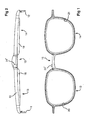
Figure 1 is a rear view of a pair of spectacles including two variable focus lens units and an actuator according to the present invention. -
Figure 2 is a top view of the spectacles ofFigure 1 . -
Figure 3 is an enlarged top sectional view of a first embodiment of the invented actuator taken at section 3-3 ofFigure 6 . The slider is shown positioned for distance viewing. -
Figure 4 is an enlarged sectional view of the invented actuator as inFigure 3 , except that the slider is positioned for intermediate distance viewing, and part of the left driving lever and cam are cut away to provide a better view of the right driving lever. -
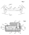
Figure 5 is an enlarged rear view of the invented actuator as shown inFigure 1 . The ends of the driving levers and cam which otherwise would be visible from the rear are omitted inFigure 5 for clarity. -
Figure 6 is a cross sectional side view of the first embodiment of the invented actuator taken at 6-6 ofFigure 5 . -
Figure 7 is a fragmentary plan view showing one style of linkage that can be used to connect a driving lever to the rear ring of a lens unit. -
Figure 8 is a fragmentary sectional side view of the linkage ofFigure 7 taken at 8-8 ofFigure 7 . -
Figure 9 is a fragmentary plan view showing a second style of linkage that can be used to connect a driving lever to a rear ring of a lens unit. -
Figure 10 is a fragmentary sectional side view of the linkage ofFigure 9 taken at 10-10 ofFigure 9 . -
Figure 11 is a fragmentary plan view showing a third style of linkage that can be used to connect a driving lever to the rear ring a lens unit. -
Figure 12 is a fragmentary sectional side view of the linkage ofFigure 11 taken at 12-12 ofFigure 11 . -
Figure 13 is an enlarged top sectional view of a second embodiment of the invented actuator, taken at 13-13 ofFigure 14 . -
Figure 14 is cross sectional view of the second embodiment of the invented actuator taken at the same section as wasFigure 6 , namely at a position corresponding to position of 6-6 ofFigure 5 . -
Figures 1 and 2 show top and rear views of a pair of variable focus spectacles in which a first embodiment of the invented actuation mechanism is installed. Primarily for cosmetic reasons, the spectacles may include acover 10 that effectively hides the mechanism from view. For clarity, thecover 10 is not shown other than inFigures 1, 2 ,6 , and14 . A fragment oftemples Figure 2 . - The spectacles are comprised of two
lens units bridge 15. The actuator of the present invention is contained within the bridge. Only so much of the construction and operation of the lens units as is deemed necessary for an understanding of the invention is included herein, but further constructional details and an explanation of lens unit operation can be found in the referenced patents (U.S. Patents 5,138,494 ,5,371,629 , and5,688,620 ). - Each lens unit contains a front ring assembly (16 and 17) that is attached by laser welding, or otherwise, to the
bridge 15.Rear ring assemblies linkage anchors -
Figures 3 and 4 are top sectional views of the invented actuator.Figure 3 shows the slider positioned for distance viewing, whileFigure 4 shows it positioned for viewing an intermediate distance. For viewing closer distances, e.g., reading distance,slider 24 would be positioned yet further to the right. Slider 24 slides alongchannel 25 in bridge 15 (as best seen inFigure 6 ). Thewearer positions slider 24 by manipulating lip 24', which is preferably a portion ofslider 24 that projects abovecover 10, where it can easily be reached and positioned by the wearer.Pin 26, which may be pressed intoslider 24, carries bushing 28 and (preferably toothed)roller 27. For long wear life, bushing 28 may, for example, be fabricated from Torlon® 4301, andpin 26 from hardened steel. Torlon® is a tradename of Solvay Advanced Polymers of Alpharetta, GA for a polyamide-imide plastic product.Roller 27 is preferably toothed to assure that it turns as the slider is moved, thereby minimizing frictional wear.Roller 27 is also preferably hardened. -
Roller 27 runs on cam surface 29' ofcam 29 and causes the cam to rotate aboutpivot pin 30 asslider 24 is moved.Pivot pin 30 is preferably pressed intobridge 15. As theslider 24 is moved to the right,cam 29 rotates counterclockwise. It will be appreciated that the directions of motion described herein are the directions corresponding to the particular embodiment illustrated, and that other embodiments may have some or all of the motions reversed. Ascam 29 rotates, drivepin 31, which is pressed through and fixedly mounted tocam 29, bears against the rear edge of left drivinglever 32 and the rear edge ofright driving lever 33. The terms "left" and "right", as applied to the driving levers, are meant to indicate which lens unit is driven by the respective drive lever. Ascam 29 rotates counterclockwise (about the pin 30), right drivinglever 33 rotates also counterclockwise aboutpivot pin 30. At the same time, left drivinglever 32 rotates clockwise aboutpivot pin 34. The right hand portions ofcam 29 and left drivinglever 32 are cut away inFigure 4 so that right drivinglever 33 can be clearly seen. - As seen in the figures, the cam surface 29' appears straight. However, this surface may be straight, or it may be curved gently (thereby altering the shape of the functional relationship between cam rotation and slider position). For example, it may be desired that the change in optical power with respect to change in slider position be lower near the distance viewing position of the slider than near the reading position of the slider. Changing the shape of cam surface 29' can accomplish that objective.
- In the embodiment of the invention shown in
Figures 3 and 4 , the free ends of drivinglevers ribbon lever 33 andlinkage anchor 23 shown inFigures 7 and 8 illustrate the connection. The ribbon is shown stippled inFigure 8 for clarity. It will be appreciated that each lens unit includes liquid under pressure, and therefore the lens units provide an inherent restoring force. Hence only a unidirectional actuating force (i.e., pulling) need be applied. The ribbon strips are preferably fabricated from high strength steel. The size of the ribbon section will depend on many factors in the design of the spectacles. One end of a ribbon may, for example, be laser or spot welded to the free end of a driving lever, and the other end similarly welded to the corresponding linkage anchor. As shown, each ribbon is attached to a linkage anchor (22 or 23) extending from the rear rings. The illustrated construction is a matter of convenience. Each ribbon could alternatively be attached directly to a rear ring, and in that case, linkage anchors would not used. - There are many other possible configurations for the links between the driving levers and the rear rings. Two such alternate configurations are illustrated in
figures 9 through 12 . InFigures 9 and 10 , a wire 36', preferably having a round cross-section, is shown looped over the driving lever 33', and laser welded to linkage anchor 23'. InFigures 11 and 12 ahook 36", fabricated from a metal strip, is hooked over drivinglever 33" and laser welded tolinkage anchor 23". Other configurations are also possible, as will be appreciated by those skilled in the art. - Installing the linkages between driving levers and the lens units is preferably the last step in the production of the spectacles prior to final filling with optical fluid. Various methods of installing the links are possible; an illustration of a presently preferred method of installation is described below. For convenience of description, all reference is explicitly to ribbon links. It will be understood, however, that other types of link may be installed using similar procedures.
- First, a length of ribbon longer than is ultimately required is welded to each driving lever tip. The
slider 24 is positioned to its closest view position using lip 24' (all the way to the right as seen inFigures 1 and 2 ). The rear ring assembly of each lens unit is then rotated maximally forward, for example by applying a force on the rear ring near the corresponding linkage anchor. Rearward tension is applied to each ribbon, and it is welded to the appropriate linkage anchor. Excess ribbon may be cut off, and the installation is then complete. - After the linkages are installed, the lens units may be filled with liquid. For this operation, the slider is positioned for distance viewing (all the way to the left) and liquid is injected into each lens unit until the lens focal length is the desired value for distance viewing. This portion of the manufacturing process is then complete.
- A second embodiment of the invention is illustrated in
Figures 13 and 14 . The second embodiment requires fewer parts than the first embodiment, however, the first embodiment has the advantage that the driving levers can be made symmetrical, and if so made, displacement errors due to bending of the driving levers tend to balance out. The parts of the second embodiment that are substantially identical to the corresponding parts of the first embodiment are given the same numeric designation as the first embodiment parts. The difference between the two embodiments resides only in that theright driving lever 33 and thecam 29 of the first embodiment are combined into one part, cam/drivinglever 50. Left drivinglever 32 is shown broken away inFigure 13 so that cam/drivinglever 50 may be clearly seen. Left drivinglever 32 rotates aboutpivot pin 34 while the cam/drivinglever 50 rotates aboutpivot pin 30.Pin 31, pressed through cam/drivinglever 50drives driving lever 32 clockwise as the cam/driving lever is rotated counterclockwise. - Two embodiments of the invented actuator have been described above but those skilled in the art will no doubt appreciate that other embodiments and variants of the above embodiments are possible within the following claims.
Claims (15)
- An actuation mechanism for spectacles which include two variable focus lens units (13,14) and a bridge (15) therebetween, said actuation mechanism comprising:a rotatable cam (29) mounted near one end of said bridge, said cam having a cam surface (29');a manually operable sliding member (24) mounted for linear motion along the length of said bridge and engaging said cam surface to cause said cam to rotate as said sliding member is moved;first and second elongated driving levers (32, 33); andmeans (31) for coupling said cam to said driving levers whereby rotation of said cam will cause said driving levers to rotate in opposite directions, characterised by said driving levers being rotatably mounted near each end of said bridge for rotation upon cam actuation, each of said driving levers extending toward the end of said bridge most remote from its point of mounting and having a free end; and byfirst and second linkages (35,36), each coupling said free end of one of said driving levers to one of said variable focus lens units.
- An actuation mechanism as recited in claim 1 wherein each of said first and second elongated driving levers (32, 33), and said first and second linkages (35, 36), are a pair.
- An actuation mechanism as recited in claim 1 wherein said cam (29) rotates about the same axis as one of said driving levers (32, 33).
- An actuation mechanism as recited in claim 2 wherein said cam (29) is positioned between said driving levers (32, 33).
- An actuation mechanism as recited in claim 1, including first and second pins (30, 34) attached to said bridge (15) near opposite ends thereof, wherein said first and second elongated driving levers (32, 33) are each mounted on one of said pins and free to rotate thereabout, each of said driving levers extending toward the end of said bridge furthest from the pin on which it is mounted, said cam (29) being disposed between said first and second elongated driving levers, said means (31) for coupling being arranged to cause said cam to engage said driving levers for causing said rotation in opposite directions.
- An actuation mechanism as recited in claim 5 wherein said cam is arranged to (29) rotate about said first pin (30).
- An actuation mechanism for spectacles which include, two variable focus lens units (13, 14) and a bridge (15) therebetween, said actuation mechanism comprising:a rotatable combined can and driving lever (50) mounted near one end of said bridge, said combined can and driving lever having a cam surface (29');a manually operable sliding member (24) mounted for linear motion along the length of said bridge and engaging said cam surface to cause said combined can and driving lever to rotate as said sliding member is moved;an elongated driving lever (32); andmeans (31) for coupling said combined can and driving lever to said driving lever whereby rotation of said combined can and driving lever will cause said driving lever to rotate in an opposite direction, said combined can and driving lever and said driving lever being rotatably mounted near each end of said bridge for rotation upon combined can and driving lever actuation, each of said combined can and driving lever and driving lever extending toward the end of said bridge most remote from its point of mounting and having a free end; and byfirst and second linkages (35,36), each coupling said free end of one of said combined can and driving lever and driving lever to one of said variable focus lens units.
- An actuation mechanism as recited in either one of claims 1 and 7 wherein said sliding member (24) includes a user accessible lip (24') located above said bridge (15).
- An actuation mechanism as recited in either one of claims 1 and 7 wherein said linkages (35, 36) are comprised of thin pieces of ribbon fastened to said driving levers (32, 33) or said combined can and driving lever (50) and said driving lever (32), and to said lens units (13, 14).
- An actuation mechanism as recited in claim 9 wherein said pieces of ribbon (35, 36) are fastened to said driving levers (32, 33) or said combined can and driving lever (50) and said driving lever (32), and to said lens units (13, 14) by welding.
- An actuation mechanism as recited in claim 1 or claim 7 wherein said linkages (35, 36) are looped over said driving levers (32, 33) or over said combined can and driving lever (50) and said driving lever (32).
- An actuation mechanism as recited in claim 11 wherein said linkages (35, 36) are comprised of wire.
- An actuation mechanism as recited in either one of claims 1 and 7 wherein said cam surface (29') is straight.
- An actuation mechanism as recited in either one of claims 1 and 7 wherein said cam surface (29') is curved.
- An actuation mechanism as claimed in any preceding claim in which said driving levers (32, 33), or said combined can and driving lever (50) and said driving lever (32), are rotatably mounted to said bridge (15).
Applications Claiming Priority (2)
| Application Number | Priority Date | Filing Date | Title |
|---|---|---|---|
| US10/993,804 US7008054B1 (en) | 2004-11-20 | 2004-11-20 | Actuation mechanism for variable focus spectacles |
| PCT/US2005/040562 WO2006055366A1 (en) | 2004-11-20 | 2005-11-10 | Actuation mechanism for variable focus spectacles |
Publications (3)
| Publication Number | Publication Date |
|---|---|
| EP1812818A1 EP1812818A1 (en) | 2007-08-01 |
| EP1812818A4 EP1812818A4 (en) | 2009-04-15 |
| EP1812818B1 true EP1812818B1 (en) | 2011-03-30 |
Family
ID=35966145
Family Applications (1)
| Application Number | Title | Priority Date | Filing Date |
|---|---|---|---|
| EP05818683A Expired - Lifetime EP1812818B1 (en) | 2004-11-20 | 2005-11-10 | Actuation mechanism for variable focus spectacles |
Country Status (7)
| Country | Link |
|---|---|
| US (1) | US7008054B1 (en) |
| EP (1) | EP1812818B1 (en) |
| JP (1) | JP4787264B2 (en) |
| AT (1) | ATE504025T1 (en) |
| CA (1) | CA2587900C (en) |
| DE (1) | DE602005027236D1 (en) |
| WO (1) | WO2006055366A1 (en) |
Families Citing this family (56)
| Publication number | Priority date | Publication date | Assignee | Title |
|---|---|---|---|---|
| US6986579B2 (en) * | 1999-07-02 | 2006-01-17 | E-Vision, Llc | Method of manufacturing an electro-active lens |
| US6619799B1 (en) | 1999-07-02 | 2003-09-16 | E-Vision, Llc | Optical lens system with electro-active lens having alterably different focal lengths |
| US7023594B2 (en) * | 2000-06-23 | 2006-04-04 | E-Vision, Llc | Electro-optic lens with integrated components |
| US6871951B2 (en) * | 2000-06-23 | 2005-03-29 | E-Vision, Llc | Electro-optic lens with integrated components |
| US6857741B2 (en) * | 2002-01-16 | 2005-02-22 | E-Vision, Llc | Electro-active multi-focal spectacle lens |
| US20090103044A1 (en) * | 1999-07-02 | 2009-04-23 | Duston Dwight P | Spectacle frame bridge housing electronics for electro-active spectacle lenses |
| US7404636B2 (en) | 1999-07-02 | 2008-07-29 | E-Vision, Llc | Electro-active spectacle employing modal liquid crystal lenses |
| US20070258039A1 (en) * | 1999-07-02 | 2007-11-08 | Duston Dwight P | Spectacle frame bridge housing electronics for electro-active spectacle lenses |
| US7290875B2 (en) | 2004-11-02 | 2007-11-06 | Blum Ronald D | Electro-active spectacles and method of fabricating same |
| US7775660B2 (en) * | 1999-07-02 | 2010-08-17 | E-Vision Llc | Electro-active ophthalmic lens having an optical power blending region |
| US7988286B2 (en) | 1999-07-02 | 2011-08-02 | E-Vision Llc | Static progressive surface region in optical communication with a dynamic optic |
| US7604349B2 (en) * | 1999-07-02 | 2009-10-20 | E-Vision, Llc | Static progressive surface region in optical communication with a dynamic optic |
| US20080106633A1 (en) * | 2002-03-13 | 2008-05-08 | Blum Ronald D | Electro-optic lens with integrated components for varying refractive properties |
| CA2535905A1 (en) | 2003-08-15 | 2005-02-24 | E-Vision, Llc | Enhanced electro-active lens system |
| US20050237485A1 (en) * | 2004-04-21 | 2005-10-27 | Blum Ronald D | Method and apparatus for correcting vision |
| US9801709B2 (en) | 2004-11-02 | 2017-10-31 | E-Vision Smart Optics, Inc. | Electro-active intraocular lenses |
| US8915588B2 (en) | 2004-11-02 | 2014-12-23 | E-Vision Smart Optics, Inc. | Eyewear including a heads up display |
| US8778022B2 (en) | 2004-11-02 | 2014-07-15 | E-Vision Smart Optics Inc. | Electro-active intraocular lenses |
| BRPI0518058A (en) * | 2004-11-02 | 2008-10-28 | E-Vision Llc | electro-spectacles and manufacturing methods |
| US20070159562A1 (en) * | 2006-01-10 | 2007-07-12 | Haddock Joshua N | Device and method for manufacturing an electro-active spectacle lens involving a mechanically flexible integration insert |
| US20080273166A1 (en) | 2007-05-04 | 2008-11-06 | William Kokonaski | Electronic eyeglass frame |
| WO2008105780A2 (en) | 2006-05-24 | 2008-09-04 | Pixeloptics, Inc. | Optical rangefinder for an electro-active lens |
| CA2656267A1 (en) * | 2006-06-23 | 2008-01-03 | Pixeloptics, Inc. | Electronic adapter for electro-active spectacle lenses |
| US7866816B2 (en) * | 2006-10-10 | 2011-01-11 | Lane Research, Llc | Variable focus spectacles |
| US20080100792A1 (en) * | 2006-10-27 | 2008-05-01 | Blum Ronald D | Universal endpiece for spectacle temples |
| AR064985A1 (en) | 2007-01-22 | 2009-05-06 | E Vision Llc | FLEXIBLE ELECTROACTIVE LENS |
| AU2008218240B2 (en) * | 2007-02-23 | 2014-01-30 | E-Vision Smart Optics, Inc. | Ophthalmic dynamic aperture |
| US20080273169A1 (en) * | 2007-03-29 | 2008-11-06 | Blum Ronald D | Multifocal Lens Having a Progressive Optical Power Region and a Discontinuity |
| US7883207B2 (en) * | 2007-12-14 | 2011-02-08 | Pixeloptics, Inc. | Refractive-diffractive multifocal lens |
| US20090091818A1 (en) * | 2007-10-05 | 2009-04-09 | Haddock Joshua N | Electro-active insert |
| US7883206B2 (en) | 2007-03-07 | 2011-02-08 | Pixeloptics, Inc. | Multifocal lens having a progressive optical power region and a discontinuity |
| US11061252B2 (en) | 2007-05-04 | 2021-07-13 | E-Vision, Llc | Hinge for electronic spectacles |
| US12572035B2 (en) | 2007-05-04 | 2026-03-10 | E-Vision Optics, Llc | Moisture-resistant eye wear |
| US10613355B2 (en) | 2007-05-04 | 2020-04-07 | E-Vision, Llc | Moisture-resistant eye wear |
| US8317321B2 (en) * | 2007-07-03 | 2012-11-27 | Pixeloptics, Inc. | Multifocal lens with a diffractive optical power region |
| BRPI0908992A2 (en) | 2008-03-18 | 2015-11-24 | Pixeloptics Inc | advanced electro-active optical device |
| US8154804B2 (en) * | 2008-03-25 | 2012-04-10 | E-Vision Smart Optics, Inc. | Electro-optic lenses for correction of higher order aberrations |
| JP5408647B2 (en) * | 2008-12-12 | 2014-02-05 | スカラ株式会社 | Glasses and glasses vertical position adjustment device |
| MX2012013533A (en) | 2010-05-24 | 2013-01-24 | Pixeloptics Inc | Reduction of image jump. |
| US12436411B2 (en) | 2010-07-02 | 2025-10-07 | E-Vision Optics, Llc | Moisture-resistant eye wear |
| TW201234072A (en) | 2010-11-01 | 2012-08-16 | Pixeloptics Inc | Dynamic changeable focus contact and intraocular lens |
| US12510773B2 (en) | 2011-02-11 | 2025-12-30 | E-Vision Optics, Llc | Moisture-resistant eye wear |
| JP6035255B2 (en) | 2011-03-17 | 2016-11-30 | カール ツアイス メディテック アクチエンゲゼルシャフト | System and method for refraction correction in visual field inspection |
| KR102276220B1 (en) | 2012-01-06 | 2021-07-13 | 이-비전 스마트 옵틱스, 아이엔씨. | Eyewear docking station and electronic module |
| WO2013104003A1 (en) * | 2012-01-08 | 2013-07-11 | Zoom Focus Eyewear LLC dba Superfocus LLC | Rotary actuation mechanism for variable focus spectacles |
| WO2014026153A1 (en) | 2012-08-10 | 2014-02-13 | Pixeloptics, Inc. | Dynamic ophthalmic lens capable of correcting night and day vision |
| GB201301764D0 (en) * | 2013-01-31 | 2013-03-20 | Adlens Ltd | Actuation of fluid-filled lenses |
| RU2599181C2 (en) * | 2015-01-12 | 2016-10-10 | Владимир Леонтьевич Крапивин | Eyeglasses with length-calibrated bridge (gcb) |
| WO2017059381A1 (en) | 2015-10-02 | 2017-04-06 | Stephen Kurtin | Adjustable focus spectacles with non-circular lenses |
| US10599006B2 (en) | 2016-04-12 | 2020-03-24 | E-Vision Smart Optics, Inc. | Electro-active lenses with raised resistive bridges |
| ES2861520T3 (en) | 2016-04-12 | 2021-10-06 | E Vision Smart Optics Inc | Electroactive lenses with high resistive bridges |
| US10261343B2 (en) | 2016-12-29 | 2019-04-16 | Valdemar Portney | Frame independent focus adjustable eyewear lens |
| US11409129B2 (en) * | 2017-10-31 | 2022-08-09 | Expression Frames LLC | Modular eyeglass frame apparatus and system |
| US10962791B1 (en) | 2018-03-22 | 2021-03-30 | Facebook Technologies, Llc | Apparatuses, systems, and methods for fabricating ultra-thin adjustable lenses |
| US11245065B1 (en) | 2018-03-22 | 2022-02-08 | Facebook Technologies, Llc | Electroactive polymer devices, systems, and methods |
| US10914871B2 (en) | 2018-03-29 | 2021-02-09 | Facebook Technologies, Llc | Optical lens assemblies and related methods |
Family Cites Families (9)
| Publication number | Priority date | Publication date | Assignee | Title |
|---|---|---|---|---|
| US5138494A (en) | 1990-05-07 | 1992-08-11 | Stephen Kurtin | Variable focal length lens |
| US5229885A (en) * | 1991-09-03 | 1993-07-20 | Quaglia Lawrence D | Infinitely variable focal power lens units precisely matched to varying distances by radar and electronics |
| US5371629A (en) | 1993-02-04 | 1994-12-06 | Kurtin; Stephen | Non-circular variable focus lens |
| US5668620A (en) | 1994-04-12 | 1997-09-16 | Kurtin; Stephen | Variable focal length lenses which have an arbitrarily shaped periphery |
| US5999328A (en) * | 1994-11-08 | 1999-12-07 | Kurtin; Stephen | Liquid-filled variable focus lens with band actuator |
| US5526067A (en) * | 1994-12-21 | 1996-06-11 | Polaroid Corporation | Actuation mechanism for variable focal length eyeglasses |
| JP3184741B2 (en) | 1995-05-24 | 2001-07-09 | シャープ株式会社 | Electrophotographic photoreceptor |
| US5956183A (en) * | 1998-05-26 | 1999-09-21 | Epstein; Saul | Field-customizable variable focal length lens |
| US6053610A (en) | 1999-07-15 | 2000-04-25 | Lane Research | Actuation mechanism for variable focal length spectacles |
-
2004
- 2004-11-20 US US10/993,804 patent/US7008054B1/en not_active Expired - Fee Related
-
2005
- 2005-11-10 DE DE602005027236T patent/DE602005027236D1/en not_active Expired - Lifetime
- 2005-11-10 AT AT05818683T patent/ATE504025T1/en not_active IP Right Cessation
- 2005-11-10 WO PCT/US2005/040562 patent/WO2006055366A1/en not_active Ceased
- 2005-11-10 EP EP05818683A patent/EP1812818B1/en not_active Expired - Lifetime
- 2005-11-10 CA CA2587900A patent/CA2587900C/en not_active Expired - Fee Related
- 2005-11-10 JP JP2007543120A patent/JP4787264B2/en not_active Expired - Fee Related
Also Published As
| Publication number | Publication date |
|---|---|
| ATE504025T1 (en) | 2011-04-15 |
| JP4787264B2 (en) | 2011-10-05 |
| WO2006055366A1 (en) | 2006-05-26 |
| US7008054B1 (en) | 2006-03-07 |
| EP1812818A1 (en) | 2007-08-01 |
| JP2008521058A (en) | 2008-06-19 |
| EP1812818A4 (en) | 2009-04-15 |
| CA2587900A1 (en) | 2006-05-26 |
| CA2587900C (en) | 2014-10-07 |
| DE602005027236D1 (en) | 2011-05-12 |
Similar Documents
| Publication | Publication Date | Title |
|---|---|---|
| CA2587900C (en) | Actuation mechanism for variable focus spectacles | |
| US5999328A (en) | Liquid-filled variable focus lens with band actuator | |
| TW459152B (en) | Actuation mechanism for spectacles | |
| US20130141692A1 (en) | Eyeglasses and means for their adjustment | |
| WO1996019748A1 (en) | An actuation mechanism for variable focal length eyeglasses | |
| JP2008286884A (en) | Multi-focus spectacle frame | |
| JPH10133153A (en) | Temple joint structure of spectacle frame | |
| JP6038943B2 (en) | Adjustable glasses | |
| KR20120030914A (en) | Flip-up and down glasses including a spring-loaded cam-hinge mechanism | |
| EP2591392A1 (en) | Spectacles frame side with changeable curvature | |
| JP3885072B2 (en) | Eyeglass frame and lens hanger | |
| US8888276B2 (en) | Rotary actuation mechanism for variable focus spectacles | |
| JP3197473U (en) | glasses | |
| KR20210000138U (en) | Frames for glasses | |
| JP3109519U (en) | Front glasses | |
| CN222762345U (en) | Temple assembly and flippable glasses | |
| JP3771564B2 (en) | Glasses hinge structure and glasses with this hinge structure | |
| JPH10206803A (en) | Bifocal spectacle frame | |
| CN101673022B (en) | Focusing module | |
| EP1662294A1 (en) | Eyeglasses comprising temples articulated through bores | |
| WO2022180819A1 (en) | Spectacles | |
| US20190274412A1 (en) | Makeup application device | |
| JP2001324701A (en) | Hinge connecting mechanism of temple | |
| JPH09211395A (en) | Eyeglass frames | |
| JP2002341295A (en) | Rimless glasses device |
Legal Events
| Date | Code | Title | Description |
|---|---|---|---|
| PUAI | Public reference made under article 153(3) epc to a published international application that has entered the european phase |
Free format text: ORIGINAL CODE: 0009012 |
|
| 17P | Request for examination filed |
Effective date: 20070503 |
|
| AK | Designated contracting states |
Kind code of ref document: A1 Designated state(s): AT BE BG CH CY CZ DE DK EE ES FI FR GB GR HU IE IS IT LI LT LU LV MC NL PL PT RO SE SI SK TR |
|
| DAX | Request for extension of the european patent (deleted) | ||
| RIC1 | Information provided on ipc code assigned before grant |
Ipc: G02C 7/08 20060101ALI20090227BHEP Ipc: G02C 5/00 20060101AFI20061030BHEP |
|
| A4 | Supplementary search report drawn up and despatched |
Effective date: 20090317 |
|
| 17Q | First examination report despatched |
Effective date: 20090707 |
|
| GRAP | Despatch of communication of intention to grant a patent |
Free format text: ORIGINAL CODE: EPIDOSNIGR1 |
|
| GRAS | Grant fee paid |
Free format text: ORIGINAL CODE: EPIDOSNIGR3 |
|
| GRAA | (expected) grant |
Free format text: ORIGINAL CODE: 0009210 |
|
| AK | Designated contracting states |
Kind code of ref document: B1 Designated state(s): AT BE BG CH CY CZ DE DK EE ES FI FR GB GR HU IE IS IT LI LT LU LV MC NL PL PT RO SE SI SK TR |
|
| REG | Reference to a national code |
Ref country code: GB Ref legal event code: FG4D |
|
| REG | Reference to a national code |
Ref country code: CH Ref legal event code: EP |
|
| REG | Reference to a national code |
Ref country code: IE Ref legal event code: FG4D |
|
| REF | Corresponds to: |
Ref document number: 602005027236 Country of ref document: DE Date of ref document: 20110512 Kind code of ref document: P |
|
| REG | Reference to a national code |
Ref country code: DE Ref legal event code: R096 Ref document number: 602005027236 Country of ref document: DE Effective date: 20110512 |
|
| REG | Reference to a national code |
Ref country code: NL Ref legal event code: VDEP Effective date: 20110330 |
|
| PG25 | Lapsed in a contracting state [announced via postgrant information from national office to epo] |
Ref country code: GR Free format text: LAPSE BECAUSE OF FAILURE TO SUBMIT A TRANSLATION OF THE DESCRIPTION OR TO PAY THE FEE WITHIN THE PRESCRIBED TIME-LIMIT Effective date: 20110701 Ref country code: LT Free format text: LAPSE BECAUSE OF FAILURE TO SUBMIT A TRANSLATION OF THE DESCRIPTION OR TO PAY THE FEE WITHIN THE PRESCRIBED TIME-LIMIT Effective date: 20110330 Ref country code: SE Free format text: LAPSE BECAUSE OF FAILURE TO SUBMIT A TRANSLATION OF THE DESCRIPTION OR TO PAY THE FEE WITHIN THE PRESCRIBED TIME-LIMIT Effective date: 20110330 Ref country code: LV Free format text: LAPSE BECAUSE OF FAILURE TO SUBMIT A TRANSLATION OF THE DESCRIPTION OR TO PAY THE FEE WITHIN THE PRESCRIBED TIME-LIMIT Effective date: 20110330 |
|
| LTIE | Lt: invalidation of european patent or patent extension |
Effective date: 20110330 |
|
| PG25 | Lapsed in a contracting state [announced via postgrant information from national office to epo] |
Ref country code: AT Free format text: LAPSE BECAUSE OF FAILURE TO SUBMIT A TRANSLATION OF THE DESCRIPTION OR TO PAY THE FEE WITHIN THE PRESCRIBED TIME-LIMIT Effective date: 20110330 Ref country code: CY Free format text: LAPSE BECAUSE OF FAILURE TO SUBMIT A TRANSLATION OF THE DESCRIPTION OR TO PAY THE FEE WITHIN THE PRESCRIBED TIME-LIMIT Effective date: 20110330 Ref country code: SI Free format text: LAPSE BECAUSE OF FAILURE TO SUBMIT A TRANSLATION OF THE DESCRIPTION OR TO PAY THE FEE WITHIN THE PRESCRIBED TIME-LIMIT Effective date: 20110330 Ref country code: FI Free format text: LAPSE BECAUSE OF FAILURE TO SUBMIT A TRANSLATION OF THE DESCRIPTION OR TO PAY THE FEE WITHIN THE PRESCRIBED TIME-LIMIT Effective date: 20110330 |
|
| PG25 | Lapsed in a contracting state [announced via postgrant information from national office to epo] |
Ref country code: BE Free format text: LAPSE BECAUSE OF FAILURE TO SUBMIT A TRANSLATION OF THE DESCRIPTION OR TO PAY THE FEE WITHIN THE PRESCRIBED TIME-LIMIT Effective date: 20110330 |
|
| PG25 | Lapsed in a contracting state [announced via postgrant information from national office to epo] |
Ref country code: EE Free format text: LAPSE BECAUSE OF FAILURE TO SUBMIT A TRANSLATION OF THE DESCRIPTION OR TO PAY THE FEE WITHIN THE PRESCRIBED TIME-LIMIT Effective date: 20110330 Ref country code: PT Free format text: LAPSE BECAUSE OF FAILURE TO SUBMIT A TRANSLATION OF THE DESCRIPTION OR TO PAY THE FEE WITHIN THE PRESCRIBED TIME-LIMIT Effective date: 20110801 |
|
| PG25 | Lapsed in a contracting state [announced via postgrant information from national office to epo] |
Ref country code: ES Free format text: LAPSE BECAUSE OF FAILURE TO SUBMIT A TRANSLATION OF THE DESCRIPTION OR TO PAY THE FEE WITHIN THE PRESCRIBED TIME-LIMIT Effective date: 20110711 Ref country code: RO Free format text: LAPSE BECAUSE OF FAILURE TO SUBMIT A TRANSLATION OF THE DESCRIPTION OR TO PAY THE FEE WITHIN THE PRESCRIBED TIME-LIMIT Effective date: 20110330 Ref country code: SK Free format text: LAPSE BECAUSE OF FAILURE TO SUBMIT A TRANSLATION OF THE DESCRIPTION OR TO PAY THE FEE WITHIN THE PRESCRIBED TIME-LIMIT Effective date: 20110330 Ref country code: IS Free format text: LAPSE BECAUSE OF FAILURE TO SUBMIT A TRANSLATION OF THE DESCRIPTION OR TO PAY THE FEE WITHIN THE PRESCRIBED TIME-LIMIT Effective date: 20110730 Ref country code: CZ Free format text: LAPSE BECAUSE OF FAILURE TO SUBMIT A TRANSLATION OF THE DESCRIPTION OR TO PAY THE FEE WITHIN THE PRESCRIBED TIME-LIMIT Effective date: 20110330 |
|
| PG25 | Lapsed in a contracting state [announced via postgrant information from national office to epo] |
Ref country code: NL Free format text: LAPSE BECAUSE OF FAILURE TO SUBMIT A TRANSLATION OF THE DESCRIPTION OR TO PAY THE FEE WITHIN THE PRESCRIBED TIME-LIMIT Effective date: 20110330 |
|
| PGFP | Annual fee paid to national office [announced via postgrant information from national office to epo] |
Ref country code: FR Payment date: 20111213 Year of fee payment: 7 |
|
| PLBE | No opposition filed within time limit |
Free format text: ORIGINAL CODE: 0009261 |
|
| STAA | Information on the status of an ep patent application or granted ep patent |
Free format text: STATUS: NO OPPOSITION FILED WITHIN TIME LIMIT |
|
| PG25 | Lapsed in a contracting state [announced via postgrant information from national office to epo] |
Ref country code: DK Free format text: LAPSE BECAUSE OF FAILURE TO SUBMIT A TRANSLATION OF THE DESCRIPTION OR TO PAY THE FEE WITHIN THE PRESCRIBED TIME-LIMIT Effective date: 20110330 Ref country code: PL Free format text: LAPSE BECAUSE OF FAILURE TO SUBMIT A TRANSLATION OF THE DESCRIPTION OR TO PAY THE FEE WITHIN THE PRESCRIBED TIME-LIMIT Effective date: 20110330 |
|
| 26N | No opposition filed |
Effective date: 20120102 |
|
| REG | Reference to a national code |
Ref country code: DE Ref legal event code: R097 Ref document number: 602005027236 Country of ref document: DE Effective date: 20120102 |
|
| PG25 | Lapsed in a contracting state [announced via postgrant information from national office to epo] |
Ref country code: IT Free format text: LAPSE BECAUSE OF FAILURE TO SUBMIT A TRANSLATION OF THE DESCRIPTION OR TO PAY THE FEE WITHIN THE PRESCRIBED TIME-LIMIT Effective date: 20110330 |
|
| PG25 | Lapsed in a contracting state [announced via postgrant information from national office to epo] |
Ref country code: MC Free format text: LAPSE BECAUSE OF NON-PAYMENT OF DUE FEES Effective date: 20111130 |
|
| REG | Reference to a national code |
Ref country code: CH Ref legal event code: PL |
|
| PG25 | Lapsed in a contracting state [announced via postgrant information from national office to epo] |
Ref country code: LI Free format text: LAPSE BECAUSE OF NON-PAYMENT OF DUE FEES Effective date: 20111130 Ref country code: CH Free format text: LAPSE BECAUSE OF NON-PAYMENT OF DUE FEES Effective date: 20111130 |
|
| REG | Reference to a national code |
Ref country code: IE Ref legal event code: MM4A |
|
| PG25 | Lapsed in a contracting state [announced via postgrant information from national office to epo] |
Ref country code: IE Free format text: LAPSE BECAUSE OF NON-PAYMENT OF DUE FEES Effective date: 20111110 |
|
| PG25 | Lapsed in a contracting state [announced via postgrant information from national office to epo] |
Ref country code: LU Free format text: LAPSE BECAUSE OF NON-PAYMENT OF DUE FEES Effective date: 20111110 |
|
| PG25 | Lapsed in a contracting state [announced via postgrant information from national office to epo] |
Ref country code: BG Free format text: LAPSE BECAUSE OF FAILURE TO SUBMIT A TRANSLATION OF THE DESCRIPTION OR TO PAY THE FEE WITHIN THE PRESCRIBED TIME-LIMIT Effective date: 20110630 |
|
| GBPC | Gb: european patent ceased through non-payment of renewal fee |
Effective date: 20121110 |
|
| REG | Reference to a national code |
Ref country code: FR Ref legal event code: ST Effective date: 20130731 |
|
| REG | Reference to a national code |
Ref country code: DE Ref legal event code: R119 Ref document number: 602005027236 Country of ref document: DE Effective date: 20130601 |
|
| PG25 | Lapsed in a contracting state [announced via postgrant information from national office to epo] |
Ref country code: TR Free format text: LAPSE BECAUSE OF FAILURE TO SUBMIT A TRANSLATION OF THE DESCRIPTION OR TO PAY THE FEE WITHIN THE PRESCRIBED TIME-LIMIT Effective date: 20110330 |
|
| PG25 | Lapsed in a contracting state [announced via postgrant information from national office to epo] |
Ref country code: DE Free format text: LAPSE BECAUSE OF NON-PAYMENT OF DUE FEES Effective date: 20130601 Ref country code: HU Free format text: LAPSE BECAUSE OF FAILURE TO SUBMIT A TRANSLATION OF THE DESCRIPTION OR TO PAY THE FEE WITHIN THE PRESCRIBED TIME-LIMIT Effective date: 20110330 |
|
| PG25 | Lapsed in a contracting state [announced via postgrant information from national office to epo] |
Ref country code: GB Free format text: LAPSE BECAUSE OF NON-PAYMENT OF DUE FEES Effective date: 20121110 Ref country code: FR Free format text: LAPSE BECAUSE OF NON-PAYMENT OF DUE FEES Effective date: 20121130 |