EP1811723A1 - Self annealing auto-expanding network - Google Patents
Self annealing auto-expanding network Download PDFInfo
- Publication number
- EP1811723A1 EP1811723A1 EP07000907A EP07000907A EP1811723A1 EP 1811723 A1 EP1811723 A1 EP 1811723A1 EP 07000907 A EP07000907 A EP 07000907A EP 07000907 A EP07000907 A EP 07000907A EP 1811723 A1 EP1811723 A1 EP 1811723A1
- Authority
- EP
- European Patent Office
- Prior art keywords
- node
- network
- ring
- circuit
- coupled
- Prior art date
- Legal status (The legal status is an assumption and is not a legal conclusion. Google has not performed a legal analysis and makes no representation as to the accuracy of the status listed.)
- Granted
Links
Images





Classifications
-
- H—ELECTRICITY
- H04—ELECTRIC COMMUNICATION TECHNIQUE
- H04Q—SELECTING
- H04Q3/00—Selecting arrangements
- H04Q3/0016—Arrangements providing connection between exchanges
- H04Q3/0062—Provisions for network management
- H04Q3/0075—Fault management techniques
- H04Q3/0079—Fault management techniques involving restoration of networks, e.g. disaster recovery, self-healing networks
-
- H—ELECTRICITY
- H04—ELECTRIC COMMUNICATION TECHNIQUE
- H04L—TRANSMISSION OF DIGITAL INFORMATION, e.g. TELEGRAPHIC COMMUNICATION
- H04L12/00—Data switching networks
- H04L12/28—Data switching networks characterised by path configuration, e.g. LAN [Local Area Networks] or WAN [Wide Area Networks]
- H04L12/42—Loop networks
-
- H—ELECTRICITY
- H04—ELECTRIC COMMUNICATION TECHNIQUE
- H04L—TRANSMISSION OF DIGITAL INFORMATION, e.g. TELEGRAPHIC COMMUNICATION
- H04L12/00—Data switching networks
- H04L12/28—Data switching networks characterised by path configuration, e.g. LAN [Local Area Networks] or WAN [Wide Area Networks]
- H04L12/42—Loop networks
- H04L12/437—Ring fault isolation or reconfiguration
-
- H—ELECTRICITY
- H04—ELECTRIC COMMUNICATION TECHNIQUE
- H04L—TRANSMISSION OF DIGITAL INFORMATION, e.g. TELEGRAPHIC COMMUNICATION
- H04L12/00—Data switching networks
- H04L12/28—Data switching networks characterised by path configuration, e.g. LAN [Local Area Networks] or WAN [Wide Area Networks]
- H04L12/46—Interconnection of networks
- H04L12/4637—Interconnected ring systems
-
- H—ELECTRICITY
- H04—ELECTRIC COMMUNICATION TECHNIQUE
- H04Q—SELECTING
- H04Q2213/00—Indexing scheme relating to selecting arrangements in general and for multiplex systems
- H04Q2213/13166—Fault prevention
-
- H—ELECTRICITY
- H04—ELECTRIC COMMUNICATION TECHNIQUE
- H04Q—SELECTING
- H04Q2213/00—Indexing scheme relating to selecting arrangements in general and for multiplex systems
- H04Q2213/13335—Simulation, emulation
-
- H—ELECTRICITY
- H04—ELECTRIC COMMUNICATION TECHNIQUE
- H04Q—SELECTING
- H04Q2213/00—Indexing scheme relating to selecting arrangements in general and for multiplex systems
- H04Q2213/13342—Arrangement of switches in the network
-
- H—ELECTRICITY
- H04—ELECTRIC COMMUNICATION TECHNIQUE
- H04Q—SELECTING
- H04Q2213/00—Indexing scheme relating to selecting arrangements in general and for multiplex systems
- H04Q2213/13349—Network management
Definitions
- the invention relates to networks, and more particularly, to a system that connects two or more devices.
- Networks allow computers to communicate. Networks sometimes establish a cohesive architecture that allows different equipment to transfer information in a near-seamless fashion. There are several ways to physically connect computers including daisy chain and ring topologies.
- a daisy chain connects devices in series. To minimize conflicting communication requests; each device in some daisy chains may be given a different priority, in other daisy chains a device may monitor a communication channel and transmit when an exchange ends.
- a ring network devices are connected in a closed loop or a ring. Messages are passed around the ring from one node to the next in one direction. When a node receives a message it examines the destination address attached to the message and accepts it or passes the message to the next node.
- a ring based network comprises a first circuit and a second circuit.
- the first circuit selects one of a number of inputs and switches an input to a first common communication line.
- a second circuit selects one of a second number of inputs and switches a second input to a second common communication line linked to one of the first number of inputs.
- a detect circuit controls the switches of the first and second circuit to emulate a communication ring in which nodes are connected in series in a communication loop.
- Figure 1 is a block diagram of an interface adapter.
- Figure 2 is a second block diagram of the interface adapter of figure 1.
- FIG. 3 is block diagram of an alternative interface adapter.
- Figure 4 is a block diagram of a two node network using the interface adapters of figure 1.
- Figure 5 is a block diagram of multiple interface adapters with a redundant link.
- Figure 6 is a block diagram of an interface adapter integrated with a network interface.
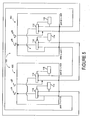
- Figure 7 is block diagram of a three node network.
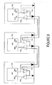
- Figure 8 is a block diagram of data flow through the three node network of figure 7.
- Figure 9 are block diagrams of data flow through a four node network and a four node network with a redundant link after a break in a communication link.
- Connections within a closed loop or a ring network may be made in series or through a daisy chain through an interface adapter.
- the interface adapter may form a closed loop or a ring topology by connecting nodes in series using a communication channel.
- adding a new node to a closed loop or ring topology may be simplified. Instead of breaking the loop or ring to insert a new node, which may bring down the closed loop or ring network, a new node may be added onto the last node of the loop or ring network like a daisy chain without interrupting information flow.
- a new node may be added to the network through a media or channel that links the output port of the last node with the input port of the new node.
- FIG. 1 is a block diagram of an interface adapter 100.
- the interface adapter 100 includes multiple ports in which data may be transferred between an input device and output device.
- two sets of inputs 102 and 104 are connected to a first port 106 and a second port 108, respectively.
- Each set includes an input dedicated to receiving data (e.g., as an input) from a port and an input/output (an I/O) that may send and receive data (e.g., bidirectional flow) from a port.
- I/O input/output
- Interleaving devices or selectors 110 and 112 select an output from a number of inputs or I/Os. Under the control of first and second detecting devices 114 and 116, data flows from the first or second port 106 or 108 to a first network input (e.g., R x ) 118. Data may then be transmitted from a first network output (e.g., T x ) 120 to the first or second port 106 or 108. If data is to flow to the first port 106, the second detecting device 116 selects the I/O and forwards the first network output 120 to the first port 106 through the second interleaving device or selector 112. If data is to flow to the second port 108, data flows from the first network output 120 to the second port 108. By these selections, data may flow in a closed loop or ring even though devices are physically connected in series or a daisy chain.
- the interface adapters 100 of figures 1 - 9 may automatically detect when a device is connected to the first or second port 106 and 108.
- the first and second detecting devices 114 and 116 may detect connections. Some detecting devices may test continuity, some may validate signals or data and others may a apply plug and play logic that allows the network to communicate with an added peripheral without a manual configuration.
- the first and second detecting devices 114 and 116 may detect the relative position of a port to another port and adjust internal data routing to maintain communication flow.
- Figure 2 is a second block diagram of the interface adapter 100.
- data may flow in one or more directions.
- the first network input 118 e.g., R x
- the first network input 118 examines the destination address attached to the message. If the address is the same as the first network input 118, the first network input 118 accepts the message and releases the network. Otherwise, the message is passed to or regenerated and passed to the second port 108 (6) where it is accepted or passed on.
- the message may be returned to the first port 106, which may then be passed on through an alternative path. In this state, the message passes through the second interleaving device or selector 112 to the first port 106 (from 6 to 8) through the control of the second detecting device 116.
- the second detecting device 116 may comprise an automatic signal detector or a signal validation (e.g., a circuit or logic such as software) that selects the message (e.g., the signal received through the I/O).
- Figure 3 illustrates an alternative interface adapter 300 that allows daisy chain architectures to emulate a ring network.
- messages may be passed from one port to another in one direction to form a ring even though nodes and interface adapters 300 may be added in series. Should a failure occur, the interface adapter 300 may bypass a failed or malfunctioning port or node by changing message routing through the interface adapter 300. The adjustment may pass messages in one of two directions that may differ with each interface adapter 300. Under the control of a peripheral device or a controller, messages may be monitored and may be routed to another port to bypass a failure until the data or message reaches its proper destination.
- the interface adapter of figure 3 includes a first and a second physical or logical selector 302 and 304, respectively, that select and funnel one of a number of inputs 102 and 104, respectively, to a common communication link 306 or 308, respectively.
- a first and a second physical or logical selector 302 and 304 are monitored through monitoring lines M 1 and M 2 .
- an input is passed through the first or the second selector 302 or 304.
- the peripheral device or controller sends a signal selection signal through C 1 that passes the valid message to the first network input 118.
- the first network input 118 may examine the destination address attached to the message. The message is then passed or regenerated and passed to the second port 108 through the first network output 120 (e.g., T x ). When a valid message destined for the first port 106 is detected at the second port 108, the peripheral device or controller sends a selection signal through C 2 that passes the valid message to the first port 106 through the second selector 304.
- FIG. 4 is a block diagram of two node daisy chains using the interface adapters 100 of figure 1.
- Each interface adapter 100 includes two sets of ports that connect multiple nodes 400 and 402. Selecting devices 114 and 116 control the flow of messages through the interleaving devices or selectors 110 and 112.
- the first network output 120 transmits a message out of the second port 404.
- Messages received from the second port 404 pass through the first port 406 and the first interleaving device or selector 110 of the second node 402 to the second network input 408 (e.g., R 2x ).
- the second node 402 receives the message, it examines the destination address attached to the message.
- the second node 402 accepts it; otherwise, it passes the message or regenerates and passes the message back to the first node 400.
- a selection signal from the second detecting device 116 of the second node 402 allows the second network output 410 (e.g., T 2x ) to pass through the second interleaving device or selector 112 of the second node 402 to the second port 404 of the first node 400.
- Selection signals from the first and second detecting devices 114 and 116 of the first node 400 allow the second network output 406 or 410 to pass through the first and second interleaving devices or selectors 110 and 112 of the first node 400 into the first network input 118 of the first node 400.
- redundant communication links may be used to bypass malfunctioning nodes, ports, and links.
- the addition of a feedback loop may also be used to reduce propagation delays.
- the addition of the feedback loop allows the interface adapters 100 to route messages between two or more nodes through more than one communication path.
- a redundant communication link may allow the interface adapter to bypass a failed or malfunctioning node without pulling the node out of network.
- the redundant communication link may bypass a failed or malfunctioning node without re-programming the network or interface adapters by changing the direction that a message travels.
- network damage e.g., a broken cable, a damage node
- FIG. 6 is a block diagram of an alternative interface adapter 600 that is a unitary part of devices (nodes) that are to be connected in series but emulate a closed loop, or ring.
- the interface adapter 600 may include intelligence such as logic (e.g., software or firmware) or a processor and a memory such as a buffer.
- the first and second detecting devices 114 and 116 of the interface adapter 600 and those shown in figures 1, 2, and 4-6 may comprise plug and play logic or hardware that senses a node's position in a daisy chain (e.g., first, last, or intermediate; or single port or multiple ports) and adjusts message routing.
- a daisy chain e.g., first, last, or intermediate; or single port or multiple ports
- the first detecting device or logic 114 adjusts its routing such that input to the first node passes through the first interleaving device or selector 110 to the first network input 118.
- the second detecting devices and logic 116 adjust its routing such that the output of the first node passes through the second interleaving device or selector 112 and out through the first port 106.
- Figure 7 is block diagram of a three node daisy chain coupled through alternative interface adapters 700.
- Each node 702, 704, and 706 is coupled to two 2-to-1 multiplexers 708 or 710 that are coupled to presence detect circuits 712, respectively.
- the multiplexers 708 and 710 and presence detect circuits 712 eliminates the need to physically connect the output port of the last node (706 in figure 7) to the input port of the first node (702 in figure 7) in a ring network.
- the presence detect circuits 712 may detect if a node is physically the first node, an intermediate node, or the last node and, based on that detection, activates the multiplexers 708 and 710 to complete the communication ring even when a network is implemented as a daisy chain or series of nodes.
- plug and play circuitry within the presence detect circuit 712 may sense node position (e.g., the first, intermediate, or last node), and accordingly adjust message routing. For instance, if a presence detect circuit 712 senses a one port connection at its second port (e.g., a first node 702 in figure 7), it adjusts its internal routing such that its input comes from the R x pins of the output port of a first connector (714 in figure 7) (e.g., such as an RJ-45 connector).
- node position e.g., the first, intermediate, or last node
- the presence detect circuit 712 senses a one port connection at the first port (e.g., a last node 706 in figure 7) in a daisy chain, it adjusts its internal routing such that its output data are returned upstream through the T x pins of its input port of a last connector (720 in figure 7).
- messages received at the first node 702 pass through the first and second multiplexers 708 and 710 of the first node 702 and into a first node input R x 802. With no devices connected to the first port, messages are transmitted from the first node output T x 804 to the intermediate node 704. Messages received from the first node 702 pass through the first multiplexer 708 of the second node 704 into the second node input R 2x 806. When the second node 704 receives the message, it examines the destination address attached to the message.
- the address is the same as the second node's address it accepts the message and release the network communication link or bus; otherwise, it passes or regenerates the message and passes the message to the third or last node 706.
- Messages transmitted out of the second node output T 2x 808 pass through the first multiplexer 708 of the third node 706 and into a third node input R 3x 810.
- the third node 706 examines the destination address attached to the message.
- the address is the same as the third node's address it accepts the message and releases the network communication link or bus; otherwise, it passes or regenerates the message and passes the message to the first node 702 through the second multiplexer 710 of the third node 706, the second multiplexer 710 of the second node 704 and the first and second multiplexers 708 and 710 of the first node 702..
- Figure 9 illustrates how data may flow in a four node network with or without a redundant communication link after a communication link failure. Since each interface adapter is connected to separate nodes; the ports may communicate with other nodes when failures occur by switching direction of message travel in some or all of the communication paths.
- the interface adapters described above are adaptable to many technologies or devices including devices or structures for transporting people or things such as vehicles, consumer or professional audio platforms, and other technologies and devices that convey data or information from one node to another including local area networks, wide area networks, baseband networks, and broadband networks that may convey electrical or optical data.
- Some circuits and logic may also include one or a combination of filters, termination networks, and adaptive equalizations.
- Some interface adapters match the passive and/or complex impedances that convey the message, data, or signals to the impedance of the input port or an intermediate element.
- the interface adapters may include circuits that pass signals within a certain frequency range or band (e.g., such as about 25 MHz to about 375 MHz) but block or attenuate signals both above and below the band such as a bandpass filter.
- Some interface adapters may include a termination network that matches the impedance of an input and/or equalization that compensates for frequency dependent losses inherent within the communication channel, link, or bus.
- the interface adapter may be embodied in any device that transmit and receive data or messages.
Landscapes
- Engineering & Computer Science (AREA)
- Computer Networks & Wireless Communication (AREA)
- Signal Processing (AREA)
- Small-Scale Networks (AREA)
Abstract
Description
- This application claims the benefit of priority from
U.S. Provisional Application No. 60/760,666, filed January 20, 2006 - The invention relates to networks, and more particularly, to a system that connects two or more devices.
- Networks allow computers to communicate. Networks sometimes establish a cohesive architecture that allows different equipment to transfer information in a near-seamless fashion. There are several ways to physically connect computers including daisy chain and ring topologies.
- A daisy chain connects devices in series. To minimize conflicting communication requests; each device in some daisy chains may be given a different priority, in other daisy chains a device may monitor a communication channel and transmit when an exchange ends. In a ring network devices are connected in a closed loop or a ring. Messages are passed around the ring from one node to the next in one direction. When a node receives a message it examines the destination address attached to the message and accepts it or passes the message to the next node.
- While the continuous passing of messages allow some ring networks to cover large distances, adding new nodes or devices to a ring network may be difficult. To add a new or additional device, that device must be inserted between existing devices that may require a connection to cables and devices that are concealed. A break in the ring will also bring down the entire ring network. Therefore, there is a need for an architecture that simplifies reconfiguring networks. There is also a need for a ring architecture that may bypass a failing node.
- A ring based network comprises a first circuit and a second circuit. The first circuit selects one of a number of inputs and switches an input to a first common communication line. A second circuit selects one of a second number of inputs and switches a second input to a second common communication line linked to one of the first number of inputs. A detect circuit controls the switches of the first and second circuit to emulate a communication ring in which nodes are connected in series in a communication loop.
- Other systems, methods, features, and advantages of the invention will be, or will become, apparent to one with skill in the art upon examination of the following figures and detailed description. It is intended that all such additional systems, methods, features, and advantages be included within this description, be within the scope of the invention, and be protected by the following claims.
- The invention can be better understood with reference to the following drawings and description. The components in the figures are not necessarily to scale, emphasis instead being placed upon illustrating the principles of the invention. Moreover, in the figures, like referenced numerals designate corresponding parts throughout the different views.
- Figure 1 is a block diagram of an interface adapter.
- Figure 2 is a second block diagram of the interface adapter of figure 1.
- Figure 3 is block diagram of an alternative interface adapter.
- Figure 4 is a block diagram of a two node network using the interface adapters of figure 1.
- Figure 5 is a block diagram of multiple interface adapters with a redundant link.
- Figure 6 is a block diagram of an interface adapter integrated with a network interface.
- Figure 7 is block diagram of a three node network.
- Figure 8 is a block diagram of data flow through the three node network of figure 7.
- Figure 9 are block diagrams of data flow through a four node network and a four node network with a redundant link after a break in a communication link.
- Connections within a closed loop or a ring network may be made in series or through a daisy chain through an interface adapter. The interface adapter may form a closed loop or a ring topology by connecting nodes in series using a communication channel. In this system adding a new node to a closed loop or ring topology may be simplified. Instead of breaking the loop or ring to insert a new node, which may bring down the closed loop or ring network, a new node may be added onto the last node of the loop or ring network like a daisy chain without interrupting information flow. In some systems, a new node may be added to the network through a media or channel that links the output port of the last node with the input port of the new node. In these systems there is no need to physically connect the output of the last node of a network to the input of a first node of the network. If a connection completes the ring by connecting the output of the last node to the input of the first node, a redundant path may be created that may minimize the harmful effects of a failed node or a failed communication link.
- Figure 1 is a block diagram of an
interface adapter 100. Theinterface adapter 100 includes multiple ports in which data may be transferred between an input device and output device. In a two port connection, two sets ofinputs first port 106 and asecond port 108, respectively. Each set includes an input dedicated to receiving data (e.g., as an input) from a port and an input/output (an I/O) that may send and receive data (e.g., bidirectional flow) from a port. - Interleaving devices or
selectors devices second port second port first port 106, thesecond detecting device 116 selects the I/O and forwards thefirst network output 120 to thefirst port 106 through the second interleaving device orselector 112. If data is to flow to thesecond port 108, data flows from thefirst network output 120 to thesecond port 108. By these selections, data may flow in a closed loop or ring even though devices are physically connected in series or a daisy chain. - The interface adapters 100 of figures 1 - 9 may automatically detect when a device is connected to the first or
second port devices devices - Figure 2 is a second block diagram of the
interface adapter 100. When coupled to first andsecond ports first port 106 it passes through the first interleaving device orselector 110 to the first network input 118 (e.g., Rx) (from ② to ④). When thefirst network input 118 receives the message, it examines the destination address attached to the message. If the address is the same as thefirst network input 118, thefirst network input 118 accepts the message and releases the network. Otherwise, the message is passed to or regenerated and passed to the second port 108 (⑥) where it is accepted or passed on. If there is a failure at thesecond port 108 or the port is not connected, the message may be returned to thefirst port 106, which may then be passed on through an alternative path. In this state, the message passes through the second interleaving device orselector 112 to the first port 106 (from ⑥ to ⑧) through the control of the second detectingdevice 116. In figure 2, the second detectingdevice 116 may comprise an automatic signal detector or a signal validation (e.g., a circuit or logic such as software) that selects the message (e.g., the signal received through the I/O). - Figure 3 illustrates an
alternative interface adapter 300 that allows daisy chain architectures to emulate a ring network. Through logical connections messages may be passed from one port to another in one direction to form a ring even though nodes andinterface adapters 300 may be added in series. Should a failure occur, theinterface adapter 300 may bypass a failed or malfunctioning port or node by changing message routing through theinterface adapter 300. The adjustment may pass messages in one of two directions that may differ with eachinterface adapter 300. Under the control of a peripheral device or a controller, messages may be monitored and may be routed to another port to bypass a failure until the data or message reaches its proper destination. - The interface adapter of figure 3 includes a first and a second physical or
logical selector inputs common communication link second selector second selector second port 108 is received through thefirst port 106, the peripheral device or controller sends a signal selection signal through C1 that passes the valid message to thefirst network input 118. Thefirst network input 118 may examine the destination address attached to the message. The message is then passed or regenerated and passed to thesecond port 108 through the first network output 120 (e.g., Tx). When a valid message destined for thefirst port 106 is detected at thesecond port 108, the peripheral device or controller sends a selection signal through C2 that passes the valid message to thefirst port 106 through thesecond selector 304. - Figures 4 is a block diagram of two node daisy chains using the
interface adapters 100 of figure 1. Eachinterface adapter 100 includes two sets of ports that connectmultiple nodes devices selectors first node 400 to thesecond node 402 thefirst network output 120 transmits a message out of thesecond port 404. Messages received from thesecond port 404 pass through thefirst port 406 and the first interleaving device orselector 110 of thesecond node 402 to the second network input 408 (e.g., R2x). When thesecond node 402 receives the message, it examines the destination address attached to the message. If the address is the same as the second node's address, thesecond node 402 accepts it; otherwise, it passes the message or regenerates and passes the message back to thefirst node 400. When messages flow from thesecond node 402 to the first node 400 a selection signal from the second detectingdevice 116 of thesecond node 402 allows the second network output 410 (e.g., T2x) to pass through the second interleaving device orselector 112 of thesecond node 402 to thesecond port 404 of thefirst node 400. Selection signals from the first and second detectingdevices first node 400 allow thesecond network output selectors first node 400 into thefirst network input 118 of thefirst node 400. - To minimize network failure, redundant communication links may be used to bypass malfunctioning nodes, ports, and links. The addition of a feedback loop may also be used to reduce propagation delays. In figure 5 the addition of the feedback loop allows the
interface adapters 100 to route messages between two or more nodes through more than one communication path. When the network comprises more than two nodes, a redundant communication link may allow the interface adapter to bypass a failed or malfunctioning node without pulling the node out of network. In some networks, the redundant communication link may bypass a failed or malfunctioning node without re-programming the network or interface adapters by changing the direction that a message travels. In these networks, network damage (e.g., a broken cable, a damage node) may not interrupt information flow. - Figure 6 is a block diagram of an
alternative interface adapter 600 that is a unitary part of devices (nodes) that are to be connected in series but emulate a closed loop, or ring. Theinterface adapter 600 may include intelligence such as logic (e.g., software or firmware) or a processor and a memory such as a buffer. The first and second detectingdevices interface adapter 600 and those shown in figures 1, 2, and 4-6 may comprise plug and play logic or hardware that senses a node's position in a daisy chain (e.g., first, last, or intermediate; or single port or multiple ports) and adjusts message routing. When the detecting devices orlogic logic 114 adjusts its routing such that input to the first node passes through the first interleaving device orselector 110 to thefirst network input 118. When no devices are connected to thesecond port 108, the second detecting devices andlogic 116 adjust its routing such that the output of the first node passes through the second interleaving device orselector 112 and out through thefirst port 106. - Figure 7 is block diagram of a three node daisy chain coupled through
alternative interface adapters 700. Eachnode multiplexers circuits 712, respectively. In some networks themultiplexers circuits 712 eliminates the need to physically connect the output port of the last node (706 in figure 7) to the input port of the first node (702 in figure 7) in a ring network. The presence detectcircuits 712 may detect if a node is physically the first node, an intermediate node, or the last node and, based on that detection, activates themultiplexers - In figure 7 plug and play circuitry within the presence detect
circuit 712 may sense node position (e.g., the first, intermediate, or last node), and accordingly adjust message routing. For instance, if a presence detectcircuit 712 senses a one port connection at its second port (e.g., afirst node 702 in figure 7), it adjusts its internal routing such that its input comes from the Rx pins of the output port of a first connector (714 in figure 7) (e.g., such as an RJ-45 connector). If the presence detectcircuit 712 senses a one port connection at the first port (e.g., alast node 706 in figure 7) in a daisy chain, it adjusts its internal routing such that its output data are returned upstream through the Tx pins of its input port of a last connector (720 in figure 7). - As shown in the three node daisy-chain network of figure 8 (presence detect
circuits 712 not shown), messages received at thefirst node 702 pass through the first andsecond multiplexers first node 702 and into a firstnode input R x 802. With no devices connected to the first port, messages are transmitted from the firstnode output T x 804 to theintermediate node 704. Messages received from thefirst node 702 pass through thefirst multiplexer 708 of thesecond node 704 into the secondnode input R 2x 806. When thesecond node 704 receives the message, it examines the destination address attached to the message. If the address is the same as the second node's address it accepts the message and release the network communication link or bus; otherwise, it passes or regenerates the message and passes the message to the third orlast node 706. Messages transmitted out of the secondnode output T 2x 808 pass through thefirst multiplexer 708 of thethird node 706 and into a thirdnode input R 3x 810. When thethird node 706 receives the message, it examines the destination address attached to the message. If the address is the same as the third node's address it accepts the message and releases the network communication link or bus; otherwise, it passes or regenerates the message and passes the message to thefirst node 702 through thesecond multiplexer 710 of thethird node 706, thesecond multiplexer 710 of thesecond node 704 and the first andsecond multiplexers first node 702.. - Figure 9 illustrates how data may flow in a four node network with or without a redundant communication link after a communication link failure. Since each interface adapter is connected to separate nodes; the ports may communicate with other nodes when failures occur by switching direction of message travel in some or all of the communication paths.
- The interface adapters described above are adaptable to many technologies or devices including devices or structures for transporting people or things such as vehicles, consumer or professional audio platforms, and other technologies and devices that convey data or information from one node to another including local area networks, wide area networks, baseband networks, and broadband networks that may convey electrical or optical data. Some circuits and logic may also include one or a combination of filters, termination networks, and adaptive equalizations. Some interface adapters match the passive and/or complex impedances that convey the message, data, or signals to the impedance of the input port or an intermediate element. The interface adapters may include circuits that pass signals within a certain frequency range or band (e.g., such as about 25 MHz to about 375 MHz) but block or attenuate signals both above and below the band such as a bandpass filter. Some interface adapters may include a termination network that matches the impedance of an input and/or equalization that compensates for frequency dependent losses inherent within the communication channel, link, or bus. The interface adapter may be embodied in any device that transmit and receive data or messages.
- While various embodiments of the invention have been described, it will be apparent to those of ordinary skill in the art that many more embodiments and implementations are possible within the scope of the invention. Accordingly, the invention is not to be restricted except in light of the attached claims and their equivalents.
Claims (20)
- A ring based network comprising;a first circuit that selects one of a first number of inputs and switches a first input to a first common communication line;a second circuit that selects one of a second number of inputs and switches a second input to a second common communication line coupled to one of the first number of inputs; anda detect circuit that controls the switches to emulate a communication ring in which nodes are connected in series in a communication loop.
- The ring based network of claim 1 where the detect circuit comprises plug and play logic.
- The ring based network of claim 1 where the first circuit and the second circuit are configured to transmit a message with a destination address.
- The ring based network of claim 1 where the detect circuit comprises a first detect device and a second detect device, where the second detect device is coupled to an input of a first node and an output of a second node.
- The ring based network of claim 4 where the first detect device is coupled to an output of a third node and an input of the second node.
- The ring based network of claim 1 where the nodes are coupled in series and the closed loop is simulated by the switching of the first circuit and the second circuit.
- The ring network of claim 1 where the first circuit comprises a first interleaving device and the second circuit comprises a second interleaving device.
- The ring network of claim 1 where the detect circuit is configured to monitor a communication link and bypass a failed node.
- The ring network of claim 1 where the detect circuit comprises a unitary part of the second circuit.
- The ring network of claim 1 where the detect circuit is configured to monitor continuity through a portion of the communication loop.
- A ring network, comprising:a first node coupled to a first interface adapter;a second node coupled to a second interface adapter; andwhere the first node and interface adapter couples the second node and interface adapter in series but emulates a ring network.
- The ring network of claim 11 where the ring network comprises a local area network.
- The ring network of claim 11 where the first node is coupled to a vehicle.
- The ring network of claim 11 where the first interface adapter comprises a first interleaving device that selects one of a first number of inputs and switches a first input to a first common communication line.
- The ring network of claim 14 where the second interface adapter comprises a second interleaving device that selects one of a second number of inputs and switches a second input to a second common communication line coupled to one of the first number of inputs.
- The ring network of claim 14 where comprising a first presence detect circuit coupled to the first interleaving device.
- The ring network of claim 15 further comprising a second presence detect circuit coupled to the second interleaving device.
- The network of claim 14 where the interface adapters are configured to bypass a failing node.
- The network of claim 14 further comprising a first filter coupled to an input of the first interface adapter and a second filter coupled to an of the second interface adapter.
- The network of claim 19 further comprising a first adaptive equalization device coupled to an input of the first interface adapter and a second adaptive equalization device coupled to an of the second interface adapter.
Applications Claiming Priority (2)
| Application Number | Priority Date | Filing Date | Title |
|---|---|---|---|
| US76066606P | 2006-01-20 | 2006-01-20 | |
| US11/385,635 US7898988B2 (en) | 2006-01-20 | 2006-03-21 | Self annealing auto-expanding network |
Publications (2)
| Publication Number | Publication Date |
|---|---|
| EP1811723A1 true EP1811723A1 (en) | 2007-07-25 |
| EP1811723B1 EP1811723B1 (en) | 2014-11-05 |
Family
ID=38285508
Family Applications (1)
| Application Number | Title | Priority Date | Filing Date |
|---|---|---|---|
| EP07000907.1A Active EP1811723B1 (en) | 2006-01-20 | 2007-01-17 | Self annealing auto-expanding network |
Country Status (3)
| Country | Link |
|---|---|
| US (1) | US7898988B2 (en) |
| EP (1) | EP1811723B1 (en) |
| JP (2) | JP4422157B2 (en) |
Cited By (2)
| Publication number | Priority date | Publication date | Assignee | Title |
|---|---|---|---|---|
| CN106656715A (en) * | 2016-11-11 | 2017-05-10 | 安徽维德工业自动化有限公司 | Industrial Ethernet switch redundancy loop technology |
| CN111125849A (en) * | 2019-11-30 | 2020-05-08 | 浙江华云信息科技有限公司 | Ring-breaking processing method for tree-like structure graph model |
Families Citing this family (52)
| Publication number | Priority date | Publication date | Assignee | Title |
|---|---|---|---|---|
| US8289965B2 (en) | 2006-10-19 | 2012-10-16 | Embarq Holdings Company, Llc | System and method for establishing a communications session with an end-user based on the state of a network connection |
| US8194643B2 (en) | 2006-10-19 | 2012-06-05 | Embarq Holdings Company, Llc | System and method for monitoring the connection of an end-user to a remote network |
| US8717911B2 (en) | 2006-06-30 | 2014-05-06 | Centurylink Intellectual Property Llc | System and method for collecting network performance information |
| US9094257B2 (en) | 2006-06-30 | 2015-07-28 | Centurylink Intellectual Property Llc | System and method for selecting a content delivery network |
| US7948909B2 (en) | 2006-06-30 | 2011-05-24 | Embarq Holdings Company, Llc | System and method for resetting counters counting network performance information at network communications devices on a packet network |
| US8477614B2 (en) | 2006-06-30 | 2013-07-02 | Centurylink Intellectual Property Llc | System and method for routing calls if potential call paths are impaired or congested |
| US8488447B2 (en) | 2006-06-30 | 2013-07-16 | Centurylink Intellectual Property Llc | System and method for adjusting code speed in a transmission path during call set-up due to reduced transmission performance |
| US8000318B2 (en) | 2006-06-30 | 2011-08-16 | Embarq Holdings Company, Llc | System and method for call routing based on transmission performance of a packet network |
| JP4816323B2 (en) * | 2006-08-16 | 2011-11-16 | ソニー株式会社 | COMMUNICATION DEVICE, COMMUNICATION METHOD, AND PROGRAM |
| US8130793B2 (en) | 2006-08-22 | 2012-03-06 | Embarq Holdings Company, Llc | System and method for enabling reciprocal billing for different types of communications over a packet network |
| US8531954B2 (en) | 2006-08-22 | 2013-09-10 | Centurylink Intellectual Property Llc | System and method for handling reservation requests with a connection admission control engine |
| US8274905B2 (en) | 2006-08-22 | 2012-09-25 | Embarq Holdings Company, Llc | System and method for displaying a graph representative of network performance over a time period |
| US8743703B2 (en) | 2006-08-22 | 2014-06-03 | Centurylink Intellectual Property Llc | System and method for tracking application resource usage |
| US8189468B2 (en) | 2006-10-25 | 2012-05-29 | Embarq Holdings, Company, LLC | System and method for regulating messages between networks |
| US7684332B2 (en) | 2006-08-22 | 2010-03-23 | Embarq Holdings Company, Llc | System and method for adjusting the window size of a TCP packet through network elements |
| US8144586B2 (en) | 2006-08-22 | 2012-03-27 | Embarq Holdings Company, Llc | System and method for controlling network bandwidth with a connection admission control engine |
| US8224255B2 (en) | 2006-08-22 | 2012-07-17 | Embarq Holdings Company, Llc | System and method for managing radio frequency windows |
| US7843831B2 (en) | 2006-08-22 | 2010-11-30 | Embarq Holdings Company Llc | System and method for routing data on a packet network |
| US8549405B2 (en) | 2006-08-22 | 2013-10-01 | Centurylink Intellectual Property Llc | System and method for displaying a graphical representation of a network to identify nodes and node segments on the network that are not operating normally |
| US8576722B2 (en) | 2006-08-22 | 2013-11-05 | Centurylink Intellectual Property Llc | System and method for modifying connectivity fault management packets |
| US9479341B2 (en) | 2006-08-22 | 2016-10-25 | Centurylink Intellectual Property Llc | System and method for initiating diagnostics on a packet network node |
| US7889660B2 (en) * | 2006-08-22 | 2011-02-15 | Embarq Holdings Company, Llc | System and method for synchronizing counters on an asynchronous packet communications network |
| US8223654B2 (en) | 2006-08-22 | 2012-07-17 | Embarq Holdings Company, Llc | Application-specific integrated circuit for monitoring and optimizing interlayer network performance |
| US8307065B2 (en) | 2006-08-22 | 2012-11-06 | Centurylink Intellectual Property Llc | System and method for remotely controlling network operators |
| US8144587B2 (en) * | 2006-08-22 | 2012-03-27 | Embarq Holdings Company, Llc | System and method for load balancing network resources using a connection admission control engine |
| US8107366B2 (en) | 2006-08-22 | 2012-01-31 | Embarq Holdings Company, LP | System and method for using centralized network performance tables to manage network communications |
| US7940735B2 (en) | 2006-08-22 | 2011-05-10 | Embarq Holdings Company, Llc | System and method for selecting an access point |
| US8015294B2 (en) | 2006-08-22 | 2011-09-06 | Embarq Holdings Company, LP | Pin-hole firewall for communicating data packets on a packet network |
| US8040811B2 (en) | 2006-08-22 | 2011-10-18 | Embarq Holdings Company, Llc | System and method for collecting and managing network performance information |
| US8228791B2 (en) | 2006-08-22 | 2012-07-24 | Embarq Holdings Company, Llc | System and method for routing communications between packet networks based on intercarrier agreements |
| US8619600B2 (en) | 2006-08-22 | 2013-12-31 | Centurylink Intellectual Property Llc | System and method for establishing calls over a call path having best path metrics |
| US8064391B2 (en) | 2006-08-22 | 2011-11-22 | Embarq Holdings Company, Llc | System and method for monitoring and optimizing network performance to a wireless device |
| US8223655B2 (en) | 2006-08-22 | 2012-07-17 | Embarq Holdings Company, Llc | System and method for provisioning resources of a packet network based on collected network performance information |
| US8125897B2 (en) | 2006-08-22 | 2012-02-28 | Embarq Holdings Company Lp | System and method for monitoring and optimizing network performance with user datagram protocol network performance information packets |
| US8537695B2 (en) | 2006-08-22 | 2013-09-17 | Centurylink Intellectual Property Llc | System and method for establishing a call being received by a trunk on a packet network |
| US8098579B2 (en) | 2006-08-22 | 2012-01-17 | Embarq Holdings Company, LP | System and method for adjusting the window size of a TCP packet through remote network elements |
| US8238253B2 (en) | 2006-08-22 | 2012-08-07 | Embarq Holdings Company, Llc | System and method for monitoring interlayer devices and optimizing network performance |
| US8750158B2 (en) | 2006-08-22 | 2014-06-10 | Centurylink Intellectual Property Llc | System and method for differentiated billing |
| US8199653B2 (en) | 2006-08-22 | 2012-06-12 | Embarq Holdings Company, Llc | System and method for communicating network performance information over a packet network |
| US8194555B2 (en) | 2006-08-22 | 2012-06-05 | Embarq Holdings Company, Llc | System and method for using distributed network performance information tables to manage network communications |
| US7808918B2 (en) | 2006-08-22 | 2010-10-05 | Embarq Holdings Company, Llc | System and method for dynamically shaping network traffic |
| US8407765B2 (en) | 2006-08-22 | 2013-03-26 | Centurylink Intellectual Property Llc | System and method for restricting access to network performance information tables |
| FR2913155B1 (en) * | 2007-02-26 | 2009-04-24 | Sagem Defense Securite | SELECTIVE CONNECTION DEVICE FOR CONNECTING AT LEAST ONE DEVICE TO A TARGET COMPUTER AND A SELECTIVE CONTROL SYSTEM COMPRISING SUCH A DEVICE |
| US8111692B2 (en) | 2007-05-31 | 2012-02-07 | Embarq Holdings Company Llc | System and method for modifying network traffic |
| US8068425B2 (en) | 2008-04-09 | 2011-11-29 | Embarq Holdings Company, Llc | System and method for using network performance information to determine improved measures of path states |
| US8271697B2 (en) | 2009-09-29 | 2012-09-18 | Micron Technology, Inc. | State change in systems having devices coupled in a chained configuration |
| JP5672927B2 (en) * | 2010-10-08 | 2015-02-18 | セイコーエプソン株式会社 | Storage device, host device, circuit board, liquid container and system |
| US9065810B2 (en) | 2013-01-30 | 2015-06-23 | Ebay Inc. | Daisy chain distribution in data centers |
| EP3427208A1 (en) | 2016-06-30 | 2019-01-16 | Copper LLC | Smart data cable for point of sale systems |
| US11436181B2 (en) | 2016-06-30 | 2022-09-06 | Copper Inc. | Data processing systems and methods for transmitting and modifying data via a smart data cable |
| US11321693B1 (en) | 2020-12-10 | 2022-05-03 | Copper Inc. | Data processing systems and methods for transmitting and modifying data via a smart data cable |
| US11321261B1 (en) * | 2020-12-10 | 2022-05-03 | Copper Inc. | Data processing systems and methods for transmitting and modifying data via a smart data cable |
Citations (1)
| Publication number | Priority date | Publication date | Assignee | Title |
|---|---|---|---|---|
| GB2152789A (en) * | 1984-01-09 | 1985-08-07 | Fiberlan Inc | Time division multiplex ring |
Family Cites Families (7)
| Publication number | Priority date | Publication date | Assignee | Title |
|---|---|---|---|---|
| JP2663687B2 (en) * | 1990-07-27 | 1997-10-15 | 日本電気株式会社 | ATM communication system in dual ring network |
| US5694547A (en) * | 1992-10-13 | 1997-12-02 | Bay Networks, Inc. | System for registration of clients in an ATM network providing for communication of client registration messages to a central manager |
| US6262993B1 (en) * | 1996-11-08 | 2001-07-17 | Kevin Kirmse | Computer and peripheral networking device permitting the practical use of buffer insertion-based networks while communicating over unshielded twisted pair conductive media |
| DE19715262A1 (en) * | 1997-04-12 | 1998-10-15 | Philips Patentverwaltung | Local network for reconfiguration in the event of line breaks or node failure |
| US6922390B1 (en) * | 1999-06-15 | 2005-07-26 | Nortel Networks Limited | Method and apparatus for forecasting and controlling congestion in a data transport network |
| JP2002185490A (en) * | 2000-12-19 | 2002-06-28 | Denso Corp | Communication system and terminal device |
| US7151742B1 (en) * | 2002-03-08 | 2006-12-19 | Mindspeed Technologies, Inc. | Flow control for communication ring access control |
-
2006
- 2006-03-21 US US11/385,635 patent/US7898988B2/en active Active
-
2007
- 2007-01-17 JP JP2007007796A patent/JP4422157B2/en active Active
- 2007-01-17 EP EP07000907.1A patent/EP1811723B1/en active Active
-
2009
- 2009-08-18 JP JP2009189595A patent/JP4846005B2/en active Active
Patent Citations (1)
| Publication number | Priority date | Publication date | Assignee | Title |
|---|---|---|---|---|
| GB2152789A (en) * | 1984-01-09 | 1985-08-07 | Fiberlan Inc | Time division multiplex ring |
Cited By (2)
| Publication number | Priority date | Publication date | Assignee | Title |
|---|---|---|---|---|
| CN106656715A (en) * | 2016-11-11 | 2017-05-10 | 安徽维德工业自动化有限公司 | Industrial Ethernet switch redundancy loop technology |
| CN111125849A (en) * | 2019-11-30 | 2020-05-08 | 浙江华云信息科技有限公司 | Ring-breaking processing method for tree-like structure graph model |
Also Published As
| Publication number | Publication date |
|---|---|
| JP2009273158A (en) | 2009-11-19 |
| JP4846005B2 (en) | 2011-12-28 |
| JP2007195183A (en) | 2007-08-02 |
| US20070171937A1 (en) | 2007-07-26 |
| JP4422157B2 (en) | 2010-02-24 |
| US7898988B2 (en) | 2011-03-01 |
| EP1811723B1 (en) | 2014-11-05 |
Similar Documents
| Publication | Publication Date | Title |
|---|---|---|
| US7898988B2 (en) | Self annealing auto-expanding network | |
| US5247381A (en) | Apparatus and method for automatically reconfiguring, free space local area network systems | |
| US20050129033A1 (en) | Network tap for use with multiple attached devices | |
| US6052210A (en) | System and method for increasing the robustness of an optical ring network | |
| US5387902A (en) | Data networks | |
| JP2010510741A (en) | Communication system having master / slave structure | |
| CN111669255A (en) | Loopback test method, device, circuit, equipment and medium for communication equipment network port | |
| US20040215832A1 (en) | Network tap with interchangeable ports | |
| JP3574425B2 (en) | Packet Processing Method Using Multi-Fault-Tolerant Network Structure | |
| US5189541A (en) | Method and apparatus for connecting branch networks with a trunk network in optical transmission system | |
| US6414953B1 (en) | Multi-protocol cross connect switch | |
| US20110095767A1 (en) | Ethernet test-set cable | |
| US5317569A (en) | Alternate path FDDI standard LAN | |
| KR102101066B1 (en) | Fault-tolerant power network | |
| JPH03208419A (en) | Switching control system for protection line | |
| US5420986A (en) | FDDI concentrator with backplane port for dual datapath systems | |
| CN108292998B (en) | Bus coupling unit and bus system with bus coupling unit | |
| US7944157B2 (en) | Dual ring dedicated drive control system for medium voltage variable frequency drives | |
| US20050060394A1 (en) | Programmable delay, transparent switching multi-port interface line card | |
| CN112422175A (en) | Cascade device | |
| US6452965B1 (en) | Fault detection circuit in loop network | |
| CN120185701A (en) | A kind of integrated flow distribution processing system with LAN port | |
| WO1992013402A1 (en) | Apparatus and method for automatically reconfiguring free space local area network systems | |
| CN120185700A (en) | A light protection system | |
| JPS6394727A (en) | Hikari local area network |
Legal Events
| Date | Code | Title | Description |
|---|---|---|---|
| PUAI | Public reference made under article 153(3) epc to a published international application that has entered the european phase |
Free format text: ORIGINAL CODE: 0009012 |
|
| 17P | Request for examination filed |
Effective date: 20070117 |
|
| AK | Designated contracting states |
Kind code of ref document: A1 Designated state(s): AT BE BG CH CY CZ DE DK EE ES FI FR GB GR HU IE IS IT LI LT LU LV MC NL PL PT RO SE SI SK TR |
|
| AX | Request for extension of the european patent |
Extension state: AL BA HR MK YU |
|
| AKX | Designation fees paid |
Designated state(s): DE FR GB IT |
|
| 17Q | First examination report despatched |
Effective date: 20081022 |
|
| GRAP | Despatch of communication of intention to grant a patent |
Free format text: ORIGINAL CODE: EPIDOSNIGR1 |
|
| INTG | Intention to grant announced |
Effective date: 20140513 |
|
| GRAS | Grant fee paid |
Free format text: ORIGINAL CODE: EPIDOSNIGR3 |
|
| GRAA | (expected) grant |
Free format text: ORIGINAL CODE: 0009210 |
|
| AK | Designated contracting states |
Kind code of ref document: B1 Designated state(s): DE FR GB IT |
|
| REG | Reference to a national code |
Ref country code: GB Ref legal event code: FG4D |
|
| REG | Reference to a national code |
Ref country code: DE Ref legal event code: R096 Ref document number: 602007039097 Country of ref document: DE Effective date: 20141218 |
|
| REG | Reference to a national code |
Ref country code: DE Ref legal event code: R097 Ref document number: 602007039097 Country of ref document: DE |
|
| PLBE | No opposition filed within time limit |
Free format text: ORIGINAL CODE: 0009261 |
|
| STAA | Information on the status of an ep patent application or granted ep patent |
Free format text: STATUS: NO OPPOSITION FILED WITHIN TIME LIMIT |
|
| 26N | No opposition filed |
Effective date: 20150806 |
|
| REG | Reference to a national code |
Ref country code: FR Ref legal event code: ST Effective date: 20150930 |
|
| PG25 | Lapsed in a contracting state [announced via postgrant information from national office to epo] |
Ref country code: FR Free format text: LAPSE BECAUSE OF NON-PAYMENT OF DUE FEES Effective date: 20150202 |
|
| PG25 | Lapsed in a contracting state [announced via postgrant information from national office to epo] |
Ref country code: IT Free format text: LAPSE BECAUSE OF FAILURE TO SUBMIT A TRANSLATION OF THE DESCRIPTION OR TO PAY THE FEE WITHIN THE PRESCRIBED TIME-LIMIT Effective date: 20141105 |
|
| REG | Reference to a national code |
Ref country code: DE Ref legal event code: R082 Ref document number: 602007039097 Country of ref document: DE Representative=s name: MAUCHER JENKINS PATENTANWAELTE & RECHTSANWAELT, DE |
|
| P01 | Opt-out of the competence of the unified patent court (upc) registered |
Effective date: 20230527 |
|
| PGFP | Annual fee paid to national office [announced via postgrant information from national office to epo] |
Ref country code: GB Payment date: 20251220 Year of fee payment: 20 |
|
| PGFP | Annual fee paid to national office [announced via postgrant information from national office to epo] |
Ref country code: DE Payment date: 20251217 Year of fee payment: 20 |