EP1811354A1 - Plant monitoring apparatus and plant monitoring method - Google Patents
Plant monitoring apparatus and plant monitoring method Download PDFInfo
- Publication number
- EP1811354A1 EP1811354A1 EP07000769A EP07000769A EP1811354A1 EP 1811354 A1 EP1811354 A1 EP 1811354A1 EP 07000769 A EP07000769 A EP 07000769A EP 07000769 A EP07000769 A EP 07000769A EP 1811354 A1 EP1811354 A1 EP 1811354A1
- Authority
- EP
- European Patent Office
- Prior art keywords
- warning
- warnings
- data
- criteria
- unit
- Prior art date
- Legal status (The legal status is an assumption and is not a legal conclusion. Google has not performed a legal analysis and makes no representation as to the accuracy of the status listed.)
- Granted
Links
Images



Classifications
-
- G—PHYSICS
- G05—CONTROLLING; REGULATING
- G05B—CONTROL OR REGULATING SYSTEMS IN GENERAL; FUNCTIONAL ELEMENTS OF SUCH SYSTEMS; MONITORING OR TESTING ARRANGEMENTS FOR SUCH SYSTEMS OR ELEMENTS
- G05B19/00—Program-control systems
- G05B19/02—Program-control systems electric
- G05B19/18—Numerical control [NC], i.e. automatically operating machines, in particular machine tools, e.g. in a manufacturing environment, so as to execute positioning, movement or co-ordinated operations by means of program data in numerical form
- G05B19/409—Numerical control [NC], i.e. automatically operating machines, in particular machine tools, e.g. in a manufacturing environment, so as to execute positioning, movement or co-ordinated operations by means of program data in numerical form characterised by using manual data input [MDI] or by using control panel, e.g. controlling functions with the panel; characterised by control panel details or by setting parameters
-
- G—PHYSICS
- G05—CONTROLLING; REGULATING
- G05B—CONTROL OR REGULATING SYSTEMS IN GENERAL; FUNCTIONAL ELEMENTS OF SUCH SYSTEMS; MONITORING OR TESTING ARRANGEMENTS FOR SUCH SYSTEMS OR ELEMENTS
- G05B23/00—Testing or monitoring of control systems or parts thereof
- G05B23/02—Electric testing or monitoring
- G05B23/0205—Electric testing or monitoring by means of a monitoring system capable of detecting and responding to faults
- G05B23/0259—Electric testing or monitoring by means of a monitoring system capable of detecting and responding to faults characterized by the response to fault detection
- G05B23/0267—Fault communication, e.g. human machine interface [HMI]
- G05B23/0272—Presentation of monitored results, e.g. selection of status reports to be displayed; Filtering information to the user
-
- G—PHYSICS
- G05—CONTROLLING; REGULATING
- G05B—CONTROL OR REGULATING SYSTEMS IN GENERAL; FUNCTIONAL ELEMENTS OF SUCH SYSTEMS; MONITORING OR TESTING ARRANGEMENTS FOR SUCH SYSTEMS OR ELEMENTS
- G05B2219/00—Program-control systems
- G05B2219/30—Nc systems
- G05B2219/31—From computer integrated manufacturing till monitoring
- G05B2219/31438—Priority, queue of alarms
-
- G—PHYSICS
- G05—CONTROLLING; REGULATING
- G05B—CONTROL OR REGULATING SYSTEMS IN GENERAL; FUNCTIONAL ELEMENTS OF SUCH SYSTEMS; MONITORING OR TESTING ARRANGEMENTS FOR SUCH SYSTEMS OR ELEMENTS
- G05B2219/00—Program-control systems
- G05B2219/30—Nc systems
- G05B2219/31—From computer integrated manufacturing till monitoring
- G05B2219/31439—Alarms can be warning, alert or fault
-
- G—PHYSICS
- G05—CONTROLLING; REGULATING
- G05B—CONTROL OR REGULATING SYSTEMS IN GENERAL; FUNCTIONAL ELEMENTS OF SUCH SYSTEMS; MONITORING OR TESTING ARRANGEMENTS FOR SUCH SYSTEMS OR ELEMENTS
- G05B2219/00—Program-control systems
- G05B2219/30—Nc systems
- G05B2219/31—From computer integrated manufacturing till monitoring
- G05B2219/31469—Graphical display of process as function of detected alarm signals
Definitions
- the present invention relates to a plant monitoring apparatus and a plant monitoring method particularly for classifying warnings into each category and displaying the classified warnings.
- a plant monitoring apparatus has a function for issuing warnings in a monitoring operation.
- This warning function provides a mechanism for determining whether warnings are to be issued when a plant monitoring apparatus enters a predetermined state during the operation of a plant, and under the determination, the warnings are notified to operators or so.
- a known plant monitoring apparatus 11 includes a power generation plant 12, a process measuring unit 13, a warning determining unit 14, a display processing unit 16, and a display unit 17.
- the process measuring unit 13 measures variables indicating states of the power generation plant 12 to obtain process data.
- the warning determining unit 14 determines whether a warning is to be issued on the basis of the process data and a predetermined criterion.
- the display processing unit 16 processes warning data into a displayable form, and supplies the data to the display unit 17.
- the plant monitoring apparatus determines whether the warning is to be issued or not according to changes of state.
- One of such plant monitoring apparatuses manages information supplied from sensors in an integrated fashion and sets a warning level after determining whether or not the information supplied from the sensors is normal when an error occurs (See Japanese Unexamined Patent Application Publication No. 2002-117468 ).
- the present invention was conceived in consideration of circumstances encountered in the prior art mentioned above, and it is an object of the present invention to provide a plant monitoring apparatus and a plant monitoring method capable of efficiently notifying an operator of a plurality of critical warnings among many warnings.
- a plant monitoring apparatus comprising:
- the classified warnings are displayed on different screens for each classification criterion.
- the different screens may be hierarchical screens.
- the display/setting unit writes data in the warning criteria database through the warning criteria setting unit, and a screen displayed thereon allows specification of selected ranges of the warnings displayed according to one or more classification criteria.
- the selected ranges include a range written in the warning criteria database through the warning criteria setting unit and a range predetermined according to the classification criteria.
- the screen allowing the specification of the selected ranges of the warnings shows the number of warnings to be displayed when a currently specified range is selected.
- the selected ranges of the warnings may be displayed on a screen.
- a plant monitoring method comprising the steps of:
- a plant monitoring device capable of efficiently notifying operators or the like of a plurality of critical warnings among many warnings can be provided.
- a plant monitoring apparatus 1 includes a power generation plant 2, a process measuring unit 3, a warning determining unit 4, a warning selecting unit 5, a display processing unit 6, a display/ setting unit 7, a warning criteria supplying unit 8, a warning criteria database 9, and a warning criteria setting unit 10.
- functions of the process measuring unit 3, the warning determining unit 4, the warning selecting unit 5, the display processing unit 6, the display/setting unit 7, the warning criteria supplying unit 8, the warning criteria database 9, and the warning criteria setting unit 10 are implemented by programs causing a computer to operate.
- the process measuring unit 3 periodically collects process values at each input point of the power generation plant 2, and stores the process values in a plant data storage unit 3a.
- the warning determining unit 4 loads the plant data stored in the plant data storage unit 3a and determines whether warning or warnings are to be issued on the basis of a predetermined criterion.
- the warning selecting unit 5 adds selection data, which is described below, loaded from the warning criteria supplying unit 8 to the warning data supplied from the warning determining unit 4.
- the warning selecting unit 5 also compares the warning data with one or more classification criteria supplied from the warning criteria supplying unit 8 so as to classify the warnings into a plurality of categories.
- the display/setting unit 7 loads the warning data, attached with the selection data by the warning selecting unit 5, through the display processing unit 6 and displays plant monitoring information to operators. In addition, in response to an interaction request from the operators, the display/setting unit 7 receives information on system screens and on monitoring range specification.
- the warning criteria database 9 is accessed by the display/ setting unit 7 through the warning criteria setting unit 10.
- the warning criteria supplying unit 8 loads warning criteria from the warning criteria database 9.
- the plant measuring unit 3 periodically collects the process values at each input point of the power generation plant 2 and stores the process values in the plant data storage unit 3a (step S1).
- the warning determining unit 4 loads the plant data stored in the plant data storage unit 3a and compares the plant data with a warning issuance criterion so as to determine whether or not issuance of warnings is necessary (step S2).
- the warning determining unit 4 selects only data indicating the necessity of the issuance of the warnings from the loaded plant data so as to reduce the amount of warning data.
- the warning determining unit 4 supplies the data determined to indicate the necessity of the issuance of the warnings to the warning selecting unit 5 as the warning data (step S3).
- the warning selecting unit 5 loads the selection data from the warning criteria database 9 through the warning criteria supplying unit 8.
- the warning selecting unit 5 attaches the selection data to the warning data supplied from the warning determining unit 4 (step S4).
- Fig. 4A shows processing performed on data supplied to the display/setting unit 7 through the display processing unit 6, whereas Fig. 4B shows an example of a screen configuration.
- the selection data attached by the warning selecting unit 5 may indicate, for example, warning severity levels, such as “high”, “intermediate”, and “low”.
- warning severity levels such as “high”, “intermediate”, and "low”.
- a vertical direction of a cone shows the warning severity levels, such as “high”, “intermediate”, and “low”.
- a section of the cone in the horizontal direction conceptually shows the number of issued warnings. This example shows a circumstance where the number of "high” level warnings is few, whereas the number of warnings increases as the severity level goes down to "intermediate” and "low”.
- the warning data attached with the selection data by the warning selecting unit 5 is provided to the display/setting unit 7 through the display processing unit 6.
- the warnings corresponding to the warning data are classified into each category according to the categories of the selection data and are displayed on the display/setting unit 7 (step S5).
- the classified warnings may be shown in different screens displayed on the display/setting unit 7 according to the classification criteria. For example, three hierarchical screens are displayed simultaneously and superimposed on top of each other using tags. These three screens correspond to the warning severity levels, e.g., "high”, “intermediate” and "low".
- the warnings having the selection data classified into the "high” severity level are displayed on a "high” level screen.
- Warnings having the selection data classified into the "high” and “intermediate” severity levels are displayed on a “intermediate” level screen.
- the warnings having the selection data classified into the "high”, “intermediate”, and “low” severity levels are displayed on a “low” level screen. That is, all the warnings are displayed on the "low” level screen. Accordingly, the warnings are displayed with the number of warnings decreasing as the severity level increases.
- the "high” level screen shows an extremely small number of warnings, which can prevent operators from missing the critical warnings and can ensure safety.
- the "low” level screen shows all the warnings, which allows operators to recognize the operational state of the plant through the number of warnings.
- step S6 a step of generating the selection data (step S6) used at step S4 will be described.
- Fig. 5 shows a screen example displayed on the display/setting unit 7, in which the warning criteria data is set in the warning criteria database 9 through the warning criteria setting unit 10 using the screen example.
- each warning is rated for two factors, that is, the first one is the severity level and the second one is a signal level.
- the severity level i.e., the first factor
- the severity level of a warning about an error in a printer connected to a plant monitoring apparatus is set at 0.2
- the severity level of a warning about boiler temperature is set at 0.8.
- the error in the printer connected to the plant monitoring apparatus does not have to be fixed until the printer is used.
- the high temperature in the boiler may cause a failure in an operation of the plant if the warning thereof is ignored. Since the warning about the high temperature in the boiler is more critical than the error in the printer, a higher value is granted to the warning about the high temperature in the boiler.
- the signal level i.e., the second factor
- the signal level indicates a level regarding process quantities of each process element to be monitored.
- the severity level i.e., the first factor
- the signal level i.e., the second factor
- ranges allow operators to specify a range corresponding to the warning severity level, such as "high” or “intermediate”. In this case, the rest of the ranges correspond to a range of the "low” warning severity level.
- the plant monitoring apparatus may be configured to specify an area (e.g., the upper right area shown in Fig. 5) where both the signal level and the severity level are highest as a range corresponding to the "high” severity level. At this time, a method allowing operators to interactively set the warning ranges using a mouse may be used.
- each area may have a function for displaying the number of warnings currently issued. This allows operators to specify the total number of warnings to be displayed for confirmation. Additionally, at this time, it is preferable to display the warnings located at the "high" level range determined by the specification. Furthermore, preferably, the plant monitoring apparatus may have a function for displaying a screen showing current settings in order to allow operators to confirm the current warning display ranges when other operators take over from the current operators.
- an embodiment of the present invention implements a plant monitoring apparatus capable of efficiently notifying operators or the like of a plurality of critical warnings among many warnings by providing a warning selecting unit between a warning determining unit and a display processing unit.
Landscapes
- Engineering & Computer Science (AREA)
- Human Computer Interaction (AREA)
- Physics & Mathematics (AREA)
- General Physics & Mathematics (AREA)
- Automation & Control Theory (AREA)
- Manufacturing & Machinery (AREA)
- Testing And Monitoring For Control Systems (AREA)
- Alarm Systems (AREA)
Abstract
Description
- The present invention relates to a plant monitoring apparatus and a plant monitoring method particularly for classifying warnings into each category and displaying the classified warnings.
- Generally, a plant monitoring apparatus has a function for issuing warnings in a monitoring operation. This warning function provides a mechanism for determining whether warnings are to be issued when a plant monitoring apparatus enters a predetermined state during the operation of a plant, and under the determination, the warnings are notified to operators or so.
- As shown in Fig. 6, a known plant monitoring apparatus 11 includes a
power generation plant 12, aprocess measuring unit 13, awarning determining unit 14, adisplay processing unit 16, and a display unit 17. Theprocess measuring unit 13 measures variables indicating states of thepower generation plant 12 to obtain process data. Thewarning determining unit 14 determines whether a warning is to be issued on the basis of the process data and a predetermined criterion. When the warning is issued, thedisplay processing unit 16 processes warning data into a displayable form, and supplies the data to the display unit 17. The display unit 17, in turn, displays the warning. - The plant monitoring apparatus determines whether the warning is to be issued or not according to changes of state. One of such plant monitoring apparatuses manages information supplied from sensors in an integrated fashion and sets a warning level after determining whether or not the information supplied from the sensors is normal when an error occurs (See
Japanese Unexamined Patent Application Publication No. 2002-117468 - In addition, there is an apparatus that allows a user to change the plant warning level information and to store and manage the history of changes in the plant warning level information with an online operation (See
Japanese Unexamined Patent Application Publication No. 11-327636 - Unfortunately, such plant monitoring apparatuses notify operators or the like of many warnings, including both critical and insignificant ones, when many warnings are issued. This circumstance is generally called a "flood of warnings". Accordingly, it is desired to efficiently notify operators of the critical warnings among the flood of warnings.
- The present invention was conceived in consideration of circumstances encountered in the prior art mentioned above, and it is an object of the present invention to provide a plant monitoring apparatus and a plant monitoring method capable of efficiently notifying an operator of a plurality of critical warnings among many warnings.
- This and other objects can be achieved according to the present invention by providing a plant monitoring apparatus comprising:
- a process measuring unit configured to store data of a plant;
- a warning determining unit operatively connected to a process measuring unit and configured to determine a plurality of warning data to be issued as warnings from a large amount of process data collected by the process measuring unit on the basis of a preliminarily set criterion;
- a warning selecting unit operatively connected to the warning determining unit and configured to compare the plurality of warning data with one or more classification criteria;
- a display/setting unit operatively connected to the warning selecting unit and configured to display the warning data to an operator through a display processing unit;
- a warning criteria database operatively connected to the display/setting unit and configured to access the selected data through a warning criteria setting unit; and
- a warning criteria supplying unit operatively connected to the warning criteria database and configured to load a warning criteria from the warning criteria database to the warning selecting unit,
- wherein the warning selecting unit compares the plurality of warning data with one or more classification criteria supplied by the warning criteria supplying unit so as to classify the plurality of warning data, and the warnings are classified into categories according to the classification and the classified warnings are displayed on the display/setting unit.
- In the above aspect, it is desirable that the classified warnings are displayed on different screens for each classification criterion. The different screens may be hierarchical screens.
- It is desirable that the display/setting unit writes data in the warning criteria database through the warning criteria setting unit, and a screen displayed thereon allows specification of selected ranges of the warnings displayed according to one or more classification criteria.
- It is also desirable that the selected ranges include a range written in the warning criteria database through the warning criteria setting unit and a range predetermined according to the classification criteria. The screen allowing the specification of the selected ranges of the warnings shows the number of warnings to be displayed when a currently specified range is selected. The selected ranges of the warnings may be displayed on a screen.
- In another aspect of the present invention, there is provided a plant monitoring method comprising the steps of:
- collecting and storing plant data obtained from a plant;
- comparing the stored plant data with warning set criteria and determining a plurality of warning data to be issued as warnings on the basis of a preliminarily set criterion;
- transmitting and selecting data determined to be warned;
- attaching the warning data to the selected data; and
- classifying the warnings into categories according to the classification and displaying the classified warnings.
- According to the above-described aspect of the present invention, a plant monitoring device capable of efficiently notifying operators or the like of a plurality of critical warnings among many warnings can be provided.
- The nature and further characteristic features of the present invention will be made clearer from the following descriptions made with reference to the accompanying drawings.
- In the accompanying drawings:
- Fig. 1 is a conceptual diagram of a plant monitoring apparatus according to an embodiment of the present invention;
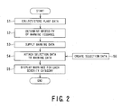
- Fig. 2 is a flowchart of a monitoring operation performed by the plant monitoring apparatus according to the embodiment of the present invention;
- Fig. 3 is a dataflow diagram of monitoring operation associated with the number of warnings performed by the plant monitoring apparatus according to the embodiment of the present invention;
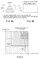
- Fig. 4A is a conceptual diagram showing processing of data employed by the plant monitoring apparatus according to the embodiment of the present invention, and Fig. 4B is an example of a screen configuration employed by the plant monitoring apparatus according to the embodiment of the present invention;
- Fig. 5 is an example of a screen displayed on a display/setting unit of the plant monitoring apparatus according to the embodiment of the preset invention; and
- Fig. 6 is a conceptual diagram of a known plant monitoring apparatus.
- A plant monitoring apparatus according to an embodiment of the present invention will be described hereunder with reference to the accompanying drawings.
- With reference to Fig. 1, a
plant monitoring apparatus 1 according to the embodiment of the invention includes apower generation plant 2, aprocess measuring unit 3, awarning determining unit 4, awarning selecting unit 5, adisplay processing unit 6, a display/setting unit 7, a warningcriteria supplying unit 8, awarning criteria database 9, and a warningcriteria setting unit 10. - In these units or like, functions of the
process measuring unit 3, thewarning determining unit 4, thewarning selecting unit 5, thedisplay processing unit 6, the display/setting unit 7, the warningcriteria supplying unit 8, thewarning criteria database 9, and the warningcriteria setting unit 10 are implemented by programs causing a computer to operate. - Hereunder, functions of and interrelations between the respective units will be described.
- The
process measuring unit 3 periodically collects process values at each input point of thepower generation plant 2, and stores the process values in a plant data storage unit 3a. - The
warning determining unit 4 loads the plant data stored in the plant data storage unit 3a and determines whether warning or warnings are to be issued on the basis of a predetermined criterion. - The
warning selecting unit 5 adds selection data, which is described below, loaded from the warningcriteria supplying unit 8 to the warning data supplied from thewarning determining unit 4. Thewarning selecting unit 5 also compares the warning data with one or more classification criteria supplied from the warningcriteria supplying unit 8 so as to classify the warnings into a plurality of categories. - The display/
setting unit 7 loads the warning data, attached with the selection data by thewarning selecting unit 5, through thedisplay processing unit 6 and displays plant monitoring information to operators. In addition, in response to an interaction request from the operators, the display/setting unit 7 receives information on system screens and on monitoring range specification. - The
warning criteria database 9 is accessed by the display/setting unit 7 through the warningcriteria setting unit 10. The warningcriteria supplying unit 8 loads warning criteria from thewarning criteria database 9. - Next, with reference to a flowchart of Fig. 2, a monitoring operation performed by the plant monitoring apparatus will be described.
- As shown in Figs. 1 to 3, the
plant measuring unit 3 periodically collects the process values at each input point of thepower generation plant 2 and stores the process values in the plant data storage unit 3a (step S1). - The
warning determining unit 4 loads the plant data stored in the plant data storage unit 3a and compares the plant data with a warning issuance criterion so as to determine whether or not issuance of warnings is necessary (step S2). - The
warning determining unit 4 selects only data indicating the necessity of the issuance of the warnings from the loaded plant data so as to reduce the amount of warning data. - The
warning determining unit 4 supplies the data determined to indicate the necessity of the issuance of the warnings to thewarning selecting unit 5 as the warning data (step S3). - The
warning selecting unit 5 loads the selection data from thewarning criteria database 9 through the warningcriteria supplying unit 8. Thewarning selecting unit 5 attaches the selection data to the warning data supplied from the warning determining unit 4 (step S4). - Fig. 4A shows processing performed on data supplied to the display/
setting unit 7 through thedisplay processing unit 6, whereas Fig. 4B shows an example of a screen configuration. - As shown in Figs. 4A and 4B, the selection data attached by the
warning selecting unit 5 may indicate, for example, warning severity levels, such as "high", "intermediate", and "low". Referring to Fig. 4A, a vertical direction of a cone shows the warning severity levels, such as "high", "intermediate", and "low". A section of the cone in the horizontal direction conceptually shows the number of issued warnings. This example shows a circumstance where the number of "high" level warnings is few, whereas the number of warnings increases as the severity level goes down to "intermediate" and "low". - The warning data attached with the selection data by the
warning selecting unit 5 is provided to the display/setting unit 7 through thedisplay processing unit 6. The warnings corresponding to the warning data are classified into each category according to the categories of the selection data and are displayed on the display/setting unit 7 (step S5). - As shown in Fig. 4B, the classified warnings may be shown in different screens displayed on the display/
setting unit 7 according to the classification criteria. For example, three hierarchical screens are displayed simultaneously and superimposed on top of each other using tags. These three screens correspond to the warning severity levels, e.g., "high", "intermediate" and "low". - More specifically, as shown in Fig. 3, the warnings having the selection data classified into the "high" severity level are displayed on a "high" level screen. Warnings having the selection data classified into the "high" and "intermediate" severity levels are displayed on a "intermediate" level screen. Likewise, the warnings having the selection data classified into the "high", "intermediate", and "low" severity levels are displayed on a "low" level screen. That is, all the warnings are displayed on the "low" level screen. Accordingly, the warnings are displayed with the number of warnings decreasing as the severity level increases. Particularly, the "high" level screen shows an extremely small number of warnings, which can prevent operators from missing the critical warnings and can ensure safety. Furthermore, the "low" level screen shows all the warnings, which allows operators to recognize the operational state of the plant through the number of warnings.
- Hereunder, a step of generating the selection data (step S6) used at step S4 will be described.
- Fig. 5 shows a screen example displayed on the display/
setting unit 7, in which the warning criteria data is set in thewarning criteria database 9 through the warningcriteria setting unit 10 using the screen example. - As shown in Fig. 5, in the present embodiment, each warning is rated for two factors, that is, the first one is the severity level and the second one is a signal level.
- In this example, the severity level, i.e., the first factor, is rated within a range of 0 to 1. For example, the severity level of a warning about an error in a printer connected to a plant monitoring apparatus is set at 0.2, whereas the severity level of a warning about boiler temperature is set at 0.8. The error in the printer connected to the plant monitoring apparatus does not have to be fixed until the printer is used. However, the high temperature in the boiler may cause a failure in an operation of the plant if the warning thereof is ignored. Since the warning about the high temperature in the boiler is more critical than the error in the printer, a higher value is granted to the warning about the high temperature in the boiler.
- In addition, the signal level, i.e., the second factor, indicates a level regarding process quantities of each process element to be monitored. For example, the signal level corresponds to E shown by the following
Equation 1, wherein T represents the temperature of the boiler, TU represents the allowable upper limit, and TL represents the lower limit.
- In the setting screen shown in Fig. 5, the severity level, i.e., the first factor, and the signal level, i.e., the second factor, are plotted as abscissa and ordinate, respectively. An area showing warning issuance is divided into a plurality of ranges.
- These ranges allow operators to specify a range corresponding to the warning severity level, such as "high" or "intermediate". In this case, the rest of the ranges correspond to a range of the "low" warning severity level. In addition, the plant monitoring apparatus may be configured to specify an area (e.g., the upper right area shown in Fig. 5) where both the signal level and the severity level are highest as a range corresponding to the "high" severity level. At this time, a method allowing operators to interactively set the warning ranges using a mouse may be used.
- Preferably, each area may have a function for displaying the number of warnings currently issued. This allows operators to specify the total number of warnings to be displayed for confirmation. Additionally, at this time, it is preferable to display the warnings located at the "high" level range determined by the specification. Furthermore, preferably, the plant monitoring apparatus may have a function for displaying a screen showing current settings in order to allow operators to confirm the current warning display ranges when other operators take over from the current operators.
- Accordingly, a large amount of warning data is classified into the severity levels, such as "high", "intermediate", and "low" and is displayed. This allows operators to be efficiently notified of a plurality of critical warnings.
- As described above, an embodiment of the present invention implements a plant monitoring apparatus capable of efficiently notifying operators or the like of a plurality of critical warnings among many warnings by providing a warning selecting unit between a warning determining unit and a display processing unit.
Claims (8)
- A plant monitoring apparatus comprising:a process measuring unit configured to store data of a plant;a warning determining unit operatively connected to a process measuring unit and configured to determine a plurality of warning data to be issued as warnings from a large amount of process data collected by the process measuring unit on the basis of a preliminarily set criterion;a warning selecting unit operatively connected to the warning determining unit and configured to compare the plurality of warning data with one or more classification criteria;a display/setting unit operatively connected to the warning selecting unit and configured to display the warning data to an operator through a display processing unit;a warning criteria database operatively connected to the display/setting unit and configured to access the selected data through a warning criteria setting unit; anda warning criteria supplying unit operatively connected to the warning criteria database and configured to load a warning criteria from the warning criteria database to the warning selecting unit,wherein the warning selecting unit compares the plurality of warning data with one or more classification criteria supplied by the warning criteria supplying unit so as to classify the plurality of warning data, and the warnings are classified into categories according to the classification and the classified warnings are displayed on the display/setting unit.
- The apparatus according to claim 1, wherein the classified warnings are displayed on different screens for each classification criterion.
- The apparatus according to claim 2, wherein the different screens are hierarchical screens.
- The apparatus according to claim 1, wherein the display/ setting unit writes data in the warning criteria database through the warning criteria setting unit, and a screen displayed thereon allows specification of selected ranges of the warnings displayed according to one or more classification criteria.
- The apparatus according to claim 4, wherein the selected ranges include a range written in the warning criteria database through the warning criteria setting unit and a range predetermined according to the classification criteria.
- The apparatus according to claim 4, wherein the screen allowing the specification of the selected ranges of the warnings shows the number of warnings to be displayed when a currently specified range is selected.
- The apparatus according to claim 4, wherein the selected ranges of the warnings are displayed on a screen.
- A plant monitoring method comprising the steps of:collecting and storing plant data obtained from a plant;comparing the stored plant data with warning set criteria and determining a plurality of warning data to be issued as warnings on the basis of a preliminarily set criterion;transmitting and selecting data determined to be warned;attaching the warning data to the selected data; andclassifying the warnings into categories according to the classification and displaying the classified warnings.
Applications Claiming Priority (1)
| Application Number | Priority Date | Filing Date | Title |
|---|---|---|---|
| JP2006008653A JP4564452B2 (en) | 2006-01-17 | 2006-01-17 | Plant monitoring device |
Publications (2)
| Publication Number | Publication Date |
|---|---|
| EP1811354A1 true EP1811354A1 (en) | 2007-07-25 |
| EP1811354B1 EP1811354B1 (en) | 2009-12-23 |
Family
ID=37946166
Family Applications (1)
| Application Number | Title | Priority Date | Filing Date |
|---|---|---|---|
| EP07000769A Ceased EP1811354B1 (en) | 2006-01-17 | 2007-01-16 | Plant monitoring apparatus |
Country Status (6)
| Country | Link |
|---|---|
| US (1) | US7652567B2 (en) |
| EP (1) | EP1811354B1 (en) |
| JP (1) | JP4564452B2 (en) |
| CN (1) | CN101004850A (en) |
| AU (1) | AU2006252208B1 (en) |
| DE (1) | DE602007003865D1 (en) |
Cited By (4)
| Publication number | Priority date | Publication date | Assignee | Title |
|---|---|---|---|---|
| US20110060476A1 (en) * | 2009-09-09 | 2011-03-10 | Yutaka Iino | Energy management system and energy management method |
| EP2390743A1 (en) * | 2010-05-31 | 2011-11-30 | Siemens Aktiengesellschaft | Method for monitoring the process of a control formula in a batch procedure |
| US9024955B2 (en) | 2010-04-14 | 2015-05-05 | Yokogawa Electric Corporation | Method and system for displaying proiritized live thumbnail of process graphic views |
| EP3489779A1 (en) * | 2017-11-22 | 2019-05-29 | Airbus Operations S.A.S. | Aircraft assembly tracker systems and methods |
Families Citing this family (18)
| Publication number | Priority date | Publication date | Assignee | Title |
|---|---|---|---|---|
| US8125310B2 (en) * | 2005-04-01 | 2012-02-28 | Abb Research Ltd. | Method and system for providing a user interface |
| JP4935555B2 (en) * | 2007-07-19 | 2012-05-23 | 横河電機株式会社 | Alarm engineering support device |
| JP2009217723A (en) * | 2008-03-12 | 2009-09-24 | Oki Electric Ind Co Ltd | Monitoring device and program |
| WO2010016113A1 (en) * | 2008-08-06 | 2010-02-11 | 三菱電機株式会社 | Plant monitoring control system |
| DE102008055585B3 (en) * | 2008-12-23 | 2010-04-29 | Jiri Burda | Modular heating and lighting system for the construction of lighting and heating elements |
| JP5535604B2 (en) * | 2009-12-11 | 2014-07-02 | 三菱重工業株式会社 | Control display system, method and program |
| US8797189B2 (en) | 2011-03-22 | 2014-08-05 | Mitsubishi Heavy Industries, Ltd. | Control display system, method, and program |
| RU2450335C1 (en) * | 2011-07-11 | 2012-05-10 | Федеральное государственное военное образовательное учреждение высшего профессионального образования "Военная академия связи имени маршала Советского Союза С.М. Буденного" Министерства обороны Российской Федерации | Method for distributed monitoring and adaptive control of multilevel system and apparatus for realising said method |
| US8659415B2 (en) * | 2011-07-15 | 2014-02-25 | General Electric Company | Alarm management |
| KR101250750B1 (en) * | 2011-09-08 | 2013-04-04 | 한전원자력연료 주식회사 | Real-time monitoring system for spent fuel pool and method thereof |
| JP5802575B2 (en) * | 2012-02-27 | 2015-10-28 | 株式会社東芝 | Plant monitoring apparatus, control method, and control program |
| US9493219B2 (en) | 2012-03-05 | 2016-11-15 | Furuno Electric Co., Ltd. | Alarm display device, integrated navigation system including the same and method of displaying alarms |
| CN104157104B (en) * | 2013-05-15 | 2017-02-15 | 北京捷诺视讯数码科技有限公司 | Running state analysis alarm module, system and method |
| US9875640B2 (en) * | 2015-04-08 | 2018-01-23 | General Electric Company | Method and system for managing plant alarm systems |
| US20160349931A1 (en) * | 2015-05-28 | 2016-12-01 | Rockwell Automation Technologies, Inc. | Responsive user interface for an industrial environment |
| CN104867278A (en) * | 2015-05-29 | 2015-08-26 | 安徽康成工业产品设计有限公司 | Automatic level-dividing mechanical reminding device |
| CN109065197B (en) * | 2018-06-28 | 2021-11-16 | 中国核电工程有限公司 | Alarm classification processing method and system for pressurized water reactor nuclear power plant |
| JP6604455B1 (en) * | 2019-05-16 | 2019-11-13 | 横河電機株式会社 | Display control method, display control apparatus, and program |
Citations (4)
| Publication number | Priority date | Publication date | Assignee | Title |
|---|---|---|---|---|
| US5581242A (en) * | 1991-08-22 | 1996-12-03 | Hitachi, Ltd. | Automatic alarm display processing system in plant |
| US20020055790A1 (en) * | 2000-11-07 | 2002-05-09 | Havekost Robert B. | Enhanced device alarms in a process control system |
| WO2003075206A2 (en) * | 2002-03-01 | 2003-09-12 | Fisher-Rosemount Systems, Inc. | Integrated alert generation in a process plant |
| US20040139085A1 (en) * | 2002-12-30 | 2004-07-15 | Evren Eryurek | Data visualization within an integrated asset data system for a process plant |
Family Cites Families (10)
| Publication number | Priority date | Publication date | Assignee | Title |
|---|---|---|---|---|
| JPH01263793A (en) * | 1988-04-14 | 1989-10-20 | Toshiba Corp | Process display device |
| US5400246A (en) * | 1989-05-09 | 1995-03-21 | Ansan Industries, Ltd. | Peripheral data acquisition, monitor, and adaptive control system via personal computer |
| JPH03266100A (en) * | 1990-03-16 | 1991-11-27 | Fujitsu Ltd | System for monitoring alarm setting plural conditions |
| JPH05174274A (en) * | 1991-12-24 | 1993-07-13 | Yokogawa Electric Corp | Alarm display device |
| JP3445409B2 (en) * | 1995-06-12 | 2003-09-08 | 東芝システムテクノロジー株式会社 | Plant alarm monitoring device |
| JPH11327636A (en) | 1998-05-07 | 1999-11-26 | Mitsubishi Electric Corp | Plant condition monitoring device |
| JP4130289B2 (en) * | 2000-03-23 | 2008-08-06 | 株式会社東芝 | Power generation operation system |
| US6492901B1 (en) * | 2000-05-10 | 2002-12-10 | Westinghouse Electric Company Llc | Alarm management system |
| JP2002117468A (en) | 2000-10-11 | 2002-04-19 | Mitsubishi Heavy Ind Ltd | Plant operation diagnosis and support system |
| JP2003058967A (en) * | 2001-08-22 | 2003-02-28 | Yokogawa Electric Corp | Alarm device |
-
2006
- 2006-01-17 JP JP2006008653A patent/JP4564452B2/en not_active Expired - Fee Related
- 2006-12-21 AU AU2006252208A patent/AU2006252208B1/en not_active Ceased
-
2007
- 2007-01-12 US US11/652,511 patent/US7652567B2/en not_active Expired - Fee Related
- 2007-01-16 CN CNA200710001752XA patent/CN101004850A/en active Pending
- 2007-01-16 DE DE602007003865T patent/DE602007003865D1/en active Active
- 2007-01-16 EP EP07000769A patent/EP1811354B1/en not_active Ceased
Patent Citations (4)
| Publication number | Priority date | Publication date | Assignee | Title |
|---|---|---|---|---|
| US5581242A (en) * | 1991-08-22 | 1996-12-03 | Hitachi, Ltd. | Automatic alarm display processing system in plant |
| US20020055790A1 (en) * | 2000-11-07 | 2002-05-09 | Havekost Robert B. | Enhanced device alarms in a process control system |
| WO2003075206A2 (en) * | 2002-03-01 | 2003-09-12 | Fisher-Rosemount Systems, Inc. | Integrated alert generation in a process plant |
| US20040139085A1 (en) * | 2002-12-30 | 2004-07-15 | Evren Eryurek | Data visualization within an integrated asset data system for a process plant |
Non-Patent Citations (2)
| Title |
|---|
| HENNINGSEN A ET AL: "Intelligent alarm handling in cement plants-lessons learned from the nuclear industry", CEMENT INDUSTRY TECHNICAL CONFERENCE, 1993. RECORD OF CONFERENCE PAPERS., 35TH IEEE TORONTO, ONT., CANADA 23-27 MAY 1993, NEW YORK, NY, USA,IEEE, US, 23 May 1993 (1993-05-23), pages 165 - 182, XP010111092, ISBN: 0-7803-0960-X * |
| TUSZYNSKI, LARSSON, NIHLWING, ÖHMAN, CALZADA: "A Pilot Project on Alarm Reduction and Presentation Based on Multilevel Flow Models", PROCEEDINGS OF THE ENLARGED HALDEN PROGRAMME GROUP MEETING, 2002, Norway, XP002430903 * |
Cited By (6)
| Publication number | Priority date | Publication date | Assignee | Title |
|---|---|---|---|---|
| US20110060476A1 (en) * | 2009-09-09 | 2011-03-10 | Yutaka Iino | Energy management system and energy management method |
| US8612062B2 (en) * | 2009-09-09 | 2013-12-17 | Kabushiki Kaisha Toshiba | Energy management system and energy management method |
| US9024955B2 (en) | 2010-04-14 | 2015-05-05 | Yokogawa Electric Corporation | Method and system for displaying proiritized live thumbnail of process graphic views |
| EP2390743A1 (en) * | 2010-05-31 | 2011-11-30 | Siemens Aktiengesellschaft | Method for monitoring the process of a control formula in a batch procedure |
| US8670854B2 (en) | 2010-05-31 | 2014-03-11 | Siemens Aktiengesellschaft | Method for monitoring sequencing of a control recipe for a batch process |
| EP3489779A1 (en) * | 2017-11-22 | 2019-05-29 | Airbus Operations S.A.S. | Aircraft assembly tracker systems and methods |
Also Published As
| Publication number | Publication date |
|---|---|
| EP1811354B1 (en) | 2009-12-23 |
| US7652567B2 (en) | 2010-01-26 |
| CN101004850A (en) | 2007-07-25 |
| JP2007193419A (en) | 2007-08-02 |
| DE602007003865D1 (en) | 2010-02-04 |
| US20070172018A1 (en) | 2007-07-26 |
| JP4564452B2 (en) | 2010-10-20 |
| AU2006252208B1 (en) | 2007-06-21 |
Similar Documents
| Publication | Publication Date | Title |
|---|---|---|
| US7652567B2 (en) | Plant monitoring apparatus and plant monitoring method | |
| KR102355777B1 (en) | Process anomalous state diagnostic device and process anomalous state diagnosis method | |
| US7065433B2 (en) | Vehicle monitoring and reporting system and method | |
| US5754451A (en) | Preventative maintenance and diagonstic system | |
| DE10154534B4 (en) | Integrated alarm display in a process control network | |
| EP2732348B1 (en) | Method and apparatus for monitoring an operational state of a system on the basis of telemetry data | |
| US8489209B2 (en) | Method for analyzing and diagnosing large scale process automation control systems | |
| KR20020094032A (en) | Alarm management system | |
| US9208012B2 (en) | Display processing system, display processing method, and program | |
| EP2824555A1 (en) | Alert display device, integrated navigation system equipped with same, and alert display method | |
| US20130135113A1 (en) | Instrument status displaying device and instrument status displaying method | |
| WO2013041440A1 (en) | System and method for plant wide asset management | |
| JP4458349B2 (en) | Device diagnostic device, operation program thereof, device diagnostic method | |
| US10691118B2 (en) | Information retrieval system and method | |
| US9720015B2 (en) | Intelligent visualization in the monitoring of process and/or system variables | |
| US10955837B2 (en) | Method and system for error detection and monitoring for an electronically closed-loop or open-loop controlled machine part | |
| JP2021047523A (en) | Abnormality sign detection device, method and program | |
| CN100373278C (en) | Confirmation method of process event occurrence history | |
| JP2017126333A (en) | A method for process operators to personalize settings to enable detection of abnormal process behavior | |
| JP4197466B2 (en) | How to display process event occurrence history | |
| EP4286608A1 (en) | Display device and work machine | |
| JP2019204342A (en) | Sign diagnosis system | |
| US6400282B1 (en) | System for monitoring the operation of an aircraft, especially a helicopter | |
| KR101070369B1 (en) | Operation signal selection device and industrial computer-readable recording medium of industrial plant | |
| EP4083584A1 (en) | Method for evaluating the performance of a dynamic weighing instrument, weighing system and computer program |
Legal Events
| Date | Code | Title | Description |
|---|---|---|---|
| PUAI | Public reference made under article 153(3) epc to a published international application that has entered the european phase |
Free format text: ORIGINAL CODE: 0009012 |
|
| 17P | Request for examination filed |
Effective date: 20070116 |
|
| AK | Designated contracting states |
Kind code of ref document: A1 Designated state(s): AT BE BG CH CY CZ DE DK EE ES FI FR GB GR HU IE IS IT LI LT LU LV MC NL PL PT RO SE SI SK TR |
|
| AX | Request for extension of the european patent |
Extension state: AL BA HR MK YU |
|
| 17Q | First examination report despatched |
Effective date: 20070830 |
|
| AKX | Designation fees paid |
Designated state(s): DE |
|
| GRAP | Despatch of communication of intention to grant a patent |
Free format text: ORIGINAL CODE: EPIDOSNIGR1 |
|
| RTI1 | Title (correction) |
Free format text: PLANT MONITORING APPARATUS |
|
| RIN1 | Information on inventor provided before grant (corrected) |
Inventor name: IINO, YUTAKA Inventor name: YAMASAKI, MASUO Inventor name: TAKAGI, YASUO Inventor name: NAKAI, AKIMASA Inventor name: MURAYAMA, DAI |
|
| GRAS | Grant fee paid |
Free format text: ORIGINAL CODE: EPIDOSNIGR3 |
|
| GRAA | (expected) grant |
Free format text: ORIGINAL CODE: 0009210 |
|
| AK | Designated contracting states |
Kind code of ref document: B1 Designated state(s): DE |
|
| REF | Corresponds to: |
Ref document number: 602007003865 Country of ref document: DE Date of ref document: 20100204 Kind code of ref document: P |
|
| PLBE | No opposition filed within time limit |
Free format text: ORIGINAL CODE: 0009261 |
|
| STAA | Information on the status of an ep patent application or granted ep patent |
Free format text: STATUS: NO OPPOSITION FILED WITHIN TIME LIMIT |
|
| 26N | No opposition filed |
Effective date: 20100924 |
|
| PGFP | Annual fee paid to national office [announced via postgrant information from national office to epo] |
Ref country code: DE Payment date: 20190102 Year of fee payment: 13 |
|
| PGFP | Annual fee paid to national office [announced via postgrant information from national office to epo] |
Ref country code: DE Payment date: 20190102 Year of fee payment: 13 |
|
| REG | Reference to a national code |
Ref country code: DE Ref legal event code: R119 Ref document number: 602007003865 Country of ref document: DE |
|
| PG25 | Lapsed in a contracting state [announced via postgrant information from national office to epo] |
Ref country code: DE Free format text: LAPSE BECAUSE OF NON-PAYMENT OF DUE FEES Effective date: 20200801 |