EP1811262A1 - Energetic thin-film initiator - Google Patents
Energetic thin-film initiator Download PDFInfo
- Publication number
- EP1811262A1 EP1811262A1 EP06124113A EP06124113A EP1811262A1 EP 1811262 A1 EP1811262 A1 EP 1811262A1 EP 06124113 A EP06124113 A EP 06124113A EP 06124113 A EP06124113 A EP 06124113A EP 1811262 A1 EP1811262 A1 EP 1811262A1
- Authority
- EP
- European Patent Office
- Prior art keywords
- thin film
- initiator
- film layers
- layers
- ignition
- Prior art date
- Legal status (The legal status is an assumption and is not a legal conclusion. Google has not performed a legal analysis and makes no representation as to the accuracy of the status listed.)
- Withdrawn
Links
Images
Classifications
-
- F—MECHANICAL ENGINEERING; LIGHTING; HEATING; WEAPONS; BLASTING
- F42—AMMUNITION; BLASTING
- F42B—EXPLOSIVE CHARGES, e.g. FOR BLASTING, FIREWORKS, AMMUNITION
- F42B3/00—Blasting cartridges, i.e. case and explosive
- F42B3/10—Initiators therefor
- F42B3/11—Initiators therefor characterised by the material used, e.g. for initiator case or electric leads
Definitions
- the present invention relates to energetic material initiators.
- the initiation of an energetic material requires that a stable and reliable fuze mechanism activate the chemical reaction at a desired time.
- Fuzes are often used in conjunction with a safe and arm mechanism.
- Electronic Safe and Arm Fuze (ESAF) designs are increasingly being used due to their flexibility in state sensing, response logic and use of electricity as the initiating power source.
- the initiator is the component of the ESAF that converts the electrical energy to a form that can initiate the energetic material.
- the finished initiator package volume, the cost of initiator fabrication, the repeatability of initiator fabrication, and the required power to initiate an energetic chemical reaction must be minimized while reliability, resistance to misfire, and durability must be maximized for optimum service.
- Electro-Explosive Devices typically incorporate hot wire, semiconductor bridge, or exploding foil type initiators.
- Existing types of EEDs involve resistance heating (and relatively high power) to produce a high temperature used to trigger a fuze chain or energetic material.
- Existing devices that employ thin films include the following references..
- J.M. Boyd "Thin-Film Electric Initiator -- Application Of Explosives And Performance Tests", Defense Technical Information Center Report No. HDL-TR-1414 (1969 ), discloses a thin film deposited chemically that does not comprise a reactive material. The film produces a high temperature when a relatively high electrical current is applied across it.
- U.S. Patent No. 5,732,634 titled “Thin Film Bridge Initiators and Method of Manufacture", to Flickinger, et al., discloses a vapor deposited thin film that produces a high temperature when a relatively high current is passed through it. Again, the film does not comprise a reactive material.
- U.S. Patent No. 6,276,276 titled “Thin-Film Optical Initiator", to Erickson, discloses a film used in conjunction with an optical power input (laser). The laser heats a thin-film material which produces a high temperature which then initiates an output charge.
- EFI Exploding Film Initiator
- the present invention is of an energetic thin film initiator and a method of making same, comprising: providing a plurality of thin film layers of fuel; providing a plurality of thin film layers of oxidizer, at least one interposed between two of the thin layers of fuel; and providing an electrical input to the thin film layers that upon receipt of an electrical pulse causes ignition of layers of fuel and oxidizer.
- the electrical input comprises a pair of conductive electrical leads.
- a silicon wafer substrate is preferred for the thin film layers.
- An electrical pulse of less than or equal to approximately 2 watts causes ignition.
- a resultant temperature of the ignition is preferably at least approximately 4600 degrees F..
- the thin film layers are tailored for one or more properties selected from stored chemical energy content, maximum achievable reaction temperature, maximum reaction rate, deposition thickness, and required deposition area.
- the thin film layers have a thickness of less than approximately 100 micrometers for appropriate applications and less than approximately 100 nanometers for others.
- the ignition primarily results from free energy release associated with intermetallic reactions or from free energy release associated with oxidation-reduction reactions.
- the present invention relates to the production of an electro-explosive device (EED) utilizing an exploding film initiator (EFI).
- EED electro-explosive device
- EFI exploding film initiator
- this invention relates to the production of an EED by the application of a multilayered thin-film EFI.
- an energetic structure is fabricated by depositing layers of reactants onto a selected substrate.
- the adjacent reactants form a repeating unit that is duplicated multiple times during the thin-film deposition process until sufficient quantity of material is accumulated on the substrate to function as an energetic initiator.
- a pair of electrical leads can supply a relatively low voltage to the thin-film structure resulting in ohmic heating and reaction of the initiator.
- This reaction is rapid and produces a high-temperature that, when placed in contact with a fuze chain or another energetic material, results in the triggering of another event.
- Relatively low power is required to produce sufficient heat within the energetic material to release the chemical energy within this type of initiator, and the fabrication process can be fully automated to produce structures that have consistent reaction properties.
- Thin film deposition processes permit precise control over the deposited structure geometry in such a way that the initiator can be tailored for a variety of applications..
- Thin-film deposition processes also permit the deposition of insulating structures to electrically, thermally, or physically isolate the initiator from its surrounding environment.
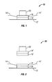
- Figs. 1-2 show the preferred embodiments 10,30 of the invention, albeit not to scale.
- the energetic thin film initiator of the invention comprises a pair of layers 16,18 preferably on substrate 12, one layer of which comprises fuel and the other oxidizer. Electrical conductors 14,14' carry electrical impulses. The initiator ignites secondary energetic material 20.
- a plurality of pairs of layers of fuel/oxidizer are employed.
- a thin-film initiator can be deposited on a silicon wafer substrate.
- the substrate is in part used to retain/protect thin-film initiator during handling.
- the deposited material reaction begins.
- the resultant temperature of the thin-film reaction might be, for example, about 4600 degrees F; but again, can be tailored by design the thin film deposition thickness of the various layers and the selected deposition materials.
- the deposited materials are selected for tailored performance regarding properties such as stored chemical energy content, maximum achievable reaction temperature, and maximum reaction rate, traded against deposition thickness and required deposition area. Exothermic reaction of deposited materials result from the free energy release associated with intermetallic reactions, or from oxidation-reduction reactions.
- the selected reactive materials are deposited such that reactants are positioned in close proximity (nanometer (i.e., thin films of thickness less than approximately 100 nanometers) or micrometer (i.e., thin films of thickness less than approximately 100 micrometers) scale). Repeated deposition of reactants in a layered structure increases the stored energy content per unit area.
- thermodynamic approaches to analysis S. H.. Fischer and M. C. Grubelich, "A Survey of Combustible Metals, Thermites, and Intermetallics for Pyrotechnic Applications," American Institute of Aeronautics and Astronautics Paper AIAA-96-3018 (1996 ).
- the initiator of the invention produces high thermal energy when a relatively low electrical input is applied to the material releasing stored chemical energy.
- the device can be fabricated using a variety of thin-film deposition techniques to tailor the input (activation) requirements for initiation, and the resultant output properties to suit the application
- an electrical impulse is applied to the initiator material, it starts a chemical reaction that releases stored chemical energy producing a high temperature. This resultant high temperature is much greater than the electrical impulse could have produced by itself.
Landscapes
- Engineering & Computer Science (AREA)
- General Engineering & Computer Science (AREA)
- Physical Or Chemical Processes And Apparatus (AREA)
- Chemical Vapour Deposition (AREA)
Abstract
Description
- Not Applicable.
- Not Applicable..
- Not Applicable.
- Not Applicable.
- The present invention relates to energetic material initiators.
- The initiation of an energetic material requires that a stable and reliable fuze mechanism activate the chemical reaction at a desired time. Fuzes are often used in conjunction with a safe and arm mechanism.. Electronic Safe and Arm Fuze (ESAF) designs are increasingly being used due to their flexibility in state sensing, response logic and use of electricity as the initiating power source. The initiator is the component of the ESAF that converts the electrical energy to a form that can initiate the energetic material. The finished initiator package volume, the cost of initiator fabrication, the repeatability of initiator fabrication, and the required power to initiate an energetic chemical reaction must be minimized while reliability, resistance to misfire, and durability must be maximized for optimum service.
- Electro-Explosive Devices (EEDs) typically incorporate hot wire, semiconductor bridge, or exploding foil type initiators. Existing types of EEDs involve resistance heating (and relatively high power) to produce a high temperature used to trigger a fuze chain or energetic material. Existing devices that employ thin films include the following references..
- J.M. Boyd, "Thin-Film Electric Initiator -- Application Of Explosives And Performance Tests", Defense Technical Information Center Report No. HDL-TR-1414 (1969), discloses a thin film deposited chemically that does not comprise a reactive material. The film produces a high temperature when a relatively high electrical current is applied across it.
-
U.S. Patent No. 5,732,634 , titled "Thin Film Bridge Initiators and Method of Manufacture", to Flickinger, et al., discloses a vapor deposited thin film that produces a high temperature when a relatively high current is passed through it. Again, the film does not comprise a reactive material. -
U.S. Patent No. 6,276,276 , titled "Thin-Film Optical Initiator", to Erickson, discloses a film used in conjunction with an optical power input (laser).. The laser heats a thin-film material which produces a high temperature which then initiates an output charge. - The use of the multilayered thin film Exploding Film Initiator (EFI) of the invention provides a greater initial energy output then a conventional EFI for an equivalent input energy and can be tailored for initiation sensitivity and maximum achievable temperature. Once initiated, relatively high temperatures can be reached by the EFI through the release of chemically stored energy upon reaction of the EFI component materials.
- The present invention is of an energetic thin film initiator and a method of making same, comprising: providing a plurality of thin film layers of fuel; providing a plurality of thin film layers of oxidizer, at least one interposed between two of the thin layers of fuel; and providing an electrical input to the thin film layers that upon receipt of an electrical pulse causes ignition of layers of fuel and oxidizer. In the preferred embodiment, the electrical input comprises a pair of conductive electrical leads. A silicon wafer substrate is preferred for the thin film layers. An electrical pulse of less than or equal to approximately 2 watts causes ignition. A resultant temperature of the ignition is preferably at least approximately 4600 degrees F.. The thin film layers are tailored for one or more properties selected from stored chemical energy content, maximum achievable reaction temperature, maximum reaction rate, deposition thickness, and required deposition area. The thin film layers have a thickness of less than approximately 100 micrometers for appropriate applications and less than approximately 100 nanometers for others. The ignition primarily results from free energy release associated with intermetallic reactions or from free energy release associated with oxidation-reduction reactions.
- Objects, advantages and novel features, and further scope of applicability of the present invention will be set forth in part in the detailed description to follow, taken in conjunction with the accompanying drawings, and in part will become apparent to those skilled in the art upon examination of the following, or may be learned by practice of the invention. The objects and advantages of the invention may be realized and attained by means of the instrumentalities and combinations particularly pointed out in the appended claims.
- The accompanying drawings, which are incorporated into and form a part of the specification, illustrate one or more embodiments of the present invention and, together with the description, serve to explain the principles of the invention. The drawings are only for the purpose of illustrating one or more preferred embodiments of the invention and are not to be construed as limiting the invention. In the drawings:
- Fig 1 is a schematic diagram of a first embodiment of the invention; and
- Fig. 2 is a schematic diagram of a second embodiment of the invention.
- The present invention relates to the production of an electro-explosive device (EED) utilizing an exploding film initiator (EFI). In particular this invention relates to the production of an EED by the application of a multilayered thin-film EFI. Using developed and highly repeatable batch processing approaches involving thin-film deposition, an energetic structure is fabricated by depositing layers of reactants onto a selected substrate. The adjacent reactants form a repeating unit that is duplicated multiple times during the thin-film deposition process until sufficient quantity of material is accumulated on the substrate to function as an energetic initiator. Among other possible initiation methods, a pair of electrical leads can supply a relatively low voltage to the thin-film structure resulting in ohmic heating and reaction of the initiator. This reaction is rapid and produces a high-temperature that, when placed in contact with a fuze chain or another energetic material, results in the triggering of another event. Relatively low power is required to produce sufficient heat within the energetic material to release the chemical energy within this type of initiator, and the fabrication process can be fully automated to produce structures that have consistent reaction properties. Thin film deposition processes permit precise control over the deposited structure geometry in such a way that the initiator can be tailored for a variety of applications.. Thin-film deposition processes also permit the deposition of insulating structures to electrically, thermally, or physically isolate the initiator from its surrounding environment.
- Figs. 1-2 show the
preferred embodiments layers substrate 12, one layer of which comprises fuel and the other oxidizer.Electrical conductors 14,14' carry electrical impulses. The initiator ignites secondaryenergetic material 20. In Fig. 2, a plurality of pairs of layers of fuel/oxidizer are employed. - For example, a thin-film initiator can be deposited on a silicon wafer substrate. The substrate is in part used to retain/protect thin-film initiator during handling. After experiencing an electrical impulse (on the order of 2 watts or less) or other sufficiently initiating stimulus, the deposited material reaction begins. The resultant temperature of the thin-film reaction might be, for example, about 4600 degrees F; but again, can be tailored by design the thin film deposition thickness of the various layers and the selected deposition materials.
- The deposited materials are selected for tailored performance regarding properties such as stored chemical energy content, maximum achievable reaction temperature, and maximum reaction rate, traded against deposition thickness and required deposition area. Exothermic reaction of deposited materials result from the free energy release associated with intermetallic reactions, or from oxidation-reduction reactions. The selected reactive materials are deposited such that reactants are positioned in close proximity (nanometer (i.e., thin films of thickness less than approximately 100 nanometers) or micrometer (i.e., thin films of thickness less than approximately 100 micrometers) scale). Repeated deposition of reactants in a layered structure increases the stored energy content per unit area.
- A great multitude of intermetallic reactants and oxidation-reduction reactants are capable of producing energy once initiated. For a partial review of these reactions and the energy content (per unit mass, and volume), maximum adiabatic temperature rise using thermodynamic approaches to analysis, refer to S. H.. Fischer and M. C. Grubelich, "A Survey of Combustible Metals, Thermites, and Intermetallics for Pyrotechnic Applications," American Institute of Aeronautics and Astronautics Paper AIAA-96-3018 (1996).
- To reiterate, the initiator of the invention produces high thermal energy when a relatively low electrical input is applied to the material releasing stored chemical energy. The device can be fabricated using a variety of thin-film deposition techniques to tailor the input (activation) requirements for initiation, and the resultant output properties to suit the application When an electrical impulse is applied to the initiator material, it starts a chemical reaction that releases stored chemical energy producing a high temperature. This resultant high temperature is much greater than the electrical impulse could have produced by itself.
- Although the invention has been described in detail with particular reference to these preferred embodiments, other embodiments can achieve the same results.. Variations and modifications of the present invention will be obvious to those skilled in the art and it is intended to cover in the appended claims all such modifications and equivalents. The entire disclosures of all references, applications, patents, and publications cited above are hereby incorporated by reference.
Claims (20)
- An energetic thin film initiator comprising:a plurality of thin film layers of fuel;a plurality of thin film layers of oxidizer, at least one interposed between two of said thin layers of fuel; andan electrical input to the thin film layers that upon receipt of an electrical pulse causes ignition of layers of fuel and oxidizer.
- The initiator of claim 1 wherein said electrical input comprises a pair of conductive electrical leads.
- The initiator of claim 1 additionally comprising a silicon wafer substrate for said thin film layers.
- The initiator of claim 1 wherein an electrical pulse of less than or equal to approximately 2 watts causes ignition.
- The initiator of claim 1 wherein a resultant temperature of said ignition is at least approximately 4600 degrees F.
- The initiator of claim 1 wherein said thin film layers are tailored for one or more properties selected from the group consisting of stored chemical energy content, maximum achievable reaction temperature, maximum reaction rate, deposition thickness, and required deposition area.
- The initiator of claim 1 wherein said thin film layers have a thickness of less than approximately 100 micrometers..
- The initiator of claim 7 wherein said thin film layers have a thickness of less than approximately 100 nanometers..
- The initiator of claim 1 wherein said ignition primarily results from free energy release associated with intermetallic reactions.
- The initiator of claim 1 wherein said ignition primarily results from free energy release associated with oxidation-reduction reactions.
- A method of making an energetic thin film initiator, the method comprising:providing a plurality of thin film layers of fuel;providing a plurality of thin film layers of oxidizer, at least one interposed between two of the thin layers of fuel; andproviding an electrical input to the thin film layers that upon receipt of an electrical pulse causes ignition of layers of fuel and oxidizer.
- The method of claim 11 wherein the electrical input comprises a pair of conductive electrical leads.
- The method of claim 11 additionally comprising the step of providing a silicon wafer substrate for the thin film layers.
- The method of claim 11 wherein an electrical pulse of less than or equal to approximately 2 watts causes ignition.
- The method of claim 11 wherein a resultant temperature of the ignition is at least approximately 4600 degrees F.
- The method of claim 11 additionally comprising the step of tailoring the thin film layers for one or more properties selected from the group consisting of stored chemical energy content, maximum achievable reaction temperature, maximum reaction rate, deposition thickness, and required deposition area.
- The method of claim 11 wherein the thin film layers have a thickness of less than approximately 100 micrometers.
- The method of claim 17 wherein the thin film layers have a thickness of less than approximately 100 nanometers.
- The method of claim 11 wherein the ignition primarily results from free energy release associated with intermetallic reactions.
- The method of claim 11 wherein the ignition primarily results from free energy release associated with oxidation-reduction reactions.
Applications Claiming Priority (1)
| Application Number | Priority Date | Filing Date | Title |
|---|---|---|---|
| US11/339,079 US20070169862A1 (en) | 2006-01-24 | 2006-01-24 | Energetic thin-film initiator |
Publications (1)
| Publication Number | Publication Date |
|---|---|
| EP1811262A1 true EP1811262A1 (en) | 2007-07-25 |
Family
ID=37909530
Family Applications (1)
| Application Number | Title | Priority Date | Filing Date |
|---|---|---|---|
| EP06124113A Withdrawn EP1811262A1 (en) | 2006-01-24 | 2006-11-15 | Energetic thin-film initiator |
Country Status (2)
| Country | Link |
|---|---|
| US (1) | US20070169862A1 (en) |
| EP (1) | EP1811262A1 (en) |
Families Citing this family (12)
| Publication number | Priority date | Publication date | Assignee | Title |
|---|---|---|---|---|
| US8414718B2 (en) * | 2004-01-14 | 2013-04-09 | Lockheed Martin Corporation | Energetic material composition |
| US7829157B2 (en) * | 2006-04-07 | 2010-11-09 | Lockheed Martin Corporation | Methods of making multilayered, hydrogen-containing thermite structures |
| US7886668B2 (en) * | 2006-06-06 | 2011-02-15 | Lockheed Martin Corporation | Metal matrix composite energetic structures |
| US8250985B2 (en) | 2006-06-06 | 2012-08-28 | Lockheed Martin Corporation | Structural metallic binders for reactive fragmentation weapons |
| US7469640B2 (en) * | 2006-09-28 | 2008-12-30 | Alliant Techsystems Inc. | Flares including reactive foil for igniting a combustible grain thereof and methods of fabricating and igniting such flares |
| US10254090B1 (en) | 2013-03-14 | 2019-04-09 | University Of Central Florida Research Foundation | Layered energetic material having multiple ignition points |
| US9464874B1 (en) | 2013-03-14 | 2016-10-11 | Spectre Materials Sciences, Inc. | Layered energetic material having multiple ignition points |
| US10882799B2 (en) | 2014-09-10 | 2021-01-05 | Spectre Materials Sciences, Inc. | Primer for firearms and other munitions |
| US11112222B2 (en) | 2019-01-21 | 2021-09-07 | Spectre Materials Sciences, Inc. | Propellant with pattern-controlled burn rate |
| WO2022031863A1 (en) | 2020-08-05 | 2022-02-10 | Spectre Enterprises, Inc. | Passivated fuel |
| AU2022223569C1 (en) | 2021-02-16 | 2025-03-13 | Spectre Materials Sciences, Inc. | Primer for firearms and other munitions |
| WO2025085106A2 (en) | 2023-04-29 | 2025-04-24 | Spectre Primer Technologies, Inc. | Fuzzy interface layer for thermite and primer made from thermite with fuzzy layer |
Citations (7)
| Publication number | Priority date | Publication date | Assignee | Title |
|---|---|---|---|---|
| US5090322A (en) * | 1986-06-25 | 1992-02-25 | The Secretary Of State Of Defence In Her Britannic Majesty's Government Of The United Kingdom Of Great Britian And Northern Ireland | Pyrotechnic train |
| GB2260317A (en) * | 1991-10-08 | 1993-04-14 | Us Energy | Energetic composites and method of providing chemical energy |
| US5547715A (en) * | 1994-07-15 | 1996-08-20 | The Regents Of The University Of California | Method for fabricating an ignitable heterogeneous stratified metal structure |
| US5732634A (en) | 1996-09-03 | 1998-03-31 | Teledyne Industries, Inc. | Thin film bridge initiators and method of manufacture |
| US5773748A (en) * | 1995-06-14 | 1998-06-30 | Regents Of The University Of California | Limited-life cartridge primers |
| US6276276B1 (en) | 1999-08-19 | 2001-08-21 | The United States Of America As Represented By The United States Department Of Energy | Thin-film optical initiator |
| US20040060625A1 (en) * | 2002-10-01 | 2004-04-01 | The Regents Of The University Of California. | Nano-laminate-based ignitors |
Family Cites Families (3)
| Publication number | Priority date | Publication date | Assignee | Title |
|---|---|---|---|---|
| US3362859A (en) * | 1965-10-21 | 1968-01-09 | Thiokol Chemical Corp | Gas-generating compositions and their preparation |
| US7942989B2 (en) * | 2002-12-10 | 2011-05-17 | The Regents Of The University Of California | Porous silicon-based explosive |
| US7104326B2 (en) * | 2003-12-15 | 2006-09-12 | Halliburton Energy Services, Inc. | Apparatus and method for severing pipe utilizing a multi-point initiation explosive device |
-
2006
- 2006-01-24 US US11/339,079 patent/US20070169862A1/en not_active Abandoned
- 2006-11-15 EP EP06124113A patent/EP1811262A1/en not_active Withdrawn
Patent Citations (8)
| Publication number | Priority date | Publication date | Assignee | Title |
|---|---|---|---|---|
| US5090322A (en) * | 1986-06-25 | 1992-02-25 | The Secretary Of State Of Defence In Her Britannic Majesty's Government Of The United Kingdom Of Great Britian And Northern Ireland | Pyrotechnic train |
| GB2260317A (en) * | 1991-10-08 | 1993-04-14 | Us Energy | Energetic composites and method of providing chemical energy |
| US5547715A (en) * | 1994-07-15 | 1996-08-20 | The Regents Of The University Of California | Method for fabricating an ignitable heterogeneous stratified metal structure |
| US5547715B1 (en) * | 1994-07-15 | 1999-11-02 | Univ California | Method for fabricating an ignitable heterogeneous stratified metal structure |
| US5773748A (en) * | 1995-06-14 | 1998-06-30 | Regents Of The University Of California | Limited-life cartridge primers |
| US5732634A (en) | 1996-09-03 | 1998-03-31 | Teledyne Industries, Inc. | Thin film bridge initiators and method of manufacture |
| US6276276B1 (en) | 1999-08-19 | 2001-08-21 | The United States Of America As Represented By The United States Department Of Energy | Thin-film optical initiator |
| US20040060625A1 (en) * | 2002-10-01 | 2004-04-01 | The Regents Of The University Of California. | Nano-laminate-based ignitors |
Also Published As
| Publication number | Publication date |
|---|---|
| US20070169862A1 (en) | 2007-07-26 |
Similar Documents
| Publication | Publication Date | Title |
|---|---|---|
| Taton et al. | Micro-chip initiator realized by integrating Al/CuO multilayer nanothermite on polymeric membrane | |
| US20070169862A1 (en) | Energetic thin-film initiator | |
| JP7290569B2 (en) | Apparatus and method for inducing thermal runaway in batteries | |
| CN104776759B (en) | Electric Explosion Transducer Element of SCB Integrated Al/MxOy Nano Energetic Composite Thin Film | |
| JP2000500856A (en) | Thin film bridge type initiator and manufacturing method thereof | |
| Arlington et al. | Exothermic formation reactions as local heat sources | |
| US20130133542A1 (en) | Reactive conductors for increased efficiency of exploding foil initiators and other detonators | |
| Baginski et al. | Novel electroexplosive device incorporating a reactive laminated metallic bridge | |
| Wang et al. | Experimental simulation of self-powered overload igniter based on Lead Zirconate Titanate | |
| Ren et al. | Study on the effect of TaN bridge film transducer structure on DC firing sensitivity | |
| CN102249830A (en) | Silicon-cup energy-accumulation Al/CuO composite film ignition bridge and ignition bridge array | |
| Xie et al. | Research on design and firing performance of Si-based detonator | |
| Wang et al. | Firing process and spectrum diagnosis of semiconductor bridge for high output energy micro-initiator | |
| US6363853B1 (en) | Electrically initiated distributed igniter | |
| WO2012176198A2 (en) | Energetic unit based on semiconductor bridge | |
| Kim | Analysis of self-propagating intermetallic reaction in nanoscale multilayers of binary metals | |
| Zhu et al. | Improving reliability of SCB initiators based on Al/Ni multilayer nanofilms | |
| Kim | A microscale explosive initiator integrated with a reactive thin-filmed metallic bridge of boron/titanium laminated layers | |
| Li et al. | Research on the electro-explosive behaviors and the ignition performances of energetic igniters | |
| CN218566320U (en) | Laser detonation control system based on MOEMS optical switch device | |
| Yan et al. | Simulation and experiment on pin-to-pin electrostatic discharge firing of bridgewire EED | |
| Qiu et al. | A micro initiator realized by reactive Ni/Al nanolaminates for MEMS applications | |
| Wang et al. | Measurements and analyses of electro-exploding products generated by semiconductor bridge igniters | |
| Varghese | Investigation of energy transfer in the ignition mechanism of a NASA standard initiator | |
| RU2787751C1 (en) | Initiator |
Legal Events
| Date | Code | Title | Description |
|---|---|---|---|
| PUAI | Public reference made under article 153(3) epc to a published international application that has entered the european phase |
Free format text: ORIGINAL CODE: 0009012 |
|
| AK | Designated contracting states |
Kind code of ref document: A1 Designated state(s): AT BE BG CH CY CZ DE DK EE ES FI FR GB GR HU IE IS IT LI LT LU LV MC NL PL PT RO SE SI SK TR |
|
| AX | Request for extension of the european patent |
Extension state: AL BA HR MK YU |
|
| 17P | Request for examination filed |
Effective date: 20080125 |
|
| 17Q | First examination report despatched |
Effective date: 20080222 |
|
| AKX | Designation fees paid |
Designated state(s): AT BE BG CH CY CZ DE DK EE ES FI FR GB GR HU IE IS IT LI LT LU LV MC NL PL PT RO SE SI SK TR |
|
| STAA | Information on the status of an ep patent application or granted ep patent |
Free format text: STATUS: THE APPLICATION IS DEEMED TO BE WITHDRAWN |
|
| 18D | Application deemed to be withdrawn |
Effective date: 20080705 |