EP1811223A2 - Display support mechanism - Google Patents
Display support mechanism Download PDFInfo
- Publication number
- EP1811223A2 EP1811223A2 EP07250259A EP07250259A EP1811223A2 EP 1811223 A2 EP1811223 A2 EP 1811223A2 EP 07250259 A EP07250259 A EP 07250259A EP 07250259 A EP07250259 A EP 07250259A EP 1811223 A2 EP1811223 A2 EP 1811223A2
- Authority
- EP
- European Patent Office
- Prior art keywords
- support
- support member
- display screen
- display
- base
- Prior art date
- Legal status (The legal status is an assumption and is not a legal conclusion. Google has not performed a legal analysis and makes no representation as to the accuracy of the status listed.)
- Granted
Links
- 239000002184 metal Substances 0.000 claims description 14
- 230000001105 regulatory effect Effects 0.000 claims description 13
- 230000002401 inhibitory effect Effects 0.000 claims description 11
- 239000004973 liquid crystal related substance Substances 0.000 description 92
- 230000004048 modification Effects 0.000 description 8
- 238000012986 modification Methods 0.000 description 8
- 238000005299 abrasion Methods 0.000 description 6
- 238000005452 bending Methods 0.000 description 3
- 230000002093 peripheral effect Effects 0.000 description 3
- 230000001276 controlling effect Effects 0.000 description 2
- BZHJMEDXRYGGRV-UHFFFAOYSA-N Vinyl chloride Chemical compound ClC=C BZHJMEDXRYGGRV-UHFFFAOYSA-N 0.000 description 1
- 229910001220 stainless steel Inorganic materials 0.000 description 1
- 239000010935 stainless steel Substances 0.000 description 1
Images




Classifications
-
- F—MECHANICAL ENGINEERING; LIGHTING; HEATING; WEAPONS; BLASTING
- F16—ENGINEERING ELEMENTS AND UNITS; GENERAL MEASURES FOR PRODUCING AND MAINTAINING EFFECTIVE FUNCTIONING OF MACHINES OR INSTALLATIONS; THERMAL INSULATION IN GENERAL
- F16M—FRAMES, CASINGS OR BEDS OF ENGINES, MACHINES OR APPARATUS, NOT SPECIFIC TO ENGINES, MACHINES OR APPARATUS PROVIDED FOR ELSEWHERE; STANDS; SUPPORTS
- F16M11/00—Stands or trestles as supports for apparatus or articles placed thereon ; Stands for scientific apparatus such as gravitational force meters
- F16M11/02—Heads
- F16M11/04—Means for attachment of apparatus; Means allowing adjustment of the apparatus relatively to the stand
- F16M11/06—Means for attachment of apparatus; Means allowing adjustment of the apparatus relatively to the stand allowing pivoting
- F16M11/10—Means for attachment of apparatus; Means allowing adjustment of the apparatus relatively to the stand allowing pivoting around a horizontal axis
-
- F—MECHANICAL ENGINEERING; LIGHTING; HEATING; WEAPONS; BLASTING
- F16—ENGINEERING ELEMENTS AND UNITS; GENERAL MEASURES FOR PRODUCING AND MAINTAINING EFFECTIVE FUNCTIONING OF MACHINES OR INSTALLATIONS; THERMAL INSULATION IN GENERAL
- F16M—FRAMES, CASINGS OR BEDS OF ENGINES, MACHINES OR APPARATUS, NOT SPECIFIC TO ENGINES, MACHINES OR APPARATUS PROVIDED FOR ELSEWHERE; STANDS; SUPPORTS
- F16M2200/00—Details of stands or supports
- F16M2200/08—Foot or support base
-
- Y—GENERAL TAGGING OF NEW TECHNOLOGICAL DEVELOPMENTS; GENERAL TAGGING OF CROSS-SECTIONAL TECHNOLOGIES SPANNING OVER SEVERAL SECTIONS OF THE IPC; TECHNICAL SUBJECTS COVERED BY FORMER USPC CROSS-REFERENCE ART COLLECTIONS [XRACs] AND DIGESTS
- Y10—TECHNICAL SUBJECTS COVERED BY FORMER USPC
- Y10S—TECHNICAL SUBJECTS COVERED BY FORMER USPC CROSS-REFERENCE ART COLLECTIONS [XRACs] AND DIGESTS
- Y10S248/00—Supports
- Y10S248/917—Video display screen support
-
- Y—GENERAL TAGGING OF NEW TECHNOLOGICAL DEVELOPMENTS; GENERAL TAGGING OF CROSS-SECTIONAL TECHNOLOGIES SPANNING OVER SEVERAL SECTIONS OF THE IPC; TECHNICAL SUBJECTS COVERED BY FORMER USPC CROSS-REFERENCE ART COLLECTIONS [XRACs] AND DIGESTS
- Y10—TECHNICAL SUBJECTS COVERED BY FORMER USPC
- Y10S—TECHNICAL SUBJECTS COVERED BY FORMER USPC CROSS-REFERENCE ART COLLECTIONS [XRACs] AND DIGESTS
- Y10S248/00—Supports
- Y10S248/917—Video display screen support
- Y10S248/919—Adjustably orientable video screen support
Definitions
- the present invention relates to a display support mechanism, and more particularly, it relates to a display support mechanism capable of supporting a display screen in a state inclined by a prescribed angle.
- a display support mechanism capable of supporting a display screen in a state inclined by a prescribed angle is known in general, as disclosed in Japanese Patent Laying-Open No. 2000-200048 and Japanese Utility Model registration Nos. 3106183 and 3111702 , for example.
- Each of the patent documents such as the aforementioned Japanese Patent Laying-Open No. 2000-200048 discloses a support structure for a display screen employing a round shaft as an axis of rotation for inclining the display screen by a prescribed angle with respect to a base.
- the present invention has been proposed preferably in order to solve the aforementioned problem, and preferably an object of the present invention is to provide a display support mechanism capable of inclining a display screen by a prescribed angle without employing a round shaft as an axis of rotation.
- a display support mechanism comprises a support shaft provided in the form of a plate, a display screen support member, having a first hole receiving the platelike support shaft, provided on the side of a display screen and a base support member, having a second hole receiving the platelike support shaft, provided on the side of a base, and at least either the first hole or the second hole receiving the platelike support shaft is provided in the form of a sector while the display screen support member is rotatable about the platelike support shaft serving as an axis of rotation in the angular range of the sector.
- the display support mechanism is provided with the platelike support shaft and the display screen support member is rendered rotatable about the platelike support shaft serving as the axis of rotation, so that the platelike support shaft can be employed as the axis of rotation.
- the display screen can be inclined by a prescribed angle without employing a round shaft as the axis of rotation.
- the platelike support shaft is so easily borable or shapable that no complicated working of the axis of rotation is required dissimilarly to a case of performing grooving or the like along the outer peripheral surface of a round shaft.
- first hole or the second hole receiving the platelike support shaft is provided in the form of the sector while the display screen support member is rendered rotatable about the platelike support shaft serving as the axis of rotation in the angular range of the sector, whereby the rotatable angular range of the display screen support member can be regulated through the sectoral first or second hole without separately providing a member for regulating the angular range.
- either the first hole or the second hole is preferably provided in the form of the sector while either the second hole or the first hole is preferably provided in the form of a rectangle for regulating rotation of the platelike support shaft.
- the platelike support shaft remains unsliding with respect to the display screen support member when the first hole thereof is provided in the form of a rectangle and remains unsliding with respect to the base support member when the second hole thereof is provided in the form of a rectangle, to be inhibited from abrasion resulting from sliding.
- the bottom of the sector preferably receives the vertical load of the display screen through the display screen support member.
- the display screen support member can be easily rotated about the bottom of the sector.
- the length of the bottom is preferably substantially equalized to the thickness of the support shaft. According to this structure, the support shaft can be inhibited from positionally deviating from the bottom of the sector when the display screen support member is rotated about the bottom of the sector. Thus, rotation of the display screen support member can be stabilized.
- the radial length of the sector is preferably larger than the length of a side of the support shaft corresponding to the radial width of the sector when at least either the first hole or the second hole is provided in the form of the sector. According to this structure, the support shaft can be inhibited from coming into contact with an arcuate side of the sector when rotated about the bottom of the sector, whereby rotation of the display screen support member can be stabilized.
- the aforementioned display support mechanism preferably further comprises a spring member for pressing the display screen support member and the base support member to be rotatable about the platelike support shaft serving as the axis of rotation and a stop member for inhibiting the platelike support shaft from coming off the display screen support member and the base support member through the pressing force of the spring member.
- the display screen support member (display screen) can be supported in a state inclined by a prescribed angle with respect to the base support member (base) through the pressing force of the spring member.
- the operation for inclining the display screen support member can be inhibited from complication dissimilarly to a case of fixing the display screen to the base by tightening a screw while inclining the display screen by a prescribed angle.
- the stop member can easily hold a state of pressing the display screen support member and the base support member with the spring member.
- the spring member may include a plate spring.
- the display support mechanism preferably further comprises a plate member inserted into the platelike support shaft and arranged between the display screen support member or the base support member and the stop member. According to this structure, the stop member remains unsliding with respect to the display screen support member or the base support member, to be inhibited from abrasion.
- the stop member is preferably provided in the form of a plate and receives the pressing force of the spring member on an end surface in a direction perpendicular to the thickness direction. According to this structure, the stop member can receive the pressing force of the spring member with the strong end surface in the direction perpendicular to the thickness direction, to be inhibited from bending resulting from the pressing force of the spring member.
- the stop member can preferably control the pressing force of the spring member pressing the display screen support member and the base support member against each other. According to this structure, the force necessary for rotating the display screen support member (display screen) with respect to the base support member (base) against the pressing force of the spring member can be easily controlled.
- the aforementioned display support mechanism according to the first aspect preferably further comprises a friction member for increasing frictional force between the display screen support member and the base support member.
- a friction member for increasing frictional force between the display screen support member and the base support member.
- the friction member is preferably arranged to annularly enclose the support shaft. According to this structure, frictional force can be applied between the display screen support member and the base support member to be along the rotational direction around the support shaft serving as the center of rotation. Thus, rotation of the display screen support member can be stabilized with respect to the base support member.
- the support shaft is preferably made of sheet metal. According to this structure, the support shaft can easily support the heavy display screen. Further, the support shaft of sheet metal, easily borable or shapable by press working, can be easily worked.
- a display support mechanism comprises a display screen support member provided on the side of a display screen and a base support member provided on the side of a base, and further comprises a support shaft provided in the form of a plate, a spring member for pressing the display screen support member and the base support member to be rotatable about the platelike support shaft serving as an axis of rotation, a stop member for inhibiting the platelike support shaft from coming off the display screen support member and the base support member through the pressing force of the spring member, a plate member inserted into the platelike support shaft and arranged between the display screen support member and the stop member and a friction member for increasing frictional force between the display screen support member and the base support member, while the display screen support member includes a first hole provided in the form of a sector for receiving the platelike support shaft and is rotatable about the platelike support shaft serving as an axis of rotation in the angular range of the sector, the base support member includes a second hole, receiving the platelike support shaft, provided in the
- the display support mechanism is provided with the platelike support shaft and the display screen support member is rendered rotatable about the platelike support shaft serving as the axis of rotation, so that the platelike support shaft can be employed as the axis of rotation.
- the display screen can be inclined by a prescribed angle without employing a round shaft as the axis of rotation.
- the platelike support shaft is so easily borable or shapable that no complicated working of the axis of rotation is required dissimilarly to a case of performing grooving or the like along the outer peripheral surface of a round shaft.
- the first hole of the display screen support member receiving the platelike support shaft is provided in the form of the sector while the display screen support member is rendered rotatable about the platelike support shaft serving as the axis of rotation in the angular range of the sector, whereby the rotatable angular range of the display screen support member can be regulated through the sectoral first hole without separately providing a member for regulating the angular range.
- the first hole of the display screen support member is provided in the form of the sector while the second hole of the base support member is provided in the form of the rectangle for regulating rotation of the platelike support shaft, whereby the platelike support shaft remains unsliding with respect to the base support member, to be inhibited from abrasion resulting from sliding.
- the bottom of the sector receives the vertical load of the display screen through the display screen support member, whereby the display screen support member can be easily rotated about the bottom of the sector.
- the spring member is provided for pressing the display screen support member and the base support member to be rotatable about the platelike support shaft serving as the axis of rotation, whereby the display screen support member (display screen) can be supported in a state inclined by a prescribed angle with respect to the base support member (base) through the pressing force of the spring member.
- the operation for inclining the display screen support member (display screen) can be inhibited from complication dissimilarly to a case of fixing the display screen to the base by tightening a screw while inclining the display screen by a prescribed angle.
- the display support mechanism is provided with the stop member for inhibiting the platelike support shaft from coming off the display screen support member and the base support member, so that the stop member can easily hold a state of pressing the display screen support member and the base support member with the spring member.
- the display support mechanism is further provided with the plate member inserted into the platelike support shaft and arranged between the display screen support member and the stop member, whereby the stop member remains unsliding with respect to the display screen support member, to be inhibited from abrasion.
- the stop member is provided in the form of the plate and receives the pressing force of the spring member on the end surface in the direction perpendicular to the thickness direction, whereby the stop member can receive the pressing force of the spring member with the strong end surface in the direction perpendicular to the thickness direction, to be inhibited from bending resulting from the pressing force of the spring member.
- the stop member can control the pressing force of the spring member pressing the display screen support member and the base support member against each other, whereby the force necessary for rotating the display screen support member (display screen) with respect to the base support member (base) against the pressing force of the spring member can be easily controlled.
- the display support mechanism is provided with the friction member for increasing the frictional force between the display screen support member and the base support member so that the force necessary for rotating the display screen support member (display screen) with respect to the base support member (base) can be increased, thereby inhibiting the display screen from moving with respect to the base through weak force.
- the length of the bottom is preferably substantially equalized to the thickness of the support shaft. According to this structure, the support shaft can be inhibited from positionally deviating from the bottom of the sector when the display screen support member is rotated about the bottom of the sector. Thus, rotation of the display screen support member can be stabilized.
- the radial length of the sectoral first hole is preferably larger than the length of a side of the support shaft corresponding to the radial width of the first hole. According to this structure, the support shaft can be inhibited from coming into contact with an arcuate side of the first hole when rotated about the bottom of the first hole, whereby rotation of the display screen support member can be stabilized.
- the spring member may include a plate spring.
- the friction member is preferably arranged to annularly enclose the support shaft. According to this structure, frictional force can be applied between the display screen support member and the base support member to be along the rotational direction around the support shaft serving as the center of rotation. Thus, rotation of the display screen support member can be stabilized with respect to the base support member.
- the support shaft is preferably made of sheet metal. According to this structure, the support shaft can easily support the heavy display screen. Further, the support shaft of sheet metal, easily borable or shapable by press working, can be easily worked.
- the display support mechanism 1 is provided for supporting a liquid crystal display portion 40 of a liquid crystal display 30, as shown in Fig. 1.
- This display support mechanism 1 is mounted on a base 50.
- the display support mechanism 1 supports the liquid crystal display portion 40 to be rotatable in directions A and B with respect to the base 50, as shown in Figs. 1 and 2.
- the display support mechanism 1 is enabled to support the liquid crystal display portion 40 in a state inclined by a prescribed angle with respect to the base 50.
- the display support mechanism 1 comprises a liquid crystal display portion support member 2, a pair of base support members 3, platelike support shafts 4 of sheet metal, stop members 5 of sheet metal, plate springs 6, friction members 7 and pressure-contact plates 8 of sheet metal.
- the liquid crystal display portion support member 2 includes a display mounting portion 2a and a pair of rotational portions 2b, as shown in Figs. 3 and 4.
- the display mounting portion 2a of the liquid crystal display portion support member 2 is provided with four screw receiving holes 2c.
- the pair of rotational portions 2b of the liquid crystal display portion support member 2 are so provided as to extend from both side ends of the display mounting portion 2a perpendicularly to the surface thereof respectively.
- sectoral holes 2d and pairs of arcuate holes 2e are provided in the vicinity of the lower ends of the pair of rotational portions 2b respectively.
- the liquid crystal display portion support member 2 is an example of the "display screen support member" in the present invention.
- the holes 2d are examples of the "first hole" in the present invention.
- the sectoral holes 2d are provided for receiving the platelike support shafts 4, as shown in Figs. 4 and 8.
- Each sectoral hole 2d has a central angle ⁇ of about 60° and is so arranged as to direct a bottom portion 2f thereof upward, as shown in Fig. 11.
- the length L4 of the bottom portions 2f of the sectoral holes 2d is substantially identical to the thickness T1 (see Fig. 4) of the support shafts 4, as described later.
- the bottom portions 2f of the sectoral holes 2d receive the vertical load of the liquid crystal display portion 40 through the liquid crystal display portion support member 2.
- the liquid crystal display portion support member 2 is rendered rotatable about the bottom portions 2f of the sectoral holes 2d supported by the platelike support shafts 4 in a sectoral angular range (about 60° according to this embodiment).
- the platelike support shafts 4 function as the axes of rotation of the liquid crystal display portion support member 2.
- the radial length L5 of each hole 2d is larger than the width W1 of the corresponding platelike support shaft 4, as shown in Fig. 11.
- Each pair of arcuate holes 2e are provided for receiving engaging sections 8a of the corresponding pressure-contact plate 8 as described later, as shown in Fig. 11.
- the pair of arcuate holes 2e are arranged on a circle around the bottom portion 2f of the sectoral hole 2d.
- the pair of base support members 3 include base mounting portions 3a and rotational portion mounting portions 3b respectively, as shown in Figs. 3 and 4.
- Four screw mounting holes 3c are provided on the base mounting portion 3a of each base support member 3.
- the rotational portion mounting portions 3b of the base support members 3 are so provided as to vertically extend upward from first ends of the surfaces of the base mounting portions 3a.
- These rotational portion mounting portions 3b are provided with rectangular holes 3d and pairs of arcuate holes 3e smaller in arcuate length than the pairs of arcuate holes 2e of the display mounting portions 2b of the liquid crystal display portion support member 2.
- the holes 3d are examples of the "second hole" in the present invention.
- the rectangular holes 3d are provided for receiving the platelike support shafts 4, as shown in Figs. 4 and 8.
- the short-directional length L1 of the rectangular holes 3d is substantially identical to the thickness T1 (see Fig. 4) of the support shafts 4, as described later.
- the rectangular holes 3d have functions of regulating rotation of the support shafts 4.
- the pairs of arcuate holes 3e are provided for engaging with the engaging sections 8a of the pressure-contact plates 8, as described later. Further, the pairs of arcuate holes 3e are arranged on circles around the upper ends of the rectangular holes 3d respectively.
- the platelike support shafts 4 of sheet metal include pairs of contact portions 4a and rectangular holes 4b respectively, as shown in Figs. 3 and 4.
- the pairs of contact portions 4a of the support shafts 4 are protrusively provided on rear ends of longitudinally extending side surfaces of the support shafts 4 respectively.
- Each contact portion 4a is provided for coming into contact with the corresponding plate spring 6, as shown in Figs. 7 and 8.
- the rectangular hole 4b of each support shaft 4 is provided for receiving the corresponding stop member 5, as shown in Figs. 4 and 8.
- the short-directional length L2 of the rectangular holes 4b is substantially identical to the thickness T2 (see Fig. 5) of the stop members 5, as described later.
- the holes 4b have a longitudinal length L3.
- each stop member 5 of sheet metal is provided in the form of a plate and includes a contact portion 5a and engaging portions 5b and 5c on a first side surface extending in the longitudinal direction, as shown in Figs. 3 to 5.
- the stop members 5 are provided for inhibiting the platelike support shafts 4 from coming off the sectoral holes 2d of the liquid crystal display portion support member 2 and the rectangular holes 3d of the base support member 3 through the pressing force of the plate springs 6.
- the contact portion 5a of each stop member 5 is provided in a direction D (perpendicular to the thickness direction) perpendicular to an insertional direction C, as shown in Fig. 5.
- a portion of each stop member 5 corresponding to the contact portion 5a has a width W2 (see Fig.
- This contact portion 5a is provided for coming into contact with the surface of the corresponding support shaft 4 thereby inhibiting the stop member 5 from coming off the hole 4b of the corresponding support shaft 4 when inserted into the hole 4b.
- each stop member 5 The engaging portions 5b and 5c of each stop member 5 are enabled to receive and control the pressing force of the corresponding plate spring 6 pressing the liquid crystal display portion support member 2 and the corresponding base support member 3. More specifically, the engaging portion 5b of each stop member 5 is provided adjacently to the contact portion 5a, as shown in Fig. 5. The engaging portion 5c of the stop member 5 is adjacent to the engaging portion 5b through a step 5d. A portion of the stop member 5 corresponding to the engaging portion 5b has a width W3 smaller than the width W2 of the portion corresponding to the contact portion 5a as well as the longitudinal length L3 (see Fig. 4) of the hole 4b of the corresponding support shaft 4.
- a portion of the stop member 5 corresponding to the engaging portion 5c has a width W4 smaller than the width W3 of the portion corresponding to the engaging portion 5b as well as the longitudinal length L3 (see Fig. 4) of the hole 4b of the corresponding support shaft 4.
- the pressing force of the corresponding plate spring 6 pressing the liquid crystal display portion support member 2 and the corresponding base support member 3 can be reduced when the engaging portion 5c is arranged in the hole 4b of the corresponding support shaft 4, as compared with the case where the engaging portion 5b is arranged in the hole 4b of the corresponding support shaft 4.
- the plate spring 6 presses the liquid crystal display portion support member 2 and the corresponding base support member 3 with such pressing force that the liquid crystal display portion support member 2 is rotatable about the corresponding support shaft 4 serving as an axis of rotation and supportable at a prescribed angle of inclination with respect to the corresponding base support member 3.
- the plate springs 6 are made of stainless steel and have rectangular holes 6a, as shown in Figs. 3 and 4. These plate springs 6 have functions of pressing the liquid crystal display portion support member 2 and the base support members 3 to be rotatable about the platelike support shafts 4 serving as axes of rotation.
- the rectangular holes 6a of the plate springs 6 are provided for receiving the support shafts 4, as shown in Figs. 4 and 8.
- the plate springs 6 are examples of the "spring member" in the present invention.
- the friction members 7 are made of felt or vinyl chloride and provided in the form of circles, as shown in Fig. 4. These friction members 7 are so arranged as to annularly enclose the support shafts 4, as shown in Figs. 4 and 8. Further, the friction members 7 are provided with circular holes 7a, to be capable of receiving the support shafts 4. The friction members 7 are provided for increasing the frictional force between the liquid crystal display portion support member 2 and the base support members 3.
- the pressure-contact plates 8 of sheet metal are provided in the form of circles and include pairs of engaging sections 8a, rectangular holes 8b and a plurality of projecting portions 8c, as shown in Figs. 3, 4 and 6. These pressure-contact plates 8 are arranged between the liquid crystal display portion support member 2 and the stop members 5.
- the pairs of engaging sections 8a of the pressure-contact plates 8 are so provided as to perpendicularly extend from ends of the surfaces of the pressure-contact plates 8.
- the rectangular holes 8b of the pressure-contact plates 8 are provided for receiving the support shafts 4, as shown in Figs. 4 and 8.
- the short-directional length of the rectangular holes 8b is substantially identical to the thickness T1 (see Fig.
- the plurality of projecting portions 8c of the pressure-contact plates 8 are provided on the surfaces having the protruding engaging sections 8a for increasing the frictional force between the liquid crystal display portion support member 2 and the pressure-contact plates 8.
- the pressure-contact plates 8 are examples of the "plate member" in the present invention.
- the liquid crystal display portion 40 includes a liquid crystal module 41 including a liquid crystal screen 41a, a front cabinet 42 and a rear cabinet 43, as shown in Fig. 1.
- the liquid crystal module 41 of the liquid crystal display portion 40 is mounted on the liquid crystal display portion support member 2 by fastening screws 60 to screw mounting holes (not shown) through the screw receiving holes 2c of the liquid crystal display portion support member 2.
- the rear cabinet 43 is provided with a notch 43a for receiving the liquid crystal display portion support member 2.
- the liquid crystal display portion 40 is an example of the "display screen" in the present invention.
- the base 50 includes a base body 51, a cover member 52 and support legs 53, as shown in Figs. 1 to 3.
- the base support members 3 are mounted on the base body 51 of the base 50 by fastening screws 61 to the screw mounting holes 3c of the base support members 3 through screw receiving holes (not shown) of the base body 51 from the side of the bottom surface.
- the cover member 52 of the base 50 is mounted on the base body 51 by fastening screws (not shown) to screw mounting holes (not shown) of the cover member 52 through screw receiving holes 51a of the base body 51 from the side of the bottom surface.
- the cover member 52 is provided with a notch 52a for receiving the liquid crystal display portion support member 2.
- the support legs 53 are mounted on the bottom surface of the base body 51.
- the liquid crystal display portion 40 (see Fig. 1) supported by the liquid crystal display portion support member 2 is grasped and pressed in the direction A from the state upright with respect to the base support members 3 as shown in Fig. 11.
- the liquid crystal display portion support member 2 is rotated in the direction A about the bottom portion 2f of each sectoral hole 2d, as shown in Fig. 12.
- the liquid crystal display portion support member 2 is pressed and rotated in the direction A up to a prescribed angle of inclination, to be supported by the base support members 3 at this angle of inclination.
- the liquid crystal display portion support member 2 is rotatable (inclinable) up to an angle of inclination of 30° in the direction A so that each support shaft 4 comes into contact with a first end surface of the corresponding sectoral hole 2d, as shown in Fig. 12.
- the liquid crystal display portion 40 (see Fig. 1) supported by the liquid crystal display portion support member 2 is grasped and pressed in the direction B from the state upright with respect to the base support members 3 as shown in Fig. 11.
- the liquid crystal display portion support member 2 is rotated in the direction B about the bottom portion 2f of each sectoral hole 2d, as shown in Fig. 13.
- the liquid crystal display portion support member 2 is pressed and rotated in the direction B up to a prescribed angle of inclination, to be supported by the base support members 3 at this angle of inclination.
- the liquid crystal display portion support member 2 is rotatable (inclinable) up to an angle of inclination of 30° in the direction B so that each support shaft 4 comes into contact with a second end surface of the corresponding sectoral hole 2d, as shown in Fig. 13.
- the display support mechanism 1 is provided with the platelike support shafts 4 of sheet metal and the liquid crystal display portion support member 2 is rendered rotatable about the platelike support shafts 4 serving as the axes of rotation, whereby the platelike support shafts 4 can be employed as the axes of rotation.
- the liquid crystal display portion 40 can be inclined by a prescribed angle without employing round shafts as axes of rotation.
- the platelike support shafts 4 of sheet metal are so easily borable or shapable by press working that no complicated working of the axes of rotation is required dissimilarly to a case of performing grooving or the like along the outer peripheral surfaces of round shafts.
- the holes 2d of the liquid crystal display portion support member 2 receiving the platelike support shafts 4 are provided in the form of sectors while the display portion support member 2 is rendered rotatable about the platelike support shafts 4 serving as the axes of rotation in the angular range (about 60° according to the embodiment) of the sectors, whereby the rotatable angular range of the display portion support member 2 can be regulated through the sectoral holes 2d without separately providing members for regulating the angular range.
- the holes 2d of the liquid crystal display portion support member 2 are provided in the form of sectors while the holes 3d of the base support members 3 are provided in the form of rectangles for regulating rotation of the support shafts 4 so that the platelike support shafts 4 remain unsliding with respect to the base support members 3, to be inhibited from abrasion resulting from sliding.
- the bottom portions 2f of the sectoral holes 2d receive the vertical load of the liquid crystal display portion 40 through the liquid crystal display portion support member 2, whereby the liquid crystal display portion support member 2 can be easily rotated about the bottom portions 2f of the sectoral holes 2d.
- the display support mechanism 1 is provided with the plate springs 6 for pressing the liquid crystal display portion support member 2 and the base support members 3 to be rotatable about the platelike support shafts 4 serving as the axes of rotation, thereby supporting the liquid crystal display portion support member 2 (liquid crystal display portion 40) in a state inclined by a prescribed angle with respect to the base support members 3 (base 50) through the pressing force of the plate springs 6.
- the operation for inclining the display portion support member 2 (liquid crystal display screen 40) can be inhibited from complication dissimilarly to a case of fixing the display screen 40 to the base 50 by tightening screws while inclining the display screen 40 by a prescribed angle.
- the display support mechanism 1 is provided with the stop members 5 for inhibiting the platelike support shafts 4 from coming off the liquid crystal display portion support member 2 and the base support members 3 through the pressing force of the plate springs 5, whereby the stop members 5 can easily hold the state of the plate springs 6 pressing the liquid crystal display portion support member 2 and the base support members 3.
- the display support mechanism 1 is provided with the pressure-contact plates 8 inserted into the platelike support shafts 4 and arranged between the liquid crystal display portion support member 2 and the stop members 5 so that the stop members 5 remain unsliding with respect to the liquid crystal display portion support member 2, to be inhibited from abrasion.
- the stop members 5 are provided in the form of plates and formed to receive the pressing force of the plate springs 5 on the strong end surfaces in the direction D perpendicular to the thickness direction, to be inhibited from bending resulting from the pressing force of the plate springs 6.
- the stop members 5 are enabled to control the pressing force of the plate springs 6 pressing the liquid crystal display portion support member 2 and the base support members 3 against each other, whereby the force necessary for rotating the liquid crystal display portion support member 2 (liquid crystal display portion 40) with respect to the base support members 3 (base 3) against the pressing force of the plate springs 6 can be easily controlled.
- the display support mechanism 1 is provided with the friction members 7 for increasing the frictional force between the liquid crystal display portion support member 2 and the base support members 3 so that the force necessary for rotating the liquid crystal display portion support member 2 (liquid crystal display portion 40) with respect to the base support members 3 (base 50) can be increased, thereby inhibiting the liquid crystal display portion 40 from moving with respect to the base 50 through weak force.
- the length L4 of the bottom portions 2f is substantially equalized to the thickness T1 of the support shafts 4, whereby the support shafts 4 can be inhibited from positionally deviating from the bottom portions 2f of the sectoral holes 2d when the liquid crystal display portion support member 2 is rotated about the bottom portions 2f of the sectoral holes 2d.
- the operation of rotating the liquid crystal display portion support member 2 can be stabilized.
- the radial length L5 of the sectoral holes 2d is rendered larger than the width W1 of the sides of the support shafts 4 corresponding to the length L5 of the holes 2d so that the support shafts 4 can be inhibited from coming into contact with arcuate sides of the holes 2d when rotated about the bottom portions 2f of the holes 2d, whereby the operation of rotating the liquid crystal display portion support member 2 can be stabilized.
- the display support mechanism is provided on the liquid crystal display in the aforementioned embodiment, the present invention is not restricted to this but the display support mechanism may alternatively be provided on a display such as an organic EL display other than the liquid crystal display.
- the present invention is not restricted to this but the holes of the liquid crystal display portion support member may alternatively be provided in the form of rectangles, the holes of the base support members may alternatively be provided in the form of sectors, and the bottom portions of the sectors may alternatively be directed downward.
- the support shafts inserted into the rectangular holes of the liquid crystal display portion support member are rotated integrally with the liquid crystal display portion support member about the bottom portions of the sectoral holes of the base support members.
- the present invention is not restricted to this but the center of rotation of a liquid crystal display portion support member 72 may be provided in a liquid crystal display portion 40 as in a display support mechanism 70 according to a first modification of the aforementioned embodiment shown in Figs. 14 and 15. More specifically, the display support mechanism 70 according to the first modification comprises the liquid crystal display portion support member 72 arranged in the liquid crystal display portion 40 and base support members 73 protruding upward from a notch 52a of the base 50.
- the liquid crystal display portion support member 72 is constituted of a display mounting portion 72a formed with screw receiving holes 72c and a pair of rotational portions 72b formed with sectoral holes 72d having bottom portions 72f and arcuate holes 72e respectively.
- the base support members 73 are constituted of base mounting portions 73a formed with screw receiving holes 73c and rotational portion mounting portions 73b formed with rectangular holes 73d and arcuate holes 73e.
- the rotational portion mounting portions 73b of the base support members 73 are so provided as to extend upward through the notch 52a while the rectangular holes 73d and the arcuate holes 73e are provided in the vicinity of the upper ends so that these holes 73d and 73e are arranged in the liquid crystal display portion 40.
- the present invention is not restricted to this but a support shaft 84 having a contact portion 84a, a stop member 5, a plate spring 6, a friction member 7 and a pressure-contact plate 8 may alternatively be provided only for the first one of a pair of base support members 3 and the first one of a pair of rotational portions 2b of a liquid crystal display portion support member 2 as in a display support mechanism 80 according to a second modification of the aforementioned embodiment shown in Fig. 16.
- the support shaft 84 is so formed as to extend toward and enter a rectangular hole 3d of the second base support member 3 and a sectoral hole 2d of a second rotational portion 2b of the liquid crystal display portion support member 2.
- stop members 5 are provided with the engaging portions 5b and 5c for controlling the pressing force for pressing the liquid crystal display portion support member 2 and the base support members 3 with the plate springs 6 and the stop members 5 in the aforementioned embodiment
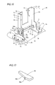
- the present invention is not restricted to this but a contact portion 95a and an inclined portion 95b may alternatively be provided on a first side surface of each stop member 95 for controlling pressing force for pressing a liquid crystal display portion support member 2 and a corresponding base support member 3 with a corresponding plate spring 6 and the inclined portion 95b of the stop member 95 as in a third modification of the aforementioned embodiment shown in Fig. 17.
Landscapes
- Engineering & Computer Science (AREA)
- General Engineering & Computer Science (AREA)
- Mechanical Engineering (AREA)
- Devices For Indicating Variable Information By Combining Individual Elements (AREA)
Abstract
Description
- The present invention relates to a display support mechanism, and more particularly, it relates to a display support mechanism capable of supporting a display screen in a state inclined by a prescribed angle.
- A display support mechanism capable of supporting a display screen in a state inclined by a prescribed angle is known in general, as disclosed in
Japanese Patent Laying-Open No. 2000-200048 Japanese Utility Model registration Nos. 3106183 3111702 Japanese Patent Laying-Open No. 2000-200048 - In the structure employing the round shaft as the axis of rotation for inclining the display screen by a prescribed angle disclosed in each of the patent documents such as the aforementioned
Japanese Patent Laying-Open No. 2000-200048 - The present invention has been proposed preferably in order to solve the aforementioned problem, and preferably an object of the present invention is to provide a display support mechanism capable of inclining a display screen by a prescribed angle without employing a round shaft as an axis of rotation.
- A display support mechanism according to a first aspect of the present invention comprises a support shaft provided in the form of a plate, a display screen support member, having a first hole receiving the platelike support shaft, provided on the side of a display screen and a base support member, having a second hole receiving the platelike support shaft, provided on the side of a base, and at least either the first hole or the second hole receiving the platelike support shaft is provided in the form of a sector while the display screen support member is rotatable about the platelike support shaft serving as an axis of rotation in the angular range of the sector.
- As hereinabove described, the display support mechanism according to the first aspect is provided with the platelike support shaft and the display screen support member is rendered rotatable about the platelike support shaft serving as the axis of rotation, so that the platelike support shaft can be employed as the axis of rotation. Thus, the display screen can be inclined by a prescribed angle without employing a round shaft as the axis of rotation. In this case, the platelike support shaft is so easily borable or shapable that no complicated working of the axis of rotation is required dissimilarly to a case of performing grooving or the like along the outer peripheral surface of a round shaft. Further, at least either the first hole or the second hole receiving the platelike support shaft is provided in the form of the sector while the display screen support member is rendered rotatable about the platelike support shaft serving as the axis of rotation in the angular range of the sector, whereby the rotatable angular range of the display screen support member can be regulated through the sectoral first or second hole without separately providing a member for regulating the angular range.
- In the aforementioned display support mechanism according to the first aspect, either the first hole or the second hole is preferably provided in the form of the sector while either the second hole or the first hole is preferably provided in the form of a rectangle for regulating rotation of the platelike support shaft. According to this structure, the platelike support shaft remains unsliding with respect to the display screen support member when the first hole thereof is provided in the form of a rectangle and remains unsliding with respect to the base support member when the second hole thereof is provided in the form of a rectangle, to be inhibited from abrasion resulting from sliding.
- In the aforementioned display support mechanism according to the first aspect, the bottom of the sector preferably receives the vertical load of the display screen through the display screen support member. According to this structure, the display screen support member can be easily rotated about the bottom of the sector.
- In this case, the length of the bottom is preferably substantially equalized to the thickness of the support shaft. According to this structure, the support shaft can be inhibited from positionally deviating from the bottom of the sector when the display screen support member is rotated about the bottom of the sector. Thus, rotation of the display screen support member can be stabilized.
- In the aforementioned structure having the bottom of the sector receiving the vertical load of the display screen through the display screen support member, the radial length of the sector is preferably larger than the length of a side of the support shaft corresponding to the radial width of the sector when at least either the first hole or the second hole is provided in the form of the sector. According to this structure, the support shaft can be inhibited from coming into contact with an arcuate side of the sector when rotated about the bottom of the sector, whereby rotation of the display screen support member can be stabilized.
- The aforementioned display support mechanism according to the first aspect preferably further comprises a spring member for pressing the display screen support member and the base support member to be rotatable about the platelike support shaft serving as the axis of rotation and a stop member for inhibiting the platelike support shaft from coming off the display screen support member and the base support member through the pressing force of the spring member. According to this structure, the display screen support member (display screen) can be supported in a state inclined by a prescribed angle with respect to the base support member (base) through the pressing force of the spring member. Thus, the operation for inclining the display screen support member (display screen) can be inhibited from complication dissimilarly to a case of fixing the display screen to the base by tightening a screw while inclining the display screen by a prescribed angle. Further, the stop member can easily hold a state of pressing the display screen support member and the base support member with the spring member.
- In this case, the spring member may include a plate spring.
- In the aforementioned structure comprising the stop member, the display support mechanism preferably further comprises a plate member inserted into the platelike support shaft and arranged between the display screen support member or the base support member and the stop member. According to this structure, the stop member remains unsliding with respect to the display screen support member or the base support member, to be inhibited from abrasion.
- In the aforementioned structure of the display support mechanism comprising the spring member and the stop member, the stop member is preferably provided in the form of a plate and receives the pressing force of the spring member on an end surface in a direction perpendicular to the thickness direction. According to this structure, the stop member can receive the pressing force of the spring member with the strong end surface in the direction perpendicular to the thickness direction, to be inhibited from bending resulting from the pressing force of the spring member.
- In the aforementioned structure of the display support mechanism comprising the spring member and the stop member, the stop member can preferably control the pressing force of the spring member pressing the display screen support member and the base support member against each other. According to this structure, the force necessary for rotating the display screen support member (display screen) with respect to the base support member (base) against the pressing force of the spring member can be easily controlled.
- The aforementioned display support mechanism according to the first aspect preferably further comprises a friction member for increasing frictional force between the display screen support member and the base support member. According to this structure, the force necessary for rotating the display screen support member (display screen) with respect to the base support member (base) can be increased, thereby inhibiting the display screen from moving with respect to the base through weak force.
- In this case, the friction member is preferably arranged to annularly enclose the support shaft. According to this structure, frictional force can be applied between the display screen support member and the base support member to be along the rotational direction around the support shaft serving as the center of rotation. Thus, rotation of the display screen support member can be stabilized with respect to the base support member.
- In the aforementioned display support mechanism according to the first aspect, the support shaft is preferably made of sheet metal. According to this structure, the support shaft can easily support the heavy display screen. Further, the support shaft of sheet metal, easily borable or shapable by press working, can be easily worked.
- A display support mechanism according to a second aspect of the present invention comprises a display screen support member provided on the side of a display screen and a base support member provided on the side of a base, and further comprises a support shaft provided in the form of a plate, a spring member for pressing the display screen support member and the base support member to be rotatable about the platelike support shaft serving as an axis of rotation, a stop member for inhibiting the platelike support shaft from coming off the display screen support member and the base support member through the pressing force of the spring member, a plate member inserted into the platelike support shaft and arranged between the display screen support member and the stop member and a friction member for increasing frictional force between the display screen support member and the base support member, while the display screen support member includes a first hole provided in the form of a sector for receiving the platelike support shaft and is rotatable about the platelike support shaft serving as an axis of rotation in the angular range of the sector, the base support member includes a second hole, receiving the platelike support shaft, provided in the form of a rectangle for regulating rotation of the platelike support shaft, the bottom of the sector receives the vertical load of the display screen through the display screen support member, and the stop member is provided in the form of a plate, receives the pressing force of the spring member on an end surface in a direction perpendicular to the thickness direction and can control the pressing force of the spring member pressing the display screen support member and the base support member against each other.
- As hereinabove described, the display support mechanism according to the second aspect is provided with the platelike support shaft and the display screen support member is rendered rotatable about the platelike support shaft serving as the axis of rotation, so that the platelike support shaft can be employed as the axis of rotation. Thus, the display screen can be inclined by a prescribed angle without employing a round shaft as the axis of rotation. In this case, the platelike support shaft is so easily borable or shapable that no complicated working of the axis of rotation is required dissimilarly to a case of performing grooving or the like along the outer peripheral surface of a round shaft. Further, the first hole of the display screen support member receiving the platelike support shaft is provided in the form of the sector while the display screen support member is rendered rotatable about the platelike support shaft serving as the axis of rotation in the angular range of the sector, whereby the rotatable angular range of the display screen support member can be regulated through the sectoral first hole without separately providing a member for regulating the angular range. In addition, the first hole of the display screen support member is provided in the form of the sector while the second hole of the base support member is provided in the form of the rectangle for regulating rotation of the platelike support shaft, whereby the platelike support shaft remains unsliding with respect to the base support member, to be inhibited from abrasion resulting from sliding. Further, the bottom of the sector receives the vertical load of the display screen through the display screen support member, whereby the display screen support member can be easily rotated about the bottom of the sector. Further, the spring member is provided for pressing the display screen support member and the base support member to be rotatable about the platelike support shaft serving as the axis of rotation, whereby the display screen support member (display screen) can be supported in a state inclined by a prescribed angle with respect to the base support member (base) through the pressing force of the spring member. Thus, the operation for inclining the display screen support member (display screen) can be inhibited from complication dissimilarly to a case of fixing the display screen to the base by tightening a screw while inclining the display screen by a prescribed angle.
- According to the second aspect, further, the display support mechanism is provided with the stop member for inhibiting the platelike support shaft from coming off the display screen support member and the base support member, so that the stop member can easily hold a state of pressing the display screen support member and the base support member with the spring member. The display support mechanism is further provided with the plate member inserted into the platelike support shaft and arranged between the display screen support member and the stop member, whereby the stop member remains unsliding with respect to the display screen support member, to be inhibited from abrasion. Further, the stop member is provided in the form of the plate and receives the pressing force of the spring member on the end surface in the direction perpendicular to the thickness direction, whereby the stop member can receive the pressing force of the spring member with the strong end surface in the direction perpendicular to the thickness direction, to be inhibited from bending resulting from the pressing force of the spring member. In addition, the stop member can control the pressing force of the spring member pressing the display screen support member and the base support member against each other, whereby the force necessary for rotating the display screen support member (display screen) with respect to the base support member (base) against the pressing force of the spring member can be easily controlled. Further, the display support mechanism is provided with the friction member for increasing the frictional force between the display screen support member and the base support member so that the force necessary for rotating the display screen support member (display screen) with respect to the base support member (base) can be increased, thereby inhibiting the display screen from moving with respect to the base through weak force.
- In the aforementioned display support mechanism according to the second aspect, the length of the bottom is preferably substantially equalized to the thickness of the support shaft. According to this structure, the support shaft can be inhibited from positionally deviating from the bottom of the sector when the display screen support member is rotated about the bottom of the sector. Thus, rotation of the display screen support member can be stabilized.
- In the aforementioned display support mechanism according to the second aspect, the radial length of the sectoral first hole is preferably larger than the length of a side of the support shaft corresponding to the radial width of the first hole. According to this structure, the support shaft can be inhibited from coming into contact with an arcuate side of the first hole when rotated about the bottom of the first hole, whereby rotation of the display screen support member can be stabilized.
- In the aforementioned display support mechanism according to the second aspect, the spring member may include a plate spring.
- In the aforementioned display support mechanism according to the second aspect, the friction member is preferably arranged to annularly enclose the support shaft. According to this structure, frictional force can be applied between the display screen support member and the base support member to be along the rotational direction around the support shaft serving as the center of rotation. Thus, rotation of the display screen support member can be stabilized with respect to the base support member.
- In the aforementioned display support mechanism according to the second aspect, the support shaft is preferably made of sheet metal. According to this structure, the support shaft can easily support the heavy display screen. Further, the support shaft of sheet metal, easily borable or shapable by press working, can be easily worked.
- The foregoing and other objects, features, aspects and advantages of the present invention will become more apparent from the following detailed description of the present invention when taken in conjunction with the accompanying drawings.
- IN THE DRAWINGS:
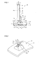
- Fig. 1 is a side elevational view showing the overall structure of a liquid crystal display provided with a display support mechanism according to an embodiment of the present invention;
- Fig. 2 is a perspective view of the display support mechanism according to the embodiment shown in Fig. 1, from which a liquid crystal display portion is removed;
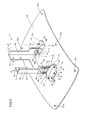
- Fig. 3 is a perspective view showing the overall structure of the display support mechanism according to the embodiment shown in Fig. 1;
- Fig. 4 is an exploded perspective view showing the overall structure of the display support mechanism according to the embodiment shown in Fig. 3;
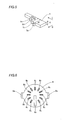
- Fig. 5 is a perspective view showing a stop member of the display support mechanism according to the embodiment shown in Fig. 3;
- Fig. 6 is a plan view showing a pressure-contact plate of the display support mechanism according to the embodiment shown in Fig. 3;
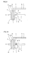
- Fig. 7 partially illustrates the display support mechanism as viewed along arrow E in Fig. 3;
- Fig. 8 is a sectional view taken along the line 100-100 in Fig. 3;
- Figs. 9 and 10 partially illustrate the display support mechanism as viewed along arrow F in Fig. 3;
- Fig. 11 is a sectional view taken along the line 200-200 in Fig. 3;
- Figs. 12 and 13 are sectional views for illustrating rotating operations of the display support mechanism according to the embodiment shown in Fig. 3;
- Fig. 14 is a side elevational view showing the overall structure of a liquid crystal display provided with a display support mechanism according to a first modification of the embodiment shown in Fig. 1;
- Fig. 15 is an exploded perspective view showing the overall structure of the display support mechanism according to the first modification shown in Fig. 14;
- Fig. 16 is a perspective view showing the overall structure of a display support mechanism according to a second modification of the embodiment shown in Fig. 1; and
- Fig. 17 is a perspective view showing a stop member of a display support mechanism according to a third modification of the embodiment shown in Fig. 5.
- An embodiment of the present invention is now described with reference to the drawings.
- First, the structure of a
display support mechanism 1 according to the embodiment of the present invention is described with reference to Figs. 1 to 11. - The
display support mechanism 1 according to the embodiment of the present invention is provided for supporting a liquidcrystal display portion 40 of aliquid crystal display 30, as shown in Fig. 1. Thisdisplay support mechanism 1 is mounted on abase 50. Thedisplay support mechanism 1 supports the liquidcrystal display portion 40 to be rotatable in directions A and B with respect to thebase 50, as shown in Figs. 1 and 2. Thedisplay support mechanism 1 is enabled to support the liquidcrystal display portion 40 in a state inclined by a prescribed angle with respect to thebase 50. - As shown in Figs. 3 and 4, the
display support mechanism 1 comprises a liquid crystal displayportion support member 2, a pair ofbase support members 3,platelike support shafts 4 of sheet metal, stopmembers 5 of sheet metal, plate springs 6,friction members 7 and pressure-contact plates 8 of sheet metal. - According to this embodiment, the liquid crystal display
portion support member 2 includes adisplay mounting portion 2a and a pair ofrotational portions 2b, as shown in Figs. 3 and 4. Thedisplay mounting portion 2a of the liquid crystal displayportion support member 2 is provided with fourscrew receiving holes 2c. The pair ofrotational portions 2b of the liquid crystal displayportion support member 2 are so provided as to extend from both side ends of thedisplay mounting portion 2a perpendicularly to the surface thereof respectively. As shown in Fig. 4,sectoral holes 2d and pairs ofarcuate holes 2e are provided in the vicinity of the lower ends of the pair ofrotational portions 2b respectively. The liquid crystal displayportion support member 2 is an example of the "display screen support member" in the present invention. Theholes 2d are examples of the "first hole" in the present invention. - The
sectoral holes 2d are provided for receiving theplatelike support shafts 4, as shown in Figs. 4 and 8. Eachsectoral hole 2d has a central angle α of about 60° and is so arranged as to direct abottom portion 2f thereof upward, as shown in Fig. 11. The length L4 of thebottom portions 2f of thesectoral holes 2d is substantially identical to the thickness T1 (see Fig. 4) of thesupport shafts 4, as described later. Thus, thebottom portions 2f of thesectoral holes 2d receive the vertical load of the liquidcrystal display portion 40 through the liquid crystal displayportion support member 2. The liquid crystal displayportion support member 2 is rendered rotatable about thebottom portions 2f of thesectoral holes 2d supported by theplatelike support shafts 4 in a sectoral angular range (about 60° according to this embodiment). In other words, theplatelike support shafts 4 function as the axes of rotation of the liquid crystal displayportion support member 2. The radial length L5 of eachhole 2d is larger than the width W1 of the correspondingplatelike support shaft 4, as shown in Fig. 11. - Each pair of
arcuate holes 2e are provided for receivingengaging sections 8a of the corresponding pressure-contact plate 8 as described later, as shown in Fig. 11. The pair ofarcuate holes 2e are arranged on a circle around thebottom portion 2f of thesectoral hole 2d. - According to this embodiment, the pair of
base support members 3 includebase mounting portions 3a and rotationalportion mounting portions 3b respectively, as shown in Figs. 3 and 4. Fourscrew mounting holes 3c are provided on thebase mounting portion 3a of eachbase support member 3. The rotationalportion mounting portions 3b of thebase support members 3 are so provided as to vertically extend upward from first ends of the surfaces of thebase mounting portions 3a. These rotationalportion mounting portions 3b are provided withrectangular holes 3d and pairs ofarcuate holes 3e smaller in arcuate length than the pairs ofarcuate holes 2e of thedisplay mounting portions 2b of the liquid crystal displayportion support member 2. Theholes 3d are examples of the "second hole" in the present invention. - The
rectangular holes 3d are provided for receiving theplatelike support shafts 4, as shown in Figs. 4 and 8. The short-directional length L1 of therectangular holes 3d is substantially identical to the thickness T1 (see Fig. 4) of thesupport shafts 4, as described later. Thus, therectangular holes 3d have functions of regulating rotation of thesupport shafts 4. The pairs ofarcuate holes 3e are provided for engaging with the engagingsections 8a of the pressure-contact plates 8, as described later. Further, the pairs ofarcuate holes 3e are arranged on circles around the upper ends of therectangular holes 3d respectively. - According to this embodiment, the
platelike support shafts 4 of sheet metal include pairs ofcontact portions 4a andrectangular holes 4b respectively, as shown in Figs. 3 and 4. The pairs ofcontact portions 4a of thesupport shafts 4 are protrusively provided on rear ends of longitudinally extending side surfaces of thesupport shafts 4 respectively. Eachcontact portion 4a is provided for coming into contact with thecorresponding plate spring 6, as shown in Figs. 7 and 8. Therectangular hole 4b of eachsupport shaft 4 is provided for receiving thecorresponding stop member 5, as shown in Figs. 4 and 8. The short-directional length L2 of therectangular holes 4b is substantially identical to the thickness T2 (see Fig. 5) of thestop members 5, as described later. Theholes 4b have a longitudinal length L3. - According to this embodiment, each
stop member 5 of sheet metal is provided in the form of a plate and includes acontact portion 5a and engagingportions stop members 5 are provided for inhibiting theplatelike support shafts 4 from coming off thesectoral holes 2d of the liquid crystal displayportion support member 2 and therectangular holes 3d of thebase support member 3 through the pressing force of the plate springs 6. Thecontact portion 5a of eachstop member 5 is provided in a direction D (perpendicular to the thickness direction) perpendicular to an insertional direction C, as shown in Fig. 5. A portion of eachstop member 5 corresponding to thecontact portion 5a has a width W2 (see Fig. 5) larger than the longitudinal length L3 (see Fig. 4) of theholes 4b of thesupport shafts 4. Thiscontact portion 5a is provided for coming into contact with the surface of thecorresponding support shaft 4 thereby inhibiting thestop member 5 from coming off thehole 4b of thecorresponding support shaft 4 when inserted into thehole 4b. - The engaging
portions stop member 5 are enabled to receive and control the pressing force of thecorresponding plate spring 6 pressing the liquid crystal displayportion support member 2 and the correspondingbase support member 3. More specifically, the engagingportion 5b of eachstop member 5 is provided adjacently to thecontact portion 5a, as shown in Fig. 5. The engagingportion 5c of thestop member 5 is adjacent to the engagingportion 5b through astep 5d. A portion of thestop member 5 corresponding to the engagingportion 5b has a width W3 smaller than the width W2 of the portion corresponding to thecontact portion 5a as well as the longitudinal length L3 (see Fig. 4) of thehole 4b of thecorresponding support shaft 4. A portion of thestop member 5 corresponding to the engagingportion 5c has a width W4 smaller than the width W3 of the portion corresponding to the engagingportion 5b as well as the longitudinal length L3 (see Fig. 4) of thehole 4b of thecorresponding support shaft 4. When the engagingportion 5c is arranged in thehole 4b of thecorresponding support shaft 4 as shown in Fig. 10, therefore, the distance between the correspondingbase support member 3 and thecontact portion 4a of thesupport shaft 4 is increased by the length (= W3 - W4) of thestep 5d of thestop member 5 as compared with a case where the engagingportion 5b is arranged in thehole 4b of thecorresponding support shaft 4 as shown in Fig. 9. Thus, the pressing force of thecorresponding plate spring 6 pressing the liquid crystal displayportion support member 2 and the correspondingbase support member 3 can be reduced when the engagingportion 5c is arranged in thehole 4b of thecorresponding support shaft 4, as compared with the case where the engagingportion 5b is arranged in thehole 4b of thecorresponding support shaft 4. Theplate spring 6 presses the liquid crystal displayportion support member 2 and the correspondingbase support member 3 with such pressing force that the liquid crystal displayportion support member 2 is rotatable about thecorresponding support shaft 4 serving as an axis of rotation and supportable at a prescribed angle of inclination with respect to the correspondingbase support member 3. - According to this embodiment, the plate springs 6 are made of stainless steel and have
rectangular holes 6a, as shown in Figs. 3 and 4. These plate springs 6 have functions of pressing the liquid crystal displayportion support member 2 and thebase support members 3 to be rotatable about theplatelike support shafts 4 serving as axes of rotation. Therectangular holes 6a of the plate springs 6 are provided for receiving thesupport shafts 4, as shown in Figs. 4 and 8. The plate springs 6 are examples of the "spring member" in the present invention. - According to this embodiment, the
friction members 7 are made of felt or vinyl chloride and provided in the form of circles, as shown in Fig. 4. Thesefriction members 7 are so arranged as to annularly enclose thesupport shafts 4, as shown in Figs. 4 and 8. Further, thefriction members 7 are provided withcircular holes 7a, to be capable of receiving thesupport shafts 4. Thefriction members 7 are provided for increasing the frictional force between the liquid crystal displayportion support member 2 and thebase support members 3. - According to this embodiment, the pressure-
contact plates 8 of sheet metal are provided in the form of circles and include pairs of engagingsections 8a,rectangular holes 8b and a plurality of projectingportions 8c, as shown in Figs. 3, 4 and 6. These pressure-contact plates 8 are arranged between the liquid crystal displayportion support member 2 and thestop members 5. The pairs of engagingsections 8a of the pressure-contact plates 8 are so provided as to perpendicularly extend from ends of the surfaces of the pressure-contact plates 8. Therectangular holes 8b of the pressure-contact plates 8 are provided for receiving thesupport shafts 4, as shown in Figs. 4 and 8. The short-directional length of therectangular holes 8b is substantially identical to the thickness T1 (see Fig. 4) of thesupport shafts 4, while the longitudinal length of therectangular holes 8b is substantially identical to the width W1 (see Fig. 4) of thesupport shafts 4. The plurality of projectingportions 8c of the pressure-contact plates 8 are provided on the surfaces having the protruding engagingsections 8a for increasing the frictional force between the liquid crystal displayportion support member 2 and the pressure-contact plates 8. The pressure-contact plates 8 are examples of the "plate member" in the present invention. - The liquid
crystal display portion 40 includes aliquid crystal module 41 including aliquid crystal screen 41a, afront cabinet 42 and arear cabinet 43, as shown in Fig. 1. Theliquid crystal module 41 of the liquidcrystal display portion 40 is mounted on the liquid crystal displayportion support member 2 byfastening screws 60 to screw mounting holes (not shown) through thescrew receiving holes 2c of the liquid crystal displayportion support member 2. Therear cabinet 43 is provided with anotch 43a for receiving the liquid crystal displayportion support member 2. The liquidcrystal display portion 40 is an example of the "display screen" in the present invention. - The
base 50 includes abase body 51, acover member 52 andsupport legs 53, as shown in Figs. 1 to 3. Thebase support members 3 are mounted on thebase body 51 of the base 50 byfastening screws 61 to thescrew mounting holes 3c of thebase support members 3 through screw receiving holes (not shown) of thebase body 51 from the side of the bottom surface. Thecover member 52 of thebase 50 is mounted on thebase body 51 by fastening screws (not shown) to screw mounting holes (not shown) of thecover member 52 throughscrew receiving holes 51a of thebase body 51 from the side of the bottom surface. Thecover member 52 is provided with anotch 52a for receiving the liquid crystal displayportion support member 2. Thesupport legs 53 are mounted on the bottom surface of thebase body 51. - Rotating operations of the
display support mechanism 1 according to this embodiment are now described with reference to Figs. 1 and 11 to 13. - In order to incline the liquid crystal display
portion support member 2 frontward, the liquid crystal display portion 40 (see Fig. 1) supported by the liquid crystal displayportion support member 2 is grasped and pressed in the direction A from the state upright with respect to thebase support members 3 as shown in Fig. 11. Thus, the liquid crystal displayportion support member 2 is rotated in the direction A about thebottom portion 2f of eachsectoral hole 2d, as shown in Fig. 12. The liquid crystal displayportion support member 2 is pressed and rotated in the direction A up to a prescribed angle of inclination, to be supported by thebase support members 3 at this angle of inclination. According to this embodiment, the liquid crystal displayportion support member 2 is rotatable (inclinable) up to an angle of inclination of 30° in the direction A so that eachsupport shaft 4 comes into contact with a first end surface of the correspondingsectoral hole 2d, as shown in Fig. 12. - In order to incline the liquid crystal display
portion support member 2 backward, on the other hand, the liquid crystal display portion 40 (see Fig. 1) supported by the liquid crystal displayportion support member 2 is grasped and pressed in the direction B from the state upright with respect to thebase support members 3 as shown in Fig. 11. Thus, the liquid crystal displayportion support member 2 is rotated in the direction B about thebottom portion 2f of eachsectoral hole 2d, as shown in Fig. 13. The liquid crystal displayportion support member 2 is pressed and rotated in the direction B up to a prescribed angle of inclination, to be supported by thebase support members 3 at this angle of inclination. According to this embodiment, the liquid crystal displayportion support member 2 is rotatable (inclinable) up to an angle of inclination of 30° in the direction B so that eachsupport shaft 4 comes into contact with a second end surface of the correspondingsectoral hole 2d, as shown in Fig. 13. - According to this embodiment, as hereinabove described, the
display support mechanism 1 is provided with theplatelike support shafts 4 of sheet metal and the liquid crystal displayportion support member 2 is rendered rotatable about theplatelike support shafts 4 serving as the axes of rotation, whereby theplatelike support shafts 4 can be employed as the axes of rotation. Thus, the liquidcrystal display portion 40 can be inclined by a prescribed angle without employing round shafts as axes of rotation. In this case, theplatelike support shafts 4 of sheet metal are so easily borable or shapable by press working that no complicated working of the axes of rotation is required dissimilarly to a case of performing grooving or the like along the outer peripheral surfaces of round shafts. Further, theholes 2d of the liquid crystal displayportion support member 2 receiving theplatelike support shafts 4 are provided in the form of sectors while the displayportion support member 2 is rendered rotatable about theplatelike support shafts 4 serving as the axes of rotation in the angular range (about 60° according to the embodiment) of the sectors, whereby the rotatable angular range of the displayportion support member 2 can be regulated through thesectoral holes 2d without separately providing members for regulating the angular range. - According to this embodiment, the
holes 2d of the liquid crystal displayportion support member 2 are provided in the form of sectors while theholes 3d of thebase support members 3 are provided in the form of rectangles for regulating rotation of thesupport shafts 4 so that theplatelike support shafts 4 remain unsliding with respect to thebase support members 3, to be inhibited from abrasion resulting from sliding. - According to this embodiment, the
bottom portions 2f of thesectoral holes 2d receive the vertical load of the liquidcrystal display portion 40 through the liquid crystal displayportion support member 2, whereby the liquid crystal displayportion support member 2 can be easily rotated about thebottom portions 2f of thesectoral holes 2d. - According to this embodiment, the
display support mechanism 1 is provided with the plate springs 6 for pressing the liquid crystal displayportion support member 2 and thebase support members 3 to be rotatable about theplatelike support shafts 4 serving as the axes of rotation, thereby supporting the liquid crystal display portion support member 2 (liquid crystal display portion 40) in a state inclined by a prescribed angle with respect to the base support members 3 (base 50) through the pressing force of the plate springs 6. Thus, the operation for inclining the display portion support member 2 (liquid crystal display screen 40) can be inhibited from complication dissimilarly to a case of fixing thedisplay screen 40 to thebase 50 by tightening screws while inclining thedisplay screen 40 by a prescribed angle. - According to this embodiment, the
display support mechanism 1 is provided with thestop members 5 for inhibiting theplatelike support shafts 4 from coming off the liquid crystal displayportion support member 2 and thebase support members 3 through the pressing force of the plate springs 5, whereby thestop members 5 can easily hold the state of the plate springs 6 pressing the liquid crystal displayportion support member 2 and thebase support members 3. - According to this embodiment, the
display support mechanism 1 is provided with the pressure-contact plates 8 inserted into theplatelike support shafts 4 and arranged between the liquid crystal displayportion support member 2 and thestop members 5 so that thestop members 5 remain unsliding with respect to the liquid crystal displayportion support member 2, to be inhibited from abrasion. - According to this embodiment, the
stop members 5 are provided in the form of plates and formed to receive the pressing force of the plate springs 5 on the strong end surfaces in the direction D perpendicular to the thickness direction, to be inhibited from bending resulting from the pressing force of the plate springs 6. - According to this embodiment, the
stop members 5 are enabled to control the pressing force of the plate springs 6 pressing the liquid crystal displayportion support member 2 and thebase support members 3 against each other, whereby the force necessary for rotating the liquid crystal display portion support member 2 (liquid crystal display portion 40) with respect to the base support members 3 (base 3) against the pressing force of the plate springs 6 can be easily controlled. - According to this embodiment, the
display support mechanism 1 is provided with thefriction members 7 for increasing the frictional force between the liquid crystal displayportion support member 2 and thebase support members 3 so that the force necessary for rotating the liquid crystal display portion support member 2 (liquid crystal display portion 40) with respect to the base support members 3 (base 50) can be increased, thereby inhibiting the liquidcrystal display portion 40 from moving with respect to the base 50 through weak force. - According to this embodiment, the length L4 of the
bottom portions 2f is substantially equalized to the thickness T1 of thesupport shafts 4, whereby thesupport shafts 4 can be inhibited from positionally deviating from thebottom portions 2f of thesectoral holes 2d when the liquid crystal displayportion support member 2 is rotated about thebottom portions 2f of thesectoral holes 2d. Thus, the operation of rotating the liquid crystal displayportion support member 2 can be stabilized. - According to this embodiment, the radial length L5 of the
sectoral holes 2d is rendered larger than the width W1 of the sides of thesupport shafts 4 corresponding to the length L5 of theholes 2d so that thesupport shafts 4 can be inhibited from coming into contact with arcuate sides of theholes 2d when rotated about thebottom portions 2f of theholes 2d, whereby the operation of rotating the liquid crystal displayportion support member 2 can be stabilized. - Although the present invention has been described and illustrated in detail, it is clearly understood that the same is by way of illustration and example only and is not to be taken by way of limitation, the spirit and scope of the present invention being limited only by the terms of the appended claims as interpreted by the description and drawings.
- For example, while the display support mechanism is provided on the liquid crystal display in the aforementioned embodiment, the present invention is not restricted to this but the display support mechanism may alternatively be provided on a display such as an organic EL display other than the liquid crystal display.
- While the holes of the base support members are provided in the form of rectangles, the holes of the liquid crystal display portion support member are provided in the form of sectors and the bottom portions of the sectors are directed upward in the aforementioned embodiment, the present invention is not restricted to this but the holes of the liquid crystal display portion support member may alternatively be provided in the form of rectangles, the holes of the base support members may alternatively be provided in the form of sectors, and the bottom portions of the sectors may alternatively be directed downward. When the liquid crystal display portion support member is rotated with respect to the base support members in this case, the support shafts inserted into the rectangular holes of the liquid crystal display portion support member are rotated integrally with the liquid crystal display portion support member about the bottom portions of the sectoral holes of the base support members.
- While the center of rotation of the liquid crystal display
portion support member 2 is provided in the base 50 in the aforementioned embodiment, the present invention is not restricted to this but the center of rotation of a liquid crystal displayportion support member 72 may be provided in a liquidcrystal display portion 40 as in adisplay support mechanism 70 according to a first modification of the aforementioned embodiment shown in Figs. 14 and 15. More specifically, thedisplay support mechanism 70 according to the first modification comprises the liquid crystal displayportion support member 72 arranged in the liquidcrystal display portion 40 andbase support members 73 protruding upward from anotch 52a of thebase 50. The liquid crystal displayportion support member 72 is constituted of adisplay mounting portion 72a formed withscrew receiving holes 72c and a pair ofrotational portions 72b formed withsectoral holes 72d havingbottom portions 72f andarcuate holes 72e respectively. Thebase support members 73 are constituted ofbase mounting portions 73a formed withscrew receiving holes 73c and rotationalportion mounting portions 73b formed withrectangular holes 73d andarcuate holes 73e. In this case, the rotationalportion mounting portions 73b of thebase support members 73 are so provided as to extend upward through thenotch 52a while therectangular holes 73d and thearcuate holes 73e are provided in the vicinity of the upper ends so that theseholes crystal display portion 40. - While the
support shafts 4, thestop members 5, the plate springs 6, thefriction members 7 and the pressure-contact plates 8 are provided for the pair ofbase support members 3 and the pair ofrotational portions 2b of the liquid crystal displayportion support member 2 respectively in the aforementioned embodiment, the present invention is not restricted to this but asupport shaft 84 having acontact portion 84a, astop member 5, aplate spring 6, afriction member 7 and a pressure-contact plate 8 may alternatively be provided only for the first one of a pair ofbase support members 3 and the first one of a pair ofrotational portions 2b of a liquid crystal displayportion support member 2 as in adisplay support mechanism 80 according to a second modification of the aforementioned embodiment shown in Fig. 16. In this case, thesupport shaft 84 is so formed as to extend toward and enter arectangular hole 3d of the secondbase support member 3 and asectoral hole 2d of a secondrotational portion 2b of the liquid crystal displayportion support member 2. - While the
stop members 5 are provided with the engagingportions portion support member 2 and thebase support members 3 with the plate springs 6 and thestop members 5 in the aforementioned embodiment, the present invention is not restricted to this but acontact portion 95a and aninclined portion 95b may alternatively be provided on a first side surface of eachstop member 95 for controlling pressing force for pressing a liquid crystal displayportion support member 2 and a correspondingbase support member 3 with acorresponding plate spring 6 and theinclined portion 95b of thestop member 95 as in a third modification of the aforementioned embodiment shown in Fig. 17.
Claims (19)
- A display support mechanism comprising:a support shaft (4) provided in the form of a plate;a display screen support member (2), having a first hole (2d) receiving said platelike support shaft, provided on the side of a display screen (40); anda base support member (3), having a second hole (3d) receiving said platelike support shaft, provided on the side of a base (50), whereinat least either said first hole or said second hole receiving said platelike support shaft is provided in the form of a sector while said display screen support member is rotatable about said platelike support shaft serving as an axis of rotation in the angular range of said sector.
- The display support mechanism according to claim 1, wherein
either said first hole or said second hole is provided in the form of said sector while either said second hole or said first hole is provided in the form of a rectangle for regulating rotation of said platelike support shaft. - The display support mechanism according to claim 1, wherein
the bottom (2f) of said sector receives the vertical load of said display screen through said display screen support member. - The display support mechanism according to claim 3, wherein
the length of said bottom is substantially equalized to the thickness of said support shaft. - The display support mechanism according to claim 3, wherein
the radial length of said sector is larger than the length of a side of said support shaft corresponding to the radial width of said sector when at least either said first hole or said second hole is provided in the form of said sector. - The display support mechanism according to claim 1, further comprising:a spring member (6) for pressing said display screen support member and said base support member to be rotatable about said platelike support shaft serving as an axis of rotation, anda stop member (5) for inhibiting said platelike support shaft from coming off said display screen support member and said base support member through the pressing force of said spring member.
- The display support mechanism according to claim 6, wherein
said spring member includes a plate spring. - The display support mechanism according to claim 6, further comprising a plate member (8) inserted into said platelike support shaft and arranged between said display screen support member or said base support member and said stop member.
- The display support mechanism according to claim 6, wherein
said stop member is provided in the form of a plate and receives the pressing force of said spring member on an end surface in a direction perpendicular to the thickness direction. - The display support mechanism according to claim 6, wherein
said stop member can control the pressing force of said spring member pressing said display screen support member and said base support member against each other. - The display support mechanism according to claim 1, further comprising a friction member (7) for increasing frictional force between said display screen support member and said base support member.
- The display support mechanism according to claim 11, wherein
said friction member is arranged to annularly enclose said support shaft. - The display support mechanism according to claim 1, wherein
said support shaft is made of sheet metal. - A display support mechanism (1) comprising a display screen support member (2) provided on the side of a display screen (40) and a base support member (3) provided on the side of a base (50),
further comprising a support shaft (4) provided in the form of a plate, a spring member (6) for pressing said display screen support member and said base support member to be rotatable about said platelike support shaft serving as an axis of rotation, a stop member (5) for inhibiting said platelike support shaft from coming off said display screen support member and said base support member through the pressing force of said spring member, a plate member (8) inserted into said platelike support shaft and arranged between said display screen support member and said stop member and a friction member (7) for increasing frictional force between said display screen support member and said base support member, wherein
said display screen support member includes a first hole (2d) provided in the form of a sector for receiving said platelike support shaft and is rotatable about said platelike support shaft serving as an axis of rotation in the angular range of said sector,
said base support member includes a second hole (3d), receiving said platelike support shaft, provided in the form of a rectangle for regulating rotation of said platelike support shaft,
the bottom (2f) of said sector receives the vertical load of said display screen through said display screen support member, and
said stop member is provided in the form of a plate, receives the pressing force of said spring member on an end surface in a direction perpendicular to the thickness direction and can control the pressing force of said spring member pressing said display screen support member and said base support member against each other. - The display support mechanism according to claim 14, wherein
the length of said bottom is substantially equalized to the thickness of said support shaft. - The display support mechanism according to claim 14, wherein
the radial length of said sectoral first hole is larger than the length of a side of said support shaft corresponding to the radial width of said first hole. - The display support mechanism according to claim 14, wherein
said spring member includes a plate spring. - The display support mechanism according to claim 14, wherein
said friction member is arranged to annularly enclose said support shaft. - The display support mechanism according to claim 14, wherein
said support shaft is made of sheet metal.
Priority Applications (1)
| Application Number | Priority Date | Filing Date | Title |
|---|---|---|---|
| PL07250259T PL1811223T3 (en) | 2006-01-23 | 2007-01-23 | Display support mechanism |
Applications Claiming Priority (1)
| Application Number | Priority Date | Filing Date | Title |
|---|---|---|---|
| JP2006013305A JP2007193245A (en) | 2006-01-23 | 2006-01-23 | Display screen supporting mechanism |
Publications (3)
| Publication Number | Publication Date |
|---|---|
| EP1811223A2 true EP1811223A2 (en) | 2007-07-25 |
| EP1811223A3 EP1811223A3 (en) | 2009-08-26 |
| EP1811223B1 EP1811223B1 (en) | 2012-03-07 |
Family
ID=37966399
Family Applications (1)
| Application Number | Title | Priority Date | Filing Date |
|---|---|---|---|
| EP07250259A Not-in-force EP1811223B1 (en) | 2006-01-23 | 2007-01-23 | Display support mechanism |
Country Status (5)
| Country | Link |
|---|---|
| US (1) | US8002223B2 (en) |
| EP (1) | EP1811223B1 (en) |
| JP (1) | JP2007193245A (en) |
| CN (1) | CN101009146B (en) |
| PL (1) | PL1811223T3 (en) |
Cited By (4)
| Publication number | Priority date | Publication date | Assignee | Title |
|---|---|---|---|---|
| EP2112421A3 (en) * | 2008-04-23 | 2009-12-30 | Funai Electric Co., Ltd. | Display screen support mechanism |
| EP1956282A3 (en) * | 2007-02-08 | 2010-11-03 | Funai Electric Co., Ltd. | Display screen turning apparatus |
| TWI413410B (en) * | 2008-11-14 | 2013-10-21 | Hon Hai Prec Ind Co Ltd | Adjustable module and adjustable assembly using the same |
| CN108877105A (en) * | 2018-08-29 | 2018-11-23 | 深圳怡化电脑股份有限公司 | A kind of self-aided terminal and its camera structure |
Families Citing this family (13)
| Publication number | Priority date | Publication date | Assignee | Title |
|---|---|---|---|---|
| TWI290278B (en) * | 2005-12-12 | 2007-11-21 | Hannspree Inc | Automatic anti-tip over mechanism for display |
| JP2007248542A (en) * | 2006-03-14 | 2007-09-27 | Funai Electric Co Ltd | Display screen support mechanism |
| JP4222410B2 (en) * | 2006-11-07 | 2009-02-12 | 船井電機株式会社 | Display screen turning device |
| US7934292B2 (en) * | 2007-01-04 | 2011-05-03 | Apple Inc. | Hinge mechanism |
| JP2009047921A (en) * | 2007-08-20 | 2009-03-05 | Sharp Corp | Display device |
| JP2009265218A (en) * | 2008-04-23 | 2009-11-12 | Funai Electric Co Ltd | Display device |
| JP4530075B2 (en) * | 2008-05-07 | 2010-08-25 | 船井電機株式会社 | Display screen turning device and television device |
| JP2009284131A (en) * | 2008-05-21 | 2009-12-03 | Funai Electric Co Ltd | Display apparatus and television apparatus |
| KR101470640B1 (en) * | 2008-07-14 | 2014-12-08 | 엘지전자 주식회사 | Display device |
| JP2010091903A (en) * | 2008-10-10 | 2010-04-22 | Funai Electric Co Ltd | Display screen turning apparatus |
| GB2477934A (en) * | 2010-02-17 | 2011-08-24 | Sony Espana Sa | Television stand with angle adjustment means |
| JP5017467B1 (en) | 2011-03-01 | 2012-09-05 | 株式会社東芝 | Video display device |
| JP5198640B2 (en) * | 2011-10-07 | 2013-05-15 | 株式会社東芝 | Television receiver and electronic device |
Citations (3)
| Publication number | Priority date | Publication date | Assignee | Title |
|---|---|---|---|---|
| JP2000200048A (en) | 2000-01-14 | 2000-07-18 | Nippon Avionics Co Ltd | Terminal device tilt mechanism |
| JP3106183U (en) | 2004-06-25 | 2004-12-16 | 船井電機株式会社 | Liquid crystal television and liquid crystal display |
| JP3111702U (en) | 2005-04-20 | 2005-07-28 | 船井電機株式会社 | Liquid crystal display |
Family Cites Families (48)
| Publication number | Priority date | Publication date | Assignee | Title |
|---|---|---|---|---|
| US553650A (en) * | 1896-01-28 | Look chain | ||
| US2498557A (en) * | 1945-03-29 | 1950-02-21 | Lantz Alpha Perry | Means for pivotally supporting and bracing ironing boards |
| US2498558A (en) * | 1945-04-21 | 1950-02-21 | Lantz Alpha Perry | Pivotal mounting and brace for ironing boards |
| US3936026A (en) * | 1975-03-24 | 1976-02-03 | Ultronic Systems Corporation | Swivel base assembly |
| GB1515056A (en) * | 1975-09-08 | 1978-06-21 | Shikimi Y | Apparatus for mounting an object on an upright |
| US4226398A (en) * | 1979-01-15 | 1980-10-07 | Marquette Tool And Die Company | Furniture swivel |
| US4310136A (en) * | 1979-11-13 | 1982-01-12 | Quick-Set, Incorporated | Backlash-free swivel and tilt mounting |
| DE3700885A1 (en) * | 1986-09-29 | 1988-03-31 | Eberhard Tittel | CAR ROOF CARRIER WITH AT LEAST ONE SWIVELING HOLDING PART BETWEEN A USED POSITION AND A NON-USED POSITION |
| US4953259A (en) * | 1988-07-11 | 1990-09-04 | Prince Corporation | Armrest torque control |
| US4919383A (en) * | 1989-03-30 | 1990-04-24 | Trans World Marketing Corp. | Rotating display |
| EP0445635B1 (en) * | 1990-03-07 | 1995-08-16 | TOFUJI E.M.I. Co.,Ltd. | Opening/closing mechanism |
| US5022778A (en) * | 1990-11-02 | 1991-06-11 | Lu Sheng N | Pivot shaft |
| US5239731A (en) * | 1992-06-03 | 1993-08-31 | Lu Sheng N | Hinge device for casings |
| US5208944A (en) * | 1992-06-16 | 1993-05-11 | Lu Sheng N | Hinge device for casings |
| US5289616A (en) * | 1992-09-08 | 1994-03-01 | Yoshihiko Taniyama | Hinge with motion limiting mechanism |
| US5316373A (en) * | 1993-02-04 | 1994-05-31 | Voyager, Inc. | Seat arm rest |
| US5645308A (en) * | 1995-08-29 | 1997-07-08 | Prince Corporation | Sliding visor |
| JPH09196048A (en) * | 1996-01-18 | 1997-07-29 | Kato Electrical Mach Co Ltd | Tilt hinge |
| JPH1026128A (en) * | 1996-07-10 | 1998-01-27 | Kato Electrical Mach Co Ltd | Tilt hinge |
| US5812368A (en) * | 1997-06-04 | 1998-09-22 | Kuo Feng Corporation | Monitor viewing angle adjusting assembly having monitor mounted on two supporting arm assemblies via turning limit assemblies |
| US6018847A (en) * | 1998-07-02 | 2000-02-01 | Lu; Sheng-Nan | Hinge axle device for a LCD monitor |
| DE19833157A1 (en) * | 1998-07-23 | 2000-01-27 | Bosch Gmbh Robert | Holding fixture for vehicle gyro navigation instrument suitable for installation in a wide range of vehicles irrespective of orientation |
| KR100279633B1 (en) * | 1998-12-08 | 2001-02-01 | 구자홍 | 2-axis power rotating device and its control method |
| TW506549U (en) * | 1999-07-22 | 2002-10-11 | Kato Electric & Machinary Co | Slanted hinge |
| US6588609B1 (en) * | 2000-01-12 | 2003-07-08 | Kensington Technology Group, A Division Of Acco Brands, Inc. | Display device stand with rotatable storage |
| US6447065B1 (en) * | 2000-07-19 | 2002-09-10 | Sears Manufacturing Company | Adjustable swivel assembly for seat suspensions |
| JP3511506B2 (en) * | 2000-11-08 | 2004-03-29 | 富士通株式会社 | Display support device |
| US20020083554A1 (en) | 2001-01-03 | 2002-07-04 | Lu Sheng-Nan | Concealed retaining device for a pivot |
| KR100703160B1 (en) * | 2001-02-19 | 2007-04-05 | 삼성전자주식회사 | Display device |
| JP2002311845A (en) * | 2001-04-16 | 2002-10-25 | Fujitsu Ltd | Display device |
| US6671928B2 (en) * | 2001-05-23 | 2004-01-06 | Kuo-Cheng Huang | Hinge assembly for monitor |
| KR100727384B1 (en) * | 2001-09-11 | 2007-06-12 | 삼성전자주식회사 | Hinge device |
| GB2397336B (en) * | 2001-12-24 | 2005-02-02 | Lg Electronics Inc | Hinge assembly for flat panel display appliance |
| TW531019U (en) | 2001-12-31 | 2003-05-01 | Hinge Basestrong Co Ltd | Improved LCD seat |
| KR100770981B1 (en) * | 2002-10-30 | 2007-10-30 | 삼성전자주식회사 | Stand of display |
| US6757940B2 (en) * | 2002-11-18 | 2004-07-06 | Shin Zu Shing Co., Ltd. | Hinge for a notebook computer |
| US6813813B2 (en) * | 2003-01-06 | 2004-11-09 | Shin Zu Shing Co., Ltd. | Collapsible hinge bracket for a laptop computer |
| TW588818U (en) * | 2003-03-11 | 2004-05-21 | Top Victory Electronics Taiwan | Rotatable supporting station |
| US6779234B1 (en) * | 2003-04-14 | 2004-08-24 | Shin Zu Shing Co., Ltd. | Elastic hinge for a notebook computer |
| US6837469B2 (en) * | 2003-05-01 | 2005-01-04 | Wei Chung Wu | Structure of liquid crystal display (LCD) |
| US20050268431A1 (en) | 2004-05-19 | 2005-12-08 | Huan-Chen Lo | Support and angle adjustable device for monitors |
| TWM261941U (en) * | 2004-06-21 | 2005-04-11 | Quanta Comp Inc | Display swivel |
| JP3106184U (en) * | 2004-06-25 | 2004-12-16 | 船井電機株式会社 | Liquid crystal television and liquid crystal display |
| KR101063408B1 (en) * | 2004-10-11 | 2011-09-07 | 삼성전자주식회사 | Hinge Device and Electronic Device Having the Same |
| US7314203B2 (en) * | 2004-12-15 | 2008-01-01 | Chi Yau Yue | Base for vanity mirror or other small object with enhanced stability and rotational ability |
| KR100710078B1 (en) * | 2005-06-13 | 2007-04-23 | 삼성전자주식회사 | Monitor device |
| JP2007233232A (en) * | 2006-03-03 | 2007-09-13 | Funai Electric Co Ltd | Display screen supporting mechanism |
| US20070221798A1 (en) * | 2006-03-27 | 2007-09-27 | Taiwan Thick-Film Ind. Corp. | Rotary structure for display base docks |
-
2006
- 2006-01-23 JP JP2006013305A patent/JP2007193245A/en active Pending
-
2007
- 2007-01-22 CN CN2007100073638A patent/CN101009146B/en not_active Expired - Fee Related
- 2007-01-23 EP EP07250259A patent/EP1811223B1/en not_active Not-in-force
- 2007-01-23 PL PL07250259T patent/PL1811223T3/en unknown
- 2007-01-23 US US11/656,381 patent/US8002223B2/en not_active Expired - Fee Related
Patent Citations (3)
| Publication number | Priority date | Publication date | Assignee | Title |
|---|---|---|---|---|
| JP2000200048A (en) | 2000-01-14 | 2000-07-18 | Nippon Avionics Co Ltd | Terminal device tilt mechanism |
| JP3106183U (en) | 2004-06-25 | 2004-12-16 | 船井電機株式会社 | Liquid crystal television and liquid crystal display |
| JP3111702U (en) | 2005-04-20 | 2005-07-28 | 船井電機株式会社 | Liquid crystal display |
Cited By (4)
| Publication number | Priority date | Publication date | Assignee | Title |
|---|---|---|---|---|
| EP1956282A3 (en) * | 2007-02-08 | 2010-11-03 | Funai Electric Co., Ltd. | Display screen turning apparatus |
| EP2112421A3 (en) * | 2008-04-23 | 2009-12-30 | Funai Electric Co., Ltd. | Display screen support mechanism |
| TWI413410B (en) * | 2008-11-14 | 2013-10-21 | Hon Hai Prec Ind Co Ltd | Adjustable module and adjustable assembly using the same |
| CN108877105A (en) * | 2018-08-29 | 2018-11-23 | 深圳怡化电脑股份有限公司 | A kind of self-aided terminal and its camera structure |
Also Published As
| Publication number | Publication date |
|---|---|
| EP1811223B1 (en) | 2012-03-07 |
| CN101009146A (en) | 2007-08-01 |
| PL1811223T3 (en) | 2012-08-31 |
| US8002223B2 (en) | 2011-08-23 |
| JP2007193245A (en) | 2007-08-02 |
| EP1811223A3 (en) | 2009-08-26 |
| CN101009146B (en) | 2012-07-04 |
| US20070215760A1 (en) | 2007-09-20 |
Similar Documents
| Publication | Publication Date | Title |
|---|---|---|
| EP1811223B1 (en) | Display support mechanism | |
| US7516925B2 (en) | Display support mechanism | |
| US20070152111A1 (en) | Flat display device with foldable supporting base | |
| US7510155B2 (en) | Single spring supporting device | |
| US7869203B2 (en) | Display screen turning apparatus | |
| MXPA04006297A (en) | Hinge structure for flat visual display device. | |
| US7987560B2 (en) | Hinge assembly | |
| US20130127318A1 (en) | Clamshell device | |
| US8531826B2 (en) | Display supporting structure, manufacture method thereof and display device having the display supporting structure | |
| US8740169B2 (en) | Display screen turning apparatus | |
| EP2112421A2 (en) | Display screen support mechanism | |
| JP2005208080A (en) | Display supporting device | |
| JP2007248542A (en) | Display screen support mechanism | |
| JP3842797B2 (en) | Display support device | |
| JP2006003737A (en) | Display support device | |
| KR20100074745A (en) | Supporting appatust of display device | |
| JP4780978B2 (en) | Floor head stand | |
| US10912207B1 (en) | Display apparatus | |
| JP4379456B2 (en) | Display screen support mechanism | |
| KR20000002890U (en) | Stand for LCD monitor | |
| JPH07234645A (en) | Rotating device for image display device | |
| KR101480548B1 (en) | Stand for display device | |
| JP2005284087A (en) | Swing device for thin display, and display support device | |
| KR100909230B1 (en) | Puristop Monitor Stand Device Using Cam Disc | |
| KR200392503Y1 (en) | Stand structure for LCD Monitor |
Legal Events
| Date | Code | Title | Description |
|---|---|---|---|
| PUAI | Public reference made under article 153(3) epc to a published international application that has entered the european phase |
Free format text: ORIGINAL CODE: 0009012 |
|
| AK | Designated contracting states |
Kind code of ref document: A2 Designated state(s): AT BE BG CH CY CZ DE DK EE ES FI FR GB GR HU IE IS IT LI LT LU LV MC NL PL PT RO SE SI SK TR |
|
| AX | Request for extension of the european patent |
Extension state: AL BA HR MK YU |
|
| PUAL | Search report despatched |
Free format text: ORIGINAL CODE: 0009013 |
|
| AK | Designated contracting states |
Kind code of ref document: A3 Designated state(s): AT BE BG CH CY CZ DE DK EE ES FI FR GB GR HU IE IS IT LI LT LU LV MC NL PL PT RO SE SI SK TR |
|
| AX | Request for extension of the european patent |
Extension state: AL BA HR MK RS |
|
| 17P | Request for examination filed |
Effective date: 20100115 |
|
| AKX | Designation fees paid |
Designated state(s): DE FR PL |
|
| 17Q | First examination report despatched |
Effective date: 20100421 |
|
| GRAP | Despatch of communication of intention to grant a patent |
Free format text: ORIGINAL CODE: EPIDOSNIGR1 |
|
| GRAS | Grant fee paid |
Free format text: ORIGINAL CODE: EPIDOSNIGR3 |
|
| GRAA | (expected) grant |
Free format text: ORIGINAL CODE: 0009210 |
|
| AK | Designated contracting states |
Kind code of ref document: B1 Designated state(s): DE FR PL |
|
| REG | Reference to a national code |
Ref country code: DE Ref legal event code: R096 Ref document number: 602007021120 Country of ref document: DE Effective date: 20120503 |
|
| REG | Reference to a national code |
Ref country code: PL Ref legal event code: T3 |
|
| PLBE | No opposition filed within time limit |
Free format text: ORIGINAL CODE: 0009261 |
|
| STAA | Information on the status of an ep patent application or granted ep patent |
Free format text: STATUS: NO OPPOSITION FILED WITHIN TIME LIMIT |
|
| 26N | No opposition filed |
Effective date: 20121210 |
|
| REG | Reference to a national code |
Ref country code: DE Ref legal event code: R097 Ref document number: 602007021120 Country of ref document: DE Effective date: 20121210 |
|
| PGFP | Annual fee paid to national office [announced via postgrant information from national office to epo] |
Ref country code: DE Payment date: 20140115 Year of fee payment: 8 |
|
| PGFP | Annual fee paid to national office [announced via postgrant information from national office to epo] |
Ref country code: PL Payment date: 20140110 Year of fee payment: 8 Ref country code: FR Payment date: 20140108 Year of fee payment: 8 |
|
| REG | Reference to a national code |
Ref country code: DE Ref legal event code: R119 Ref document number: 602007021120 Country of ref document: DE |
|
| PG25 | Lapsed in a contracting state [announced via postgrant information from national office to epo] |
Ref country code: DE Free format text: LAPSE BECAUSE OF NON-PAYMENT OF DUE FEES Effective date: 20150801 |
|
| REG | Reference to a national code |
Ref country code: FR Ref legal event code: ST Effective date: 20150930 |
|
| PG25 | Lapsed in a contracting state [announced via postgrant information from national office to epo] |
Ref country code: FR Free format text: LAPSE BECAUSE OF NON-PAYMENT OF DUE FEES Effective date: 20150202 |
|
| PG25 | Lapsed in a contracting state [announced via postgrant information from national office to epo] |
Ref country code: PL Free format text: LAPSE BECAUSE OF NON-PAYMENT OF DUE FEES Effective date: 20150123 |