EP1811159A1 - Method of controlling engine using heated exhaust gas sensor - Google Patents
Method of controlling engine using heated exhaust gas sensor Download PDFInfo
- Publication number
- EP1811159A1 EP1811159A1 EP07001342A EP07001342A EP1811159A1 EP 1811159 A1 EP1811159 A1 EP 1811159A1 EP 07001342 A EP07001342 A EP 07001342A EP 07001342 A EP07001342 A EP 07001342A EP 1811159 A1 EP1811159 A1 EP 1811159A1
- Authority
- EP
- European Patent Office
- Prior art keywords
- exhaust gas
- engine
- sensor
- air
- operating condition
- Prior art date
- Legal status (The legal status is an assumption and is not a legal conclusion. Google has not performed a legal analysis and makes no representation as to the accuracy of the status listed.)
- Granted
Links
- 238000000034 method Methods 0.000 title claims abstract description 24
- 239000000446 fuel Substances 0.000 claims abstract description 186
- 238000011144 upstream manufacturing Methods 0.000 claims abstract description 64
- 238000002485 combustion reaction Methods 0.000 claims abstract description 54
- 239000000203 mixture Substances 0.000 claims abstract description 39
- 239000007789 gas Substances 0.000 claims description 74
- 239000001301 oxygen Substances 0.000 claims description 70
- 229910052760 oxygen Inorganic materials 0.000 claims description 70
- QVGXLLKOCUKJST-UHFFFAOYSA-N atomic oxygen Chemical compound [O] QVGXLLKOCUKJST-UHFFFAOYSA-N 0.000 claims description 67
- UFHFLCQGNIYNRP-UHFFFAOYSA-N Hydrogen Chemical compound [H][H] UFHFLCQGNIYNRP-UHFFFAOYSA-N 0.000 claims description 16
- 239000001257 hydrogen Substances 0.000 claims description 16
- 229910052739 hydrogen Inorganic materials 0.000 claims description 16
- 238000010438 heat treatment Methods 0.000 claims description 3
- XLYOFNOQVPJJNP-UHFFFAOYSA-N water Substances O XLYOFNOQVPJJNP-UHFFFAOYSA-N 0.000 abstract description 19
- 238000002347 injection Methods 0.000 description 23
- 239000007924 injection Substances 0.000 description 23
- 239000003054 catalyst Substances 0.000 description 22
- 239000006185 dispersion Substances 0.000 description 15
- 230000005611 electricity Effects 0.000 description 12
- 230000006870 function Effects 0.000 description 8
- 239000011449 brick Substances 0.000 description 7
- 230000008859 change Effects 0.000 description 4
- 230000006835 compression Effects 0.000 description 4
- 238000007906 compression Methods 0.000 description 4
- 238000012937 correction Methods 0.000 description 4
- 230000015556 catabolic process Effects 0.000 description 3
- 230000007423 decrease Effects 0.000 description 3
- 238000006731 degradation reaction Methods 0.000 description 3
- 239000000463 material Substances 0.000 description 3
- -1 oxygen ion Chemical class 0.000 description 3
- LFQSCWFLJHTTHZ-UHFFFAOYSA-N Ethanol Chemical compound CCO LFQSCWFLJHTTHZ-UHFFFAOYSA-N 0.000 description 2
- MCMNRKCIXSYSNV-UHFFFAOYSA-N Zirconium dioxide Chemical compound O=[Zr]=O MCMNRKCIXSYSNV-UHFFFAOYSA-N 0.000 description 2
- 238000009833 condensation Methods 0.000 description 2
- 230000005494 condensation Effects 0.000 description 2
- 230000001955 cumulated effect Effects 0.000 description 2
- 230000003247 decreasing effect Effects 0.000 description 2
- 238000010586 diagram Methods 0.000 description 2
- 238000002474 experimental method Methods 0.000 description 2
- 239000002803 fossil fuel Substances 0.000 description 2
- 239000003502 gasoline Substances 0.000 description 2
- 238000005086 pumping Methods 0.000 description 2
- 239000007784 solid electrolyte Substances 0.000 description 2
- 238000012360 testing method Methods 0.000 description 2
- 239000004215 Carbon black (E152) Substances 0.000 description 1
- 230000032683 aging Effects 0.000 description 1
- 230000005540 biological transmission Effects 0.000 description 1
- 230000003197 catalytic effect Effects 0.000 description 1
- 238000006555 catalytic reaction Methods 0.000 description 1
- 238000004590 computer program Methods 0.000 description 1
- 229910052878 cordierite Inorganic materials 0.000 description 1
- 230000001419 dependent effect Effects 0.000 description 1
- 239000002283 diesel fuel Substances 0.000 description 1
- JSKIRARMQDRGJZ-UHFFFAOYSA-N dimagnesium dioxido-bis[(1-oxido-3-oxo-2,4,6,8,9-pentaoxa-1,3-disila-5,7-dialuminabicyclo[3.3.1]nonan-7-yl)oxy]silane Chemical compound [Mg++].[Mg++].[O-][Si]([O-])(O[Al]1O[Al]2O[Si](=O)O[Si]([O-])(O1)O2)O[Al]1O[Al]2O[Si](=O)O[Si]([O-])(O1)O2 JSKIRARMQDRGJZ-UHFFFAOYSA-N 0.000 description 1
- 230000020169 heat generation Effects 0.000 description 1
- 229930195733 hydrocarbon Natural products 0.000 description 1
- 150000002430 hydrocarbons Chemical class 0.000 description 1
- 230000007246 mechanism Effects 0.000 description 1
- 239000002184 metal Substances 0.000 description 1
- 239000011148 porous material Substances 0.000 description 1
- 230000008569 process Effects 0.000 description 1
- 239000000126 substance Substances 0.000 description 1
- 230000002459 sustained effect Effects 0.000 description 1
- 230000007704 transition Effects 0.000 description 1
Images


Classifications
-
- F—MECHANICAL ENGINEERING; LIGHTING; HEATING; WEAPONS; BLASTING
- F02—COMBUSTION ENGINES; HOT-GAS OR COMBUSTION-PRODUCT ENGINE PLANTS
- F02D—CONTROLLING COMBUSTION ENGINES
- F02D41/00—Electrical control of supply of combustible mixture or its constituents
- F02D41/02—Circuit arrangements for generating control signals
- F02D41/14—Introducing closed-loop corrections
- F02D41/1438—Introducing closed-loop corrections using means for determining characteristics of the combustion gases; Sensors therefor
- F02D41/1493—Details
- F02D41/1494—Control of sensor heater
-
- F—MECHANICAL ENGINEERING; LIGHTING; HEATING; WEAPONS; BLASTING
- F02—COMBUSTION ENGINES; HOT-GAS OR COMBUSTION-PRODUCT ENGINE PLANTS
- F02D—CONTROLLING COMBUSTION ENGINES
- F02D41/00—Electrical control of supply of combustible mixture or its constituents
- F02D41/02—Circuit arrangements for generating control signals
- F02D41/14—Introducing closed-loop corrections
- F02D41/1438—Introducing closed-loop corrections using means for determining characteristics of the combustion gases; Sensors therefor
Definitions
- the present description relates to a method of controlling an internal combustion engine, and more particularly relates to a method of feedback controlling an air fuel ratio of air fuel mixture supplied to an internal combustion engine using a heated exhaust gas oxygen sensor.
- an exhaust gas oxygen sensor arranged in an exhaust passage between an internal combustion engine and a catalytic converter.
- the sensor is capable of outputting a signal that corresponds linearly to the oxygen concentration in the exhaust gases.
- the '439 patent also shows a method of using the sensor output for feedback controlling an air-fuel mixture to an internal combustion engine.
- the exhaust gas oxygen sensor outputs a linear signal when its temperature is within a higher operative temperature range, between about 700-800°C for example.
- the sensor outputs a non-linear signal around the stoichiometric air-fuel ratio at a lower operative temperature range, between about 300-400°C for example.
- the exhaust gas oxygen sensor is provided with a heater, which may be used to heat the sensor temperature to the operative range.
- a water content of the exhaust gas or combusted gas may be partly condensed by contacting the sensor surface. If the heater is then used to heat the exhaust gas oxygen sensor, the condensed water may cause the sensor output to degrade.
- the '439 patent describes a method to avoid such degradation by choosing the lower temperature range as its target temperature.
- the '439 patent also describes using the sensor at lower operating temperatures to provide feedback control of engine air fuel mixtures around the stoichiometric air fuel ratio within a predetermined time period after an engine start.
- a method of controlling an internal combustion engine system comprises supplying a first amount of energy (preferably of electric energy) to heat to an upstream sensor located in an exhaust gas passage from the internal combustion engine and upstream of an exhaust gas after-treatment device and adjusting an air fuel mixture supplied to the internal combustion engine based on an output of the upstream sensor during a first engine operating condition.
- a first amount of energy preferably of electric energy
- the method further comprises supplying a second amount of energy (preferably electric energy), which is smaller than the first amount, to heat the upstream sensor and adjusting the air-fuel mixture based on an output of a downstream sensor located in the exhaust gas passage and downstream of the exhaust gas after-treatment device during a second engine operating condition.
- a second amount of energy preferably electric energy
- the air fuel-ratio can be adjusted under less influence from the condensed water. Since the downstream sensor is located downstream of the exhaust gas after-treatment device, much of the water vapor in the exhaust gas may be condensed before the exhaust gases reach the downstream sensor. This allows the downstream sensor to operate with less influence from the condensing water vapor. Therefore, during the second engine operating condition, the engine air fuel ratio can be more precisely adjusted so that engine exhaust emissions and fuel economy may be improved.
- the air-fuel mixture is feedback controlled around an air fuel ratio leaner than the stoichiometric air fuel ratio during said first engine operating condition and the stoichiometric air fuel ratio during said second engine operating condition.
- the first amount of energy (preferably of electric energy) is adjusted to feedback control a temperature of said upstream sensor.
- the second amount of energy (preferably of electric energy) is zero.
- a temperature of said upstream sensor is above a predetermined temperature during said first engine operating condition and below said predetermined temperature during said second engine operating condition.
- said first amount of energy (preferably of electric energy) is adjusted to regulate the temperature of said upstream sensor to a temperature which is higher than said predetermined temperature.
- said second operating condition occurs within a predetermined period after an engine start.
- said predetermined period is determined based on a number of engine combustion events.
- an engine system comprising:
- hydrogen is supplied to said internal combustion engine as fuel.
- the engine system further comprises a counter or timer configured to count or measure an elapsed period since an engine start, and wherein said controller is further configured to determine a transition from said second engine operating condition to said first engine operating condition when said counter has counted a predetermined value.
- the method comprises adjusting an air-fuel mixture supplied to the internal combustion engine by more heavily weighting an output of the downstream sensor than an output of the upstream sensor during a first predetermined or predeterminable period, and adjusting the air-fuel mixture by more heavily weighting the output of the upstream sensor than the output of the downstream sensor after the first predetermined period.
- a computer program product preferably embodied in a computer-readable storage medium or as a signal, comprising computer readable instructions which when loaded and executed on a suitable system execute the steps of a method according to the invention or a preferred embodiment thereof.
- the air-fuel mixture is feedback controlled based on the output of said upstream or downstream sensor.
- said upstream and downstream sensors detect an oxygen concentration in said exhaust passage.
- the air-fuel mixture is feedback controlled around a stoichiometric air fuel ratio during said second engine operating condition.
- the air-fuel mixture is feedback controlled around an air fuel ratio leaner than the stoichiometric air fuel ratio during said first engine operating condition.
- said second operating condition occurs within a predetermined period after an engine start.
- said predetermined period is a time period or a number of engine combustion events.
- a method of controlling an internal combustion engine system having an upstream sensor located in said exhaust gas passage from an internal combustion engine and upstream of an exhaust gas after-treatment device and a downstream sensor located in said exhaust gas passage and downstream of said exhaust gas after-treatment comprising:
- the air fuel mixture is feedback controlled based on the output of said upstream or downstream sensor.
- the method further comprises adjusting the air-fuel mixture without said feedback control during a second predetermined period before said predetermined period.
- the method further comprises supplying electric energy to heat said upstream sensor after said first predetermined period.
- the air-fuel mixture is feedback controlled around an air fuel ratio leaner than a stoichiometric air fuel ratio based on the output of said upstream sensor after said first predetermined period.
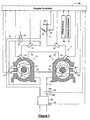
- Figure 1 shows a schematic view of an engine system including an internal combustion engine 1 preferably fueled with gaseous hydrogen.
- the engine system is to be mounted on a vehicle, such as an automotive vehicle, and its output is to be transmitted to vehicle driving wheels through a power transmission mechanism as is well known in the art.
- the engine system comprises an intake air passage 2 for inducting fresh air to the engine 1, an exhaust gas passage 3 for expelling an exhaust gas from the engine 1, and an exhaust gas recirculation (EGR) passage 4 for circulating at least a part of the exhaust gas back to the intake air passage 2.
- EGR exhaust gas recirculation
- the engine 1 preferably is a rotary piston engine having one or more, preferably two substantially triangular shaped rotors 11 and 21.
- the rotary piston engine 1 has one or more, preferably two rotor housings 10 and 20, which are arranged at both or substantially opposite sides of an intermediate housing not shown and between front and rear housings also not shown.
- the rotors 11 and 21 are housed respectively within the rotor housings 10 and 20.
- the inner periphery of the rotor housing 10, the outer periphery of the rotor 11, and the intermediate and front housings collectively define three combustion chambers, while the inner periphery of the rotor housing 20 and the others define three combustion chambers as well.
- the rotors 11 and 21 are arranged rotatably around eccentric shafts 12 and 22, which preferably have a common rotational axis also common with an output shaft of the engine 1.
- each rotor makes three rotations and causes the operational chambers to change the volumes and make an engine cycle (Otto cycle).
- An intake port 2a is arranged in one of the rotor, intermediate and front or rear housings so as to communicate to a combustion chamber in an intake stroke. Also, an exhaust port 3a is arranged in one of the housings so as to communicate to a combustion chamber in an exhaust stroke.
- At least pairs of spark plugs 13 and 23 are arranged in respective ones of the housings 10, 20 so as to substantially face a combustion chamber in compression and expansion strokes.
- the spark plug 13, 23 is coupled to an ignition circuit not shown.
- the ignition circuit is controlled by an engine controller 100 so that the spark plug 13, 23 can spark at desired (predetermined or predeterminable) timing determined by the engine controller 100.
- Direct fuel injectors 14 and 24 are also arranged in respective ones of the housings 10, 20 respectively so as to substantially face an operational chamber in intake and compression strokes.
- the direct fuel injectors 14 and 24 are supplied with the fuel from a fuel storage tank (particularly with the gaseous hydrogen fuel from a hydrogen storage tank, such as a metal hydrate tank), through a fuel supply system not shown.
- the direct fuel injector preferably has a solenoid valve inside. The solenoid valve is actuated by a driver circuit not shown which is controlled by the engine controller 100. Therefore, the direct fuel injector 14, 24 can directly inject fuel (preferably gaseous hydrogen) directly into a combustion chamber in a compression stroke at desired (predetermined or predeterminable) timing determined by the engine controller 100.
- the air and fuel mixture can be combusted even if the overall air fuel ratio of the charged mixture is substantially leaner than the stoichiometry. At that time the air fuel mixture preferably is stratified. On the other hand, when the fuel is injected in an intake stroke, the air fuel mixture will be substantially homogenous.
- port fuel injectors 15 and 25 are arranged in or at the intake ports 2a.
- the port fuel injector 15, 25 is also supplied with fuel from the fuel storage tank (preferably with gaseous hydrogen fuel from the hydrogen storage tank) through the fuel supply system, and has a solenoid valve that is actuated by a driver circuit which is controlled by the engine controller 100.
- the port fuel injector 15, 25 can inject fuel (preferably gaseous hydrogen) into the intake port 2a at desired timing determined by the engine controller 100. Therefore, the port fuel injector 15, 25 can inject fuel (preferably gaseous hydrogen fuel) into the intake port 2a at desired (predetermined or predeterminable) timing determined by the engine controller 100.
- the injected fuel and air are inducted from the intake port 2a into a combustion chamber, the air and fuel mixture is substantially homogeneous.
- an airflow meter 30 (as a preferred air flow or air mass sensor) and a throttle valve 31 are arranged in that order from the upstream side.
- the airflow meter 30 detects airflow or air mass through the intake passage 2 and outputs a corresponding signal to the engine controller 100.
- a throttle valve actuator 42 actuates the throttle valve 31 and adjusts its opening in accordance with a signal from the engine controller 100.
- an EGR valve 35 is arranged, and actuated by an EGR actuator 43 which adjusts an opening of the EGR valve 35 in accordance with a signal from the engine controller 100.
- a three-way catalyst converter 32 preferably is arranged in the exhaust passage 3.
- the three-way catalyst converter 32 has a conventional structure preferably comprising a casing and a catalyst brick sustained in the casing.
- the catalyst brick comprises a honeycomb shaped carrier, and a catalyst layer coated on the carrier.
- the honeycomb shaped carrier may be made of porous material such as cordierite.
- an upstream oxygen sensor 33 is arranged, which detects a concentration of oxygen in the exhaust gas and outputs a corresponding signal corresponding to (such as an electric current in proportion to) the detected oxygen concentration as described in greater detail below. It may be called a linear sensor because of the preferred linearity of its output.
- the downstream sensor 34 may be arranged on the casing of the catalyst converter for a simpler assembly process of an entire exhaust system. It is preferably arranged downstream of the catalyst brick, while it can be arranged between the bricks if there are a plurality of bricks.
- Figure 2 shows a detailed structure of the upstream sensor 33. It comprises a sensor element portion 33a, a heater 33b that is basically comprised of an electric resistor and arranged in the proximity of the sensor element part 33a and can heat it by transmitting (preferably electrically) generated heat, a sensor circuit 33c, and a heater circuit 33d that can keep the sensor element portion 33a at a predetermined or predeterminable temperature.
- the sensor element portion 33a preferably has an oxygen cell element 33e and an oxygen pump element 33f made of oxygen ion conductive solid electrolyte material such as zirconia.
- the oxygen cell element 33e generates electricity or a potential difference at its both sides in dependence on a ratio of oxygen concentrations between at its both sides, white the oxygen pump element 33f pumps oxygen from its one side to the other in dependence on electricity or a potential difference applied to its both sides.
- Electrode layers 33e' are formed on the both sides of the oxygen cell element 33e, and electrode layers 33f are formed on the both sides of the oxygen pump element 33f.
- a dispersion chamber 33h comprises or is preferably defined by the pair of oxygen pump elements 33e and 33f, a part of a casing of the sensor element 33a, and a dispersion layer 33g.
- the dispersion chamber 33h communicates with the exhaust passage 3 through the dispersion layer 33g so that the exhaust gas flows between the exhaust passage 3 and the dispersion layer 33g preferably at substantially constant dispersion rate.
- a relative oxygen concentration chamber 33i is formed at one side of the oxygen cell element 33e, and an oxygen concentration therein preferably is maintained substantially constant, for example, by communicating to the atmosphere.
- the sensor circuit 33c is connected to the sensor element portion 33a, and comprises an operational amplifier 33j, a resistor 33k, and output terminals 33m.
- oxygen ion conductive solid electrolyte material used for the oxygen cell element 33e and the oxygen pump element 33f is arranged between two chambers of different oxygen partial pressures (or concentrations)
- oxygen ions pass through the element depending on a ratio of the oxygen partial pressures of the both chambers substantially until the equilibrium, and generate electromotive force, thereby functioning as an electric cell.
- there is a voltage difference between the both sides of the material it pumps or translates oxygen from one side to the other.
- the operational amplifier 33j substantially adjusts current flowing to the oxygen pump element 33f in accordance with change of voltage generated at the oxygen cell element 33e.
- the oxygen pump element 33f pumps out the oxygen from the dispersion chamber 33h to the outside.
- oxygen in exhaust gas in the dispersion chamber 33h decreases, the oxygen pump element 33f pumps oxygen into the dispersion chamber 33h from the outside.
- the pumping function of the oxygen pump element 33e is going to maintain a state corresponding to the stoichiometric air fuel ratio in the dispersion chamber 33h.
- an amount of the oxygen pumped out by the oxygen pump element 33f is in proportion to a difference between an oxygen concentration in the exhaust passage 3 and an oxygen concentration in the dispersion chamber 33h which is supposedly corresponding to the stoichiometric air fuel ratio particularly due to the function of the oxygen cell element 33e.
- the current adjusted by the operational amplifier 33j for actuating the oxygen pump element 33f flows through the resistor 33k. At the terminals 33m, a voltage in proportion to the current and the oxygen concentration in the exhaust passage 3 can be output.
- FIG. 3 shows the heater 33b and the heater circuit 33d.
- the heater 33b is basically comprised of a resistor, and the heater circuit 33d comprises a bridge circuit including resistors 33n, 33p and 33q, a transistor 33r, and an operational amplifier 33s.
- the resistor of the heater 33b changes its electric resistance depending on its temperature, as is well known in the art.
- the resistors 33n, 33p and 33q do not substantially change their resistances. Therefore, a voltage at a point between the heater 33b and the resistor 33p changes depending on the temperature of the heater 33b.
- a voltage at a point between the resistors 33n and 33q does not substantially change, therefore it can be used as a reference voltage at the operational amplifier 33s.
- Output of the operational amplifier 33s is input to the transistor 33r, and it regulates electric current to the heater 33b in accordance with the temperature of the heater 33b. Therefore, it is preferably feedback controlled to be a temperature substantially corresponding to the reference voltage at the operational amplifier 33s. Although it is not shown, electric supply to the heater circuit 33d can be shut down by a switching relay or a power transistor known in the art, which is controlled by the engine controller 100.
- the downstream lambda sensor 34 basically comprises an oxygen cell element, and preferably does not have an oxygen pump element. Therefore, an output signal of the downstream lambda sensor 34 rapidly changes between below and above a predetermined oxygen concentration. That is, the lambda sensor 34 outputs a first voltage (e.g. of about 1 volt) at an oxygen concentration of exhaust gas generated when mixture richer than the stoichiometric air fuel ratio is combusted and flows, and outputs a second voltage (e.g. of about 0 volt) lower than the first voltage when mixture leaner than the stoichiometric air fuel ratio is combusted and flows. Consequently, it is possible to determine an air fuel ratio of mixture supplied to a combustion chamber is richer or leaner than the stoichiometric air fuel ratio.
- a first voltage e.g. of about 1 volt
- a second voltage e.g. of about 0 volt
- the linear oxygen sensor 33 and the lambda oxygen sensor 34 upstream and downstream of the three way catalyst converter 32, degradation of the catalyst 32 can be detected.
- oxygen in exhaust gas is adsorbed by the catalyst 32 so that an oxygen concentration detected by the downstream lambda sensor 34 is relatively smaller than an oxygen concentration detected by the upstream linear sensor 33.
- oxygen storage capacity is decreased so that detected values by the both sensors 33 and 34 are made similar, and based on this, the degradation of the catalyst 32 can be detected.
- a variation caused by an individual difference or aging can be adjusted as well.
- the engine controller 100 is a microprocessor based controller, and as shown in Figure 1, receives one or more signals from one or more of the following: the airflow meter 30, the upstream linear sensor 33, the downstream lambda sensor 34, an engine speed sensor 40 for detecting an engine rotational speed, an accelerator sensor detecting a position of an accelerator pedal which a driver operates, and other sensors. Based on those input signals, the engine controller 100 computes and outputs signals directly or indirectly, for example through a driver circuit, to the fuel injectors 14, 15, 24, and 25, the spark plugs 13 and 23, the throttle actuator 42, the EGR actuator 43, the switching relay of the heater 33b of the upstream linear sensor 33, and/or other actuators. Although the heater circuit 33d adjusts electricity supplied to the heater 33b of the upstream linear sensor 33, the engine controller 100 may digitally perform the substantially same function as the analogue heater circuit 33d does.
- the engine controller 100 stores in its memory an operational map or table or relationship 110, as shown in Figure 4, which preferably defines three operational modes in accordance with an engine speed which is detected by the engine speed sensor 40 and a desired engine torque which predominantly corresponds to the signal output from the accelerator sensor 41.
- the engine controller 100 computes a target opening of the throttle valve 31 based on the desired torque, the engine speed and the target air fuel ratio, and controls the throttle actuator 42 to meet the target throttle opening.
- a base fuel injection amount is computed based on the desired torque, the engine speed and/or the target air fuel ratio, as well.
- the engine controller 100 adjusts an air fuel ratio of air and fuel mixture supplied to the engine 1 with reference to the operational map 100.
- the engine controller 100 closed the switching relay or power transistor between the power supply and the heater circuit 33d of the upstream linear sensor. Therefore, the heater 33b can receive electricity and maintain the upstream sensor 33 at the predetermined temperature, therefore the sensor 33 is fully operative.
- the fuel injection amount is (preferably feedback) controlled using based on the base fuel injection amount and the output of the upstream linear oxygen sensor 33 to substantially meet the target air fuel ratio.
- the output of the downstream lambda sensor 34 may be used for a correction of the output of the upstream linear sensor 33.
- the EGR valve 35 is opened so that the exhaust gas is re-circulated through the EGR passage 4 to the intake passage 2.
- the exhaust gas re-circulated into the combustion chamber decreases a combustion temperature, and reduces NOx generation during the combustion.
- the direct fuel injectors 14 and 24 inject fuel directly to the combustion chambers.
- the EGR valve 35 is closed, and direct fuel injectors 14 and 24 inject fuel directly to the combustion chambers.
- the EGR valve 35 is closed.
- the direct fuel injectors 14 and 24 inject fuel directly to the combustion chambers, and at the substantially same time, the port fuel injectors 15 and 25 inject fuel to the intake ports 2a, for higher engine output.
- a control routine executed by the engine controller 100 the engine controller 100 reads various signals from the airflow meter 30, the upstream linear sensor 33, the downstream lambda sensor 34, the engine speed sensor 40, and/or the others.
- the routine proceeds to a step S2, and determines whether or not a specified (predetermined or predeterminable) first time period (e.g. of about 20 seconds) has passed since an engine start by reading a counter which is integrated into the engine controller 100, and has started when the engine 1 is determined to start a self rotation and counts up as time goes by.
- the counter may count number of rotations of the engine 1 or number of combustion cycles of the engine 1, from the fuel injection pulse signal sent to the fuel injectors from the engine controller 100.
- the routine proceeds to a step S5, and computes the base fuel injection amount (preferably based on the engine speed, the desired torque and the target air fuel ratio) without taking account of the outputs of either of the upstream linear sensor 33 or the downstream lambda sensor 34 (open control).
- step S6 the engine controller 100 actuates the direct fuel injectors 14 and 24 to inject the base fuel amount determined at the step S5 at a desired timing without actuating the port fuel injectors 15 and 25 (direct injection).
- the engine controller 100 controls the throttle actuator 42 to regulate intake airflow to the engine 1, thereby preferably causing the direct fuel injectors 14 and 24 and the throttle valve 31 to function collectively as an air-fuel regulator to adjust the air-fuel mixture supplied to the engine 1.
- step S7 the engine controller 100 controls the EGR actuator 43 to close the EGR valve 35. Then, the routine returns.
- the upstream linear sensor 33 and the downstream lambda sensor 34 are likely not to reach active temperatures. Then, it may be difficult to make precise feedback control based on the outputs of these sensors 33 and 34. Therefore, the feedback control is not made, but the open control is made with the target air fuel ratio to substantially be the stoichiomery.
- catalytic reaction of the exhaust gas over the three-way catalyst converter 32 occurs and generates heat to increase the gas temperature downstream of the catalyst converter 32. Therefore, the downstream lambda sensor 34 increases its temperature at a greater rate, as shown in Figure 6 by a line A.
- the specified first time period (e.g. of about 20 seconds) for the determination at the step S2 may be predetermined from an experiment or test, particularly not limited to 20 seconds, but may be a time period sufficient for the lambda sensor 34 to substantially reach the active temperature.
- the routine proceeds to a step S8, and determines whether or not a second time period (e.g. of two minutes) longer than the first time period has passed after the engine start by reading the counter described above. If it is determined that the second time period (e.g.
- the routine proceeds to a step S11, and computes the base fuel injection amount (preferably based on the engine speed, the desired torque and the target air fuel ratio), and computes the fuel injection amount, preferably based on the base fuel injection amount and an output signal from the downstream lambda sensor 34 (feedback control).
- step S12 the engine controller 100 actuates the direct fuel injectors 14 and 24 at a desired (predetermined or predeterminable) timing preferably without actuating the port fuel injectors 15 and 25 (direct injection).
- step S13 the engine controller 100 controls the EGR actuator 43 to close the EGR valve 35. Then, the routine returns.
- the output of the upstream linear sensor 33 may be taken account of to some extent for a purpose of watching the function of the lambda sensor 34.
- the second time period e.g. of about two minutes for the determination at the step S8 may be predetermined from an experiment or test, not limited to two minutes, but may be a time period sufficient for the linear sensor 34 to substantially reach the active temperature. Further, it may be number of rotations or combustion events of the engine 1 as described above.
- the routine proceeds to a step S14, and supplies electricity the heater 33b through the heater circuit 33d of the linear sensor 33 by the engine controller 100 closing the switching relay. Then, the heater circuit 33d, as described above, controls the heater 33b to maintain the linear sensor 33 substantially at the predetermined temperature. Then, the routine proceeds to a step S15, and determines the engine operating condition is in which of the regions 112, 114, and 116 in the map 110 of Figure 4, preferably based on the desired torque and the engine speed.
- the feedback amount by the output of the linear sensor 33 is decrementally corrected by a predetermined or predeterminable amount, and if the lambda sensor 34 determines it is richer than the stoichiometry, the feedback correction amount by the output of the linear sensor 33 is incrementally corrected by a predetermined or predeterminable amount.
- the routine proceeds to a step S18, and the engine controller 100 actuates the direct fuel injectors 14 and 24 at a desired timing without actuating the port fuel injectors 15 and 25 (direct injection).
- the routine proceeds to a step S19, and the engine controller 100 controls the EGR actuator 43 to open the EGR valve 35 to re-circulate part of exhaust gas to the intake passage 2 through the EGR passage 4. With this exhaust gas recirculation, the combustion temperature can be decreased to reduce the NOx emission. Then, the routine returns.
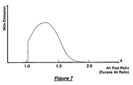
- Figure 7 shows a relationship between NOx emission and an excess air ratio ⁇ .
- the routine proceeds to a step S22, and the engine controller 100 actuates the direct fuel injectors 14 and 24 at a desired timing without actuating the port fuel injectors 15 and 25 (direct injection). Finally, the routine proceeds to a step S23, and the engine controller 100 controls the EGR actuator 43 to close the EGR valve 35. Then, the routine returns.
- the routine proceeds to a step S26, and the engine controller 100 actuates the direct fuel injectors 14 and 24 and the port fuel injectors 15 and 25 at respective desired timings (direct injection plus port injection).
- the engine controller 100 controls the throttle actuator 42 to regulate intake airflow to the engine 1, thereby causing the direct fuel injectors 14 and 24, the port fuel injectors 15 and 25 and the throttle valve 31 to preferably function collectively as the air-fuel regulator to adjust the air-fuel mixture supplied to the engine 1.
- the routine proceeds to a step S27, and the engine controller 100 controls the EGR actuator 43 to close the EGR valve 35. Then, the routine returns.
- the downstream lambda sensor 34 arranged has substantially no condensed water on its surface thanks to the catalyst converter 32 arranged upstream of the downstream lambda sensor 34. Also, the exhaust gas reacted and heated at the catalyst converter 32 may cause the lambda sensor 34 to more quickly reach the active temperature so that the air fuel ratio can be precisely feedback controlled based on the output of the lambda sensor 34.
- the oxygen sensors 33 and 34 are supposed to substantially reach the respective active temperatures by determining a time period since an engine start at the steps S2 and S8.
- a temperature sensor may be provided and detect a temperature of the linear sensor 33 and/or the lambda sensor 34. Then, at the step S2 or S8 of the control routine of Figure 5, it may be determined whether or not the detected temperature of the sensor 33 and/or 34 is higher than a predetermined or predeterminable temperature.
- the temperatures of the sensors 33 and 34 may be estimated based on cumulated rotations of the engine 1 since an engine start, cumulated fuel injection amount since an engine start, other parameters including the time period since an engine start, an engine temperature, and an atmospheric temperature, or a combination of any of the above.
- the engine 1 is not limited to the rotary piston engine, but may be any type of internal combustion engines including a spark ignited engine having a reciprocating piston with direct fuel injection or port fuel injection.
- the fuel supplied to the engine is not limited to the gaseous hydrogen described above, but it may be hydrocarbon based fuels including gasoline, diesel oil and/or ethanol.
- the upstream sensor 33 is not limited to the specific type of linear sensor described above, but may be a different type of sensor showing a linearity of the output without the oxygen pump element, or a lambda sensor like the downstream sensor 34 if the target air fuel ratio is always set the stoichiometry.
- the heater 33b and the heater circuit 33d are not limited to the above described. Specifically, instead of turning on and off the electricity to the heater 33b, the engine controller 100 may adjust the electricity by controlling a power transistor such as the transistor 33r in Figure 3. In that case, instead of stopping the electricity to the heater 33b at the steps S3 and S9, small amount of electricity can be supplied to the heater 33b. That amount is much smaller than what may be supplied at the step S14. Then, the upstream linear sensor can more quickly substantially reach the active temperature without a risk of the excessive surface distortion.
- a power transistor such as the transistor 33r in Figure 3.
- the downstream sensor 34 does not have any heater
- the sensor 34 may have an electric heater. Since the downstream sensor 34 is arranged downstream of at least one brick of the catalyst converter 33 which blocks water from condensing on the sensor 34, the heater of the downstream sensor 34 may be activated just after an engine start so that an air fuel ratio feedback control can be started further earlier.
- the heater is not only limited to the above electric heater 34b, but may be of any other suitable type having a controllable heat deployment or heat generation.
Landscapes
- Engineering & Computer Science (AREA)
- Chemical & Material Sciences (AREA)
- Combustion & Propulsion (AREA)
- Mechanical Engineering (AREA)
- General Engineering & Computer Science (AREA)
- Electrical Control Of Air Or Fuel Supplied To Internal-Combustion Engine (AREA)
- Combined Controls Of Internal Combustion Engines (AREA)
- Output Control And Ontrol Of Special Type Engine (AREA)
- Exhaust Gas After Treatment (AREA)
Abstract
Description
- The present description relates to a method of controlling an internal combustion engine, and more particularly relates to a method of feedback controlling an air fuel ratio of air fuel mixture supplied to an internal combustion engine using a heated exhaust gas oxygen sensor.
- There is known and presented, for example in
U.S. Patent No. 6,848,439 , an exhaust gas oxygen sensor arranged in an exhaust passage between an internal combustion engine and a catalytic converter. The sensor is capable of outputting a signal that corresponds linearly to the oxygen concentration in the exhaust gases. The '439 patent also shows a method of using the sensor output for feedback controlling an air-fuel mixture to an internal combustion engine. The exhaust gas oxygen sensor outputs a linear signal when its temperature is within a higher operative temperature range, between about 700-800°C for example. On the other hand, the sensor outputs a non-linear signal around the stoichiometric air-fuel ratio at a lower operative temperature range, between about 300-400°C for example. The exhaust gas oxygen sensor is provided with a heater, which may be used to heat the sensor temperature to the operative range. - When the exhaust gas oxygen sensor is cooled down after an engine stop and an internal combustion engine is started again, a water content of the exhaust gas or combusted gas may be partly condensed by contacting the sensor surface. If the heater is then used to heat the exhaust gas oxygen sensor, the condensed water may cause the sensor output to degrade. The '439 patent describes a method to avoid such degradation by choosing the lower temperature range as its target temperature. The '439 patent also describes using the sensor at lower operating temperatures to provide feedback control of engine air fuel mixtures around the stoichiometric air fuel ratio within a predetermined time period after an engine start.
- However, it is possible under certain circumstances to increase the amount of water in the exhaust gas that condenses on the sensor surface. For example, when hydrogen is used as a fuel instead of fossil fuels, such as gasoline, combustion of hydrogen may create more water in the exhaust gas because hydrogen readily combines with air to produce water. As the amount of the condensed water increases, it may make it difficult to heat the sensor after an engine start, even to the lower target temperature. Further, since combusted hydrogen exhibits lower exhaust gas temperatures, the time period that condensation occurs in the exhaust system can be increased when compared to combusted fossil fuels. The condensation may make it difficult to precisely feedback control the engine air-fuel ratio based on feedback from the sensor output. Consequently, engine emissions and fuel economy may be degraded when exhaust gases condensate into water in the exhaust system.
- Therefore, there is a need to provide an improved feedback controlling of an air-fuel ratio using a heated exhaust gas oxygen sensor.
- This object is solved according to the invention by the features of the independent claims. Preferred embodiments of the invention are subject of the dependent claims. According to the invention there is provided a method of controlling an internal combustion engine system. The method comprises supplying a first amount of energy (preferably of electric energy) to heat to an upstream sensor located in an exhaust gas passage from the internal combustion engine and upstream of an exhaust gas after-treatment device and adjusting an air fuel mixture supplied to the internal combustion engine based on an output of the upstream sensor during a first engine operating condition. The method further comprises supplying a second amount of energy (preferably electric energy), which is smaller than the first amount, to heat the upstream sensor and adjusting the air-fuel mixture based on an output of a downstream sensor located in the exhaust gas passage and downstream of the exhaust gas after-treatment device during a second engine operating condition.
- By adjusting the air fuel-ratio based on an output of the downstream sensor during the second engine operating condition, the air fuel-ratio can be adjusted under less influence from the condensed water. Since the downstream sensor is located downstream of the exhaust gas after-treatment device, much of the water vapor in the exhaust gas may be condensed before the exhaust gases reach the downstream sensor. This allows the downstream sensor to operate with less influence from the condensing water vapor. Therefore, during the second engine operating condition, the engine air fuel ratio can be more precisely adjusted so that engine exhaust emissions and fuel economy may be improved.
- According to a preferred embodiment of the invention, the air-fuel mixture is feedback controlled around an air fuel ratio leaner than the stoichiometric air fuel ratio during said first engine operating condition and the stoichiometric air fuel ratio during said second engine operating condition.
- Preferably, the first amount of energy (preferably of electric energy) is adjusted to feedback control a temperature of said upstream sensor.
- Further preferably, the second amount of energy (preferably of electric energy) is zero.
- Still further preferably, a temperature of said upstream sensor is above a predetermined temperature during said first engine operating condition and below said predetermined temperature during said second engine operating condition.
- Further preferably, said first amount of energy (preferably of electric energy) is adjusted to regulate the temperature of said upstream sensor to a temperature which is higher than said predetermined temperature.
- Still further preferably, said second operating condition occurs within a predetermined period after an engine start.
- Most preferably, said predetermined period is determined based on a number of engine combustion events.
- According to the invention, there is further provided an engine system comprising:
- an internal combustion engine;
- an air-fuel regulator configured to adjust an air-fuel mixture supplied to said internal combustion engine;
- an exhaust gas passage through which exhaust gas flows from said internal combustion engine;
- an exhaust gas after-treatment device arranged in said exhaust gas passage;
- an upstream sensor arranged in said exhaust gas passage and between said internal combustion engine and said exhaust gas after-treatment device and configured to detect an oxygen concentration in the exhaust gas and to output a first signal;
- a heater (preferably an electric heater) capable of heating said upstream sensor with supplied energy (preferably with supplied electric energy);
- a downstream sensor arranged in said exhaust gas passage and downstream of said exhaust gas after-treatment device and configured to detect an oxygen concentration in the exhaust gas and to output a second signal; and
- a controller configured to control the supplied energy (preferably the supplied electric energy) to said heater to be greater during a first engine operating condition than during a second engine operating condition,
- According to a preferred embodiment of the invention, hydrogen is supplied to said internal combustion engine as fuel.
- Most preferably, the engine system further comprises a counter or timer configured to count or measure an elapsed period since an engine start, and wherein said controller is further configured to determine a transition from said second engine operating condition to said first engine operating condition when said counter has counted a predetermined value.
- In another aspect, the method comprises adjusting an air-fuel mixture supplied to the internal combustion engine by more heavily weighting an output of the downstream sensor than an output of the upstream sensor during a first predetermined or predeterminable period, and adjusting the air-fuel mixture by more heavily weighting the output of the upstream sensor than the output of the downstream sensor after the first predetermined period. By adjusting the air-fuel mixture by more heavily weighting the output of the downstream sensor prior to more heavily weighting the output of the upstream sensor, the air-fuel mixture can be adjusted under less influence of the water in the exhaust gas because the water is less likely to condense as the period goes by and the engine system temperature increases. Therefore, the engine air fuel ratio can be more precisely adjusted over time.
- In a further aspect of the invention, there is provided a computer program product, preferably embodied in a computer-readable storage medium or as a signal, comprising computer readable instructions which when loaded and executed on a suitable system execute the steps of a method according to the invention or a preferred embodiment thereof.
- According to a preferred embodiment of the invention, the air-fuel mixture is feedback controlled based on the output of said upstream or downstream sensor.
- Preferably, said upstream and downstream sensors detect an oxygen concentration in said exhaust passage.
- Further preferably, the air-fuel mixture is feedback controlled around a stoichiometric air fuel ratio during said second engine operating condition.
- Most preferably, the air-fuel mixture is feedback controlled around an air fuel ratio leaner than the stoichiometric air fuel ratio during said first engine operating condition.
- According to a preferred embodiment of the invention, said second operating condition occurs within a predetermined period after an engine start. Preferably, said predetermined period is a time period or a number of engine combustion events.
- According to a further aspect of the invention, there is provided a method of controlling an internal combustion engine system having an upstream sensor located in said exhaust gas passage from an internal combustion engine and upstream of an exhaust gas after-treatment device and a downstream sensor located in said exhaust gas passage and downstream of said exhaust gas after-treatment, comprising:
- adjusting an air-fuel mixture supplied to said internal combustion engine by more heavily weighting an output of said downstream sensor than an output of said upstream sensor during a first predetermined period; and
- adjusting the air-fuel mixture by more heavily weighting the output of said upstream sensor than the output of said downstream sensor after said first predetermined period.
- According to a preferred embodiment of the invention, the air fuel mixture is feedback controlled based on the output of said upstream or downstream sensor.
- Preferably, the method further comprises adjusting the air-fuel mixture without said feedback control during a second predetermined period before said predetermined period.
- Further preferably, the method further comprises supplying electric energy to heat said upstream sensor after said first predetermined period.
- Most preferably, the air-fuel mixture is feedback controlled around an air fuel ratio leaner than a stoichiometric air fuel ratio based on the output of said upstream sensor after said first predetermined period.
These and other objects, features and advantages of the present invention will become more apparent upon reading of the following detailed description of preferred embodiments and accompanying drawings. It should be understood that even though embodiments are separately described, single features thereof may be combined to additional embodiments. - Figure 1 shows a schematic view of an engine system in accordance with an embodiment of the present description;
- Figure 2 is a circuit diagram showing an upstream sensor which detects an oxygen concentration in the exhaust gas and has an electric heater in accordance with the embodiment;
- Figure 3 is a circuit diagram the electric heater of the upstream sensor in accordance with the embodiment;
- Figure 4 is a map which defines engine operating regions on an engine speed and desired engine torque;
- Figure 5 is a flowchart showing a routine to control the engine system in accordance with the embodiment of the present description;
- Figure 6 shows time charts of temperatures of exhaust gas oxygen sensors, heater control, and fuel control; and
- Figure 7 shows a graph of NOx emission versus air fuel ratios.
- A preferred embodiment of the present description will now be described with reference to the drawings, starting with Figure 1, which shows a schematic view of an engine system including an
internal combustion engine 1 preferably fueled with gaseous hydrogen. The engine system is to be mounted on a vehicle, such as an automotive vehicle, and its output is to be transmitted to vehicle driving wheels through a power transmission mechanism as is well known in the art. - The engine system comprises an
intake air passage 2 for inducting fresh air to theengine 1, anexhaust gas passage 3 for expelling an exhaust gas from theengine 1, and an exhaust gas recirculation (EGR)passage 4 for circulating at least a part of the exhaust gas back to theintake air passage 2. - The
engine 1 preferably is a rotary piston engine having one or more, preferably two substantially triangular shapedrotors rotary piston engine 1 has one or more, preferably tworotor housings rotors rotor housings rotor housing 10, the outer periphery of therotor 11, and the intermediate and front housings collectively define three combustion chambers, while the inner periphery of therotor housing 20 and the others define three combustion chambers as well. Therotors eccentric shafts engine 1. When the output shaft makes one rotation, each rotor makes three rotations and causes the operational chambers to change the volumes and make an engine cycle (Otto cycle). - An
intake port 2a is arranged in one of the rotor, intermediate and front or rear housings so as to communicate to a combustion chamber in an intake stroke. Also, anexhaust port 3a is arranged in one of the housings so as to communicate to a combustion chamber in an exhaust stroke. - At least pairs of
spark plugs 13 and 23 are arranged in respective ones of thehousings spark plug 13, 23 is coupled to an ignition circuit not shown. The ignition circuit is controlled by anengine controller 100 so that thespark plug 13, 23 can spark at desired (predetermined or predeterminable) timing determined by theengine controller 100. -
Direct fuel injectors housings direct fuel injectors engine controller 100. Therefore, thedirect fuel injector engine controller 100. When the fuel is injected in a compression stroke, the air and fuel mixture can be combusted even if the overall air fuel ratio of the charged mixture is substantially leaner than the stoichiometry. At that time the air fuel mixture preferably is stratified. On the other hand, when the fuel is injected in an intake stroke, the air fuel mixture will be substantially homogenous. - Also,
port fuel injectors intake ports 2a. Theport fuel injector engine controller 100. Theport fuel injector intake port 2a at desired timing determined by theengine controller 100. Therefore, theport fuel injector intake port 2a at desired (predetermined or predeterminable) timing determined by theengine controller 100. When the injected fuel and air are inducted from theintake port 2a into a combustion chamber, the air and fuel mixture is substantially homogeneous. - In the
intake passage 2, an airflow meter 30 (as a preferred air flow or air mass sensor) and athrottle valve 31 are arranged in that order from the upstream side. Theairflow meter 30 detects airflow or air mass through theintake passage 2 and outputs a corresponding signal to theengine controller 100. Athrottle valve actuator 42 actuates thethrottle valve 31 and adjusts its opening in accordance with a signal from theengine controller 100. - In the
EGR passage 4, anEGR valve 35 is arranged, and actuated by anEGR actuator 43 which adjusts an opening of theEGR valve 35 in accordance with a signal from theengine controller 100. - In the
exhaust passage 3, a three-way catalyst converter 32 preferably is arranged. The three-way catalyst converter 32 has a conventional structure preferably comprising a casing and a catalyst brick sustained in the casing. The catalyst brick comprises a honeycomb shaped carrier, and a catalyst layer coated on the carrier. The honeycomb shaped carrier may be made of porous material such as cordierite. Upstream of thecatalyst converter 32 in theexhaust passage 3, anupstream oxygen sensor 33 is arranged, which detects a concentration of oxygen in the exhaust gas and outputs a corresponding signal corresponding to (such as an electric current in proportion to) the detected oxygen concentration as described in greater detail below. It may be called a linear sensor because of the preferred linearity of its output. - Downstream of the
catalyst converter 32 in theexhaust passage 3, adownstream oxygen sensor 34 is arranged, which also detects a concentration of oxygen in the exhaust gas, but outputs a corresponding signal (such as an electric current) that abruptly changes around or when close to the stoichiometric air fuel ratio. Therefore, it may be called a lambda sensor since the stoichiometric air fuel ratio corresponding to an excessive air ratio λ (lambda) = 1. Thedownstream sensor 34 may be arranged on the casing of the catalyst converter for a simpler assembly process of an entire exhaust system. It is preferably arranged downstream of the catalyst brick, while it can be arranged between the bricks if there are a plurality of bricks. - Figure 2 shows a detailed structure of the
upstream sensor 33. It comprises asensor element portion 33a, aheater 33b that is basically comprised of an electric resistor and arranged in the proximity of thesensor element part 33a and can heat it by transmitting (preferably electrically) generated heat, a sensor circuit 33c, and aheater circuit 33d that can keep thesensor element portion 33a at a predetermined or predeterminable temperature. - The
sensor element portion 33a preferably has anoxygen cell element 33e and anoxygen pump element 33f made of oxygen ion conductive solid electrolyte material such as zirconia. Theoxygen cell element 33e generates electricity or a potential difference at its both sides in dependence on a ratio of oxygen concentrations between at its both sides, white theoxygen pump element 33f pumps oxygen from its one side to the other in dependence on electricity or a potential difference applied to its both sides. Electrode layers 33e' are formed on the both sides of theoxygen cell element 33e, andelectrode layers 33f are formed on the both sides of theoxygen pump element 33f. - A
dispersion chamber 33h comprises or is preferably defined by the pair ofoxygen pump elements sensor element 33a, and adispersion layer 33g. Thedispersion chamber 33h communicates with theexhaust passage 3 through thedispersion layer 33g so that the exhaust gas flows between theexhaust passage 3 and thedispersion layer 33g preferably at substantially constant dispersion rate. A relativeoxygen concentration chamber 33i is formed at one side of theoxygen cell element 33e, and an oxygen concentration therein preferably is maintained substantially constant, for example, by communicating to the atmosphere. - The sensor circuit 33c is connected to the
sensor element portion 33a, and comprises anoperational amplifier 33j, aresistor 33k, andoutput terminals 33m. - When the oxygen ion conductive solid electrolyte material used for the
oxygen cell element 33e and theoxygen pump element 33f is arranged between two chambers of different oxygen partial pressures (or concentrations), oxygen ions pass through the element depending on a ratio of the oxygen partial pressures of the both chambers substantially until the equilibrium, and generate electromotive force, thereby functioning as an electric cell. On the other hand, when there is a voltage difference between the both sides of the material, it pumps or translates oxygen from one side to the other. - Then, the
operational amplifier 33j substantially adjusts current flowing to theoxygen pump element 33f in accordance with change of voltage generated at theoxygen cell element 33e. When oxygen in exhaust gas in thedispersion chamber 33h increases, theoxygen pump element 33f pumps out the oxygen from thedispersion chamber 33h to the outside. When oxygen in exhaust gas in thedispersion chamber 33h decreases, theoxygen pump element 33f pumps oxygen into thedispersion chamber 33h from the outside. The pumping function of theoxygen pump element 33e is going to maintain a state corresponding to the stoichiometric air fuel ratio in thedispersion chamber 33h. But, the exhaust gas flows into thedispersion chamber 33h through thedispersion layer 33g at the constant rate, and the pumping function does not stop unless an oxygen concentration in thedispersion chamber 33h matches to the stoichiometric air fuel ratio. Therefore, an amount of the oxygen pumped out by theoxygen pump element 33f is in proportion to a difference between an oxygen concentration in theexhaust passage 3 and an oxygen concentration in thedispersion chamber 33h which is supposedly corresponding to the stoichiometric air fuel ratio particularly due to the function of theoxygen cell element 33e. Then, the current adjusted by theoperational amplifier 33j for actuating theoxygen pump element 33f flows through theresistor 33k. At theterminals 33m, a voltage in proportion to the current and the oxygen concentration in theexhaust passage 3 can be output. - Figure 3 shows the
heater 33b and theheater circuit 33d. Theheater 33b is basically comprised of a resistor, and theheater circuit 33d comprises a bridgecircuit including resistors transistor 33r, and anoperational amplifier 33s. The resistor of theheater 33b changes its electric resistance depending on its temperature, as is well known in the art. On the other hand, theresistors heater 33b and theresistor 33p changes depending on the temperature of theheater 33b. On the other hand, a voltage at a point between theresistors operational amplifier 33s. Output of theoperational amplifier 33s is input to thetransistor 33r, and it regulates electric current to theheater 33b in accordance with the temperature of theheater 33b. Therefore, it is preferably feedback controlled to be a temperature substantially corresponding to the reference voltage at theoperational amplifier 33s. Although it is not shown, electric supply to theheater circuit 33d can be shut down by a switching relay or a power transistor known in the art, which is controlled by theengine controller 100. - The
downstream lambda sensor 34 basically comprises an oxygen cell element, and preferably does not have an oxygen pump element. Therefore, an output signal of thedownstream lambda sensor 34 rapidly changes between below and above a predetermined oxygen concentration. That is, thelambda sensor 34 outputs a first voltage (e.g. of about 1 volt) at an oxygen concentration of exhaust gas generated when mixture richer than the stoichiometric air fuel ratio is combusted and flows, and outputs a second voltage (e.g. of about 0 volt) lower than the first voltage when mixture leaner than the stoichiometric air fuel ratio is combusted and flows. Consequently, it is possible to determine an air fuel ratio of mixture supplied to a combustion chamber is richer or leaner than the stoichiometric air fuel ratio. - By arranging the
linear oxygen sensor 33 and thelambda oxygen sensor 34 upstream and downstream of the threeway catalyst converter 32, degradation of thecatalyst 32 can be detected. In particular, when thecatalyst 32 functions normally, oxygen in exhaust gas is adsorbed by thecatalyst 32 so that an oxygen concentration detected by thedownstream lambda sensor 34 is relatively smaller than an oxygen concentration detected by the upstreamlinear sensor 33. However, when thecatalyst 32 is degraded, oxygen storage capacity is decreased so that detected values by the bothsensors catalyst 32 can be detected. Also, by providing the twosensors - The
engine controller 100 is a microprocessor based controller, and as shown in Figure 1, receives one or more signals from one or more of the following: theairflow meter 30, the upstreamlinear sensor 33, thedownstream lambda sensor 34, anengine speed sensor 40 for detecting an engine rotational speed, an accelerator sensor detecting a position of an accelerator pedal which a driver operates, and other sensors. Based on those input signals, theengine controller 100 computes and outputs signals directly or indirectly, for example through a driver circuit, to thefuel injectors throttle actuator 42, theEGR actuator 43, the switching relay of theheater 33b of the upstreamlinear sensor 33, and/or other actuators. Although theheater circuit 33d adjusts electricity supplied to theheater 33b of the upstreamlinear sensor 33, theengine controller 100 may digitally perform the substantially same function as theanalogue heater circuit 33d does. - The
engine controller 100 stores in its memory an operational map or table orrelationship 110, as shown in Figure 4, which preferably defines three operational modes in accordance with an engine speed which is detected by theengine speed sensor 40 and a desired engine torque which predominantly corresponds to the signal output from theaccelerator sensor 41. The operational map defines a λ=1 mode in a lower speed andhigher torque region 112, a lean mode (1<λ≈2) in a lower speed andlower torque region 114, and a high power mode a high power lean region (λ=1.4-1.6) in ahigher speed region 116. - The
engine controller 100 computes a target opening of thethrottle valve 31 based on the desired torque, the engine speed and the target air fuel ratio, and controls thethrottle actuator 42 to meet the target throttle opening. A base fuel injection amount is computed based on the desired torque, the engine speed and/or the target air fuel ratio, as well. - When a predetermined time period, for example about two minutes, has passed, the
engine controller 100 adjusts an air fuel ratio of air and fuel mixture supplied to theengine 1 with reference to theoperational map 100. At this time, theengine controller 100 closed the switching relay or power transistor between the power supply and theheater circuit 33d of the upstream linear sensor. Therefore, theheater 33b can receive electricity and maintain theupstream sensor 33 at the predetermined temperature, therefore thesensor 33 is fully operative. The fuel injection amount is (preferably feedback) controlled using based on the base fuel injection amount and the output of the upstreamlinear oxygen sensor 33 to substantially meet the target air fuel ratio. At this time, the output of thedownstream lambda sensor 34 may be used for a correction of the output of the upstreamlinear sensor 33. - In the lower speed and
higher torque region 112, a target air fuel ratio substantially is set the stoichiometric air fuel ratio (corresponding to λ=1). TheEGR valve 35 is opened so that the exhaust gas is re-circulated through theEGR passage 4 to theintake passage 2. The exhaust gas re-circulated into the combustion chamber decreases a combustion temperature, and reduces NOx generation during the combustion. Thedirect fuel injectors - In the lower speed and
lower torque region 114, the target air fuel ratio is set an air fuel ratio leaner than the stoichiometric air fuel ratio, for example corresponding to λ=2. TheEGR valve 35 is closed, anddirect fuel injectors - In the higher speed region, the target air fuel ratio is set an air fuel ratio leaner than the stoichioimetric air fuel ratio, for example substantially corresponding to λ=1.4-1.6, which is, in the case of using gaseous hydrogen as fuel, the leanest air fuel ratio as far as pre-ignition that is self ignition before spark ignition by the spark plugs 13 or 23 does not occur. The
EGR valve 35 is closed. Thedirect fuel injectors port fuel injectors intake ports 2a, for higher engine output. - Control of the engine system, particularly the
fuel injectors EGR valve 35 will now be described with reference to a flowchart of Figure 5 showing a control routine executed by theengine controller 100. At a step S1, theengine controller 100 reads various signals from theairflow meter 30, the upstreamlinear sensor 33, thedownstream lambda sensor 34, theengine speed sensor 40, and/or the others. The routine proceeds to a step S2, and determines whether or not a specified (predetermined or predeterminable) first time period (e.g. of about 20 seconds) has passed since an engine start by reading a counter which is integrated into theengine controller 100, and has started when theengine 1 is determined to start a self rotation and counts up as time goes by. Alternatively, the counter may count number of rotations of theengine 1 or number of combustion cycles of theengine 1, from the fuel injection pulse signal sent to the fuel injectors from theengine controller 100. - If it is determined that the specified first time period (e.g. about 20 seconds) has not passed since the engine start at the step S2 (NO), the routine proceeds to a step S3, and stops to supply electricity to the
heater 33b of the upstreamlinear sensor 33, for example by theengine controller 100 controlling to open the switching relay. Then, it proceeds to a step S4, and sets the target air fuel ratio to substantially correspond to λ=1. After the step S4, the routine proceeds to a step S5, and computes the base fuel injection amount (preferably based on the engine speed, the desired torque and the target air fuel ratio) without taking account of the outputs of either of the upstreamlinear sensor 33 or the downstream lambda sensor 34 (open control). Then, it proceeds to a step S6, and theengine controller 100 actuates thedirect fuel injectors port fuel injectors 15 and 25 (direct injection). At the substantially same time, theengine controller 100 controls thethrottle actuator 42 to regulate intake airflow to theengine 1, thereby preferably causing thedirect fuel injectors throttle valve 31 to function collectively as an air-fuel regulator to adjust the air-fuel mixture supplied to theengine 1. Finally, the routine proceeds to a step S7, and theengine controller 100 controls theEGR actuator 43 to close theEGR valve 35. Then, the routine returns. - During the steps S3 through S7, as shown in a time chart of Figure 6, the upstream
linear sensor 33 and thedownstream lambda sensor 34 are likely not to reach active temperatures. Then, it may be difficult to make precise feedback control based on the outputs of thesesensors way catalyst converter 32 occurs and generates heat to increase the gas temperature downstream of thecatalyst converter 32. Therefore, thedownstream lambda sensor 34 increases its temperature at a greater rate, as shown in Figure 6 by a line A. The specified first time period (e.g. of about 20 seconds) for the determination at the step S2 may be predetermined from an experiment or test, particularly not limited to 20 seconds, but may be a time period sufficient for thelambda sensor 34 to substantially reach the active temperature. - On the other hand, if at the step S2, it is determined that the specified (predetermined or predeterminable) first time period (e.g. of about 20 seconds) has passed after the engine start (YES), since it is a state where the
downstream lambda sensor 34 substantially has reached the active temperature (see the line A in Figure 6), but the upstreamlinear sensor 33 has not reached the active temperature (see the line B in Figure 6). Therefore, the routine proceeds to a step S8, and determines whether or not a second time period (e.g. of two minutes) longer than the first time period has passed after the engine start by reading the counter described above. If it is determined that the second time period (e.g. the about two minutes) has not passed after the engine start at the step S8 (NO), the routine proceeds to a step S9, and continues to stop electricity supply to theheater 33b of thelinear sensor 33. Then, it proceeds to a step S10, and sets the target air fuel ratio to substantially correspond to λ=1. After the step S10, the routine proceeds to a step S11, and computes the base fuel injection amount (preferably based on the engine speed, the desired torque and the target air fuel ratio), and computes the fuel injection amount, preferably based on the base fuel injection amount and an output signal from the downstream lambda sensor 34 (feedback control). Then, it proceeds to a step S12, and theengine controller 100 actuates thedirect fuel injectors port fuel injectors 15 and 25 (direct injection). Finally, the routine proceeds to a step S13, and theengine controller 100 controls theEGR actuator 43 to close theEGR valve 35. Then, the routine returns. - During the steps S9 through S13, the
downstream lambda sensor 34 substantially has reached the active temperature as shown in Figure 6. Also, even if the exhaust gas temperature is lower and water content of the exhaust gas is likely to condense, thecatalyst converter 32, particularly the honeycomb shaped carrier of the catalyst brick, may block the water content from getting condensed on the downstream lambda sensor. Therefore, the air fuel ratio can be precisely (preferably feedback) controlled to be the stoichiometry (λ=1). This feedback control is configured that the output signal by thelambda sensor 34 and a signal substantially corresponding to the stoichiometric air fuel ratio (λ=1) are compared, and based on this comparison result, a correction amount to correct the base fuel injection amount is calculated. Alternatively, while still heavily weighting the output of thelambda sensor 34, the output of the upstreamlinear sensor 33 may be taken account of to some extent for a purpose of watching the function of thelambda sensor 34. - Then, the combustion at λ=1 raises a temperature of exhaust gas, and may promote heating of the
linear sensor 33. The second time period e.g. of about two minutes for the determination at the step S8 may be predetermined from an experiment or test, not limited to two minutes, but may be a time period sufficient for thelinear sensor 34 to substantially reach the active temperature. Further, it may be number of rotations or combustion events of theengine 1 as described above. - Also, if it is determined that the second period of time (e.g. the about two minutes) has passed after the engine start at the step S8 (YES), it is a state where both of the
linear sensor 33 and thelambda sensor 34 have reached the active temperatures (see the line B of Figure 6). The routine proceeds to a step S14, and supplies electricity theheater 33b through theheater circuit 33d of thelinear sensor 33 by theengine controller 100 closing the switching relay. Then, theheater circuit 33d, as described above, controls theheater 33b to maintain thelinear sensor 33 substantially at the predetermined temperature. Then, the routine proceeds to a step S15, and determines the engine operating condition is in which of theregions map 110 of Figure 4, preferably based on the desired torque and the engine speed. - If it is determined at the step S15 that the engine operating condition is in the lower speed and
higher torque region 112, the routine proceeds to a step S16, and sets the target air fuel ratio to substantially be the stoichiometry (λ=1). Then, it proceeds to a step S17, and (preferably feedback) controls the air fuel ratio (λ=1) based on the output of the upstreamlinear sensor 33 that has reached the active temperature as described above. This feedback control is configured that the output signal of thelinear sensor 33 and a value corresponding to the stoichiometric air fuel ratio (λ=1) are compared, and based on this comparison result, a feedback amount for the base fuel injection amount is calculated. - Further the feedback correction amount to the base fuel injection amount at the step S17 is corrected by the output of the
lambda sensor 34. That is, the output signal of the lambda airfuel ratio sensor 34 and the stoichiometric air fuel ratio (λ=1) are compared. Based on the comparison result, the feedback amount for the basic fuel injection amount is corrected. In particular, if an air fuel ratio corresponding to the output of thelambda sensor 34 is determined leaner than the stoichiometric air fuel ratio, the feedback amount by the output of thelinear sensor 33 is decrementally corrected by a predetermined or predeterminable amount, and if thelambda sensor 34 determines it is richer than the stoichiometry, the feedback correction amount by the output of thelinear sensor 33 is incrementally corrected by a predetermined or predeterminable amount. - After the step S17, the routine proceeds to a step S18, and the
engine controller 100 actuates thedirect fuel injectors port fuel injectors 15 and 25 (direct injection). Finally, the routine proceeds to a step S19, and theengine controller 100 controls theEGR actuator 43 to open theEGR valve 35 to re-circulate part of exhaust gas to theintake passage 2 through theEGR passage 4. With this exhaust gas recirculation, the combustion temperature can be decreased to reduce the NOx emission. Then, the routine returns. - If it is determined at the step S15 that the engine operating condition is in the lower speed and
lower torque region 114, the routine proceeds to a step S20, and sets the target air fuel ratio to be an air fuel ratio leaner than the stoichiometry (preferably λ=2). Then, it proceeds to a step S21, and (preferably feedback) controls the air fuel ratio (preferably λ=2) based on the output of the upstreamlinear sensor 33 that has reached the active temperature as described above. This feedback control is configured that the output signal of thelinear sensor 33 and a value corresponding to the target lean air fuel ratio (preferably λ=2) are compared, and based on this comparison result, a feedback amount for the base fuel injection amount is calculated or corrected. - Figure 7 shows a relationship between NOx emission and an excess air ratio λ. The NOx emission increases from a little more than λ=1 corresponding to the stoichiometric air fuel ratio to preferably λ=1.3. Then, it decreases to approximately zero around λ=1.8-2.0. Accordingly, when the operating condition is in the lower speed and
lower torque region 112, the target air fuel ratio preferably will be set substantially corresponding to λ=2 for the substantially zero NOx emission. - After the step S21, the routine proceeds to a step S22, and the
engine controller 100 actuates thedirect fuel injectors port fuel injectors 15 and 25 (direct injection). Finally, the routine proceeds to a step S23, and theengine controller 100 controls theEGR actuator 43 to close theEGR valve 35. Then, the routine returns. - If it is determined at the step S15 that the engine operating condition is in the
higher speed region 114, the routine proceeds to a step S24, and sets the target air fuel ratio to be an air fuel ratio leaner than the stoichiometry (preferably about λ=1.4-1.6). Then, it proceeds to a step S25, and (preferably feedback) controls the air fuel ratio (preferably about λ=1.4-1.6) based on the output of the upstreamlinear sensor 33 that has reached the active temperature as described above. This feedback control is configured that the output signal of thelinear sensor 33 and a value corresponding to the target lean air fuel ratio (preferably about λ=1.4-1.6) are compared, and based on this comparison result, a feedback amount for the base fuel injection amount is calculated or corrected. Then, the routine proceeds to a step S26, and theengine controller 100 actuates thedirect fuel injectors port fuel injectors engine controller 100 controls thethrottle actuator 42 to regulate intake airflow to theengine 1, thereby causing thedirect fuel injectors port fuel injectors throttle valve 31 to preferably function collectively as the air-fuel regulator to adjust the air-fuel mixture supplied to theengine 1. Finally, the routine proceeds to a step S27, and theengine controller 100 controls theEGR actuator 43 to close theEGR valve 35. Then, the routine returns. - As described above, in an engine start, electricity supplied to the
heater 33b of the upstream linear sensor is stopped at the step S3 or S8 until the second period of time (preferably about two minutes) after an engine start when it is supposed that the upstreamlinear sensor 33 has substantially reached the active temperature and there is substantially no condensed water on the surface of the upstream linear sensor. Therefore, thelinear sensor 33 may not have any distortion on its surface due to the condensed water and the heater. - During this the second period of time (preferably about two minute period), the
downstream lambda sensor 34 arranged has substantially no condensed water on its surface thanks to thecatalyst converter 32 arranged upstream of thedownstream lambda sensor 34. Also, the exhaust gas reacted and heated at thecatalyst converter 32 may cause thelambda sensor 34 to more quickly reach the active temperature so that the air fuel ratio can be precisely feedback controlled based on the output of thelambda sensor 34. - In the embodiment above, the
oxygen sensors linear sensor 33 and/or thelambda sensor 34. Then, at the step S2 or S8 of the control routine of Figure 5, it may be determined whether or not the detected temperature of thesensor 33 and/or 34 is higher than a predetermined or predeterminable temperature. Further alternatively or additionally, the temperatures of thesensors engine 1 since an engine start, cumulated fuel injection amount since an engine start, other parameters including the time period since an engine start, an engine temperature, and an atmospheric temperature, or a combination of any of the above. - The
engine 1 is not limited to the rotary piston engine, but may be any type of internal combustion engines including a spark ignited engine having a reciprocating piston with direct fuel injection or port fuel injection. The fuel supplied to the engine is not limited to the gaseous hydrogen described above, but it may be hydrocarbon based fuels including gasoline, diesel oil and/or ethanol. - The
upstream sensor 33 is not limited to the specific type of linear sensor described above, but may be a different type of sensor showing a linearity of the output without the oxygen pump element, or a lambda sensor like thedownstream sensor 34 if the target air fuel ratio is always set the stoichiometry. - The
heater 33b and theheater circuit 33d are not limited to the above described. Specifically, instead of turning on and off the electricity to theheater 33b, theengine controller 100 may adjust the electricity by controlling a power transistor such as thetransistor 33r in Figure 3. In that case, instead of stopping the electricity to theheater 33b at the steps S3 and S9, small amount of electricity can be supplied to theheater 33b. That amount is much smaller than what may be supplied at the step S14. Then, the upstream linear sensor can more quickly substantially reach the active temperature without a risk of the excessive surface distortion. - While in the above embodiment, the
downstream sensor 34 does not have any heater, thesensor 34 may have an electric heater. Since thedownstream sensor 34 is arranged downstream of at least one brick of thecatalyst converter 33 which blocks water from condensing on thesensor 34, the heater of thedownstream sensor 34 may be activated just after an engine start so that an air fuel ratio feedback control can be started further earlier. The heater is not only limited to the above electric heater 34b, but may be of any other suitable type having a controllable heat deployment or heat generation. - It is needless to say that the invention is not limited to the illustrated embodiments and that various improvements and alternative designs are possible without departing from the substance of the invention as claimed in the attached claims.
Claims (10)
- A method of controlling an internal combustion engine, comprising the steps of:supplying a first amount of energy to heat an upstream sensor (33) located in an exhaust gas passage (3) from said internal combustion engine (1) and upstream of an exhaust gas after-treatment device (32) and adjusting an air-fuel mixture supplied to said internal combustion engine (1) based on an output of said upstream sensor (33) during a first engine operating condition;supplying a second amount of energy, which is smaller than the first amount, to heat said upstream sensor (33) during a second engine operating condition,adjusting the air-fuel mixture based on an output of a downstream sensor (34) located in said exhaust gas passage (3) and downstream of said exhaust gas after-treatment device (32) during said second engine operating condition.
- The method as described in claim 1, wherein the air-fuel mixture is feedback controlled around an air fuel ratio leaner than the stoichiometric air fuel ratio during said first engine operating condition and the stoichiometric air fuel ratio during said second engine operating condition.
- The method as described in claim 1 or 2, wherein the first amount of energy is adjusted to feedback control a temperature of said upstream sensor.
- The method as described in any of the preceding claims, wherein the second amount of energy is zero.
- The method as described in any of the preceding claims, wherein a temperature of said upstream sensor is above a predetermined temperature during said first engine operating condition and below said predetermined temperature during said second engine operating condition.
- The method as described in claim 5, wherein said first amount of energy is adjusted to regulate the temperature of said upstream sensor to a temperature which is higher than said predetermined temperature.
- The method as described in any of the preceding claims, wherein said second operating condition occurs within a predetermined period after an engine start.
- The method as described in any one of the preceding claims, wherein said predetermined period is determined based on a number of engine combustion events.
- An engine system comprising:an internal combustion engine (1);an air-fuel regulator (14, 15, 24, 25, 31) configured to adjust an air-fuel mixture supplied to said internal combustion engine (1);an exhaust gas passage (3) through which exhaust gas flows from said internal combustion engine (1);an exhaust gas after-treatment device (32) arranged in said exhaust gas passage (3);an upstream sensor (33) arranged in said exhaust gas passage (3) and between said internal combustion engine (1) and said exhaust gas after-treatment device (32) and configured to detect an oxygen concentration in the exhaust gas and to output a first signal;a heater (33b) capable of heating said upstream sensor (33) with supplied energy;a downstream sensor (34) arranged in said exhaust gas passage (3) and downstream of said exhaust gas after-treatment device (32) and configured to detect an oxygen concentration in the exhaust gas and to output a second signal; anda controller configured to control the supplied energy to said heater (33b) to be greater during a first engine operating condition than during a second engine operating condition,wherein said controller (100) is further configured to control said air-fuel regulator (14, 15, 24, 25, 31) to adjust an air-fuel mixture supplied to said internal combustion engine based on said first signal during said first engine operating condition and on said second signal during said second engine operating condition.
- The engine system as described in claim 9, wherein hydrogen is supplied to said internal combustion engine (1) as fuel.
Applications Claiming Priority (1)
| Application Number | Priority Date | Filing Date | Title |
|---|---|---|---|
| JP2006014761A JP2007198158A (en) | 2006-01-24 | 2006-01-24 | Air-fuel ratio control device for hydrogen engine |
Publications (2)
| Publication Number | Publication Date |
|---|---|
| EP1811159A1 true EP1811159A1 (en) | 2007-07-25 |
| EP1811159B1 EP1811159B1 (en) | 2008-07-23 |
Family
ID=37864527
Family Applications (1)
| Application Number | Title | Priority Date | Filing Date |
|---|---|---|---|
| EP07001342A Expired - Fee Related EP1811159B1 (en) | 2006-01-24 | 2007-01-22 | Method of controlling engine using heated exhaust gas sensor |
Country Status (4)
| Country | Link |
|---|---|
| US (1) | US7438067B2 (en) |
| EP (1) | EP1811159B1 (en) |
| JP (1) | JP2007198158A (en) |
| DE (1) | DE602007000040D1 (en) |
Cited By (1)
| Publication number | Priority date | Publication date | Assignee | Title |
|---|---|---|---|---|
| CN108060985A (en) * | 2016-11-08 | 2018-05-22 | 福特环球技术公司 | For the method and system based on the water operating of contacts exhaust gas oxygen sensor at sensor |
Families Citing this family (15)
| Publication number | Priority date | Publication date | Assignee | Title |
|---|---|---|---|---|
| EP2009265B1 (en) * | 2007-06-05 | 2018-10-03 | Delphi International Operations Luxembourg S.à r.l. | Compression-ignition internal combustion engine system |
| JP5348242B2 (en) * | 2009-04-02 | 2013-11-20 | トヨタ自動車株式会社 | Internal combustion engine control system |
| JP5347832B2 (en) * | 2009-08-25 | 2013-11-20 | マツダ株式会社 | Control device for hydrogen engine |
| CN104066960B (en) * | 2011-11-22 | 2018-05-11 | 西港能源有限公司 | A kind of device and method to flexible fuel internal combustion engine addition fuel |
| WO2014013552A1 (en) * | 2012-07-17 | 2014-01-23 | 本田技研工業株式会社 | Exhaust purification system for internal combustion engine |
| JP5737262B2 (en) * | 2012-10-16 | 2015-06-17 | トヨタ自動車株式会社 | Control device for internal combustion engine |
| JP5929710B2 (en) * | 2012-11-02 | 2016-06-08 | トヨタ自動車株式会社 | Control device for internal combustion engine device and hybrid vehicle |
| JP6077308B2 (en) * | 2013-01-09 | 2017-02-08 | 日本特殊陶業株式会社 | Air-fuel ratio control device |
| KR101459470B1 (en) * | 2013-06-03 | 2014-11-07 | 현대자동차 주식회사 | Control method of sensor disposed on exhaust system |
| JP6507822B2 (en) * | 2015-04-27 | 2019-05-08 | 三菱自動車工業株式会社 | Engine control device |
| US10202945B2 (en) * | 2015-08-24 | 2019-02-12 | Ford Global Technologies, Llc | Method and device for controlling a motor-vehicle internal combustion engine fitted with a fuel injection system and an exhaust gas recirculation system |
| KR101827140B1 (en) * | 2016-08-23 | 2018-02-07 | 현대자동차주식회사 | Method and Vehicle for Control Fuel Injection Quantity using Lambda Sensor |
| JP7452975B2 (en) * | 2019-10-16 | 2024-03-19 | 日本特殊陶業株式会社 | Air-fuel ratio control system and air-fuel ratio control method |
| US11480143B2 (en) * | 2020-08-10 | 2022-10-25 | Ford Global Technologies, Llc | Methods and systems for a ducted injector |
| JP7782389B2 (en) * | 2022-08-05 | 2025-12-09 | トヨタ自動車株式会社 | Control device for internal combustion engine |
Citations (3)
| Publication number | Priority date | Publication date | Assignee | Title |
|---|---|---|---|---|
| DE4300530A1 (en) * | 1993-01-12 | 1994-07-14 | Bosch Gmbh Robert | System for operating a heating element for a ceramic sensor in a motor vehicle |
| DE10015282A1 (en) * | 1999-03-29 | 2000-11-02 | Toyota Motor Co Ltd | Oxygen concentration determination device for internal combustion engine exhaust, comprises sensor for determining proportions of air and fuel, heater for sensor being fitted with component for determining its temperature |
| US20050016513A1 (en) * | 2003-07-23 | 2005-01-27 | Hitachi Unisia Automotive, Ltd. | Air-fuel ratio control apparatus for internal combustion engine and method thereof |
Family Cites Families (7)
| Publication number | Priority date | Publication date | Assignee | Title |
|---|---|---|---|---|
| JPH0688542A (en) * | 1992-04-28 | 1994-03-29 | Mazda Motor Corp | Air-fuel ratio controller of hydrogen fueled engine |
| JPH0610772A (en) * | 1992-06-26 | 1994-01-18 | Mazda Motor Corp | Hydrogen engine |
| US5291673A (en) * | 1992-12-21 | 1994-03-08 | Ford Motor Company | Oxygen sensor system with signal correction |
| US5404718A (en) * | 1993-09-27 | 1995-04-11 | Ford Motor Company | Engine control system |
| JP3622584B2 (en) | 1999-08-03 | 2005-02-23 | トヨタ自動車株式会社 | Oxygen concentration detector |
| JP2003155953A (en) * | 2001-11-19 | 2003-05-30 | Hitachi Unisia Automotive Ltd | Engine air-fuel ratio detector |
| US6848439B2 (en) * | 2001-11-08 | 2005-02-01 | Hitachi Unisia Automotive, Ltd. | Air-fuel ratio control apparatus, air-fuel ratio detecting apparatus and methods thereof for engine |
-
2006
- 2006-01-24 JP JP2006014761A patent/JP2007198158A/en active Pending
-
2007
- 2007-01-22 DE DE602007000040T patent/DE602007000040D1/en active Active
- 2007-01-22 EP EP07001342A patent/EP1811159B1/en not_active Expired - Fee Related
- 2007-01-22 US US11/625,424 patent/US7438067B2/en not_active Expired - Fee Related
Patent Citations (3)
| Publication number | Priority date | Publication date | Assignee | Title |
|---|---|---|---|---|
| DE4300530A1 (en) * | 1993-01-12 | 1994-07-14 | Bosch Gmbh Robert | System for operating a heating element for a ceramic sensor in a motor vehicle |
| DE10015282A1 (en) * | 1999-03-29 | 2000-11-02 | Toyota Motor Co Ltd | Oxygen concentration determination device for internal combustion engine exhaust, comprises sensor for determining proportions of air and fuel, heater for sensor being fitted with component for determining its temperature |
| US20050016513A1 (en) * | 2003-07-23 | 2005-01-27 | Hitachi Unisia Automotive, Ltd. | Air-fuel ratio control apparatus for internal combustion engine and method thereof |
Cited By (1)
| Publication number | Priority date | Publication date | Assignee | Title |
|---|---|---|---|---|
| CN108060985A (en) * | 2016-11-08 | 2018-05-22 | 福特环球技术公司 | For the method and system based on the water operating of contacts exhaust gas oxygen sensor at sensor |
Also Published As
| Publication number | Publication date |
|---|---|
| DE602007000040D1 (en) | 2008-09-04 |
| JP2007198158A (en) | 2007-08-09 |
| US20070169464A1 (en) | 2007-07-26 |
| US7438067B2 (en) | 2008-10-21 |
| EP1811159B1 (en) | 2008-07-23 |
Similar Documents
| Publication | Publication Date | Title |
|---|---|---|
| EP1811159B1 (en) | Method of controlling engine using heated exhaust gas sensor | |
| US7606654B2 (en) | Oxygen sensor output correction apparatus for internal combustion engine | |
| US8370043B2 (en) | Apparatus for determining an air-fuel ratio imbalance among cylinders of an internal combustion engine | |
| JP4504448B2 (en) | Method and apparatus for injection control in an internal combustion engine, in particular a diesel engine with a common rail injection system | |
| US7614391B2 (en) | Oxygen sensor output correction apparatus for internal combustion engine | |
| US20100132680A1 (en) | Exhaust gas sensor heater control apparatus | |
| EP1754874A1 (en) | Method and apparatus for controlling an internal combustion engine | |
| RU2702068C2 (en) | Method and system for control of oxygen sensor of controlled voltage | |
| EP2344746A2 (en) | Gaseopus fuel engine charge density control system | |
| GB2395800A (en) | A method for controlling an engine having an exhaust system with a secondary air device. | |
| US6715280B2 (en) | Method for low emission vehicle starting with improved fuel economy | |
| JPS62247142A (en) | Air-fuel ratio controller for internal combustion engine | |
| CN103140660B (en) | Exhaust gas purification device for internal combustion engine | |
| US20090093945A1 (en) | Controller and control system for internal combustion engine | |
| US5977525A (en) | Control device for a heater for an air fuel ratio sensor in an intake passage | |
| RU2676839C2 (en) | Method (versions) and system for external air humidity detection via exhaust gas sensor | |
| JP2011231637A (en) | Alcohol concentration estimating device and fuel injection control device of internal combustion engine | |
| JP2001355523A (en) | Internal combustion engine | |
| JP2002309993A (en) | Control device for internal combustion engine | |
| JP5971185B2 (en) | Heating element surface temperature control method | |
| RU2691275C2 (en) | Method of determining content of ethanol in fuel using an oxygen sensor (embodiments) | |
| JP2009030513A (en) | Control device for internal combustion engine | |
| JP3106823B2 (en) | Evaporative fuel processor for engine | |
| JP2008180613A (en) | Gas sensor device | |
| JP2008232035A (en) | Operation control device for internal combustion engine |
Legal Events
| Date | Code | Title | Description |
|---|---|---|---|
| PUAI | Public reference made under article 153(3) epc to a published international application that has entered the european phase |
Free format text: ORIGINAL CODE: 0009012 |
|
| AK | Designated contracting states |
Kind code of ref document: A1 Designated state(s): AT BE BG CH CY CZ DE DK EE ES FI FR GB GR HU IE IS IT LI LT LU LV MC NL PL PT RO SE SI SK TR |
|
| AX | Request for extension of the european patent |
Extension state: AL BA HR MK RS |
|
| 17P | Request for examination filed |
Effective date: 20071206 |
|
| GRAP | Despatch of communication of intention to grant a patent |
Free format text: ORIGINAL CODE: EPIDOSNIGR1 |
|
| RIN1 | Information on inventor provided before grant (corrected) |
Inventor name: MATSUSHITA, MASANORI Inventor name: SAITO, TOMOAKI |
|
| AKX | Designation fees paid |
Designated state(s): DE |
|
| GRAS | Grant fee paid |
Free format text: ORIGINAL CODE: EPIDOSNIGR3 |
|
| GRAA | (expected) grant |
Free format text: ORIGINAL CODE: 0009210 |
|
| AK | Designated contracting states |
Kind code of ref document: B1 Designated state(s): DE |
|
| REF | Corresponds to: |
Ref document number: 602007000040 Country of ref document: DE Date of ref document: 20080904 Kind code of ref document: P |
|
| PLBE | No opposition filed within time limit |
Free format text: ORIGINAL CODE: 0009261 |
|
| STAA | Information on the status of an ep patent application or granted ep patent |
Free format text: STATUS: NO OPPOSITION FILED WITHIN TIME LIMIT |
|
| 26N | No opposition filed |
Effective date: 20090424 |
|
| PGFP | Annual fee paid to national office [announced via postgrant information from national office to epo] |
Ref country code: DE Payment date: 20100114 Year of fee payment: 4 |
|
| REG | Reference to a national code |
Ref country code: DE Ref legal event code: R119 Ref document number: 602007000040 Country of ref document: DE Effective date: 20110802 |
|
| PG25 | Lapsed in a contracting state [announced via postgrant information from national office to epo] |
Ref country code: DE Free format text: LAPSE BECAUSE OF NON-PAYMENT OF DUE FEES Effective date: 20110802 |