EP1811115A1 - Component for forming a rounded corner in a leaf of an aluminium door or window frame - Google Patents
Component for forming a rounded corner in a leaf of an aluminium door or window frame Download PDFInfo
- Publication number
- EP1811115A1 EP1811115A1 EP07075045A EP07075045A EP1811115A1 EP 1811115 A1 EP1811115 A1 EP 1811115A1 EP 07075045 A EP07075045 A EP 07075045A EP 07075045 A EP07075045 A EP 07075045A EP 1811115 A1 EP1811115 A1 EP 1811115A1
- Authority
- EP
- European Patent Office
- Prior art keywords
- component
- corner
- section
- leaf
- window frame
- Prior art date
- Legal status (The legal status is an assumption and is not a legal conclusion. Google has not performed a legal analysis and makes no representation as to the accuracy of the status listed.)
- Withdrawn
Links
- 239000004411 aluminium Substances 0.000 title claims description 8
- 229910052782 aluminium Inorganic materials 0.000 title claims description 8
- XAGFODPZIPBFFR-UHFFFAOYSA-N aluminium Chemical compound [Al] XAGFODPZIPBFFR-UHFFFAOYSA-N 0.000 title claims description 8
- 238000003754 machining Methods 0.000 description 2
- 238000003801 milling Methods 0.000 description 2
- 238000010008 shearing Methods 0.000 description 2
- 239000004677 Nylon Substances 0.000 description 1
- 208000027418 Wounds and injury Diseases 0.000 description 1
- 229910000842 Zamak Inorganic materials 0.000 description 1
- 230000006378 damage Effects 0.000 description 1
- 208000014674 injury Diseases 0.000 description 1
- 239000004579 marble Substances 0.000 description 1
- 239000002184 metal Substances 0.000 description 1
- 229910052751 metal Inorganic materials 0.000 description 1
- 239000007769 metal material Substances 0.000 description 1
- 238000000034 method Methods 0.000 description 1
- 229920001778 nylon Polymers 0.000 description 1
- 239000004033 plastic Substances 0.000 description 1
- 238000007789 sealing Methods 0.000 description 1
- 239000007787 solid Substances 0.000 description 1
- 239000002023 wood Substances 0.000 description 1
Images


Classifications
-
- E—FIXED CONSTRUCTIONS
- E06—DOORS, WINDOWS, SHUTTERS, OR ROLLER BLINDS IN GENERAL; LADDERS
- E06B—FIXED OR MOVABLE CLOSURES FOR OPENINGS IN BUILDINGS, VEHICLES, FENCES OR LIKE ENCLOSURES IN GENERAL, e.g. DOORS, WINDOWS, BLINDS, GATES
- E06B3/00—Window sashes, door leaves, or like elements for closing wall or like openings; Layout of fixed or moving closures, e.g. windows in wall or like openings; Features of rigidly-mounted outer frames relating to the mounting of wing frames
- E06B3/96—Corner joints or edge joints for windows, doors, or the like frames or wings
- E06B3/964—Corner joints or edge joints for windows, doors, or the like frames or wings using separate connection pieces, e.g. T-connection pieces
- E06B3/9641—Corner joints or edge joints for windows, doors, or the like frames or wings using separate connection pieces, e.g. T-connection pieces part of which remains visible
-
- E—FIXED CONSTRUCTIONS
- E06—DOORS, WINDOWS, SHUTTERS, OR ROLLER BLINDS IN GENERAL; LADDERS
- E06B—FIXED OR MOVABLE CLOSURES FOR OPENINGS IN BUILDINGS, VEHICLES, FENCES OR LIKE ENCLOSURES IN GENERAL, e.g. DOORS, WINDOWS, BLINDS, GATES
- E06B1/00—Border constructions of openings in walls, floors, or ceilings; Frames to be rigidly mounted in such openings
- E06B1/006—Border constructions of openings in walls, floors, or ceilings; Frames to be rigidly mounted in such openings of curvilinear outline
Definitions
- the present invention relates to the sector of aluminium door or window frames and in particular relates to a component able to form a rounded corner in a leaf.
- the invention also relates to a leaf comprising such a component.
- the contact seal which ensures the sealing action between the frame and the leaf, is cut at the right-angled corner. Often the seal is not cut precisely. In any case, an undesirable gap forms between one section of the seal and the other one. A not insignificant amount of heat is lost through this gap.
- EP 0 448 520 A discloses a process for making casings by means of metal structural shapes.
- US 4 636 105 A discloses a corner pieces for frames.
- the object of the present invention is to overcome the abovementioned problems and provide a component able to form a rounded corner in a leaf of a door or window frame, in particular in a leaf of an aluminium door or window frame.
- a component suitable for forming a corner with a rounded edge in a leaf of a door or window frame is provided, said corner being formed by a first section and by a second section.
- the component comprises: a shell-like head with a rounded external surface and an internal surface; a first side surface and a second side surface which are substantially perpendicular to each other; and a shank which extends from said second side surface, wherein said shank is configured for engaging in a corresponding seat of the first section which forms the corner.
- the component further comprises a snap-engaging tooth extending from said first side surface, said tooth being configured for engaging inside a corresponding seat of the second section which forms the corner.
- the tooth has preferably a length which increases in the direction towards the external surface.
- the internal surface is preferably concave and curved.
- the external surface is a portion of a spherical surface.
- a leaf of an aluminium door or window frame comprising at least two portions of a section assembled to form a corner and a component as described above.
- the component according to the present invention has small dimensions and therefore is not very visible and does not affect significantly the aesthetic appearance of the door or window frame.
- it may be stably fixed to at least one section portion and may not be removed after assembly of the leaf.
- Another important advantage of the component according to the present invention is that it enables a continuous and uninterrupted contact seal to be provided in the corner.
- FIG. 1 An embodiment of the component 1 able to form a rounded corner in a frame leaf, in particular in a leaf of an aluminium door or window frame, according to the invention, is shown in Figures 1, 2a, 2b and 2c.
- the component 1 comprises a rounded head 2.
- the head 2 substantially is in the form of a hemisphere segment. In particular, it has the form of a quarter segment of a hemisphere.
- the head 2 of the component 1 is substantially shaped as a quarter of a hemisphere having a radius of about 5.0 mm.
- the head 2 is substantially shell-shaped and defines an external rounded surface 3, an internal rounded surface 4, an upper edge surface 5, a pointed end 6, a first side surface 7 and a second side surface 8.
- the first and the second side surfaces 7 and 8 are perpendicular to each other.
- a shelf 9 is provided between the upper surface 5 and the pointed end 6. The first and the second side surfaces 7 and 8, when the component 1 is mounted, rest against the two sections.
- a snap-engaging tooth 10 projects from the first side surface 7, said tooth being able to lock the component 1 to one side of the corner of the door or window frame leaf.
- the snap-engaging tooth 10 forms an extension of the shelf 9.
- the snap-engaging tooth 10, in order to favour mounting of the component 1, has a length which increases from the pointed end 6 to the external surface 3. This can be clearly seen in Figure 2c.
- the tooth 10 defines an inclined surface.
- An engaging connection shank 11 with a curved cross-section visible in Figures 1 and 2a projects from the second side surface 8.
- the engaging shank 11 defines a surface 11' which forms an extension of the shelf 9.
- the cross-sectional shape of the engaging shank 11 is determined by the shape of a corresponding seat 21 in the section 20 ( Figure 3) with which the corner of a frame leaf will be formed.
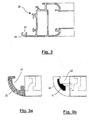
- Figure 3 shows, purely by way of example, a cross-section through a section 20 on which the component 1 of the invention may be mounted. Reference should also be made to Figures 3a, 3b, 4 and 5 in order to understand the steps for mounting the component 1 and its advantages.
- the component 1 is then introduced (arrow A in Figure 4) by inserting the engaging shank 11 into the associated seat 21 of the first section 20.
- the cross-section of the engaging shank 11 is also shown in black in Figure 3b.
- the tooth 10 is forced to engage with the seat 21 of the second section 20.
- the shape of the tooth 10 prevents it from coming out.
- the cavity 21 is designed so as to occupy only a small part of the seal-receiving seat 23, thus allowing the simultaneous use of a continuous seal 25.
- the shape of the component 1 allows the introduction of a continuous contact seal 25 which is not cut at the corner of the leaf.
- the person skilled in the art will recognize that this characteristic feature also arises from the fact that the head 2 of the component 1 is not a solid component, but forms a rounded internal surface and a shelf 9 which extends both towards the tooth 10 and towards the shank 11.
- the free seat 23 for the contact seal 25 is shown in Figure 3b. From Figure 3b it will also be understood that the shank 11 is relatively thin.
- the seal 25 is shown in Figure 5 before being inserted into its seat.
- the component 1 according to the invention may be made of plastic, for example nylon or ABS. Alternatively, it may also advantageously be made of metallic material such as pressure-cast aluminium or zamak.
Landscapes
- Engineering & Computer Science (AREA)
- Civil Engineering (AREA)
- Structural Engineering (AREA)
- Securing Of Glass Panes Or The Like (AREA)
- Vessels And Coating Films For Discharge Lamps (AREA)
- Joining Of Corner Units Of Frames Or Wings (AREA)
Abstract
Description
- The present invention relates to the sector of aluminium door or window frames and in particular relates to a component able to form a rounded corner in a leaf. The invention also relates to a leaf comprising such a component.
- For decades aluminium door and window frames made by suitably assembling portions of sections have been known. Windows, doors or the like in particular are made by assembling together portions of sections so as to form a kind of rectangular or square frame. The section portions are generally cut at 45° so that, once assembled, they form a right-angled corner with a sharp edge.
- Right-angled corners thus formed pose a problem for two main reasons.
- Firstly, right-angled corners with a sharp edge are dangerous and may cause injury. In fact, in particular in the case of windows, it is quite frequent for persons to knock against the sharp edge formed by the right-angled corner and hurt themselves. Children are most exposed to this danger, but adults may also inadvertently bang their head or other part of the body against the corner when standing up from a bent down position.
- The only solution to this problem known to the Applicant consists in an angular accessory which is glued to the frame at the sharp right-angled corner. This accessory is considered to be too voluminous, having dimensions of about 2.0 x 2.0 cm, is unattractive and in any case cannot ensure total safety. In fact, with time it tends to become detached from the leaf or is removed by the user precisely because it is considered to be unattractive.
- Secondly, the contact seal, which ensures the sealing action between the frame and the leaf, is cut at the right-angled corner. Often the seal is not cut precisely. In any case, an undesirable gap forms between one section of the seal and the other one. A not insignificant amount of heat is lost through this gap.
-
EP 0 448 520 A discloses a process for making casings by means of metal structural shapes. -
US 4 636 105 A discloses a corner pieces for frames. - The object of the present invention is to overcome the abovementioned problems and provide a component able to form a rounded corner in a leaf of a door or window frame, in particular in a leaf of an aluminium door or window frame.
- According to a first aspect, a component suitable for forming a corner with a rounded edge in a leaf of a door or window frame is provided, said corner being formed by a first section and by a second section. The component comprises: a shell-like head with a rounded external surface and an internal surface; a first side surface and a second side surface which are substantially perpendicular to each other; and a shank which extends from said second side surface, wherein said shank is configured for engaging in a corresponding seat of the first section which forms the corner. The component further comprises a snap-engaging tooth extending from said first side surface, said tooth being configured for engaging inside a corresponding seat of the second section which forms the corner.
- The tooth has preferably a length which increases in the direction towards the external surface.
- The internal surface is preferably concave and curved.
- According to a preferred embodiment, the external surface is a portion of a spherical surface.
- According to another aspect, a leaf of an aluminium door or window frame is provided, said leaf comprising at least two portions of a section assembled to form a corner and a component as described above.
- Advantageously, the component according to the present invention has small dimensions and therefore is not very visible and does not affect significantly the aesthetic appearance of the door or window frame.
- Advantageously it may be stably fixed to at least one section portion and may not be removed after assembly of the leaf.
- Another important advantage of the component according to the present invention is that it enables a continuous and uninterrupted contact seal to be provided in the corner.
- A detailed description of the invention is now provided, purely by way of a non-limiting example, to be read with reference to the accompanying illustrations in which:
- Figure 1 shows an enlarged axonometric view of the component for a rounded corner according to the present invention;
- Figures 2a, 2b and 2c are three plan views of the component according to Figure 1;
- Figure 3 shows a cross-sectional view of a section with which the component according to the invention may be associated;
- Figure 3a shows an enlarged detail of the section according to Figure 3, without the component according to the invention;
- Figure 3b shows an enlarged detail of the section according to Figure 3, with the component according to the invention;
- Figure 4 shows an axonometric view of a leaf corner on which the component according to the invention is being mounted; and
- Figure 5 shows the corner according to Figure 4 with the component according to the invention mounted and into which the contact seal is being inserted.
- An embodiment of the
component 1 able to form a rounded corner in a frame leaf, in particular in a leaf of an aluminium door or window frame, according to the invention, is shown in Figures 1, 2a, 2b and 2c. Thecomponent 1 comprises arounded head 2. Conveniently, thehead 2 substantially is in the form of a hemisphere segment. In particular, it has the form of a quarter segment of a hemisphere. By way of example, thehead 2 of thecomponent 1 is substantially shaped as a quarter of a hemisphere having a radius of about 5.0 mm. - The
head 2 is substantially shell-shaped and defines an externalrounded surface 3, an internal rounded surface 4, anupper edge surface 5, apointed end 6, afirst side surface 7 and asecond side surface 8. The first and thesecond side surfaces shelf 9 is provided between theupper surface 5 and thepointed end 6. The first and thesecond side surfaces component 1 is mounted, rest against the two sections. - A snap-
engaging tooth 10 projects from thefirst side surface 7, said tooth being able to lock thecomponent 1 to one side of the corner of the door or window frame leaf. The snap-engaging tooth 10 forms an extension of theshelf 9. The snap-engaging tooth 10, in order to favour mounting of thecomponent 1, has a length which increases from thepointed end 6 to theexternal surface 3. This can be clearly seen in Figure 2c. Basically, thetooth 10 defines an inclined surface. - An
engaging connection shank 11 with a curved cross-section visible in Figures 1 and 2a projects from thesecond side surface 8. Theengaging shank 11 defines a surface 11' which forms an extension of theshelf 9. In any case, the cross-sectional shape of theengaging shank 11 is determined by the shape of acorresponding seat 21 in the section 20 (Figure 3) with which the corner of a frame leaf will be formed. - Figure 3 shows, purely by way of example, a cross-section through a
section 20 on which thecomponent 1 of the invention may be mounted. Reference should also be made to Figures 3a, 3b, 4 and 5 in order to understand the steps for mounting thecomponent 1 and its advantages. - In order to be able to mount the
component 1 on the first andsecond section portion 20, recessing, shearing or milling of the corner is performed. This machining operation is performed in a known manner prior to assembling together the two section portions or after the two section portions have been assembled. The leaf corner according to Figure 4 is ready to receive thecomponent 1 according to the invention. The triangular part to be eliminated (by means of shearing, milling or other similar machining operation) is indicated by thereference number 22 and is coloured grey in Figure 3a. - The
component 1 is then introduced (arrow A in Figure 4) by inserting theengaging shank 11 into the associatedseat 21 of thefirst section 20. The cross-section of theengaging shank 11 is also shown in black in Figure 3b. By further forcing theengaging shank 11 into itsseat 21, thetooth 10 is forced to engage with theseat 21 of thesecond section 20. The shape of thetooth 10 prevents it from coming out. - The
cavity 21 is designed so as to occupy only a small part of the seal-receivingseat 23, thus allowing the simultaneous use of acontinuous seal 25. In other words, conveniently, the shape of thecomponent 1 allows the introduction of acontinuous contact seal 25 which is not cut at the corner of the leaf. In particular, the person skilled in the art will recognize that this characteristic feature also arises from the fact that thehead 2 of thecomponent 1 is not a solid component, but forms a rounded internal surface and ashelf 9 which extends both towards thetooth 10 and towards theshank 11. Thefree seat 23 for thecontact seal 25 is shown in Figure 3b. From Figure 3b it will also be understood that theshank 11 is relatively thin. Finally, theseal 25 is shown in Figure 5 before being inserted into its seat. - The
component 1 according to the invention may be made of plastic, for example nylon or ABS. Alternatively, it may also advantageously be made of metallic material such as pressure-cast aluminium or zamak. - From an aesthetic point of view, it may also be coloured with one colour or so as to imitate the grain in wood or provide a marble effect.
Claims (5)
- Component (1) configured for forming a corner with a rounded edge in a leaf of a door or window frame, said corner being formed by a first section (20) and by a second section (20), said component (1) comprising: a shell-like head (2) with a rounded external surface (3) and an internal surface (4); a first side surface (7) and a second side surface (8) which are substantially perpendicular to each other; and a shank (11) which extends from said second side surface (8), wherein said shank (11) is configured for engaging in a corresponding seat (21) of the first section (20) which forms the corner, characterized in that said component further comprises a snap-engaging tooth (10) extending from said first side surface (7), said tooth (10) being configured for engaging inside a corresponding seat (21) of the second section (20) which forms the corner.
- Component (1) according to Claim 1, characterized in that said tooth (10) has a length which increases in the direction towards the external surface (3).
- Component (1) according to any one of the preceding claims, characterized in that said internal surface (4) is concave and curved.
- Component (1) according to any one of the preceding claims, characterized in that said external surface (3) is a portion of a spherical surface.
- Leaf of an aluminium door or window frame comprising at least two portions of a section (20) which are assembled so as to form a corner, and a component (1) according to any one of the preceding claims.
Applications Claiming Priority (1)
| Application Number | Priority Date | Filing Date | Title |
|---|---|---|---|
| ITMI20060071 ITMI20060071A1 (en) | 2006-01-18 | 2006-01-18 | ELEMENT TO FORM A ROUNDED CORNER IN AN ALUMINUM WINDOW |
Publications (1)
| Publication Number | Publication Date |
|---|---|
| EP1811115A1 true EP1811115A1 (en) | 2007-07-25 |
Family
ID=36609513
Family Applications (1)
| Application Number | Title | Priority Date | Filing Date |
|---|---|---|---|
| EP07075045A Withdrawn EP1811115A1 (en) | 2006-01-18 | 2007-01-15 | Component for forming a rounded corner in a leaf of an aluminium door or window frame |
Country Status (2)
| Country | Link |
|---|---|
| EP (1) | EP1811115A1 (en) |
| IT (1) | ITMI20060071A1 (en) |
Cited By (3)
| Publication number | Priority date | Publication date | Assignee | Title |
|---|---|---|---|---|
| FR2945592A1 (en) * | 2009-05-15 | 2010-11-19 | Profils Systemes | ASSEMBLY IN CUT RIGHT. |
| ITFI20100115A1 (en) * | 2010-05-25 | 2011-11-26 | Sealt S R L | "CORNER PORTION OF WINDOW FRAME AND WINDOW FRAME WITH SUCH CORNER PORTION" |
| CN109403799A (en) * | 2018-12-06 | 2019-03-01 | 广东津美家居用品有限公司 | A kind of inwardly opened window door |
Citations (3)
| Publication number | Priority date | Publication date | Assignee | Title |
|---|---|---|---|---|
| US4636105A (en) * | 1983-05-05 | 1987-01-13 | Johansson Gert A | Corner piece for frames |
| EP0448520A1 (en) * | 1990-03-06 | 1991-09-25 | Luciano Didaco Turi | Process for making casings by means of metal structural shapes |
| DE9207308U1 (en) * | 1992-05-29 | 1992-09-03 | Memory Fotolabor und -Vertriebsgesellschaft mbH, 7174 Ilshofen | Picture Frame |
-
2006
- 2006-01-18 IT ITMI20060071 patent/ITMI20060071A1/en unknown
-
2007
- 2007-01-15 EP EP07075045A patent/EP1811115A1/en not_active Withdrawn
Patent Citations (3)
| Publication number | Priority date | Publication date | Assignee | Title |
|---|---|---|---|---|
| US4636105A (en) * | 1983-05-05 | 1987-01-13 | Johansson Gert A | Corner piece for frames |
| EP0448520A1 (en) * | 1990-03-06 | 1991-09-25 | Luciano Didaco Turi | Process for making casings by means of metal structural shapes |
| DE9207308U1 (en) * | 1992-05-29 | 1992-09-03 | Memory Fotolabor und -Vertriebsgesellschaft mbH, 7174 Ilshofen | Picture Frame |
Cited By (4)
| Publication number | Priority date | Publication date | Assignee | Title |
|---|---|---|---|---|
| FR2945592A1 (en) * | 2009-05-15 | 2010-11-19 | Profils Systemes | ASSEMBLY IN CUT RIGHT. |
| EP2253793A1 (en) * | 2009-05-15 | 2010-11-24 | Profils Systèmes | Straight-cut assembly |
| ITFI20100115A1 (en) * | 2010-05-25 | 2011-11-26 | Sealt S R L | "CORNER PORTION OF WINDOW FRAME AND WINDOW FRAME WITH SUCH CORNER PORTION" |
| CN109403799A (en) * | 2018-12-06 | 2019-03-01 | 广东津美家居用品有限公司 | A kind of inwardly opened window door |
Also Published As
| Publication number | Publication date |
|---|---|
| ITMI20060071A1 (en) | 2007-07-19 |
Similar Documents
| Publication | Publication Date | Title |
|---|---|---|
| US20020148165A1 (en) | Mounting mechanism for shutters having movable louvers | |
| US20110000145A1 (en) | Decorative molding | |
| EP3377720B1 (en) | Joint for the angular connection of hollow profile members and method using such joint | |
| US4644721A (en) | Grille fastener system and method of using the same | |
| US20070017157A1 (en) | Silding door | |
| US6230456B1 (en) | Window insert fastener | |
| US5423510A (en) | Decorative covering for shelf brackets and standards | |
| CA2822831C (en) | Screen attachment method for lineals | |
| CA2270270A1 (en) | Panel door with large width gasketless frame | |
| CA2314984A1 (en) | Log facade | |
| EP3153716B1 (en) | Joining device with leveller for external panels of parts of furniture and furnishing items | |
| USD491278S1 (en) | Acrylic window insert for a garage door | |
| WO1991002868A1 (en) | House trim panels for use with siding | |
| CN111335776A (en) | Mounting structure of assembled door pocket | |
| EP0306129B1 (en) | Glazing bead element for a window assembly and window assembly | |
| USD448090S1 (en) | Insert trim set for garage door windows | |
| US20120066995A1 (en) | Custom shutter | |
| GB2408769A (en) | Safety door and frame assembly | |
| KR102137685B1 (en) | Door frame for furniture | |
| EP0752512A1 (en) | Door case and mouldings for same | |
| ITMI20060071A1 (en) | ELEMENT TO FORM A ROUNDED CORNER IN AN ALUMINUM WINDOW | |
| KR100385174B1 (en) | Soundproof and fireproof door curved with gourd shape | |
| JP3939897B2 (en) | Exterior wall decorative material construction method | |
| WO2005121483A1 (en) | Adjustable coor frame | |
| WO2002034085A1 (en) | Panel edging system |
Legal Events
| Date | Code | Title | Description |
|---|---|---|---|
| PUAI | Public reference made under article 153(3) epc to a published international application that has entered the european phase |
Free format text: ORIGINAL CODE: 0009012 |
|
| AK | Designated contracting states |
Kind code of ref document: A1 Designated state(s): AT BE BG CH CY CZ DE DK EE ES FI FR GB GR HU IE IS IT LI LT LU LV MC NL PL PT RO SE SI SK TR |
|
| AX | Request for extension of the european patent |
Extension state: AL BA HR MK YU |
|
| 17P | Request for examination filed |
Effective date: 20070913 |
|
| AKX | Designation fees paid |
Designated state(s): AT BE BG CH CY CZ DE DK EE ES FI FR GB GR HU IE IS IT LI LT LU LV MC NL PL PT RO SE SI SK TR |
|
| GRAP | Despatch of communication of intention to grant a patent |
Free format text: ORIGINAL CODE: EPIDOSNIGR1 |
|
| STAA | Information on the status of an ep patent application or granted ep patent |
Free format text: STATUS: THE APPLICATION IS DEEMED TO BE WITHDRAWN |
|
| 18D | Application deemed to be withdrawn |
Effective date: 20120905 |