EP1808905B1 - Method and apparatus for regulation of electrical power - Google Patents
Method and apparatus for regulation of electrical power Download PDFInfo
- Publication number
- EP1808905B1 EP1808905B1 EP06000722A EP06000722A EP1808905B1 EP 1808905 B1 EP1808905 B1 EP 1808905B1 EP 06000722 A EP06000722 A EP 06000722A EP 06000722 A EP06000722 A EP 06000722A EP 1808905 B1 EP1808905 B1 EP 1808905B1
- Authority
- EP
- European Patent Office
- Prior art keywords
- cooling agent
- internal container
- container
- superconducting
- mass flow
- Prior art date
- Legal status (The legal status is an assumption and is not a legal conclusion. Google has not performed a legal analysis and makes no representation as to the accuracy of the status listed.)
- Expired - Lifetime
Links
Images



Classifications
-
- H—ELECTRICITY
- H10—SEMICONDUCTOR DEVICES; ELECTRIC SOLID-STATE DEVICES NOT OTHERWISE PROVIDED FOR
- H10N—ELECTRIC SOLID-STATE DEVICES NOT OTHERWISE PROVIDED FOR
- H10N60/00—Superconducting devices
- H10N60/30—Devices switchable between superconducting and normal states
-
- Y—GENERAL TAGGING OF NEW TECHNOLOGICAL DEVELOPMENTS; GENERAL TAGGING OF CROSS-SECTIONAL TECHNOLOGIES SPANNING OVER SEVERAL SECTIONS OF THE IPC; TECHNICAL SUBJECTS COVERED BY FORMER USPC CROSS-REFERENCE ART COLLECTIONS [XRACs] AND DIGESTS
- Y10—TECHNICAL SUBJECTS COVERED BY FORMER USPC
- Y10S—TECHNICAL SUBJECTS COVERED BY FORMER USPC CROSS-REFERENCE ART COLLECTIONS [XRACs] AND DIGESTS
- Y10S505/00—Superconductor technology: apparatus, material, process
- Y10S505/825—Apparatus per se, device per se, or process of making or operating same
- Y10S505/85—Protective circuit
Definitions
- the invention relates to methods and apparatuses for regulation of the electrical power.
- a method and apparatus for regulating electric power also referred to as current limiters or fault current limiters, are known for example from US 5,379,020 .
- the method comprises transporting an electrical current through a superconducting member exhibiting a capability of quenching at the electrical current exceeding a threshold value, transporting an additional electrical current through a metallic member coupled to the superconducting member, filling a thermally insulated and tight internal container with a portion of a liquid fraction of a cooling agent, liquid nitrogen, and a portion of a gas fraction (nitrogen) of the cooling agent, cooling the superconducting member and the metallic member by their direct contact with the liquid fraction of the cooling agent in the internal container and providing a mass exchange of the cooling agent between the internal container and an external container, in order to refill the internal container up to operation level.
- An apparatus for realizing this method comprises:
- Such method and apparatus can be used to regulate electrical power, in particular to regulate the current in an external electrical circuit to which the device has been coupled.
- the external circuit may be protected against overcurrents.
- these types of current limiting devices suffer from the disadvantages that the reaction time of the apparatus is relatively long and is insufficient for some applications.
- local overloads may occur in the superconducting member at current overloads. These hot spots may limit a lifetime of the superconductor and, in extreme cases, can lead to failure of the superconductor member and the apparatus.
- the superconducting current limiter in EP 1 217 708 A1 utilizes a cooling liquid without a phase transition above operation temperature. An undesired evaporation of the cooling agent is avoided in the limiting case. However, the disadvantage of a long reaction time persists.
- a further object of the present invention is to increase the lifetime of the apparatus.
- a further object of the invention is to provide apparatus which can be cost-efficiently produced.
- a method for regulation of electrical power comprises:
- the exchange of the cooling agent is controlled
- the superconductor During normal operation, the superconductor is in the superconducting, i.e. a low resistance state. When a threshold current is exceeded, the superconductor rapidly enters a highly resistive state or quenches, thus regulating the current.
- the method according to the invention controls the quenching of the superconductor and consequently regulates the electric power by controlling the cooling power delivered by the cooling agent to the superconductor member during an overcurrent or fault current condition.
- the cooling power of the cooling agent is varied with time, in particular after the start of an overcurrent or fault condition.
- the exchange of the cooling agent between the external container and internal container in which the superconductor member is positioned is controlled in order to control the quenching characteristics of the superconductor member.
- the exchange of the cooling agent is controlled by controlling the following parameters after the initial stages of the quenching of the superconductor.
- the initial quenching stage may occur at localized regions or hot spots.
- the following parameters are controlled with a desired time sequence in order to achieve the desired quenching characteristics of the superconductor and, therefore, control the regulation of the electric power or current in an external circuit to which apparatus used to perform the method is coupled: the mass flow of the cooling agent which is output from the internal container, and an instantaneous pressure in the internal container with an interruption of a predetermined duration.
- an interruption of a predetermined duration refers to a time delay between the control of the mass flow of the cooling agent and the instantaneous pressure in the internal container and, in particular, between the initiation of the control of the mass flow of the cooling agent and the instantaneous pressure in the internal container.
- the superconducting member when the superconducting member starts to enter the highly resistive state, localized isolated regions of the superconductor may enter the highly resistive state, i.e. quench, first. This results in boiling of the liquid cooling agent.
- This increase in pressure can be controlled by closing the internal container to reduce or prevent the mass flow of cooling agent from the external container to the internal container. The closing of the internal container leads to an increase in pressure within the internal container and an increase in the boiling temperature of the cooling agent. The cooling power delivered by the cooling agent to the superconducting member is reduced which leads to a fast quench of the entire superconductor.
- This method has the advantage that the reaction time of the regulation of the electrical power in the external circuit is reduced. Furthermore, since the entire superconductor is encouraged to quench rapidly, this suppresses the influence of localized hot spots which leads to an increase in the lifetime of the superconducting ember and the electrical device.
- the mass exchange is enabled when the instantaneous pressure in the internal container exceeds the pressure in the external container by a pre-determined value. Cooling agent is allowed to enter the internal container from the external container to increase the cooling power.
- the mass exchange is substantially reduced after the mass flow that is output from the internal container exceeds a pre-determined level. This regulates the temperature and cooling power within the internal container.
- the mass exchange is enabled after the predetermined time delay after the instantaneous pressure in the internal container reaches higher values compared to the pressure in the external container. This enables a reduction in the cooling power and an increase in the boiling temperature of the cooling agent for a desired time interval.
- An apparatus for regulation of electrical power according to the invention comprises:
- the means for the mass exchange of the cooling agent comprise:
- the apparatus for regulating electric power, when in operation, is coupled to an external circuit which is to be regulated. This may be carried out in a number of ways which are known in the art.
- the mass flow controller enables the mass flow of the cooling agent from the external container to the internal container in which at least the superconducting member is positioned to be controlled so as to control the cooling power of the cooling agent in the internal container and consequently to control the quenching of the superconducting member and regulate the electrical power or current in the external circuit to which the apparatus is coupled.
- the controller of the instantaneous pressure enables the pressure within the internal container to be regulated.
- the controller may be closed, for example after an overcurrent condition is detected as an increase in pressure within the internal container, in order to increase the pressure within the container and reduce the cooling power. This encourages the rapid quenching of the entire superconductor member and increases the reaction time of the apparatus. If, for example, the pressure exceeds a pre-determined value the controller which may comprise a valve for example can be opened and the pressure in the internal container reduced. The boiling temperature of the cooling agent can, therefore, be controlled as desired.
- the delay circuit may provide a predetermined delay between the closing of the valve which controls the instantaneous pressure of the internal container and the opening of the mass flow controller which allows the input of the cooling agent from the external container to the internal container and a reduction in the boiling temperature of the cooling agent within the internal container.
- the cooling power of the cooling agent within the internal container is, therefore, improved.
- the delay circuit therefore, allows the cooling power of the cooling agent in the internal container to be reduced for a predetermined time interval.
- the means for controlling the mass exchange of the cooling agent and the internal container therefore, provide a means by which the quenching of the superconductor member can be controlled and, consequently, provides a means by which the regulation or limiting of the current in an external circuit to which the apparatus is attached may be controlled.
- the mass flow controller comprises a transient member that is capable of transporting the cooling agent and which provides an increased differential pressure between the internal container and the external container after each event of increased mass flow.
- the transient member may be provided as a nozzle.
- the transient member may be provided as an externally controllable valve.
- the controller of the instantaneous pressure may comprise a further valve which is a normally closed valve.
- the mass flow controller may comprise two or more transient members which may be independently controlled to provide a finer control of the mass flow of e cooling agent from the external container to the internal container.
- the delay circuit may provide the opening of the externally controlled valve.
- a triggering pulse may be provided by the time delay circuit after a predetermined time interval which is delivered to the transient member so that the cooling agent is delivered into the internal container.
- a triggering pulse may be sent to an actuator so that a valve opens and the mass flow of cooling agent is enabled.
- the metallic member is at least partly provided by at least one metallic wall of the internal container.
- the metallic member is coupled to the superconducting member by electrical joints or through a common part of magnetic flux.
- the apparatus and method of the invention are, therefore, suitable for use with both inductive and resistive electric power regulators.
- the superconducting member comprises a superconducting material which is defined as material which below a critical temperature, a critical magnetic field and a critical current exhibits superconductivity.
- superconductors are Nb 3 Sn and NbTi which are commonly referred to low temperature superconductors and ReBa 2 Cu 3 O 7-x , where Re is one or more rare earth elements such as Y, Bi 2 Sr 2 CaCu 2 O x and Bi(Pb) 2 Sr 2 Ca 2 Cu 3 O x which are commonly referred to as high temperature superconductors.
- the cooling agent is chosen depending on the critical temperature of the superconducting member.
- For superconducting members comprising ReBa 2 Cu 3 O 7-x Bi 2 Sr 2 CaCu 2 O x and Bi(Pb) 2 Sr 2 Ca 2 Cu 3 O 10 liquid nitrogen may be conveniently used as the cooling agent.
- the superconducting member may be provided in a number of forms, for example a cylinder of a superconductor, a coating of a superconductor on a substrate, which may be non-electrically conducting such as a ceramic, or in the form of a coating or film on a flexible metallic tape substrate. One to two sides of the tape may be coated with the superconducting phase.
- the superconductor member may comprise biaxially textured ReBa 2 Cu 3 O 7-x tape.
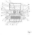
- Fig. 1 depicts a schematic view of the first embodiment of the apparatus according to the present invention.
- the apparatus comprises:
- the mass flow controller comprises a transient member 9, 10, 20-23, 26 that is capable of transporting the cooling agent and provides an increased differential pressure between the internal container 4 and the external container 7 after each event of increased mass flow.
- the transient member is provided as an externally controlled valve, based on a ball 20 moving between position 20 and position 21, and an offset positioner 22.
- the controller of the instantaneous pressure comprises a normally closed additional valve 30 , where a ball 32 is elastically pressed by a spring 33 to a nozzle 31 .
- the additional valve may also be connected to an upper part of the external container 7, at a position which is above the level of the liquid cooling agent 8.
- the delay circuit 25 provides opening of the externally controlled valve 20, 20-22 using a triggering signal produced by the moving ball 20.
- This pulsed signal is amplified by an amplifier 23, and delivered via connection 24 to the delay circuit 25. Delayed pulse is delivered to an actuator 26 which provides a return of the ball to the position 20.
- the apparatus construction also comprises two electrical feedthroughs 5 which deliver electrical current to the superconducting member 1 and the metallic member 2.
- a method employed for operation of the apparatus of Fig. 1 comprises:
- the transporting of the current through the superconducting member 1 and transporting of the additional current trough the metallic member 2 is provided by sharing the current delivered by electrical feedthroughs 5 at the jointing discs 3.
- the filling of the internal container 4 follows through the external container 7 which is filled with the liquid cooling agent, namely liquid nitrogen in the considered example.
- the liquid cooling agent namely liquid nitrogen in the considered example.
- the agent starts to fill the internal container 4 through the pipe 9 and open valve 10.
- Filling of the internal container 4 lasts until the level 40 of liquid cooling agent is high enough, so that only a small rest volume 41, typically, of several cubic centimetres, is filled with a gas fraction 31 of the cooling agent.
- the cooling of the superconducting member 1 occurs though a direct contact with the liquid fraction 6 of the cooling agent in the internal container 4. This is provided using a number of small through-openings 2a in the outer walls of the metallic member 2 which allow the liquid cooling agent to enter to the interior cavity of the metallic member 2 where the superconducting member 1 is located. Direct surface to surface cooling of the superconducting member 1 is provided.
- the superconducting member 1 When the electrical current in the superconducting member 1 exceeds a threshold value the superconducting member 1 starts to quench and enters a highly resistive state. During the first moments, the quenching occurs at a number of local spots. As a result of the generation of Joule's heat in the superconducting member 1 and in the metallic member 2 boiling of the liquid cooling agent intensifies, and the mass flow of the cooling agent which is output from the internal container 4 rapidly increases. This causes a closing of the externally controlled valve 10. As the volume 41 of the internal container 4 occupied by the gas portion of the cooling phase is rather small, the pressure in the internal container 4 rapidly grows.
- the upper limit of this pressure is predetermined by the controller 30-35 of an instantaneous pressure.
- the normally closed additional valve 30 opens, so that the pressure drops down.
- the instantaneous pressure in the container slightly oscillates.
- a triggering pulse initially triggered by the ball 20 and the offset positioner 22, is delivered to the actuator 26 which provides a return of the ball to the initial position 20.
- Externally controlled valve opens and the pressure in the container 4 equalizes with the pressure in the external container 7 during a certain time period.
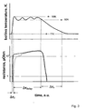
- ⁇ f denotes a time-width of the front of pressure pulse
- ⁇ delay denotes a delay time predetermined by a delay circuit
- ⁇ r denotes a time of pressure release that occur at the last stage of operation circle of the externally controlled valve 10, respectively.
- cooling power delivered by the cooling agent to the superconducting member 1 significantly reduces during the pressure pulse when the instantaneous pressure may reach 2 bar to 6 bar. This leads to a fast quench of the entire superconductor, suppressing the influence of "hot spots”. Finally this results in shortage of the reaction time of regulation of electrical power.
- Fig. 3 The variation with time of the boiling temperature of the cooling agent 6 and the resistance of both the superconducting member 1 and the metallic member 2 electrically jointed in parallel are illustrated by plots depicted in Fig. 3 .
- Denotations in Fig. 3 are the same as in Fig. 2 ; solid curves correspond to the present invention, a spot curve corresponds to the known state of art.
- the reaction time which is provided by the present method and apparatus are significantly shorter than those provided by apparatus and methods in which the exchange of the cooling agent is not controlled according to the invention.
- the reaction time is reduced using the method and apparatus of the invention by a factor from 5 to 20 leading to absolute values of the reaction time of the order of 100 ⁇ s.
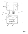
- Fig. 4 depicts a schematic view of the second embodiment of the apparatus according to the present invention.
- the apparatus comprises:
- the delay circuit is provided by the same transient member 60 which comprises the mass flow controller.
- the transient member 60 is provided as a nozzle with a sufficiently small cross-section in order to provide a pulse of pressure in the internal container 54 during the time required for power regulation (i.e. power limitation).
- the controller of the instantaneous pressure comprises a normally closed additional valve 70, with self return function.
- the additional valve may also be connected to an upper part of the external container 57, at a position which is above the level of the liquid cooling agent 58.
- Fig. 5 depicts a schematic view of the third embodiment of the apparatus according to the present invention.
- the apparatus comprises in this case the same components as the apparatus shown in Fig. 1 with the following modifications:
- the apparatus is operating in the same way as the apparatus of Fig. 1 with a difference that the controlling of mass flow is provided by two channels comprising two independent valves 10 and 10a.
- the apparatus and the method are capable of more precise controlling of mass flow compared to the embodiment of Fig. 1 .
- a further 30% reduction in the reaction time compared to the embodiment of Fig. 1 can be provided.
- the reaction time of the apparatus of Fig. 5 was 70 microseconds.
- Fig. 6 reveals a schematic view of the fourth embodiment of the apparatus according to the present invention.
- the apparatus comprises the same components as the apparatus shown in Fig. 5 with the following modifications:
- the difference in method of operation compared to the method of Fig. 5 follows mainly from the employed magnetic coupling of the superconducting member 11 so that the current of an ac circuit to be regulated regarding electrical power is delivered to the primary spool 120 through the end wires 121.
Landscapes
- Containers, Films, And Cooling For Superconductive Devices (AREA)
- Emergency Protection Circuit Devices (AREA)
- Control Of Eletrric Generators (AREA)
- Control Of Motors That Do Not Use Commutators (AREA)
- Electrical Discharge Machining, Electrochemical Machining, And Combined Machining (AREA)
Abstract
Description
- The invention relates to methods and apparatuses for regulation of the electrical power.
- A method and apparatus for regulating electric power, also referred to as current limiters or fault current limiters, are known for example from
US 5,379,020 . The method comprises transporting an electrical current through a superconducting member exhibiting a capability of quenching at the electrical current exceeding a threshold value, transporting an additional electrical current through a metallic member coupled to the superconducting member, filling a thermally insulated and tight internal container with a portion of a liquid fraction of a cooling agent, liquid nitrogen, and a portion of a gas fraction (nitrogen) of the cooling agent, cooling the superconducting member and the metallic member by their direct contact with the liquid fraction of the cooling agent in the internal container and providing a mass exchange of the cooling agent between the internal container and an external container, in order to refill the internal container up to operation level. - An apparatus for realizing this method comprises:
- a superconducting member exhibiting a capability of quenching at an electrical current exceeding a threshold value,
- a metallic member coupled to the superconducting member,
- a thermally insulated and tight internal container filled with a portion of a liquid fraction of a cooling agent and a portion of a gas fraction of the cooling agent,
- the internal container being capable of providing a cooling of the superconducting member and the metallic member by their direct contact with the liquid fraction of the cooling agent and
- means for providing a mass exchange of the cooling agent between the internal container and an external container
- Such method and apparatus can be used to regulate electrical power, in particular to regulate the current in an external electrical circuit to which the device has been coupled. The external circuit may be protected against overcurrents. However, these types of current limiting devices suffer from the disadvantages that the reaction time of the apparatus is relatively long and is insufficient for some applications. Furthermore, local overloads (so called "hot spots") may occur in the superconducting member at current overloads. These hot spots may limit a lifetime of the superconductor and, in extreme cases, can lead to failure of the superconductor member and the apparatus.
- The superconducting current limiter in
EP 1 217 708 A1 - It is an object of the present invention to provide a method and an apparatus for regulation of electrical power which exhibits a short reaction time. A further object of the present invention is to increase the lifetime of the apparatus. A further object of the invention is to provide apparatus which can be cost-efficiently produced.
- The these objects are provided using a method with the features according to
claim 1 and apparatus with the features according toclaim 5. Advantageous improvements of the method are the subject matter ofclaims 2 to 4. Advantageous improvements of the apparatus are the subject matter ofclaims 6 to 13. - According to the present invention, a method for regulation of electrical power comprises:
- transporting an electrical current through a superconducting member exhibiting a capability of quenching at the electrical current exceeding a threshold value;
- transporting an additional electrical current through a metallic member coupled to the superconducting member;
- filling of a thermally insulated and enclosed internal container with a portion of a liquid fraction of a cooling agent and a portion of a gas fraction of the cooling agent;
- cooling of the superconducting member and the metallic member by their direct contact with the liquid fraction of the cooling agent in the internal container, and
- providing a mass exchange of the cooling agent between the internal container and an external container.
- The exchange of the cooling agent is controlled
- as a function of both
- a mass flow of the cooling agent which is output from the internal container, and
- an instantaneous pressure in the internal container
- with an interruption of a predetermined duration.
- During normal operation, the superconductor is in the superconducting, i.e. a low resistance state. When a threshold current is exceeded, the superconductor rapidly enters a highly resistive state or quenches, thus regulating the current. The method according to the invention, controls the quenching of the superconductor and consequently regulates the electric power by controlling the cooling power delivered by the cooling agent to the superconductor member during an overcurrent or fault current condition. In particular, the cooling power of the cooling agent is varied with time, in particular after the start of an overcurrent or fault condition.
- According to the invention, the exchange of the cooling agent between the external container and internal container in which the superconductor member is positioned is controlled in order to control the quenching characteristics of the superconductor member.
- The exchange of the cooling agent is controlled by controlling the following parameters after the initial stages of the quenching of the superconductor. The initial quenching stage may occur at localized regions or hot spots. According to the invention, the following parameters are controlled with a desired time sequence in order to achieve the desired quenching characteristics of the superconductor and, therefore, control the regulation of the electric power or current in an external circuit to which apparatus used to perform the method is coupled: the mass flow of the cooling agent which is output from the internal container, and an instantaneous pressure in the internal container with an interruption of a predetermined duration. In this context, an interruption of a predetermined duration refers to a time delay between the control of the mass flow of the cooling agent and the instantaneous pressure in the internal container and, in particular, between the initiation of the control of the mass flow of the cooling agent and the instantaneous pressure in the internal container.
- For example, when the superconducting member starts to enter the highly resistive state, localized isolated regions of the superconductor may enter the highly resistive state, i.e. quench, first. This results in boiling of the liquid cooling agent. This increase in pressure can be controlled by closing the internal container to reduce or prevent the mass flow of cooling agent from the external container to the internal container. The closing of the internal container leads to an increase in pressure within the internal container and an increase in the boiling temperature of the cooling agent. The cooling power delivered by the cooling agent to the superconducting member is reduced which leads to a fast quench of the entire superconductor.
- This method has the advantage that the reaction time of the regulation of the electrical power in the external circuit is reduced. Furthermore, since the entire superconductor is encouraged to quench rapidly, this suppresses the influence of localized hot spots which leads to an increase in the lifetime of the superconducting ember and the electrical device.
- In an embodiment of the invention, the mass exchange is enabled when the instantaneous pressure in the internal container exceeds the pressure in the external container by a pre-determined value. Cooling agent is allowed to enter the internal container from the external container to increase the cooling power.
- In a further embodiment of the invention, the mass exchange is substantially reduced after the mass flow that is output from the internal container exceeds a pre-determined level. This regulates the temperature and cooling power within the internal container.
- In a further embodiment of the invention, the mass exchange is enabled after the predetermined time delay after the instantaneous pressure in the internal container reaches higher values compared to the pressure in the external container. This enables a reduction in the cooling power and an increase in the boiling temperature of the cooling agent for a desired time interval.
- An apparatus for regulation of electrical power according to the invention comprises:
- a superconducting member exhibiting a capability of quenching at the electrical current exceeding a threshold value,
- a metallic member coupled to the superconducting member,
- a thermally insulated and tight internal container filled with a portion of a liquid fraction of a cooling agent and a portion of a gas fraction of the cooling agent,
- the internal container being capable to providing a cooling of the superconducting member and the metallic member by their direct contact with the liquid fraction of the cooling agent in and
- means for providing a mass exchange of the cooling agent between the internal container and an external container.
- The means for the mass exchange of the cooling agent comprise:
- a mass flow controller for the cooling agent which is output from the inner container;
- a controller of an instantaneous pressure in the internal container, and
- a delay circuit providing a pre-determined time-delay for mass flow controller operation.
- The apparatus for regulating electric power, when in operation, is coupled to an external circuit which is to be regulated. This may be carried out in a number of ways which are known in the art.
- The mass flow controller enables the mass flow of the cooling agent from the external container to the internal container in which at least the superconducting member is positioned to be controlled so as to control the cooling power of the cooling agent in the internal container and consequently to control the quenching of the superconducting member and regulate the electrical power or current in the external circuit to which the apparatus is coupled.
- The controller of the instantaneous pressure enables the pressure within the internal container to be regulated. The controller may be closed, for example after an overcurrent condition is detected as an increase in pressure within the internal container, in order to increase the pressure within the container and reduce the cooling power. This encourages the rapid quenching of the entire superconductor member and increases the reaction time of the apparatus. If, for example, the pressure exceeds a pre-determined value the controller which may comprise a valve for example can be opened and the pressure in the internal container reduced. The boiling temperature of the cooling agent can, therefore, be controlled as desired.
- The delay circuit may provide a predetermined delay between the closing of the valve which controls the instantaneous pressure of the internal container and the opening of the mass flow controller which allows the input of the cooling agent from the external container to the internal container and a reduction in the boiling temperature of the cooling agent within the internal container. The cooling power of the cooling agent within the internal container is, therefore, improved. The delay circuit, therefore, allows the cooling power of the cooling agent in the internal container to be reduced for a predetermined time interval.
- The means for controlling the mass exchange of the cooling agent and the internal container, therefore, provide a means by which the quenching of the superconductor member can be controlled and, consequently, provides a means by which the regulation or limiting of the current in an external circuit to which the apparatus is attached may be controlled.
- In an embodiment of the invention, the mass flow controller comprises a transient member that is capable of transporting the cooling agent and which provides an increased differential pressure between the internal container and the external container after each event of increased mass flow.
- The transient member may be provided as a nozzle. Alternatively, the transient member may be provided as an externally controllable valve.
- The controller of the instantaneous pressure may comprise a further valve which is a normally closed valve.
- The mass flow controller may comprise two or more transient members which may be independently controlled to provide a finer control of the mass flow of e cooling agent from the external container to the internal container.
- The delay circuit may provide the opening of the externally controlled valve. A triggering pulse may be provided by the time delay circuit after a predetermined time interval which is delivered to the transient member so that the cooling agent is delivered into the internal container. A triggering pulse may be sent to an actuator so that a valve opens and the mass flow of cooling agent is enabled.
- In an embodiment of the invention, the metallic member is at least partly provided by at least one metallic wall of the internal container.
- In a further embodiment of the invention, the metallic member is coupled to the superconducting member by electrical joints or through a common part of magnetic flux. The apparatus and method of the invention are, therefore, suitable for use with both inductive and resistive electric power regulators.
- The superconducting member comprises a superconducting material which is defined as material which below a critical temperature, a critical magnetic field and a critical current exhibits superconductivity. Examples of superconductors are Nb3Sn and NbTi which are commonly referred to low temperature superconductors and ReBa2Cu3O7-x, where Re is one or more rare earth elements such as Y, Bi2Sr2CaCu2Ox and Bi(Pb)2Sr2Ca2Cu3Ox which are commonly referred to as high temperature superconductors. The cooling agent is chosen depending on the critical temperature of the superconducting member. For superconducting members comprising ReBa2Cu3O7-x, Bi2Sr2CaCu2Ox and Bi(Pb)2Sr2Ca2Cu3O10 liquid nitrogen may be conveniently used as the cooling agent.
- The superconducting member may be provided in a number of forms, for example a cylinder of a superconductor, a coating of a superconductor on a substrate, which may be non-electrically conducting such as a ceramic, or in the form of a coating or film on a flexible metallic tape substrate. One to two sides of the tape may be coated with the superconducting phase. The superconductor member may comprise biaxially textured ReBa2Cu3O7-x tape.
- Methods and apparatus for regulation of the electrical power in accordance with the present invention will now be described, by way of example, with reference to the following accompanying figures:
-
Fig. 1 A schematic view of a first embodiment of the device according to the present invention; -
Fig. 2 Plots clarifying an operation of the method and apparatus according to the present invention; -
Fig. 3 Further plots clarifying an operation of the method and apparatus according to the present invention; -
Fig. 4 A schematic view of a second embodiment of the apparatus according to the present invention; -
Fig. 5 A schematic view of a third embodiment of the apparatus according to the present invention; -
Fig. 6 A schematic view of a fourth embodiment of the apparatus according to the present invention. -
Fig. 1 depicts a schematic view of the first embodiment of the apparatus according to the present invention. The apparatus comprises: - a
superconducting member 1 exhibiting a capability of quenching at an electrical current exceeding a threshold value, - a
metallic member 2 coupled to the superconducting member byjointing discs 3, - a thermally insulated and tight
internal container 4 filled with a cooling agent of which a portion of aliquid fraction 6 of a cooling agent and a portion of agas fraction 31 of the cooling agent, - the
internal container 4 being capable of providing a cooling of thesuperconducting member 1 and themetallic member 2 by their direct contact with theliquid fraction 6 of the cooling agent. In the apparatus ofFig. 1 , the superconducting member is positioned within the inner cavity of the metallic member. A number ofopenings 2a are provided in the metallic member which allow passage of theliquid cooling agent 6 into the cavity and enable direct contact between theliquid cooling agent 6 and thesuperconducting member 1, and - means 9, 10, 20-26 and 30, 34, 35 for providing a mass exchange of the cooling agent between the
internal container 4 and anexternal container 7. - These means for the mass exchange, according to the invention, comprise
- a
mass flow controller inner container 4, - a controller 30-35 of an instantaneous pressure in the
internal container 4, and - a
delay circuit 25 providing a pre-determined time-delay for mass flow controller operation. - The mass flow controller comprises a
transient member internal container 4 and theexternal container 7 after each event of increased mass flow. In the present embodiment the transient member is provided as an externally controlled valve, based on aball 20 moving betweenposition 20 andposition 21, and an offset positioner 22. - The controller of the instantaneous pressure comprises a normally closed
additional valve 30, where aball 32 is elastically pressed by aspring 33 to anozzle 31. The additional valve may also be connected to an upper part of theexternal container 7, at a position which is above the level of theliquid cooling agent 8. - The
delay circuit 25 provides opening of the externally controlledvalve 20, 20-22 using a triggering signal produced by the movingball 20. This pulsed signal is amplified by anamplifier 23, and delivered viaconnection 24 to thedelay circuit 25. Delayed pulse is delivered to anactuator 26 which provides a return of the ball to theposition 20. - The apparatus construction also comprises two
electrical feedthroughs 5 which deliver electrical current to thesuperconducting member 1 and themetallic member 2. - A method employed for operation of the apparatus of
Fig. 1 comprises: - transporting an electrical current through a
superconducting member 1 exhibiting a capability of quenching at the electrical current exceeding a threshold value, - transporting an additional electrical current through a
metallic member 2 coupled to thesuperconducting member 1, - filling of a thermally insulated and tight
internal container 4 with a portion of aliquid fraction 6 of a cooling agent and a portion of agas fraction 31 of the cooling agent, - cooling of the
superconducting member 1 and themetallic member 2 by their direct contact with theliquid fraction 6 of the cooling agent in theinternal container 4 and - providing a mass exchange of the cooling agent between the
internal container 4 and anexternal container 7. - a mass flow of the cooling agent which is output from the
inner container 4, - an instantaneous pressure in the
internal container 4, - a pre-determined time-delay.
- The transporting of the current through the
superconducting member 1 and transporting of the additional current trough themetallic member 2 is provided by sharing the current delivered byelectrical feedthroughs 5 at thejointing discs 3. - The filling of the
internal container 4 follows through theexternal container 7 which is filled with the liquid cooling agent, namely liquid nitrogen in the considered example. When level of the liquid cooling agent is sufficiently high, the agent starts to fill theinternal container 4 through thepipe 9 andopen valve 10. Filling of theinternal container 4 lasts until thelevel 40 of liquid cooling agent is high enough, so that only asmall rest volume 41, typically, of several cubic centimetres, is filled with agas fraction 31 of the cooling agent. - The cooling of the
superconducting member 1 occurs though a direct contact with theliquid fraction 6 of the cooling agent in theinternal container 4. This is provided using a number of small through-openings 2a in the outer walls of themetallic member 2 which allow the liquid cooling agent to enter to the interior cavity of themetallic member 2 where thesuperconducting member 1 is located. Direct surface to surface cooling of thesuperconducting member 1 is provided. - At the initial stage, at a nominal current in the
superconducting member 1 the mass flow of the cooling agent is small, so that the externally controlledvalve 10 is in theopen state 20. Instantaneous pressure in theinternal container 4 is practically equal to the pressure in theexternal container 7. Therefore, the normally closedadditional valve 30 keeps closed. - When the electrical current in the
superconducting member 1 exceeds a threshold value thesuperconducting member 1 starts to quench and enters a highly resistive state. During the first moments, the quenching occurs at a number of local spots. As a result of the generation of Joule's heat in thesuperconducting member 1 and in themetallic member 2 boiling of the liquid cooling agent intensifies, and the mass flow of the cooling agent which is output from theinternal container 4 rapidly increases. This causes a closing of the externally controlledvalve 10. As thevolume 41 of theinternal container 4 occupied by the gas portion of the cooling phase is rather small, the pressure in theinternal container 4 rapidly grows. - The upper limit of this pressure is predetermined by the controller 30-35 of an instantaneous pressure. When the pressure exceeds the predetermined level the normally closed
additional valve 30 opens, so that the pressure drops down. As a result the instantaneous pressure in the container slightly oscillates. After a pre-determined time-delay a triggering pulse, initially triggered by theball 20 and the offset positioner 22, is delivered to theactuator 26 which provides a return of the ball to theinitial position 20. Externally controlled valve opens and the pressure in thecontainer 4 equalizes with the pressure in theexternal container 7 during a certain time period. - The variation in time of the instantaneous pressure, the mass flow is additionally illustrated in
Fig. 2 where Δτ f denotes a time-width of the front of pressure pulse, Δτ delay denotes a delay time predetermined by a delay circuit,, and Δτ r denotes a time of pressure release that occur at the last stage of operation circle of the externally controlledvalve 10, respectively. - As an increase of the pressure in the internal container leads to an increase in the boiling temperature of the cooling agent, cooling power delivered by the cooling agent to the
superconducting member 1 significantly reduces during the pressure pulse when the instantaneous pressure may reach 2 bar to 6 bar. This leads to a fast quench of the entire superconductor, suppressing the influence of "hot spots". Finally this results in shortage of the reaction time of regulation of electrical power. - The variation with time of the boiling temperature of the
cooling agent 6 and the resistance of both thesuperconducting member 1 and themetallic member 2 electrically jointed in parallel are illustrated by plots depicted inFig. 3 . Denotations inFig. 3 are the same as inFig. 2 ; solid curves correspond to the present invention, a spot curve corresponds to the known state of art. As it follows fromFig. 3 , the reaction time which is provided by the present method and apparatus are significantly shorter than those provided by apparatus and methods in which the exchange of the cooling agent is not controlled according to the invention. The reaction time is reduced using the method and apparatus of the invention by a factor from 5 to 20 leading to absolute values of the reaction time of the order of 100µs. -
Fig. 4 depicts a schematic view of the second embodiment of the apparatus according to the present invention. The apparatus comprises: - a
superconducting member 51 exhibiting a capability of quenching at the electrical current exceeding a threshold value, - a
metallic member 52 coupled to the superconducting member by a common part of magnetic flux (not shown in the figure), - a thermally insulated and tight
internal container 54 filled with a portion of aliquid fraction 56 of a cooling agent and a portion of agas fraction 81 of the cooling agent, - the
internal container 54 being capable of providing a cooling of thesuperconducting member 51 and themetallic member 52 by their direct contact with theliquid fraction 56 of the cooling agent and - means 60, 70, 71 for providing a mass exchange of the cooling agent between the
internal container 4 and anexternal container 7. - a
mass flow controller 60, that is based on atransient member 60, - a
controller 70 of an instantaneous pressure in theinternal container 54, and - a
delay circuit 60. - In this embodiment, the delay circuit is provided by the same
transient member 60 which comprises the mass flow controller. - The
transient member 60 is provided as a nozzle with a sufficiently small cross-section in order to provide a pulse of pressure in theinternal container 54 during the time required for power regulation (i.e. power limitation). - The controller of the instantaneous pressure comprises a normally closed
additional valve 70, with self return function. The additional valve may also be connected to an upper part of theexternal container 57, at a position which is above the level of theliquid cooling agent 58. - Operation of the apparatus of
Fig. 4 follows the same method as used for apparatus ofFig. 1 with a difference that thenozzle 60 operating as passive element results in a reaction time of around 200 microseconds which is about 2 times longer than the reaction time exhibited by the embodiment ofFig. 1 . However, this reaction time is still much shorter than the reaction time displayed by state of the art apparatus and methods. -
Fig. 5 depicts a schematic view of the third embodiment of the apparatus according to the present invention. The apparatus comprises in this case the same components as the apparatus shown inFig. 1 with the following modifications: - a functionality of mass exchange for the liquid cooling agent and for the gas cooling agent is split in such a way that the gas exchange is provided by an externally controlled
valve 10 with anactuator 26 while the liquid exchange is provided by a second externally controlledvalve 10a equipped with anactuator 26a; - the apparatus comprises a
supplementary valve 101 that provides a regulation of the pressure in theexternal container 7; - the apparatus comprises a
cooling machine 102 providing a condensation of the gas cooling agent within theexternal container 7. - The apparatus is operating in the same way as the apparatus of
Fig. 1 with a difference that the controlling of mass flow is provided by two channels comprising twoindependent valves Fig. 1 . A further 30% reduction in the reaction time compared to the embodiment ofFig. 1 can be provided. The reaction time of the apparatus ofFig. 5 was 70 microseconds. -
Fig. 6 reveals a schematic view of the fourth embodiment of the apparatus according to the present invention. The apparatus comprises the same components as the apparatus shown inFig. 5 with the following modifications: - the
internal container 114, which is filled with a liquid cooling agent involume 106, is provided with a toroidal shape in order to provide a magnetic coupling of thesuperconducting member 111 with aprimary spool 120 provided on an insulatingcore 122. - The difference in method of operation compared to the method of
Fig. 5 follows mainly from the employed magnetic coupling of thesuperconducting member 11 so that the current of an ac circuit to be regulated regarding electrical power is delivered to theprimary spool 120 through theend wires 121.
Alternatively, in case of inductive or magnetic coupling of the
Claims (13)
- A method for regulation of electrical power comprising:- transporting an electrical current through a superconducting member (1) exhibiting a capability of quenching at the electrical current exceeding a threshold value;- transporting an additional electrical current through a metallic member (2) coupled to the superconducting member;- filling of a thermally insulated and enclosed internal container (4) with a portion of a liquid fraction (6) of a cooling agent and a portion of a gas fraction (31) of the cooling agent;- cooling of the superconducting member and the metallic member by their direct contact with the liquid fraction of the cooling agent in the internal container, and- providing a mass exchange of the cooling agent between the internal container and an external container (7), characterized in thatthe exchange of the cooling agent is controlled- as a function of both- a mass flow of the cooling agent which is output from the internal container, and- an instantaneous pressure in the internal containerand- with an interruption of a predetermined duration.
- Method according to claim 1 wherein the mass exchange is enabled when the instantaneous pressure in the internal container exceeds the pressure in the external container by a pre-determined value.
- Method according to claim 1 and claim 2 wherein the mass exchange is substantially reduced after the mass flow that is output from the internal container exceeds a pre-determined level.
- Method according to claim 1 and claim 3 wherein the mass exchange is enabled after the predetermined time delay after the instantaneous pressure in the internal container reaches higher values compared to the pressure in the external container.
- An apparatus for regulation of electrical power comprising:- a superconducting member (1) exhibiting a capability of quenching at the electrical current exceeding a threshold value,- a metallic member (2) coupled to the superconducting member,- a thermally insulated and tight internal container (4) filled with a portion of a liquid fraction (6) of a cooling agent and a portion of a gas fraction (21) of the cooling agent,- the internal container being capable to providing a cooling of the superconducting member and the metallic member by their direct contact with the liquid fraction of the cooling agent in and- means (9, 10, 20-26, 30, 34, 35) for providing a mass exchange of the cooling agent between the internal container and an external container (7), characterized in thatthe means for the mass exchange of the cooling agent comprise:- a mass flow controller (9, 10, 20-24, 26) for the cooling agent which is output from the inner container;- a controller (30-35) of an instantaneous pressure in the internal container, and- a delay circuit (25) providing a pre-determined time-delay for mass flow controller operation.
- Apparatus according to claim 5 wherein the mass flow controller comprises a transient member (9, 10, 20-24, 26) that is capable of transporting of the cooling agent and which provides an increased differential pressure between the internal container and the external container after each event of increased mass flow.
- Apparatus according to claim 6 wherein the transient member is provided as a nozzle.
- Apparatus according to claim 6 wherein the transient member is provided as an externally controllable valve.
- Apparatus according to claim 5 wherein the controller of the instantaneous pressure comprises a further normally closed valve.
- Apparatus according to one of claims 5 to 9 wherein the delay circuit provides opening of the externally controlled valve.
- Apparatus according to one of claims 5 to 10 wherein the metallic member is at least partly provided by at least one metallic wall of the internal container.
- Apparatus according to one of claims 5 to 11 wherein the metallic member is coupled to the superconducting member by electrical joints or through a common part of magnetic flux.
- Apparatus according to one of claims 5 to 12 wherein the superconducting member comprises coated superconducting tape comprising a high temperature superconductor.
Priority Applications (7)
| Application Number | Priority Date | Filing Date | Title |
|---|---|---|---|
| EP06000722A EP1808905B1 (en) | 2006-01-13 | 2006-01-13 | Method and apparatus for regulation of electrical power |
| DK06000722T DK1808905T3 (en) | 2006-01-13 | 2006-01-13 | Method and apparatus for regulating electrical power |
| AT06000722T ATE392014T1 (en) | 2006-01-13 | 2006-01-13 | METHOD AND DEVICE FOR CONTROLLING ELECTRICAL POWER |
| DE602006000903T DE602006000903T2 (en) | 2006-01-13 | 2006-01-13 | Method and device for regulating electrical power |
| JP2007003206A JP5117727B2 (en) | 2006-01-13 | 2007-01-11 | Power adjustment method and apparatus |
| US11/622,309 US7394628B2 (en) | 2006-01-13 | 2007-01-11 | Method and apparatus for regulation of electrical power |
| RU2007101331/07A RU2402853C2 (en) | 2006-01-13 | 2007-01-12 | Method and device for power supply stabilisation |
Applications Claiming Priority (1)
| Application Number | Priority Date | Filing Date | Title |
|---|---|---|---|
| EP06000722A EP1808905B1 (en) | 2006-01-13 | 2006-01-13 | Method and apparatus for regulation of electrical power |
Publications (2)
| Publication Number | Publication Date |
|---|---|
| EP1808905A1 EP1808905A1 (en) | 2007-07-18 |
| EP1808905B1 true EP1808905B1 (en) | 2008-04-09 |
Family
ID=36548024
Family Applications (1)
| Application Number | Title | Priority Date | Filing Date |
|---|---|---|---|
| EP06000722A Expired - Lifetime EP1808905B1 (en) | 2006-01-13 | 2006-01-13 | Method and apparatus for regulation of electrical power |
Country Status (7)
| Country | Link |
|---|---|
| US (1) | US7394628B2 (en) |
| EP (1) | EP1808905B1 (en) |
| JP (1) | JP5117727B2 (en) |
| AT (1) | ATE392014T1 (en) |
| DE (1) | DE602006000903T2 (en) |
| DK (1) | DK1808905T3 (en) |
| RU (1) | RU2402853C2 (en) |
Families Citing this family (1)
| Publication number | Priority date | Publication date | Assignee | Title |
|---|---|---|---|---|
| CN118377329A (en) * | 2024-06-20 | 2024-07-23 | 苏州阿基米德网络科技有限公司 | Control system and method for liquid helium level detection probe |
Family Cites Families (14)
| Publication number | Priority date | Publication date | Assignee | Title |
|---|---|---|---|---|
| JPH01185130A (en) * | 1988-01-14 | 1989-07-24 | Mitsubishi Electric Corp | Current limiter |
| JPH01286733A (en) * | 1988-05-11 | 1989-11-17 | Mitsubishi Cable Ind Ltd | Current limiting unit |
| GB9104513D0 (en) * | 1991-03-04 | 1991-04-17 | Boc Group Plc | Cryogenic apparatus |
| JP3034621B2 (en) * | 1991-03-15 | 2000-04-17 | 株式会社日立製作所 | Superconducting device and method for protecting superconducting coil |
| JPH05251754A (en) * | 1992-03-04 | 1993-09-28 | Mitsubishi Electric Corp | Superconductive current limiter |
| JPH05300642A (en) * | 1992-04-21 | 1993-11-12 | Central Res Inst Of Electric Power Ind | Method for limiting and cutting-off circuit current |
| US5379020A (en) * | 1993-06-04 | 1995-01-03 | Abb Research Ltd. | High-temperature superconductor and its use |
| DE4434819C5 (en) * | 1994-09-29 | 2004-05-27 | Abb Research Ltd. | Current limiting device |
| JPH09129938A (en) * | 1995-11-02 | 1997-05-16 | Tokyo Electric Power Co Inc:The | Superconducting device |
| JP2931786B2 (en) * | 1996-02-13 | 1999-08-09 | 株式会社東芝 | Superconducting current limiting device |
| DE19750760A1 (en) * | 1997-11-11 | 1999-05-12 | Siemens Ag | Current limiting device for switching networks |
| JP3864596B2 (en) * | 1998-12-28 | 2007-01-10 | 住友電気工業株式会社 | Current limiting system |
| DE10032368A1 (en) * | 2000-07-04 | 2002-01-24 | Siemens Ag | Superconducting device with a resistive current limiter unit using high-T¶c¶ superconducting material |
| EP1217708A1 (en) * | 2000-12-21 | 2002-06-26 | Abb Research Ltd. | Superconducting device |
-
2006
- 2006-01-13 AT AT06000722T patent/ATE392014T1/en not_active IP Right Cessation
- 2006-01-13 EP EP06000722A patent/EP1808905B1/en not_active Expired - Lifetime
- 2006-01-13 DK DK06000722T patent/DK1808905T3/en active
- 2006-01-13 DE DE602006000903T patent/DE602006000903T2/en not_active Expired - Lifetime
-
2007
- 2007-01-11 JP JP2007003206A patent/JP5117727B2/en not_active Expired - Fee Related
- 2007-01-11 US US11/622,309 patent/US7394628B2/en active Active
- 2007-01-12 RU RU2007101331/07A patent/RU2402853C2/en not_active IP Right Cessation
Also Published As
| Publication number | Publication date |
|---|---|
| RU2402853C2 (en) | 2010-10-27 |
| US7394628B2 (en) | 2008-07-01 |
| DK1808905T3 (en) | 2008-08-04 |
| US20070184985A1 (en) | 2007-08-09 |
| DE602006000903T2 (en) | 2009-05-28 |
| EP1808905A1 (en) | 2007-07-18 |
| JP5117727B2 (en) | 2013-01-16 |
| JP2007189227A (en) | 2007-07-26 |
| ATE392014T1 (en) | 2008-04-15 |
| DE602006000903D1 (en) | 2008-05-21 |
| RU2007101331A (en) | 2008-07-20 |
Similar Documents
| Publication | Publication Date | Title |
|---|---|---|
| CN101366093B (en) | Superconducting quick switch | |
| US4994932A (en) | Superconducting current limiting apparatus | |
| EP2407995B1 (en) | Contact protection circuit and high voltage relay comprising the same | |
| US8588875B2 (en) | Superconducting fault current-limiter with variable shunt impedance | |
| US20070173410A1 (en) | Electrical Device For Current Conditioning | |
| EP0761030A1 (en) | Current limiting device | |
| US7180396B2 (en) | Superconducting current limiting device with magnetic field assisted quenching | |
| JP3699448B2 (en) | Superconducting device comprising an inductive current limiter unit using a high Tc superconducting material | |
| EP2621043B1 (en) | Current Limiter | |
| US3711744A (en) | Passive energy dump for superconducting coil protection | |
| US7394628B2 (en) | Method and apparatus for regulation of electrical power | |
| US5153803A (en) | Contact maker-breaker | |
| US4486800A (en) | Thermal method for making a fast transition of a superconducting winding from the superconducting into the normal-conducting state, and apparatus for carrying out the method | |
| US20150255200A1 (en) | Fast Superconducting Switch for Superconducting Power Devices | |
| US7706110B2 (en) | Compact superconducting current limiting component in coil configuration with low inductance | |
| US5598710A (en) | Superconducting apparatus and method for operating said superconducting apparatus | |
| US4791523A (en) | Protecting an icemaker against overcurrent damage | |
| GB2540623A (en) | Superconducting winding arrangements | |
| Lee et al. | Exploring the effects of partial electrical connectors on HTS coils: A case study of insulated coil and paraffin-impregnated NI coil | |
| CA1226021A (en) | Monolithic fuse for rotating equipment | |
| EP1622210B1 (en) | Superconducting resistive current limiter with a shunt | |
| EP2973920B1 (en) | Superconducting fault current limiter system | |
| US4897758A (en) | Protecting an icemaker against over current damage | |
| US7193336B1 (en) | Switchable low-loss cryogenic lead system | |
| US8582256B2 (en) | Superconducting resistive fault current limiter |
Legal Events
| Date | Code | Title | Description |
|---|---|---|---|
| PUAI | Public reference made under article 153(3) epc to a published international application that has entered the european phase |
Free format text: ORIGINAL CODE: 0009012 |
|
| 17P | Request for examination filed |
Effective date: 20060727 |
|
| AK | Designated contracting states |
Kind code of ref document: A1 Designated state(s): AT BE BG CH CY CZ DE DK EE ES FI FR GB GR HU IE IS IT LI LT LU LV MC NL PL PT RO SE SI SK TR |
|
| AX | Request for extension of the european patent |
Extension state: AL BA HR MK YU |
|
| GRAP | Despatch of communication of intention to grant a patent |
Free format text: ORIGINAL CODE: EPIDOSNIGR1 |
|
| RIN1 | Information on inventor provided before grant (corrected) |
Inventor name: USOSKIN, ALEXANDER DR. |
|
| GRAS | Grant fee paid |
Free format text: ORIGINAL CODE: EPIDOSNIGR3 |
|
| GRAA | (expected) grant |
Free format text: ORIGINAL CODE: 0009210 |
|
| AKX | Designation fees paid |
Designated state(s): AT BE BG CH CY CZ DE DK EE ES FI FR GB GR HU IE IS IT LI LT LU LV MC NL PL PT RO SE SI SK TR |
|
| AK | Designated contracting states |
Kind code of ref document: B1 Designated state(s): AT BE BG CH CY CZ DE DK EE ES FI FR GB GR HU IE IS IT LI LT LU LV MC NL PL PT RO SE SI SK TR |
|
| REG | Reference to a national code |
Ref country code: GB Ref legal event code: FG4D |
|
| REG | Reference to a national code |
Ref country code: CH Ref legal event code: EP |
|
| REG | Reference to a national code |
Ref country code: IE Ref legal event code: FG4D |
|
| REF | Corresponds to: |
Ref document number: 602006000903 Country of ref document: DE Date of ref document: 20080521 Kind code of ref document: P |
|
| REG | Reference to a national code |
Ref country code: DK Ref legal event code: T3 |
|
| PG25 | Lapsed in a contracting state [announced via postgrant information from national office to epo] |
Ref country code: SI Free format text: LAPSE BECAUSE OF FAILURE TO SUBMIT A TRANSLATION OF THE DESCRIPTION OR TO PAY THE FEE WITHIN THE PRESCRIBED TIME-LIMIT Effective date: 20080409 |
|
| NLV1 | Nl: lapsed or annulled due to failure to fulfill the requirements of art. 29p and 29m of the patents act | ||
| PG25 | Lapsed in a contracting state [announced via postgrant information from national office to epo] |
Ref country code: PT Free format text: LAPSE BECAUSE OF FAILURE TO SUBMIT A TRANSLATION OF THE DESCRIPTION OR TO PAY THE FEE WITHIN THE PRESCRIBED TIME-LIMIT Effective date: 20080911 Ref country code: NL Free format text: LAPSE BECAUSE OF FAILURE TO SUBMIT A TRANSLATION OF THE DESCRIPTION OR TO PAY THE FEE WITHIN THE PRESCRIBED TIME-LIMIT Effective date: 20080409 Ref country code: ES Free format text: LAPSE BECAUSE OF FAILURE TO SUBMIT A TRANSLATION OF THE DESCRIPTION OR TO PAY THE FEE WITHIN THE PRESCRIBED TIME-LIMIT Effective date: 20080720 Ref country code: BG Free format text: LAPSE BECAUSE OF FAILURE TO SUBMIT A TRANSLATION OF THE DESCRIPTION OR TO PAY THE FEE WITHIN THE PRESCRIBED TIME-LIMIT Effective date: 20080709 |
|
| REG | Reference to a national code |
Ref country code: CH Ref legal event code: NV Representative=s name: R. A. EGLI & CO. PATENTANWAELTE |
|
| PG25 | Lapsed in a contracting state [announced via postgrant information from national office to epo] |
Ref country code: PL Free format text: LAPSE BECAUSE OF FAILURE TO SUBMIT A TRANSLATION OF THE DESCRIPTION OR TO PAY THE FEE WITHIN THE PRESCRIBED TIME-LIMIT Effective date: 20080409 Ref country code: LV Free format text: LAPSE BECAUSE OF FAILURE TO SUBMIT A TRANSLATION OF THE DESCRIPTION OR TO PAY THE FEE WITHIN THE PRESCRIBED TIME-LIMIT Effective date: 20080409 Ref country code: AT Free format text: LAPSE BECAUSE OF FAILURE TO SUBMIT A TRANSLATION OF THE DESCRIPTION OR TO PAY THE FEE WITHIN THE PRESCRIBED TIME-LIMIT Effective date: 20080409 |
|
| PG25 | Lapsed in a contracting state [announced via postgrant information from national office to epo] |
Ref country code: IS Free format text: LAPSE BECAUSE OF FAILURE TO SUBMIT A TRANSLATION OF THE DESCRIPTION OR TO PAY THE FEE WITHIN THE PRESCRIBED TIME-LIMIT Effective date: 20080809 |
|
| ET | Fr: translation filed | ||
| PG25 | Lapsed in a contracting state [announced via postgrant information from national office to epo] |
Ref country code: SE Free format text: LAPSE BECAUSE OF FAILURE TO SUBMIT A TRANSLATION OF THE DESCRIPTION OR TO PAY THE FEE WITHIN THE PRESCRIBED TIME-LIMIT Effective date: 20080709 Ref country code: LT Free format text: LAPSE BECAUSE OF FAILURE TO SUBMIT A TRANSLATION OF THE DESCRIPTION OR TO PAY THE FEE WITHIN THE PRESCRIBED TIME-LIMIT Effective date: 20080409 Ref country code: CZ Free format text: LAPSE BECAUSE OF FAILURE TO SUBMIT A TRANSLATION OF THE DESCRIPTION OR TO PAY THE FEE WITHIN THE PRESCRIBED TIME-LIMIT Effective date: 20080409 |
|
| PLBE | No opposition filed within time limit |
Free format text: ORIGINAL CODE: 0009261 |
|
| STAA | Information on the status of an ep patent application or granted ep patent |
Free format text: STATUS: NO OPPOSITION FILED WITHIN TIME LIMIT |
|
| PG25 | Lapsed in a contracting state [announced via postgrant information from national office to epo] |
Ref country code: SK Free format text: LAPSE BECAUSE OF FAILURE TO SUBMIT A TRANSLATION OF THE DESCRIPTION OR TO PAY THE FEE WITHIN THE PRESCRIBED TIME-LIMIT Effective date: 20080409 Ref country code: RO Free format text: LAPSE BECAUSE OF FAILURE TO SUBMIT A TRANSLATION OF THE DESCRIPTION OR TO PAY THE FEE WITHIN THE PRESCRIBED TIME-LIMIT Effective date: 20080409 Ref country code: BE Free format text: LAPSE BECAUSE OF FAILURE TO SUBMIT A TRANSLATION OF THE DESCRIPTION OR TO PAY THE FEE WITHIN THE PRESCRIBED TIME-LIMIT Effective date: 20080409 |
|
| 26N | No opposition filed |
Effective date: 20090112 |
|
| PG25 | Lapsed in a contracting state [announced via postgrant information from national office to epo] |
Ref country code: EE Free format text: LAPSE BECAUSE OF FAILURE TO SUBMIT A TRANSLATION OF THE DESCRIPTION OR TO PAY THE FEE WITHIN THE PRESCRIBED TIME-LIMIT Effective date: 20080409 |
|
| PG25 | Lapsed in a contracting state [announced via postgrant information from national office to epo] |
Ref country code: MC Free format text: LAPSE BECAUSE OF NON-PAYMENT OF DUE FEES Effective date: 20090131 |
|
| PG25 | Lapsed in a contracting state [announced via postgrant information from national office to epo] |
Ref country code: CY Free format text: LAPSE BECAUSE OF FAILURE TO SUBMIT A TRANSLATION OF THE DESCRIPTION OR TO PAY THE FEE WITHIN THE PRESCRIBED TIME-LIMIT Effective date: 20080409 |
|
| PG25 | Lapsed in a contracting state [announced via postgrant information from national office to epo] |
Ref country code: IE Free format text: LAPSE BECAUSE OF NON-PAYMENT OF DUE FEES Effective date: 20090113 |
|
| PG25 | Lapsed in a contracting state [announced via postgrant information from national office to epo] |
Ref country code: GR Free format text: LAPSE BECAUSE OF FAILURE TO SUBMIT A TRANSLATION OF THE DESCRIPTION OR TO PAY THE FEE WITHIN THE PRESCRIBED TIME-LIMIT Effective date: 20080710 |
|
| PG25 | Lapsed in a contracting state [announced via postgrant information from national office to epo] |
Ref country code: LU Free format text: LAPSE BECAUSE OF NON-PAYMENT OF DUE FEES Effective date: 20090113 |
|
| PG25 | Lapsed in a contracting state [announced via postgrant information from national office to epo] |
Ref country code: HU Free format text: LAPSE BECAUSE OF FAILURE TO SUBMIT A TRANSLATION OF THE DESCRIPTION OR TO PAY THE FEE WITHIN THE PRESCRIBED TIME-LIMIT Effective date: 20081010 |
|
| PG25 | Lapsed in a contracting state [announced via postgrant information from national office to epo] |
Ref country code: TR Free format text: LAPSE BECAUSE OF FAILURE TO SUBMIT A TRANSLATION OF THE DESCRIPTION OR TO PAY THE FEE WITHIN THE PRESCRIBED TIME-LIMIT Effective date: 20080409 |
|
| REG | Reference to a national code |
Ref country code: FR Ref legal event code: PLFP Year of fee payment: 11 |
|
| PGFP | Annual fee paid to national office [announced via postgrant information from national office to epo] |
Ref country code: DK Payment date: 20160122 Year of fee payment: 11 |
|
| PGFP | Annual fee paid to national office [announced via postgrant information from national office to epo] |
Ref country code: FI Payment date: 20160120 Year of fee payment: 11 |
|
| REG | Reference to a national code |
Ref country code: FR Ref legal event code: PLFP Year of fee payment: 12 |
|
| REG | Reference to a national code |
Ref country code: DK Ref legal event code: EBP Effective date: 20170131 |
|
| PG25 | Lapsed in a contracting state [announced via postgrant information from national office to epo] |
Ref country code: FI Free format text: LAPSE BECAUSE OF NON-PAYMENT OF DUE FEES Effective date: 20170113 |
|
| REG | Reference to a national code |
Ref country code: FR Ref legal event code: PLFP Year of fee payment: 13 |
|
| PG25 | Lapsed in a contracting state [announced via postgrant information from national office to epo] |
Ref country code: DK Free format text: LAPSE BECAUSE OF NON-PAYMENT OF DUE FEES Effective date: 20170131 |
|
| PGFP | Annual fee paid to national office [announced via postgrant information from national office to epo] |
Ref country code: DE Payment date: 20200123 Year of fee payment: 15 Ref country code: GB Payment date: 20200127 Year of fee payment: 15 Ref country code: IT Payment date: 20200122 Year of fee payment: 15 |
|
| PGFP | Annual fee paid to national office [announced via postgrant information from national office to epo] |
Ref country code: CH Payment date: 20200127 Year of fee payment: 15 |
|
| PGFP | Annual fee paid to national office [announced via postgrant information from national office to epo] |
Ref country code: FR Payment date: 20200123 Year of fee payment: 15 |
|
| REG | Reference to a national code |
Ref country code: DE Ref legal event code: R119 Ref document number: 602006000903 Country of ref document: DE |
|
| REG | Reference to a national code |
Ref country code: CH Ref legal event code: PL |
|
| GBPC | Gb: european patent ceased through non-payment of renewal fee |
Effective date: 20210113 |
|
| PG25 | Lapsed in a contracting state [announced via postgrant information from national office to epo] |
Ref country code: FR Free format text: LAPSE BECAUSE OF NON-PAYMENT OF DUE FEES Effective date: 20210131 |
|
| PG25 | Lapsed in a contracting state [announced via postgrant information from national office to epo] |
Ref country code: LI Free format text: LAPSE BECAUSE OF NON-PAYMENT OF DUE FEES Effective date: 20210131 Ref country code: DE Free format text: LAPSE BECAUSE OF NON-PAYMENT OF DUE FEES Effective date: 20210803 Ref country code: GB Free format text: LAPSE BECAUSE OF NON-PAYMENT OF DUE FEES Effective date: 20210113 Ref country code: CH Free format text: LAPSE BECAUSE OF NON-PAYMENT OF DUE FEES Effective date: 20210131 |
|
| PG25 | Lapsed in a contracting state [announced via postgrant information from national office to epo] |
Ref country code: IT Free format text: LAPSE BECAUSE OF NON-PAYMENT OF DUE FEES Effective date: 20210113 |