EP1808681A2 - Magnetic torque detection device - Google Patents
Magnetic torque detection device Download PDFInfo
- Publication number
- EP1808681A2 EP1808681A2 EP07100163A EP07100163A EP1808681A2 EP 1808681 A2 EP1808681 A2 EP 1808681A2 EP 07100163 A EP07100163 A EP 07100163A EP 07100163 A EP07100163 A EP 07100163A EP 1808681 A2 EP1808681 A2 EP 1808681A2
- Authority
- EP
- European Patent Office
- Prior art keywords
- ring
- magnetic flux
- detection device
- flange
- torque detection
- Prior art date
- Legal status (The legal status is an assumption and is not a legal conclusion. Google has not performed a legal analysis and makes no representation as to the accuracy of the status listed.)
- Granted
Links
Images




Classifications
-
- G—PHYSICS
- G01—MEASURING; TESTING
- G01L—MEASURING FORCE, STRESS, TORQUE, WORK, MECHANICAL POWER, MECHANICAL EFFICIENCY, OR FLUID PRESSURE
- G01L3/00—Measuring torque, work, mechanical power, or mechanical efficiency, in general
- G01L3/02—Rotary-transmission dynamometers
- G01L3/04—Rotary-transmission dynamometers wherein the torque-transmitting element comprises a torsionally-flexible shaft
- G01L3/10—Rotary-transmission dynamometers wherein the torque-transmitting element comprises a torsionally-flexible shaft involving electric or magnetic means for indicating
- G01L3/101—Rotary-transmission dynamometers wherein the torque-transmitting element comprises a torsionally-flexible shaft involving electric or magnetic means for indicating involving magnetic or electromagnetic means
- G01L3/104—Rotary-transmission dynamometers wherein the torque-transmitting element comprises a torsionally-flexible shaft involving electric or magnetic means for indicating involving magnetic or electromagnetic means involving permanent magnets
-
- G—PHYSICS
- G01—MEASURING; TESTING
- G01L—MEASURING FORCE, STRESS, TORQUE, WORK, MECHANICAL POWER, MECHANICAL EFFICIENCY, OR FLUID PRESSURE
- G01L5/00—Apparatus for, or methods of, measuring force, work, mechanical power, or torque, specially adapted for specific purposes
- G01L5/22—Apparatus for, or methods of, measuring force, work, mechanical power, or torque, specially adapted for specific purposes for measuring the force applied to control members, e.g. control members of vehicles, triggers
- G01L5/221—Apparatus for, or methods of, measuring force, work, mechanical power, or torque, specially adapted for specific purposes for measuring the force applied to control members, e.g. control members of vehicles, triggers to steering wheels, e.g. for power assisted steering
Definitions
- the present invention relates to a torque detection device for detecting the torque applied to a rotating body.
- the torque detection device includes: two magnetic flux collecting rings for collecting a magnetic flux generated by a magnetic circuit forming member provided at a rotating body having input and output shafts connected via a torsion bar, the two magnetic flux collecting rings being arranged circumferentially of the magnetic circuit forming member and axially separated from each other; a detection part for detecting the torque applied to the rotating body, based on the density of a magnetic flux collected by each of the magnetic flux collecting rings; and a holding ring, which has a flange, for holding the detection part and the magnetic flux collecting rings by molding the detection part and the magnetic flux collecting rings.
- the device is formed so that the flange is attached to a housing by using bolts in the state where the holding ring is inserted into the housing. Further, a sealing ring is located between the flange and the housing so that the sealing ring is sandwiched and fixed therebetween due to the fastening of the bolts, thus sealing between the flange and the housing.
- the holding ring further has: axial both end faces; an approximately semicircular outer circumferential face; and two extended outer surfaces extended tangentially from the outer circumferential face.
- the flange is continuous with each of the extended outer surfaces and both the end faces.
- the torque detection device formed as described in Japanese Patent Application Laid-Open No. 2005-300267 has the following problem. Since the holding ring having the flange is molded with a synthetic resin material, a portion of the holding ring close to the flange is thicker than a portion of the holding ring close to the approximately semicircular outer circumferential face, thus causing sink mark. Therefore, the measures to improve this torque detection device have been desired.
- FIG. 1 is a front view showing the constitution of an improved torque detection device.
- FIG. 2 is an enlarged cross-sectional view taken along the line II-II in FIG. 1.
- the applicant of the present invention has developed a torque detection device in which both end faces 102, 102 between two extended outer surfaces 101, 101 of a holding ring 100 are provided with thinned concave portions 105, 105 for equalizing the thickness between each of the extended outer surfaces 101, 101 and a through hole 104 of the holding ring 100, and between a flange 103 and the through hole 104 of the holding ring 100.
- the torque detection device formed in this manner can suppress the sink mark of the holding ring 100 without shortening the distance between the two extended outer surfaces 101, 101 of the holding ring 100.
- a sealing ring 106 is located around the thinned concave portions 105, a portion of the sealing ring 106 facing the thinned concave portions 105 is not brought into contact with the holding ring 100 (see FIG. 2). Therefore, after the torque detection device has been incorporated into a housing 107, the air pressure within the housing 107 might be decreased when a rotating body is built into the housing 107.
- both the end faces 102, 102 and the flange 103 of the holding ring 100 are not continuous at the thinned concave portions 105, the flange 103 is likely to undulately deform in the thickness direction due to the temperature change outside of the housing 107, which might partially degrade the sandwiching of the sealing ring 106 by the flange 103 to decrease the sealing property of the sealing ring 106.
- the present invention has been made in view of the above-described problems, and its main object is to provide a torque detection device that can prevent the fall of a sealing ring into a thinned concave portion and the deformation of a flange, although the thickness of a holding ring can be equalized by the thinned concave portion.
- a torque detection device includes: a magnetic flux collecting ring for collecting a magnetic flux generated by a magnetic circuit forming member provided at a rotating body to which a torque is applied, the magnetic flux collecting ring being located circumferentially of the magnetic circuit forming member; a detection part for detecting, based on a density of the magnetic flux collected by the magnetic flux collecting ring, the torque applied to the rotating body; a holding ring for holding the magnetic flux collecting ring and the detection part, the holding ring having a flange to be attached to an appropriate object; and a sealing ring for sealing between the flange and the object, the device characterized in that the holding ring has: a concave portion formed at a region thereof close to the flange; and a prevention wall that is continuous with the flange and brought into contact with an inner circumferential face of the sealing ring so as to prevent the displacement of the sealing ring into the concave portion.
- the thickness of the holding ring can be equalized by the existence of the concave portion. Moreover, since the holding ring has the prevention wall that is continuous with the flange and brought into contact with the inner circumferential face of the sealing ring so as to prevent the displacement of the sealing ring into the concave portion, it is possible to prevent the fall of the sealing ring into the concave portion when the air pressure is reduced, and to prevent the deformation of the flange.
- the torque detection device is characterized in that the holding ring further has: axial both end faces; an approximately semicircular outer circumferential face; and two extended outer surfaces extended tangentially from the outer circumferential face, and the concave portion is provided at both the end faces.
- the torque detection device it is possible to suppress the sink mark of the holding ring without shortening the distance between the two extended outer surfaces of the holding ring, and to improve the rigidity of the holding ring.
- FIG. 3 is a front view of a torque detection device according to the present invention, incorporated into a housing.
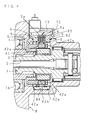
- FIG. 4 is a cross-sectional view of the torque detection device incorporated into the housing 8.
- FIG. 5 is an enlarged cross-sectional view taken along the line V-V in FIG. 3.
- FIG. 6 is a perspective view showing the constitution of the torque detection device.
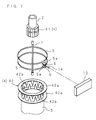
- FIG. 7 is a schematic exploded perspective view of the torque detection device.
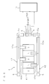
- FIG. 8 is a diagram for describing a magnetic circuit generated when a rotating body is rotated in one direction.
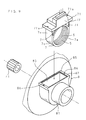
- FIG. 9 is a partial exploded perspective view of the torque detection device.
- An inventive torque detection device includes: two magnetic flux collecting rings 5, 5 for collecting a magnetic flux generated by a magnetic circuit forming member 4, which are located circumferentially of the magnetic circuit forming member 4 of first and second rotating bodies 2 and 3 coaxially connected via a torsion bar 1; a detection part 6 for detecting the torque applied to the first rotating body 2, based on the density of a magnetic flux collected by the magnetic flux collecting rings 5, 5; a holding ring 7 for holding the magnetic flux collecting rings 5, 5 and the detection part 6, which has a flange 71 attached to a housing 8 surrounding the magnetic circuit forming member 4; a sealing ring 9 for sealing between the flange 71 and the housing 8; and a magnetic shield plate 10 for covering the outer circumference of the holding ring 7.
- the magnetic circuit forming member 4 includes: a plurality of permanent magnets 41 attached to an outer circumferential part of the first rotating body 2; and two magnetic rings 42, 42 located circumferentially of the permanent magnets 41 and externally fitted to the second rotating body 3.
- the permanent magnets 41 are formed into a multi-pole magnetic ring in which a plurality of north and south poles are alternately arranged circumferentially, and the ring is externally fitted to the outer circumferential part of the first rotating body 2.
- the magnetic rings 42, 42 have: two opposing annular plates 42a, 42a separated form each other in the axial direction of the second rotating body 3; and a plurality of comb teeth 42b, 42b extended close to each other from inner circumferential parts of the annular plates 42a, 42a.
- the magnetic rings 42, 42 are formed so that the magnetic flux density between the magnetic rings 42, 42 is changed due to the relative rotation with the permanent magnets 41.
- the comb teeth 42b, 42b are arranged at equal intervals such that they intermesh alternately in the circumferential direction, and the magnetic rings 42, 42 are molded with a synthetic resin material in the state where the comb teeth 42b, 42b intermesh alternately, thus providing a molded body.
- the magnetic flux collecting rings 5, 5 form a cylindrical shape having convex pieces 5a, 5a extended radially outward from circumferential portions of the magnetic flux rings 5, 5 so as to be located on both sides of the detection part 6, thus allowing the convex pieces 5a, 5a to collect a magnetic flux.
- the magnetic flux collecting rings 5, 5 are a formed magnetic plate such as a steel plate, and are located so as to be axially separated from each other.
- the holding ring 7 holds the magnetic flux collecting rings 5, 5 by molding the magnetic flux collecting rings 5, 5 with a synthetic resin material.
- This holding ring 7 has a through hole 7a corresponding to inner circumferential faces of the magnetic flux collecting rings 5, 5, and the magnetic flux collecting rings 5, 5 are fitted to the through hole 7a.
- the holding ring 7 further has: axial both end faces 7b, 7b; an approximately semicircular outer circumferential face 7c; and two extended outer surfaces 7d, 7d extended tangentially from the outer circumferential face 7c.
- the circumferential face of the holding ring 7 between both the end faces 7b, 7b is approximately U-shaped, and the extended side of each of the extended outer surfaces 7d, 7d has a rectangular cross section.
- the flange 71 having a cuboid shape at the extended ends of the extended outer surfaces 7d, 7d, a rectangular cylindrical part 72 protruded at the center of the flange 71, and the holding ring 7 are integrally molded with a synthetic resin material.
- a plurality of concave portions 7f for equalizing the thickness of the holding ring 7 are provided.
- the holding ring 7 is further provided with a prevention wall 7e that is continuous with the flange 71 and brought into contact with an inner circumferential face of the sealing ring 9 so as to prevent the displacement of the sealing ring 9 into the concave portions 7f (see FIGS. 3 and 5).
- the concave portions 7f are each formed into an approximately triangular shape and are recessed axially from both the end faces 7b, 7b.
- the prevention wall 7e is formed to have a width substantially similar to the thickness of the sealing ring 9 along the inner circumferential face of the sealing ring 9, and is continuous with a base end of the flange 71 so that an opening of each concave portion 7f is partially closed.
- the flange 71 has a plate-like shape that forms a cuboid, and the flange 71 is provided, at its circumferentially distributed two portions, with insertion holes 71a, 71a through which small screws are to be inserted.
- a detection circuit board 13 connected to the detection part 6 is molded with a synthetic resin material, and a conductor 14 is connected to the detection circuit board 13.
- the detection part 6 includes a Hall element whose electrical characteristic (resistance) varies in accordance with a change in the magnetic flux density generated between the convex pieces 5a, 5a of the magnetic flux collecting rings 5, 5, and is configured so as to change a detection signal in accordance with a change in the magnetic flux density generated between the convex pieces 5a, 5a of the magnetic flux collecting rings 5, 5.
- a detection signal from the detection part 6 is sent to the detection circuit board 13.
- the detection part 6 may alternatively have a magnetic sensing element whose electrical characteristic (resistance) varies due to a magnetic field effect, such as a magnetoresistance effect element (MR element); therefore, a constituent element of the detection part 6 is not limited to a Hall element.
- MR element magnetoresistance effect element
- the magnetic shield plate 10 is approximately U-shaped in a manner corresponding to the shapes of the outer circumferential face 7c and the extended outer surfaces 7d, 7d, and is formed by a flexible nonmagnetic member such as a silicon steel plate. Further, at both ends of the magnetic shield plate 10, engaging pieces 10a, 10a that are engaged with the concave portions 7f by calking are protruded (see FIG. 3).
- the housing 8 as an appropriate object has: a cylindrical part 81 surrounding the magnetic circuit forming member 4; an attachment seat 82 which is protruded at a portion of an outer circumferential part of the cylindrical part 81, and to which the holding ring 7 is to be attached; a through hole 83 that radially passes through the attachment seat 82 and that forms a rectangular cross section for allowing the holding ring 7 to be located inside the cylindrical part 81; and a fitting groove 84 that is continuous with the through hole 83 and is bent in a manner corresponding to the shape of the holding ring 7 (see FIG. 4).
- the attachment seat 82 is formed into a rectangular annular shape in a manner corresponding to the shape of the flange 71, and an annular groove 85 for accommodating the sealing ring 9 is provided at an inner portion of the attachment seat 82. Furthermore, at an outer portion of the attachment seat 82, two screw holes 86, 86 corresponding to the insertion holes 71a, 71a are provided.
- the sealing ring 9 is externally fitted and held at the flange 71 side of the holding ring 7, and the holding ring 7 is inserted into the cylindrical part 81 through the through hole 83 that passes through the attachment seat 82 of the housing 8. Furthermore, by allowing the holding ring 7 to engage with the fitting groove 84, the position of the holding ring 7 inside the cylindrical part 81 is determined, and the sealing ring 9 is brought into contact with the annular groove 85 so that the sealing ring 9 is sandwiched and fixed between the flange 71 and the attachment seat 82.
- a component such as the rotating bodies 2, 3 provided with the magnet circuit forming member 4 and a sealed bearing 16 for rotatably supporting the rotating bodies 2, 3, is inserted into the housing 8 from the axial direction of the housing 8, thus providing the assembly in which the inside of the housing 8 is sealed. Therefore, during the assembly, the air pressure inside the housing 8 might be reduced. In such a case, due to this air pressure reduction, the air pressure inside the concave portions 7f, slightly communicated with the inside of the housing 8 via the through hole 83, might be also reduced.
- the holding ring 7 is provided with the prevention wall 7e that is brought into contact with the inner circumferential face of the sealing ring 9 to prevent the displacement of the sealing ring 9 into the concave portions 7f, and the inner circumferential face of the sealing ring 9 is brought into contact with the prevention wall 7e. Therefore, the adverse influence of the thinned concave portions 7f is eliminated, thus making it possible to prevent the displacement and fall of the sealing ring 9 into the concave portions 7f.
- the torque detection device constructed as described above may be used as an electrical power steering device for a vehicle, for example.
- the device is disposed in an area exposed to water splashed from outside the vehicle or water for washing the vehicle; therefore, when the temperature inside the housing 8 is sharply reduced due to the splashed water or water for washing the vehicle, the air pressure inside the concave portions 7f, slightly communicated with the inside of the housing 8 via the through hole 83, is also reduced.
- the holding ring 7 is provided, at its portions facing the concave portions 7f, with the prevention wall 7e, and the inner circumferential face of the sealing ring 9 is brought into contact with the prevention wall 7e, the adverse influence of the thinned concave portions 7f is eliminated, thus making it possible to prevent the displacement and fall of the sealing ring 9 into the concave portions 7f.
- the flange 71 is reinforced with the prevention wall 7e. Accordingly, the flange 71, molded integrally with the holding ring 7 using a synthetic resin material, can be prevented from being deformed in the thickness direction, the surface of the flange 71 in contact with the sealing ring 9 can be kept flat, the sandwiching force applied to the sealing ring 9 can be equalized, and the sealing property of the sealing ring 9 can be improved.
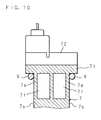
- FIG. 10 is an enlarged cross-sectional view of the principal part of the torque detection device, showing another constitution thereof.
- the concave portions 7f are recessed axially from both the end faces 7b, 7b of the holding ring 7 according to the above-described embodiment, the concave portions 7f may alternatively be formed such that openings located close to both the end faces 7b, 7b are closed and sealed, for example.
Landscapes
- Physics & Mathematics (AREA)
- General Physics & Mathematics (AREA)
- Electromagnetism (AREA)
- Power Steering Mechanism (AREA)
Abstract
Description
- The present invention relates to a torque detection device for detecting the torque applied to a rotating body.
- An exemplary torque detection device is disclosed in
Japanese Patent Application Laid-Open No. 2005-300267 Japanese Patent Application Laid-Open No. 2005-300267 - In addition, the holding ring further has: axial both end faces; an approximately semicircular outer circumferential face; and two extended outer surfaces extended tangentially from the outer circumferential face. And the flange is continuous with each of the extended outer surfaces and both the end faces.
- However, the torque detection device formed as described in
Japanese Patent Application Laid-Open No. 2005-300267 - FIG. 1 is a front view showing the constitution of an improved torque detection device. FIG. 2 is an enlarged cross-sectional view taken along the line II-II in FIG. 1. As shown in FIGS. 1 and 2, the applicant of the present invention has developed a torque detection device in which both end faces 102, 102 between two extended
outer surfaces holding ring 100 are provided with thinnedconcave portions outer surfaces through hole 104 of theholding ring 100, and between aflange 103 and thethrough hole 104 of theholding ring 100. - The torque detection device formed in this manner can suppress the sink mark of the
holding ring 100 without shortening the distance between the two extendedouter surfaces holding ring 100. However, although a sealingring 106 is located around the thinnedconcave portions 105, a portion of the sealingring 106 facing the thinnedconcave portions 105 is not brought into contact with the holding ring 100 (see FIG. 2). Therefore, after the torque detection device has been incorporated into ahousing 107, the air pressure within thehousing 107 might be decreased when a rotating body is built into thehousing 107. Or in the state where the torque detection device and the rotating body are built into thehousing 107, upon decrease of the air pressure within thehousing 107 due to the conditions outside of thehousing 107, there occurs a reduction in the pressure inside the thinnedconcave portions 105 communicated with the inside of thehousing 107 via a through hole into which theholding ring 100 is inserted. In such a case, a portion of the sealingring 106 facing the thinnedconcave portions 105 might be sucked into the thinnedconcave portions 105 and fall into the thinnedconcave portions 105. Furthermore, since both the end faces 102, 102 and theflange 103 of theholding ring 100 are not continuous at the thinnedconcave portions 105, theflange 103 is likely to undulately deform in the thickness direction due to the temperature change outside of thehousing 107, which might partially degrade the sandwiching of thesealing ring 106 by theflange 103 to decrease the sealing property of thesealing ring 106. - The present invention has been made in view of the above-described problems, and its main object is to provide a torque detection device that can prevent the fall of a sealing ring into a thinned concave portion and the deformation of a flange, although the thickness of a holding ring can be equalized by the thinned concave portion.
- A torque detection device according to a first aspect of the present invention includes: a magnetic flux collecting ring for collecting a magnetic flux generated by a magnetic circuit forming member provided at a rotating body to which a torque is applied, the magnetic flux collecting ring being located circumferentially of the magnetic circuit forming member; a detection part for detecting, based on a density of the magnetic flux collected by the magnetic flux collecting ring, the torque applied to the rotating body; a holding ring for holding the magnetic flux collecting ring and the detection part, the holding ring having a flange to be attached to an appropriate object; and a sealing ring for sealing between the flange and the object, the device characterized in that the holding ring has: a concave portion formed at a region thereof close to the flange; and a prevention wall that is continuous with the flange and brought into contact with an inner circumferential face of the sealing ring so as to prevent the displacement of the sealing ring into the concave portion.
- In the torque detection device according to the first aspect of the present invention, the thickness of the holding ring can be equalized by the existence of the concave portion. Moreover, since the holding ring has the prevention wall that is continuous with the flange and brought into contact with the inner circumferential face of the sealing ring so as to prevent the displacement of the sealing ring into the concave portion, it is possible to prevent the fall of the sealing ring into the concave portion when the air pressure is reduced, and to prevent the deformation of the flange.
- The torque detection device according to a second aspect of the present invention is characterized in that the holding ring further has: axial both end faces; an approximately semicircular outer circumferential face; and two extended outer surfaces extended tangentially from the outer circumferential face, and the concave portion is provided at both the end faces.
- In the torque detection device according to the second aspect of the present invention, it is possible to suppress the sink mark of the holding ring without shortening the distance between the two extended outer surfaces of the holding ring, and to improve the rigidity of the holding ring.
- The above and further objects and features of the invention will more fully be apparent from the following detailed description with accompanying drawings.
-
- FIG. 1 is a front view showing the constitution of an improved torque detection device;
- FIG. 2 is an enlarged cross-sectional view taken along the line II-II in FIG. 1;
- FIG. 3 is a front view of a torque detection device according to the present invention, incorporated into a housing;
- FIG. 4 is a cross-sectional view of the torque detection device according to the present invention, incorporated into the housing;
- FIG. 5 is an enlarged cross-sectional view taken along the line V-V in FIG. 3;
- FIG. 6 is a perspective view showing the constitution of the torque detection device according to the present invention;
- FIG. 7 is a schematic exploded perspective view of the torque detection device according to the present invention;
- FIG. 8 is a diagram for describing a magnetic circuit generated when a rotating body is rotated in one direction;
- FIG. 9 is a partial exploded perspective view of the torque detection device according to the present invention; and
- FIG. 10 is an enlarged cross-sectional view of the principal part of the torque detection device according to the present invention, showing another constitution thereof.
- Hereinafter, embodiments of the present invention will be described in detail with reference to the drawings. FIG. 3 is a front view of a torque detection device according to the present invention, incorporated into a housing. FIG. 4 is a cross-sectional view of the torque detection device incorporated into the
housing 8. FIG. 5 is an enlarged cross-sectional view taken along the line V-V in FIG. 3. FIG. 6 is a perspective view showing the constitution of the torque detection device. FIG. 7 is a schematic exploded perspective view of the torque detection device. FIG. 8 is a diagram for describing a magnetic circuit generated when a rotating body is rotated in one direction. And FIG. 9 is a partial exploded perspective view of the torque detection device. - An inventive torque detection device includes: two magnetic
flux collecting rings circuit forming member 4, which are located circumferentially of the magneticcircuit forming member 4 of first and secondrotating bodies torsion bar 1; adetection part 6 for detecting the torque applied to the first rotatingbody 2, based on the density of a magnetic flux collected by the magneticflux collecting rings holding ring 7 for holding the magneticflux collecting rings detection part 6, which has aflange 71 attached to ahousing 8 surrounding the magneticcircuit forming member 4; asealing ring 9 for sealing between theflange 71 and thehousing 8; and amagnetic shield plate 10 for covering the outer circumference of theholding ring 7. It should be noted that the magneticcircuit forming member 4 includes: a plurality ofpermanent magnets 41 attached to an outer circumferential part of the first rotatingbody 2; and twomagnetic rings permanent magnets 41 and externally fitted to the second rotatingbody 3. - The
permanent magnets 41 are formed into a multi-pole magnetic ring in which a plurality of north and south poles are alternately arranged circumferentially, and the ring is externally fitted to the outer circumferential part of the first rotatingbody 2. - The
magnetic rings body 3; and a plurality ofcomb teeth magnetic rings magnetic rings permanent magnets 41. Thecomb teeth magnetic rings comb teeth - The magnetic flux collecting
rings pieces magnetic flux rings detection part 6, thus allowing theconvex pieces rings - The
holding ring 7 holds the magneticflux collecting rings flux collecting rings holding ring 7 has a through hole 7a corresponding to inner circumferential faces of the magnetic flux collectingrings rings holding ring 7 further has: axial bothend faces circumferential face 7c; and two extended outer surfaces 7d, 7d extended tangentially from the outercircumferential face 7c. The circumferential face of theholding ring 7 between both the end faces 7b, 7b is approximately U-shaped, and the extended side of each of the extended outer surfaces 7d, 7d has a rectangular cross section. Theflange 71 having a cuboid shape at the extended ends of the extended outer surfaces 7d, 7d, a rectangularcylindrical part 72 protruded at the center of theflange 71, and theholding ring 7 are integrally molded with a synthetic resin material. - At the
flange 71 side of both the end faces 7b, 7b, a plurality of concave portions 7f for equalizing the thickness of theholding ring 7 are provided. In addition, theholding ring 7 is further provided with aprevention wall 7e that is continuous with theflange 71 and brought into contact with an inner circumferential face of thesealing ring 9 so as to prevent the displacement of thesealing ring 9 into the concave portions 7f (see FIGS. 3 and 5). The concave portions 7f are each formed into an approximately triangular shape and are recessed axially from both theend faces prevention wall 7e is formed to have a width substantially similar to the thickness of thesealing ring 9 along the inner circumferential face of thesealing ring 9, and is continuous with a base end of theflange 71 so that an opening of each concave portion 7f is partially closed. - The
flange 71 has a plate-like shape that forms a cuboid, and theflange 71 is provided, at its circumferentially distributed two portions, withinsertion holes cylindrical part 72, adetection circuit board 13 connected to thedetection part 6 is molded with a synthetic resin material, and aconductor 14 is connected to thedetection circuit board 13. - The
detection part 6 includes a Hall element whose electrical characteristic (resistance) varies in accordance with a change in the magnetic flux density generated between theconvex pieces convex pieces detection part 6 is sent to thedetection circuit board 13. It should be noted that other than a Hall element, thedetection part 6 may alternatively have a magnetic sensing element whose electrical characteristic (resistance) varies due to a magnetic field effect, such as a magnetoresistance effect element (MR element); therefore, a constituent element of thedetection part 6 is not limited to a Hall element. - The
magnetic shield plate 10 is approximately U-shaped in a manner corresponding to the shapes of the outercircumferential face 7c and the extended outer surfaces 7d, 7d, and is formed by a flexible nonmagnetic member such as a silicon steel plate. Further, at both ends of themagnetic shield plate 10, engaging pieces 10a, 10a that are engaged with the concave portions 7f by calking are protruded (see FIG. 3). - The
housing 8 as an appropriate object has: acylindrical part 81 surrounding the magneticcircuit forming member 4; anattachment seat 82 which is protruded at a portion of an outer circumferential part of thecylindrical part 81, and to which the holdingring 7 is to be attached; a throughhole 83 that radially passes through theattachment seat 82 and that forms a rectangular cross section for allowing the holdingring 7 to be located inside thecylindrical part 81; and afitting groove 84 that is continuous with the throughhole 83 and is bent in a manner corresponding to the shape of the holding ring 7 (see FIG. 4). - The
attachment seat 82 is formed into a rectangular annular shape in a manner corresponding to the shape of theflange 71, and anannular groove 85 for accommodating thesealing ring 9 is provided at an inner portion of theattachment seat 82. Furthermore, at an outer portion of theattachment seat 82, twoscrew holes insertion holes - In the torque detection device constructed as described above, the sealing
ring 9 is externally fitted and held at theflange 71 side of the holdingring 7, and the holdingring 7 is inserted into thecylindrical part 81 through the throughhole 83 that passes through theattachment seat 82 of thehousing 8. Furthermore, by allowing the holdingring 7 to engage with thefitting groove 84, the position of the holdingring 7 inside thecylindrical part 81 is determined, and thesealing ring 9 is brought into contact with theannular groove 85 so that the sealingring 9 is sandwiched and fixed between theflange 71 and theattachment seat 82. After theholding ring 7 has been inserted into thehousing 8 in this manner,small screws insertion holes flange 71, thus attaching the holdingring 7 to the attachment seat 82 (see FIGS. 3 and 4). - After the torque detection device has been attached to the
housing 8 as described above, a component, such as therotating bodies circuit forming member 4 and a sealedbearing 16 for rotatably supporting therotating bodies housing 8 from the axial direction of thehousing 8, thus providing the assembly in which the inside of thehousing 8 is sealed. Therefore, during the assembly, the air pressure inside thehousing 8 might be reduced. In such a case, due to this air pressure reduction, the air pressure inside the concave portions 7f, slightly communicated with the inside of thehousing 8 via the throughhole 83, might be also reduced. However, the holdingring 7 is provided with theprevention wall 7e that is brought into contact with the inner circumferential face of the sealingring 9 to prevent the displacement of the sealingring 9 into the concave portions 7f, and the inner circumferential face of the sealingring 9 is brought into contact with theprevention wall 7e. Therefore, the adverse influence of the thinned concave portions 7f is eliminated, thus making it possible to prevent the displacement and fall of the sealingring 9 into the concave portions 7f. - Moreover, the torque detection device constructed as described above may be used as an electrical power steering device for a vehicle, for example. In that case, the device is disposed in an area exposed to water splashed from outside the vehicle or water for washing the vehicle; therefore, when the temperature inside the
housing 8 is sharply reduced due to the splashed water or water for washing the vehicle, the air pressure inside the concave portions 7f, slightly communicated with the inside of thehousing 8 via the throughhole 83, is also reduced. However, since the holdingring 7 is provided, at its portions facing the concave portions 7f, with theprevention wall 7e, and the inner circumferential face of the sealingring 9 is brought into contact with theprevention wall 7e, the adverse influence of the thinned concave portions 7f is eliminated, thus making it possible to prevent the displacement and fall of the sealingring 9 into the concave portions 7f. - Furthermore, since the
prevention wall 7e is continuous with theflange 71 for the attachment of the holdingring 7 to thehousing 8, theflange 71 is reinforced with theprevention wall 7e. Accordingly, theflange 71, molded integrally with the holdingring 7 using a synthetic resin material, can be prevented from being deformed in the thickness direction, the surface of theflange 71 in contact with the sealingring 9 can be kept flat, the sandwiching force applied to thesealing ring 9 can be equalized, and the sealing property of the sealingring 9 can be improved. - FIG. 10 is an enlarged cross-sectional view of the principal part of the torque detection device, showing another constitution thereof. Although the concave portions 7f are recessed axially from both the end faces 7b, 7b of the holding
ring 7 according to the above-described embodiment, the concave portions 7f may alternatively be formed such that openings located close to both the end faces 7b, 7b are closed and sealed, for example.
Claims (7)
- A torque detection device comprising: a magnetic flux collecting ring (5) for collecting a magnetic flux generated by a magnetic circuit forming member (4) provided at a rotating body (2) to which a torque is applied, the magnetic flux collecting ring (5) being located circumferentially of the magnetic circuit forming member (4); a detection part (6) for detecting, based on a density of the magnetic flux collected by the magnetic flux collecting ring (5), the torque applied to the rotating body (2); a holding ring (7) for holding the magnetic flux collecting ring (5) and the detection part (6), the holding ring (7) having a flange (71) to be attached to an appropriate object (8); and a sealing ring (9) for sealing between the flange (71) and the object (8), the torque detection device characterized in that the holding ring (7) has: a concave portion (7f) formed at a region thereof close to the flange (71); and a prevention wall (7e) that is continuous with the flange (71) and brought into contact with an inner circumferential face of the sealing ring (9) so as to prevent the displacement of the sealing ring (9) into the concave portion (7f).
- The torque detection device according to Claim 1,
wherein the holding ring (7) further has : axial both end faces (7b); an approximately semicircular outer circumferential face (7c); and two extended outer surfaces (7d) extended tangentially from the outer circumferential face (7c), and the concave portion (7f) is provided at both the end faces (7b). - The torque detection device according to Claim 2,
wherein the concave portion (7f) is formed into an approximately triangular shape, and is recessed axially from both the end faces (7b). - The torque detection device according to any one of Claims 1 to 3,
wherein the prevention wall (7e) is formed to have a width substantially similar to a thickness of the sealing ring (9) along the inner circumferential face of the sealing ring (9). - The torque detection device according to any one of Claims 1 to 4,
wherein an opening of the concave portion (7f) is partially closed by the prevention wall (7e). - The torque detection device according to Claim 2,
wherein an opening of the concave portion (7f) located close to both the end faces (7b) is closed by the prevention wall (7e). - The torque detection device according to any one of Claims 1 to 6,
wherein the holding ring (7) holds the magnetic flux collecting ring (5) and the detection part (6) by molding the magnetic flux collecting ring (5) and the detection part (6) with a synthetic resin material.
Applications Claiming Priority (1)
| Application Number | Priority Date | Filing Date | Title |
|---|---|---|---|
| JP2006005277A JP2007187527A (en) | 2006-01-12 | 2006-01-12 | Torque detection device |
Publications (3)
| Publication Number | Publication Date |
|---|---|
| EP1808681A2 true EP1808681A2 (en) | 2007-07-18 |
| EP1808681A3 EP1808681A3 (en) | 2010-01-13 |
| EP1808681B1 EP1808681B1 (en) | 2019-10-23 |
Family
ID=37944948
Family Applications (1)
| Application Number | Title | Priority Date | Filing Date |
|---|---|---|---|
| EP07100163.0A Ceased EP1808681B1 (en) | 2006-01-12 | 2007-01-05 | Magnetic torque detection device |
Country Status (3)
| Country | Link |
|---|---|
| US (1) | US7428847B2 (en) |
| EP (1) | EP1808681B1 (en) |
| JP (1) | JP2007187527A (en) |
Cited By (1)
| Publication number | Priority date | Publication date | Assignee | Title |
|---|---|---|---|---|
| EP2020590A3 (en) * | 2007-07-23 | 2012-12-26 | GM Global Technology Operations LLC | Apparatus for sensing position and/or torque |
Families Citing this family (7)
| Publication number | Priority date | Publication date | Assignee | Title |
|---|---|---|---|---|
| JP4877715B2 (en) * | 2005-09-28 | 2012-02-15 | 株式会社ジェイテクト | Torque detection device and electric power steering device using the same |
| JP4794262B2 (en) * | 2005-09-30 | 2011-10-19 | 株式会社ジェイテクト | Torque detection device and electric power steering device using the same |
| WO2008068339A1 (en) * | 2006-12-07 | 2008-06-12 | Continental Teves Ag & Co. Ohg | Torque sensor arrangement |
| JP5191774B2 (en) * | 2008-03-31 | 2013-05-08 | カヤバ工業株式会社 | Torque sensor and manufacturing method thereof |
| JP5153490B2 (en) * | 2008-07-11 | 2013-02-27 | カヤバ工業株式会社 | Torque sensor |
| DE102008044059A1 (en) * | 2008-11-25 | 2010-05-27 | Zf Lenksysteme Gmbh | Sensor device for torque measurement in steering systems |
| JP6056458B2 (en) * | 2012-12-25 | 2017-01-11 | 株式会社ジェイテクト | Torque detection device and steering device including the same |
Family Cites Families (20)
| Publication number | Priority date | Publication date | Assignee | Title |
|---|---|---|---|---|
| US4899597A (en) * | 1987-02-27 | 1990-02-13 | Honda Giken Kogyo Kabushiki Kaisha | Torque sensor |
| JPS63210739A (en) * | 1987-02-27 | 1988-09-01 | Honda Motor Co Ltd | Torque sensor |
| JPH11248564A (en) * | 1998-02-26 | 1999-09-17 | Nippon Seiko Kk | Torque sensor |
| JP3346268B2 (en) * | 1998-02-26 | 2002-11-18 | 日本精工株式会社 | Torque sensor |
| JP3674941B2 (en) * | 1999-10-06 | 2005-07-27 | 日本精工株式会社 | Torque sensor unit for electric power steering system |
| FR2824910B1 (en) * | 2001-05-18 | 2005-05-13 | Denso Corp | TORQUE SENSOR AND POWER ASSISTED STEERING SYSTEM EMPLOYING THIS SENSOR |
| JP3593102B2 (en) * | 2002-01-08 | 2004-11-24 | 三菱電機株式会社 | Electric power steering device |
| JP2003240652A (en) * | 2002-02-15 | 2003-08-27 | Denso Corp | Semiconductor sensor with built-in output correction circuit and torsion bar type torque sensor |
| JP3913657B2 (en) * | 2002-10-02 | 2007-05-09 | 株式会社日本自動車部品総合研究所 | Torque sensor |
| JP4190849B2 (en) * | 2002-10-07 | 2008-12-03 | 株式会社日本自動車部品総合研究所 | Torque sensor |
| JP2004159380A (en) * | 2002-11-01 | 2004-06-03 | Sumitomo Wiring Syst Ltd | Mounting structure of electrical junction box |
| FR2847341B1 (en) * | 2002-11-14 | 2005-11-04 | Denso Corp | MAGNETIC RING TORQUE SENSOR |
| JP5146711B2 (en) * | 2003-05-29 | 2013-02-20 | アイシン精機株式会社 | Resin-sealed product manufacturing method and case |
| JP2005265581A (en) * | 2004-03-18 | 2005-09-29 | Favess Co Ltd | Torque detection device |
| JP4656851B2 (en) | 2004-03-18 | 2011-03-23 | 株式会社ジェイテクト | Torque detection device |
| JP4753545B2 (en) * | 2004-04-08 | 2011-08-24 | 株式会社ジェイテクト | Torque detection device and manufacturing method thereof |
| EP2233901A1 (en) | 2004-04-08 | 2010-09-29 | Jtekt Corporation | Torque detecting apparatus and manufacturing method thereof |
| JP4161937B2 (en) * | 2004-05-12 | 2008-10-08 | トヨタ自動車株式会社 | Vane type variable valve timing mechanism seal structure |
| EP1621447B1 (en) * | 2004-07-29 | 2013-09-25 | Jtekt Corporation | Torque detecting apparatus and electric power steering apparatus |
| JP4812303B2 (en) * | 2005-01-20 | 2011-11-09 | 株式会社ジェイテクト | Torque detection device |
-
2006
- 2006-01-12 JP JP2006005277A patent/JP2007187527A/en active Pending
-
2007
- 2007-01-05 EP EP07100163.0A patent/EP1808681B1/en not_active Ceased
- 2007-01-11 US US11/652,033 patent/US7428847B2/en active Active
Cited By (1)
| Publication number | Priority date | Publication date | Assignee | Title |
|---|---|---|---|---|
| EP2020590A3 (en) * | 2007-07-23 | 2012-12-26 | GM Global Technology Operations LLC | Apparatus for sensing position and/or torque |
Also Published As
| Publication number | Publication date |
|---|---|
| US7428847B2 (en) | 2008-09-30 |
| US20070169569A1 (en) | 2007-07-26 |
| EP1808681B1 (en) | 2019-10-23 |
| JP2007187527A (en) | 2007-07-26 |
| EP1808681A3 (en) | 2010-01-13 |
Similar Documents
| Publication | Publication Date | Title |
|---|---|---|
| US7428847B2 (en) | Torque detection device | |
| JP6217608B2 (en) | Magnetic detection device and torque sensor using the same | |
| US7509883B2 (en) | Torque detecting apparatus and manufacturing method thereof | |
| EP2833110B1 (en) | Torque detecting device and electric power steering system | |
| JP5401902B2 (en) | motor | |
| CN101017115B (en) | Torque detection device and manufacturing method thereof | |
| US11353521B2 (en) | Magnetic detection module, detection device, case assembly, and production method for magnetic detection module | |
| JP5064315B2 (en) | Rotation angle sensor | |
| EP2626987B1 (en) | Sensing magnet apparatus for motor | |
| EP1813925B1 (en) | Torque Detection Device | |
| EP3618230A1 (en) | Sensing device | |
| JP2010078586A (en) | Assembly structure of electric current detection device | |
| US11579211B2 (en) | Detection device | |
| EP3190029A1 (en) | Torque sensor device | |
| JP6726593B2 (en) | Torque sensor | |
| WO2011027482A1 (en) | Rotation detecting apparatus | |
| EP1947435B1 (en) | Torque detector and electric power steering device using the same | |
| JP2007187589A (en) | Torque detection device | |
| JP2005321361A (en) | Torque detection device | |
| JP2007187481A (en) | Torque detection device | |
| EP3312564A1 (en) | Rotational angle detecting device and angle sensor unit used therein | |
| JP2018059741A (en) | Torque sensor manufacturing method | |
| JP2007127483A (en) | Torque detection device | |
| JP2007187627A (en) | Torque detection device | |
| JP2018059740A (en) | Torque sensor |
Legal Events
| Date | Code | Title | Description |
|---|---|---|---|
| PUAI | Public reference made under article 153(3) epc to a published international application that has entered the european phase |
Free format text: ORIGINAL CODE: 0009012 |
|
| AK | Designated contracting states |
Kind code of ref document: A2 Designated state(s): AT BE BG CH CY CZ DE DK EE ES FI FR GB GR HU IE IS IT LI LT LU LV MC NL PL PT RO SE SI SK TR |
|
| AX | Request for extension of the european patent |
Extension state: AL BA HR MK YU |
|
| PUAL | Search report despatched |
Free format text: ORIGINAL CODE: 0009013 |
|
| AK | Designated contracting states |
Kind code of ref document: A3 Designated state(s): AT BE BG CH CY CZ DE DK EE ES FI FR GB GR HU IE IS IT LI LT LU LV MC NL PL PT RO SE SI SK TR |
|
| AX | Request for extension of the european patent |
Extension state: AL BA HR MK RS |
|
| 17P | Request for examination filed |
Effective date: 20100708 |
|
| AKX | Designation fees paid |
Designated state(s): DE FR |
|
| 17Q | First examination report despatched |
Effective date: 20121105 |
|
| STAA | Information on the status of an ep patent application or granted ep patent |
Free format text: STATUS: EXAMINATION IS IN PROGRESS |
|
| REG | Reference to a national code |
Ref country code: DE Ref legal event code: R079 Ref document number: 602007059387 Country of ref document: DE Free format text: PREVIOUS MAIN CLASS: G01L0003100000 Ipc: G01L0005220000 |
|
| GRAP | Despatch of communication of intention to grant a patent |
Free format text: ORIGINAL CODE: EPIDOSNIGR1 |
|
| STAA | Information on the status of an ep patent application or granted ep patent |
Free format text: STATUS: GRANT OF PATENT IS INTENDED |
|
| RIC1 | Information provided on ipc code assigned before grant |
Ipc: G01L 3/10 20060101ALI20190329BHEP Ipc: G01L 5/22 20060101AFI20190329BHEP |
|
| INTG | Intention to grant announced |
Effective date: 20190506 |
|
| GRAS | Grant fee paid |
Free format text: ORIGINAL CODE: EPIDOSNIGR3 |
|
| GRAA | (expected) grant |
Free format text: ORIGINAL CODE: 0009210 |
|
| STAA | Information on the status of an ep patent application or granted ep patent |
Free format text: STATUS: THE PATENT HAS BEEN GRANTED |
|
| AK | Designated contracting states |
Kind code of ref document: B1 Designated state(s): DE FR |
|
| RAP1 | Party data changed (applicant data changed or rights of an application transferred) |
Owner name: DENSO CORPORATION Owner name: JTEKT CORPORATION |
|
| RIN1 | Information on inventor provided before grant (corrected) |
Inventor name: OSUKA, AKIO Inventor name: ISHIHARA, TOSHIHARU Inventor name: NAKANE, NAOKI |
|
| REG | Reference to a national code |
Ref country code: DE Ref legal event code: R096 Ref document number: 602007059387 Country of ref document: DE |
|
| REG | Reference to a national code |
Ref country code: DE Ref legal event code: R097 Ref document number: 602007059387 Country of ref document: DE |
|
| PLBE | No opposition filed within time limit |
Free format text: ORIGINAL CODE: 0009261 |
|
| STAA | Information on the status of an ep patent application or granted ep patent |
Free format text: STATUS: NO OPPOSITION FILED WITHIN TIME LIMIT |
|
| 26N | No opposition filed |
Effective date: 20200724 |
|
| PGFP | Annual fee paid to national office [announced via postgrant information from national office to epo] |
Ref country code: FR Payment date: 20221208 Year of fee payment: 17 |
|
| PGFP | Annual fee paid to national office [announced via postgrant information from national office to epo] |
Ref country code: DE Payment date: 20221130 Year of fee payment: 17 |
|
| REG | Reference to a national code |
Ref country code: DE Ref legal event code: R119 Ref document number: 602007059387 Country of ref document: DE |
|
| PG25 | Lapsed in a contracting state [announced via postgrant information from national office to epo] |
Ref country code: DE Free format text: LAPSE BECAUSE OF NON-PAYMENT OF DUE FEES Effective date: 20240801 |
|
| PG25 | Lapsed in a contracting state [announced via postgrant information from national office to epo] |
Ref country code: FR Free format text: LAPSE BECAUSE OF NON-PAYMENT OF DUE FEES Effective date: 20240131 |
|
| PG25 | Lapsed in a contracting state [announced via postgrant information from national office to epo] |
Ref country code: FR Free format text: LAPSE BECAUSE OF NON-PAYMENT OF DUE FEES Effective date: 20240131 Ref country code: DE Free format text: LAPSE BECAUSE OF NON-PAYMENT OF DUE FEES Effective date: 20240801 |