EP1808663A1 - Method of configuring weapon - Google Patents
Method of configuring weapon Download PDFInfo
- Publication number
- EP1808663A1 EP1808663A1 EP06100439A EP06100439A EP1808663A1 EP 1808663 A1 EP1808663 A1 EP 1808663A1 EP 06100439 A EP06100439 A EP 06100439A EP 06100439 A EP06100439 A EP 06100439A EP 1808663 A1 EP1808663 A1 EP 1808663A1
- Authority
- EP
- European Patent Office
- Prior art keywords
- barrel
- weapon
- compartment
- transport box
- countermass
- Prior art date
- Legal status (The legal status is an assumption and is not a legal conclusion. Google has not performed a legal analysis and makes no representation as to the accuracy of the status listed.)
- Granted
Links
- 238000000034 method Methods 0.000 title claims abstract description 18
- 230000000452 restraining effect Effects 0.000 claims abstract description 6
- 239000003380 propellant Substances 0.000 description 7
- 230000000295 complement effect Effects 0.000 description 2
- 238000005474 detonation Methods 0.000 description 2
- 238000010304 firing Methods 0.000 description 2
- 238000009434 installation Methods 0.000 description 2
- RTAQQCXQSZGOHL-UHFFFAOYSA-N Titanium Chemical compound [Ti] RTAQQCXQSZGOHL-UHFFFAOYSA-N 0.000 description 1
- 230000003213 activating effect Effects 0.000 description 1
- 238000011161 development Methods 0.000 description 1
- 230000018109 developmental process Effects 0.000 description 1
- 238000006073 displacement reaction Methods 0.000 description 1
- 239000003733 fiber-reinforced composite Substances 0.000 description 1
- 239000000463 material Substances 0.000 description 1
- 239000000203 mixture Substances 0.000 description 1
- 238000007789 sealing Methods 0.000 description 1
- 229910052719 titanium Inorganic materials 0.000 description 1
- 239000010936 titanium Substances 0.000 description 1
- 238000004804 winding Methods 0.000 description 1
Images
Classifications
-
- F—MECHANICAL ENGINEERING; LIGHTING; HEATING; WEAPONS; BLASTING
- F41—WEAPONS
- F41A—FUNCTIONAL FEATURES OR DETAILS COMMON TO BOTH SMALLARMS AND ORDNANCE, e.g. CANNONS; MOUNTINGS FOR SMALLARMS OR ORDNANCE
- F41A1/00—Missile propulsion characterised by the use of explosive or combustible propellant charges
- F41A1/08—Recoilless guns, i.e. guns having propulsion means producing no recoil
- F41A1/10—Recoilless guns, i.e. guns having propulsion means producing no recoil a counter projectile being used to balance recoil
-
- F—MECHANICAL ENGINEERING; LIGHTING; HEATING; WEAPONS; BLASTING
- F41—WEAPONS
- F41F—APPARATUS FOR LAUNCHING PROJECTILES OR MISSILES FROM BARRELS, e.g. CANNONS; LAUNCHERS FOR ROCKETS OR TORPEDOES; HARPOON GUNS
- F41F3/00—Rocket or torpedo launchers
- F41F3/04—Rocket or torpedo launchers for rockets
- F41F3/042—Rocket or torpedo launchers for rockets the launching apparatus being used also as a transport container for the rocket
Definitions
- the present invention relates to a method of configuring a weapon comprising a countermass in transport mode for restraining a shell in a barrel of said weapon. More particularly, the invention relates to a shell restraining method which is mainly adapted for transport and storing of a preloaded anti-armour weapon of the disposable type being stored in compartment of a transport box, in order to prevent the shell from exiting the barrel and detonating should the propellant charge of the shell accidentally ignite.
- One object of the present invention is to provide a shell restraining method for preventing a shell from exiting the barrel of the weapon should the propellant charge of the shell be accidentally ignited during transportation and storage of the weapon in a compartment box, and thereby preventing an accidental detonation of the shell in the vicinity.
- Another variant of the method according to the invention is characterized by the step of: e) placing said barrel in a first compartment and said countermass container in a second compartment of said transport box.
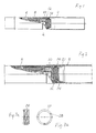
- Fig. 1 is a partial length-sectional view of the barrel of a preloaded anti-armour weapon of the disposable type
- fig. 2 is a more detailed disclosure in enlarged scale of fig. 1 including a locking ring mounted in the barrel
- figs. 3a and 3b show said locking ring in more detail
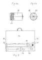
- figs. 4a and 4b show different views of an appropriate countermass container
- fig. 5 shows a transport box suitable for transport and storing of said weapon.
- Fig. 1 illustrates a partial length-sectional view through a preloaded anti-armour weapon 2 of the disposable type configured in transport mode.
- Said weapon includes a barrel 4 of fiber-reinforced composite material, which might be loaded, for example, with a round comprising a shell 6 including a fin assembly 8 and a propellant and igniter composition 10 housed in a cartridge case 12.
- a discharge nozzle 14 is mounted in said cartridge case by means of an annular sealing and said cartridge case in turn bear on a collar 16 in said barrel.
- a countermass container 18 of a previously known kind, which will be described in more detail later, would be mounted in the barrel 4 by means of a first locking means 20, e.g. a bayonet fitting or a self-locking screw thread, and thereby would bear on a protruding part of said nozzle.
- a first locking means 20 e.g. a bayonet fitting or a self-locking screw thread
- the method according to the present invention prescribes that the weapon 2 be configured in transport mode for restraining said shell 6 in the barrel 4, in order to prevent the shell from exiting the barrel and detonating should the propellant charge of the shell accidentally ignite.
- This is achieved, in transport mode, in that said counter mass container would not be mounted in the barrel 4, which would result in the cartridge case 12 and nozzle 14 being prevented from displacement axially in the barrel 4 in a launch direction, but allowed to be displaced in a counter-launch direction.
- the weapon is configured in transport mode by introduction of a locking ring 22, which is placed in the barrel 4 and mounted by means of a similar second locking means 24, for example a bayonet fitting or self-locking screw thread as previously described in connection with the countermass container, and thereby likewise would bear on the protruding part of the nozzle 14.
- said second locking means is configured as a self-locking screw thread 24.
- a suitable assembly tool 26 is introduced, which is configured as a bar with a trident in each end, a first trident and a second trident of a double grip assembly tool 26.
- the locking ring 22 on its inner surface, is provided with notches 28 configuring an internal tool grip complementary to said first trident of assembly tool 26.
- any suitable tool which can grip with said notches 28 in the locking ring might be used.
- Said second trident of assembly tool 26 will be used for reconfiguring the weapon in user mode as will be described later.
- the cartridge case and discharge nozzle would be prevented from axial movements in a launch direction and a counter-launch direction as well.
- the countermass container 18 is located outside the barrel 4, for example in compartment of a transport box 30, which will be described in more detail later.
- the present invention makes it possible to prevent the shell from exiting the barrel and detonating should the propellant charge of the shell accidentally ignite.
- this is achieved by placing the weapon comprising loaded barrel 4 including the shell 6 and cartridge case assembly 10, 12 with a discharge nozzle 14, in a first compartment 32 of said transport box and the countermass container 18 outside said loaded barrel, in a second compartment 34 of said transport box.
- the transport box might contain compartments for several weapons and countermass containers, preferably four of each.
- the separated first 32 and second 34 compartments are such arranged, that each weapon and countermass container is snugly lodged between end walls 36 and dividing walls 38 of separate compartments of the transport box, so that the barrel 4 and countermass container are unable to move axially and radially therein.
- the transport box is also provided with at least one, preferably two, third compartments 40, in which the assembly tool 26 might be lodged.
- the counter mass container 18 being separated from the barrel 4 will create much larger expanding space in the barrel and transport box, thanks to which an increase in pressure in the barrel to such a magnitude required for exciting the shell from the barrel and activating the fuze, will be prevented.
- the countermass container 18 is provided with a first locking means 20, e.g. a winding or bayonet fitting, for mounting adjacent to said discharge nozzle 14 arranged with said cartridge case assembly in the barrel 4.
- a first locking means 20 e.g. a winding or bayonet fitting
- the countermass container is already manufactured with external installation notches 42 configuring an external tool grip complementary to the second trident of assembly tool 26. Therefore, by use of a suitable assembly tool, preferably the double grip assembly tool 26 lodged in the transport box 30, the weapon can easily be reconfigured in user mode.
Landscapes
- Engineering & Computer Science (AREA)
- General Engineering & Computer Science (AREA)
- Chemical & Material Sciences (AREA)
- Combustion & Propulsion (AREA)
- Details Of Rigid Or Semi-Rigid Containers (AREA)
- Crystals, And After-Treatments Of Crystals (AREA)
- Filling Or Discharging Of Gas Storage Vessels (AREA)
- Rigid Containers With Two Or More Constituent Elements (AREA)
- Closures For Containers (AREA)
- Packaging Of Annular Or Rod-Shaped Articles, Wearing Apparel, Cassettes, Or The Like (AREA)
Abstract
Description
- The present invention relates to a method of configuring a weapon comprising a countermass in transport mode for restraining a shell in a barrel of said weapon. More particularly, the invention relates to a shell restraining method which is mainly adapted for transport and storing of a preloaded anti-armour weapon of the disposable type being stored in compartment of a transport box, in order to prevent the shell from exiting the barrel and detonating should the propellant charge of the shell accidentally ignite.
- When transporting and storing preloaded anti-armour weapons of the disposable type there is in some cases, involving SCO, SD, FCO, BI and FI situations, a potential chance of an accidental firing of the propellant charge. Further, depending on today's hard requirements on useful munition life, said weapons might be provided with a counter mass container made of titanium. This would involve pressure that is hard to manage in the weapons system and call for a secure solution. Therefore, any accidental firing of the propellant charge would lead to a closely following detonation, if the shell should exit the barrel of the weapon, which in turn would lead to possible fatal consequences. In this connection, reference might be made to our
SE patents 0301626-8 0301627-6 - One object of the present invention is to provide a shell restraining method for preventing a shell from exiting the barrel of the weapon should the propellant charge of the shell be accidentally ignited during transportation and storage of the weapon in a compartment box, and thereby preventing an accidental detonation of the shell in the vicinity.
- For this purpose a method according to the present invention is characterized by the following steps:
- a) configuring the weapon with a round, comprising a shell and a cartridge case assembly with a discharge nozzle, loaded in said barrel and
- b) configuring the weapon with said countermass located outside the barrel.
One variant of the method according to the invention is characterized by the following steps: - c) placing the barrel in compartment of a transport box,
- d) placing a countermass container, provided with a first locking means for mounting in the barrel, separate from said compartment.
- Another variant of the method according to the invention is characterized by the step of: e) placing said barrel in a first compartment and said countermass container in a second compartment of said transport box.
- Further variants, improvements and developments of the method according to the invention appear from the following detailed description and the appended claims with reference to the accompanying schematic drawings. Similar or identical items are identified by the same reference numbers.
- Fig. 1 is a partial length-sectional view of the barrel of a preloaded anti-armour weapon of the disposable type, fig. 2 is a more detailed disclosure in enlarged scale of fig. 1 including a locking ring mounted in the barrel, figs. 3a and 3b show said locking ring in more detail, figs. 4a and 4b show different views of an appropriate countermass container and fig. 5 shows a transport box suitable for transport and storing of said weapon.
- Fig. 1 illustrates a partial length-sectional view through a preloaded anti-armour weapon 2 of the disposable type configured in transport mode. Said weapon includes a
barrel 4 of fiber-reinforced composite material, which might be loaded, for example, with a round comprising ashell 6 including afin assembly 8 and a propellant andigniter composition 10 housed in acartridge case 12. - As can be best seen in fig. 2, a
discharge nozzle 14 is mounted in said cartridge case by means of an annular sealing and said cartridge case in turn bear on acollar 16 in said barrel. Normally, acountermass container 18 of a previously known kind, which will be described in more detail later, would be mounted in thebarrel 4 by means of a first locking means 20, e.g. a bayonet fitting or a self-locking screw thread, and thereby would bear on a protruding part of said nozzle. Hence, by means of saidcollar 16 and saidcountermass container 18, thecartridge case 12 anddischarge nozzle 14 would be prevented from axial movements in a launch direction and a counter-launch direction as well. - However, the method according to the present invention prescribes that the weapon 2 be configured in transport mode for restraining said
shell 6 in thebarrel 4, in order to prevent the shell from exiting the barrel and detonating should the propellant charge of the shell accidentally ignite. This is achieved, in transport mode, in that said counter mass container would not be mounted in thebarrel 4, which would result in thecartridge case 12 andnozzle 14 being prevented from displacement axially in thebarrel 4 in a launch direction, but allowed to be displaced in a counter-launch direction. - Therefore, according to the invention the weapon is configured in transport mode by introduction of a
locking ring 22, which is placed in thebarrel 4 and mounted by means of a similar second locking means 24, for example a bayonet fitting or self-locking screw thread as previously described in connection with the countermass container, and thereby likewise would bear on the protruding part of thenozzle 14. In the disclosed example said second locking means is configured as a self-locking screw thread 24. - In order to facilitate mounting of said locking ring 22 a
suitable assembly tool 26 is introduced, which is configured as a bar with a trident in each end, a first trident and a second trident of a doublegrip assembly tool 26. For this purpose thelocking ring 22, on its inner surface, is provided withnotches 28 configuring an internal tool grip complementary to said first trident ofassembly tool 26. Alternatively, any suitable tool which can grip with saidnotches 28 in the locking ring might be used. Said second trident ofassembly tool 26 will be used for reconfiguring the weapon in user mode as will be described later. - Hence, by the installation of said locking ring, the cartridge case and discharge nozzle would be prevented from axial movements in a launch direction and a counter-launch direction as well. Further, in transport mode the
countermass container 18 is located outside thebarrel 4, for example in compartment of atransport box 30, which will be described in more detail later. - Consequently, the present invention makes it possible to prevent the shell from exiting the barrel and detonating should the propellant charge of the shell accidentally ignite. In particular during transport and storing of the weapon in compartment of said
transport box 30, this is achieved by placing the weapon comprising loadedbarrel 4 including theshell 6 andcartridge case assembly discharge nozzle 14, in afirst compartment 32 of said transport box and thecountermass container 18 outside said loaded barrel, in asecond compartment 34 of said transport box.
The transport box might contain compartments for several weapons and countermass containers, preferably four of each. The separated first 32 and second 34 compartments are such arranged, that each weapon and countermass container is snugly lodged betweenend walls 36 and dividingwalls 38 of separate compartments of the transport box, so that thebarrel 4 and countermass container are unable to move axially and radially therein. Preferably, the transport box is also provided with at least one, preferably two,third compartments 40, in which theassembly tool 26 might be lodged. - Advantageously, the
counter mass container 18 being separated from thebarrel 4 will create much larger expanding space in the barrel and transport box, thanks to which an increase in pressure in the barrel to such a magnitude required for exciting the shell from the barrel and activating the fuze, will be prevented. - As previously described the
countermass container 18 is provided with a first locking means 20, e.g. a winding or bayonet fitting, for mounting adjacent to saiddischarge nozzle 14 arranged with said cartridge case assembly in thebarrel 4. Further, the countermass container is already manufactured withexternal installation notches 42 configuring an external tool grip complementary to the second trident ofassembly tool 26. Therefore, by use of a suitable assembly tool, preferably the doublegrip assembly tool 26 lodged in thetransport box 30, the weapon can easily be reconfigured in user mode.
Claims (10)
- A method of configuring a weapon (2) comprising a countermass in transport mode for restraining a shell (6) in a barrel (4) of said weapon, in particular for transport and storing of a preloaded anti-armour weapon of the disposable type, characterized by the following steps:a) configuring the weapon with a round, comprising a shell (6) and a cartridge case assembly (10,12) with a discharge nozzle (14), loaded in said barrel (4) andb) configuring the weapon with said countermass located outside the barrel (4).
- A method according to claim 1, characterized by the following steps:c) placing the barrel (4) in compartment of a transport box (30),d) placing a countermass container (18), provided with a first locking means (20) for mounting in the barrel, separate from said compartment.
- A method according to claim 2, characterized by the step of:e) placing the barrel (4) in a first compartment (32) and said countermass container (18) in a second compartment of said transport box.
- A method according to claim 2 or 3, characterized by the following steps:f) providing a locking ring (22) with an internal tool grip (28) appropriated for mounting said locking ring in the barrel (4) by means of a second locking means (24),g) placing, in the transport box, an assembly tool (26) adaptable to said tool grip (28) and appropriate for said mounting.
- A method according to claim 4, characterized by the step of:h) placing said assembly tool (26) in compartment of the transport box (30).
- A method according to claim 4 or 5, characterized by the step of:i) applying said locking ring (22) for locking said cartridge case assembly (10, 12) and discharge nozzle (14) to the barrel (4).
- A method according to one of claims 4-6, characterized by the following step:j) using said assembly tool for configuring the weapon in transport mode.
- Transport box (30) for at least one anti-armour weapon of disposable type for realization of the method according to one of claims 2-7, characterized in that at least one first compartment (32) is provided for a weapon loaded with a round in the barrel (4), said round comprising a shell (6) and a cartridge case assembly (10, 12) with a discharge nozzle (14), and at least one second compartment (34) is provided for a corresponding countermass container (18).
- Transport box according to claim 8, characterized in that at least one third compartment (40) is provided for at least one assembly tool (26) adapted to said tool grip (28) of said locking ring (22) and appropriate for mounting the same in the barrel.
- Transport box according to claim 8 or 9, characterized in that four first (32) and second (34) compartments and two third (40) compartments are provided.
Priority Applications (4)
| Application Number | Priority Date | Filing Date | Title |
|---|---|---|---|
| AT06100439T ATE506585T1 (en) | 2006-01-17 | 2006-01-17 | METHOD OF CONFIGURING A WEAPON |
| DE602006021388T DE602006021388D1 (en) | 2006-01-17 | 2006-01-17 | Method for configuring a weapon |
| EP06100439A EP1808663B1 (en) | 2006-01-17 | 2006-01-17 | Method of configuring weapon |
| US11/653,939 US7685919B2 (en) | 2006-01-17 | 2007-01-17 | Method of configuring weapon |
Applications Claiming Priority (1)
| Application Number | Priority Date | Filing Date | Title |
|---|---|---|---|
| EP06100439A EP1808663B1 (en) | 2006-01-17 | 2006-01-17 | Method of configuring weapon |
Publications (2)
| Publication Number | Publication Date |
|---|---|
| EP1808663A1 true EP1808663A1 (en) | 2007-07-18 |
| EP1808663B1 EP1808663B1 (en) | 2011-04-20 |
Family
ID=36294637
Family Applications (1)
| Application Number | Title | Priority Date | Filing Date |
|---|---|---|---|
| EP06100439A Expired - Lifetime EP1808663B1 (en) | 2006-01-17 | 2006-01-17 | Method of configuring weapon |
Country Status (4)
| Country | Link |
|---|---|
| US (1) | US7685919B2 (en) |
| EP (1) | EP1808663B1 (en) |
| AT (1) | ATE506585T1 (en) |
| DE (1) | DE602006021388D1 (en) |
Cited By (1)
| Publication number | Priority date | Publication date | Assignee | Title |
|---|---|---|---|---|
| EP2072941A1 (en) | 2007-12-17 | 2009-06-24 | Saab Ab | Weapon system |
Families Citing this family (1)
| Publication number | Priority date | Publication date | Assignee | Title |
|---|---|---|---|---|
| WO2013000133A1 (en) * | 2011-06-29 | 2013-01-03 | 北京机械设备研究所 | Pollution-free liquid balancing device |
Citations (3)
| Publication number | Priority date | Publication date | Assignee | Title |
|---|---|---|---|---|
| FR1359534A (en) * | 1962-08-24 | 1964-04-24 | Dynamit Nobel Ag | Propellant charge for recoilless weapons |
| US20020134693A1 (en) * | 2000-01-19 | 2002-09-26 | Claude Boutet | Container for heavy calibre ammunitions |
| WO2004109212A1 (en) * | 2003-06-05 | 2004-12-16 | Saab Ab | Arrangement for weapon |
Family Cites Families (11)
| Publication number | Priority date | Publication date | Assignee | Title |
|---|---|---|---|---|
| US1562810A (en) * | 1922-11-20 | 1925-11-24 | Towl Leslie | Screw driver or turnscrew or the like |
| FR1023998A (en) | 1950-08-19 | 1953-03-26 | Leroy Foods | Manufacturing and packaging process for ice cream sandwiches |
| SE396130B (en) * | 1975-02-20 | 1977-09-05 | Foerenade Fabriksverken | DEVICE FOR LOADING PROJECTILES |
| SE444722B (en) | 1982-10-20 | 1986-04-28 | Ffv Affersverket | BACKGROUND OF THE INVENTION AND COMPOSITION OF A WASHING BOARD AND A SOLID PART, INTENDED FOR RECYCLED WEAPONS |
| US5109750A (en) * | 1990-06-13 | 1992-05-05 | George Kayaian | Closed-breech missile and weapon system |
| GB9020378D0 (en) * | 1990-09-18 | 1990-10-31 | Richmond Electronics & Enginee | A device for firing a projectile |
| US5162604A (en) * | 1992-03-12 | 1992-11-10 | The United States Of America As Represented By The Secretary Of The Army | Implosive cartridge case for recoilless rifles |
| FR2714165B1 (en) * | 1993-12-22 | 1996-02-09 | Luchaire Defense Sa | Dispersible counterweight system for recoilless weapon. |
| US6286408B1 (en) * | 2000-01-04 | 2001-09-11 | The United States Of America As Represented By The Secretary Of The Navy | Energy-absorbing countermass assembly for recoilless weapons |
| US6568330B1 (en) * | 2001-03-08 | 2003-05-27 | Raytheon Company | Modular missile and method of assembly |
| SE0301627L (en) * | 2003-06-05 | 2004-10-19 | Saab Ab | Round weapon pressure-reducing countermass in countermass container including guide folding support for symmetrical opening process |
-
2006
- 2006-01-17 DE DE602006021388T patent/DE602006021388D1/en not_active Expired - Lifetime
- 2006-01-17 AT AT06100439T patent/ATE506585T1/en not_active IP Right Cessation
- 2006-01-17 EP EP06100439A patent/EP1808663B1/en not_active Expired - Lifetime
-
2007
- 2007-01-17 US US11/653,939 patent/US7685919B2/en not_active Expired - Fee Related
Patent Citations (3)
| Publication number | Priority date | Publication date | Assignee | Title |
|---|---|---|---|---|
| FR1359534A (en) * | 1962-08-24 | 1964-04-24 | Dynamit Nobel Ag | Propellant charge for recoilless weapons |
| US20020134693A1 (en) * | 2000-01-19 | 2002-09-26 | Claude Boutet | Container for heavy calibre ammunitions |
| WO2004109212A1 (en) * | 2003-06-05 | 2004-12-16 | Saab Ab | Arrangement for weapon |
Cited By (2)
| Publication number | Priority date | Publication date | Assignee | Title |
|---|---|---|---|---|
| EP2072941A1 (en) | 2007-12-17 | 2009-06-24 | Saab Ab | Weapon system |
| US7886649B2 (en) | 2007-12-17 | 2011-02-15 | Saab Ab | Weapon system |
Also Published As
| Publication number | Publication date |
|---|---|
| ATE506585T1 (en) | 2011-05-15 |
| US20100031809A1 (en) | 2010-02-11 |
| EP1808663B1 (en) | 2011-04-20 |
| US7685919B2 (en) | 2010-03-30 |
| DE602006021388D1 (en) | 2011-06-01 |
Similar Documents
| Publication | Publication Date | Title |
|---|---|---|
| US7739956B2 (en) | Internal pressure relieving device for anti-armour ammunition | |
| US5770815A (en) | Ammunition cartridge with reduced propellant charge | |
| US8276495B1 (en) | Modular explosive ordnance disposal system | |
| KR890701974A (en) | Ammunition system | |
| AU2005230667A1 (en) | Cartridged blank ammunition | |
| US5649638A (en) | Device enabling two containers to be joined with each other and container having such a device | |
| US4771696A (en) | Base closure for thinwall carrier projectile | |
| US5212342A (en) | Container for receiving propellant charges | |
| US9658038B1 (en) | Ammunition cartridge | |
| US6543363B2 (en) | Primer tube for artillery ammunition | |
| US7685919B2 (en) | Method of configuring weapon | |
| JPS62297699A (en) | Cannonball cartridge | |
| US20180010895A1 (en) | Modular payload warhead | |
| US5684267A (en) | Resupply projectile | |
| US9500451B2 (en) | Munition with multiple propellant chambers | |
| US7712417B1 (en) | Axial modular propulsion charge design for semi-fixed ammunition | |
| US5607057A (en) | Device for joining propellant charge containers and container having such a device | |
| US7757596B1 (en) | Shell restraining device for an anti-armour weapon | |
| US3289584A (en) | Mortar ammunition | |
| US4911078A (en) | Cartridged ammunition having a combustible casing and method of making the same | |
| US7886649B2 (en) | Weapon system | |
| KR101597381B1 (en) | Cartridge ammunition | |
| US20100212532A1 (en) | Hand grenade | |
| US3687077A (en) | Fully telescoped caseless cartridge | |
| US5125319A (en) | Transport safety system in a rocket launcher |
Legal Events
| Date | Code | Title | Description |
|---|---|---|---|
| PUAI | Public reference made under article 153(3) epc to a published international application that has entered the european phase |
Free format text: ORIGINAL CODE: 0009012 |
|
| AK | Designated contracting states |
Kind code of ref document: A1 Designated state(s): AT BE BG CH CY CZ DE DK EE ES FI FR GB GR HU IE IS IT LI LT LU LV MC NL PL PT RO SE SI SK TR |
|
| AX | Request for extension of the european patent |
Extension state: AL BA HR MK YU |
|
| 17P | Request for examination filed |
Effective date: 20070709 |
|
| 17Q | First examination report despatched |
Effective date: 20070809 |
|
| AKX | Designation fees paid |
Designated state(s): AT BE BG CH CY CZ DE DK EE ES FI FR GB GR HU IE IS IT LI LT LU LV MC NL PL PT RO SE SI SK TR |
|
| GRAP | Despatch of communication of intention to grant a patent |
Free format text: ORIGINAL CODE: EPIDOSNIGR1 |
|
| GRAS | Grant fee paid |
Free format text: ORIGINAL CODE: EPIDOSNIGR3 |
|
| GRAA | (expected) grant |
Free format text: ORIGINAL CODE: 0009210 |
|
| AK | Designated contracting states |
Kind code of ref document: B1 Designated state(s): AT BE BG CH CY CZ DE DK EE ES FI FR GB GR HU IE IS IT LI LT LU LV MC NL PL PT RO SE SI SK TR |
|
| REG | Reference to a national code |
Ref country code: GB Ref legal event code: FG4D |
|
| REG | Reference to a national code |
Ref country code: CH Ref legal event code: EP |
|
| REG | Reference to a national code |
Ref country code: IE Ref legal event code: FG4D |
|
| REF | Corresponds to: |
Ref document number: 602006021388 Country of ref document: DE Date of ref document: 20110601 Kind code of ref document: P |
|
| REG | Reference to a national code |
Ref country code: DE Ref legal event code: R096 Ref document number: 602006021388 Country of ref document: DE Effective date: 20110601 |
|
| REG | Reference to a national code |
Ref country code: NL Ref legal event code: VDEP Effective date: 20110420 |
|
| LTIE | Lt: invalidation of european patent or patent extension |
Effective date: 20110420 |
|
| PG25 | Lapsed in a contracting state [announced via postgrant information from national office to epo] |
Ref country code: SE Free format text: LAPSE BECAUSE OF FAILURE TO SUBMIT A TRANSLATION OF THE DESCRIPTION OR TO PAY THE FEE WITHIN THE PRESCRIBED TIME-LIMIT Effective date: 20110420 Ref country code: PT Free format text: LAPSE BECAUSE OF FAILURE TO SUBMIT A TRANSLATION OF THE DESCRIPTION OR TO PAY THE FEE WITHIN THE PRESCRIBED TIME-LIMIT Effective date: 20110822 Ref country code: LT Free format text: LAPSE BECAUSE OF FAILURE TO SUBMIT A TRANSLATION OF THE DESCRIPTION OR TO PAY THE FEE WITHIN THE PRESCRIBED TIME-LIMIT Effective date: 20110420 |
|
| PG25 | Lapsed in a contracting state [announced via postgrant information from national office to epo] |
Ref country code: GR Free format text: LAPSE BECAUSE OF FAILURE TO SUBMIT A TRANSLATION OF THE DESCRIPTION OR TO PAY THE FEE WITHIN THE PRESCRIBED TIME-LIMIT Effective date: 20110721 Ref country code: BE Free format text: LAPSE BECAUSE OF FAILURE TO SUBMIT A TRANSLATION OF THE DESCRIPTION OR TO PAY THE FEE WITHIN THE PRESCRIBED TIME-LIMIT Effective date: 20110420 Ref country code: CY Free format text: LAPSE BECAUSE OF FAILURE TO SUBMIT A TRANSLATION OF THE DESCRIPTION OR TO PAY THE FEE WITHIN THE PRESCRIBED TIME-LIMIT Effective date: 20110420 Ref country code: LV Free format text: LAPSE BECAUSE OF FAILURE TO SUBMIT A TRANSLATION OF THE DESCRIPTION OR TO PAY THE FEE WITHIN THE PRESCRIBED TIME-LIMIT Effective date: 20110420 Ref country code: ES Free format text: LAPSE BECAUSE OF FAILURE TO SUBMIT A TRANSLATION OF THE DESCRIPTION OR TO PAY THE FEE WITHIN THE PRESCRIBED TIME-LIMIT Effective date: 20110731 Ref country code: IS Free format text: LAPSE BECAUSE OF FAILURE TO SUBMIT A TRANSLATION OF THE DESCRIPTION OR TO PAY THE FEE WITHIN THE PRESCRIBED TIME-LIMIT Effective date: 20110820 Ref country code: AT Free format text: LAPSE BECAUSE OF FAILURE TO SUBMIT A TRANSLATION OF THE DESCRIPTION OR TO PAY THE FEE WITHIN THE PRESCRIBED TIME-LIMIT Effective date: 20110420 Ref country code: FI Free format text: LAPSE BECAUSE OF FAILURE TO SUBMIT A TRANSLATION OF THE DESCRIPTION OR TO PAY THE FEE WITHIN THE PRESCRIBED TIME-LIMIT Effective date: 20110420 Ref country code: SI Free format text: LAPSE BECAUSE OF FAILURE TO SUBMIT A TRANSLATION OF THE DESCRIPTION OR TO PAY THE FEE WITHIN THE PRESCRIBED TIME-LIMIT Effective date: 20110420 |
|
| PG25 | Lapsed in a contracting state [announced via postgrant information from national office to epo] |
Ref country code: NL Free format text: LAPSE BECAUSE OF FAILURE TO SUBMIT A TRANSLATION OF THE DESCRIPTION OR TO PAY THE FEE WITHIN THE PRESCRIBED TIME-LIMIT Effective date: 20110420 |
|
| PG25 | Lapsed in a contracting state [announced via postgrant information from national office to epo] |
Ref country code: CZ Free format text: LAPSE BECAUSE OF FAILURE TO SUBMIT A TRANSLATION OF THE DESCRIPTION OR TO PAY THE FEE WITHIN THE PRESCRIBED TIME-LIMIT Effective date: 20110420 Ref country code: EE Free format text: LAPSE BECAUSE OF FAILURE TO SUBMIT A TRANSLATION OF THE DESCRIPTION OR TO PAY THE FEE WITHIN THE PRESCRIBED TIME-LIMIT Effective date: 20110420 |
|
| PLBE | No opposition filed within time limit |
Free format text: ORIGINAL CODE: 0009261 |
|
| STAA | Information on the status of an ep patent application or granted ep patent |
Free format text: STATUS: NO OPPOSITION FILED WITHIN TIME LIMIT |
|
| PG25 | Lapsed in a contracting state [announced via postgrant information from national office to epo] |
Ref country code: SK Free format text: LAPSE BECAUSE OF FAILURE TO SUBMIT A TRANSLATION OF THE DESCRIPTION OR TO PAY THE FEE WITHIN THE PRESCRIBED TIME-LIMIT Effective date: 20110420 Ref country code: RO Free format text: LAPSE BECAUSE OF FAILURE TO SUBMIT A TRANSLATION OF THE DESCRIPTION OR TO PAY THE FEE WITHIN THE PRESCRIBED TIME-LIMIT Effective date: 20110420 Ref country code: DK Free format text: LAPSE BECAUSE OF FAILURE TO SUBMIT A TRANSLATION OF THE DESCRIPTION OR TO PAY THE FEE WITHIN THE PRESCRIBED TIME-LIMIT Effective date: 20110420 Ref country code: PL Free format text: LAPSE BECAUSE OF FAILURE TO SUBMIT A TRANSLATION OF THE DESCRIPTION OR TO PAY THE FEE WITHIN THE PRESCRIBED TIME-LIMIT Effective date: 20110420 |
|
| 26N | No opposition filed |
Effective date: 20120123 |
|
| REG | Reference to a national code |
Ref country code: DE Ref legal event code: R097 Ref document number: 602006021388 Country of ref document: DE Effective date: 20120123 |
|
| PG25 | Lapsed in a contracting state [announced via postgrant information from national office to epo] |
Ref country code: IT Free format text: LAPSE BECAUSE OF FAILURE TO SUBMIT A TRANSLATION OF THE DESCRIPTION OR TO PAY THE FEE WITHIN THE PRESCRIBED TIME-LIMIT Effective date: 20110420 |
|
| PG25 | Lapsed in a contracting state [announced via postgrant information from national office to epo] |
Ref country code: MC Free format text: LAPSE BECAUSE OF NON-PAYMENT OF DUE FEES Effective date: 20120131 |
|
| REG | Reference to a national code |
Ref country code: CH Ref legal event code: PL |
|
| GBPC | Gb: european patent ceased through non-payment of renewal fee |
Effective date: 20120117 |
|
| REG | Reference to a national code |
Ref country code: FR Ref legal event code: ST Effective date: 20120928 |
|
| REG | Reference to a national code |
Ref country code: IE Ref legal event code: MM4A |
|
| PG25 | Lapsed in a contracting state [announced via postgrant information from national office to epo] |
Ref country code: GB Free format text: LAPSE BECAUSE OF NON-PAYMENT OF DUE FEES Effective date: 20120117 Ref country code: LI Free format text: LAPSE BECAUSE OF NON-PAYMENT OF DUE FEES Effective date: 20120131 Ref country code: CH Free format text: LAPSE BECAUSE OF NON-PAYMENT OF DUE FEES Effective date: 20120131 Ref country code: DE Free format text: LAPSE BECAUSE OF NON-PAYMENT OF DUE FEES Effective date: 20120801 |
|
| REG | Reference to a national code |
Ref country code: DE Ref legal event code: R119 Ref document number: 602006021388 Country of ref document: DE Effective date: 20120801 |
|
| PG25 | Lapsed in a contracting state [announced via postgrant information from national office to epo] |
Ref country code: FR Free format text: LAPSE BECAUSE OF NON-PAYMENT OF DUE FEES Effective date: 20120131 |
|
| PG25 | Lapsed in a contracting state [announced via postgrant information from national office to epo] |
Ref country code: IE Free format text: LAPSE BECAUSE OF NON-PAYMENT OF DUE FEES Effective date: 20120117 |
|
| PG25 | Lapsed in a contracting state [announced via postgrant information from national office to epo] |
Ref country code: BG Free format text: LAPSE BECAUSE OF FAILURE TO SUBMIT A TRANSLATION OF THE DESCRIPTION OR TO PAY THE FEE WITHIN THE PRESCRIBED TIME-LIMIT Effective date: 20110720 |
|
| PG25 | Lapsed in a contracting state [announced via postgrant information from national office to epo] |
Ref country code: TR Free format text: LAPSE BECAUSE OF FAILURE TO SUBMIT A TRANSLATION OF THE DESCRIPTION OR TO PAY THE FEE WITHIN THE PRESCRIBED TIME-LIMIT Effective date: 20110420 |
|
| PG25 | Lapsed in a contracting state [announced via postgrant information from national office to epo] |
Ref country code: LU Free format text: LAPSE BECAUSE OF NON-PAYMENT OF DUE FEES Effective date: 20120117 |
|
| PG25 | Lapsed in a contracting state [announced via postgrant information from national office to epo] |
Ref country code: HU Free format text: LAPSE BECAUSE OF FAILURE TO SUBMIT A TRANSLATION OF THE DESCRIPTION OR TO PAY THE FEE WITHIN THE PRESCRIBED TIME-LIMIT Effective date: 20060117 |