EP1808263A2 - Chordwidth restoration of a trailing edge of a turbine airfoil by laser clad - Google Patents
Chordwidth restoration of a trailing edge of a turbine airfoil by laser clad Download PDFInfo
- Publication number
- EP1808263A2 EP1808263A2 EP20070250144 EP07250144A EP1808263A2 EP 1808263 A2 EP1808263 A2 EP 1808263A2 EP 20070250144 EP20070250144 EP 20070250144 EP 07250144 A EP07250144 A EP 07250144A EP 1808263 A2 EP1808263 A2 EP 1808263A2
- Authority
- EP
- European Patent Office
- Prior art keywords
- trailing edge
- chordwidth
- dimension
- turbine
- laser cladding
- Prior art date
- Legal status (The legal status is an assumption and is not a legal conclusion. Google has not performed a legal analysis and makes no representation as to the accuracy of the status listed.)
- Granted
Links
Images
Classifications
-
- F—MECHANICAL ENGINEERING; LIGHTING; HEATING; WEAPONS; BLASTING
- F01—MACHINES OR ENGINES IN GENERAL; ENGINE PLANTS IN GENERAL; STEAM ENGINES
- F01D—NON-POSITIVE DISPLACEMENT MACHINES OR ENGINES, e.g. STEAM TURBINES
- F01D5/00—Blades; Blade-carrying members; Heating, heat-insulating, cooling or antivibration means on the blades or the members
- F01D5/005—Repairing methods or devices
-
- B—PERFORMING OPERATIONS; TRANSPORTING
- B23—MACHINE TOOLS; METAL-WORKING NOT OTHERWISE PROVIDED FOR
- B23K—SOLDERING OR UNSOLDERING; WELDING; CLADDING OR PLATING BY SOLDERING OR WELDING; CUTTING BY APPLYING HEAT LOCALLY, e.g. FLAME CUTTING; WORKING BY LASER BEAM
- B23K26/00—Working by laser beam, e.g. welding, cutting or boring
- B23K26/20—Bonding
- B23K26/32—Bonding taking account of the properties of the material involved
-
- B—PERFORMING OPERATIONS; TRANSPORTING
- B23—MACHINE TOOLS; METAL-WORKING NOT OTHERWISE PROVIDED FOR
- B23K—SOLDERING OR UNSOLDERING; WELDING; CLADDING OR PLATING BY SOLDERING OR WELDING; CUTTING BY APPLYING HEAT LOCALLY, e.g. FLAME CUTTING; WORKING BY LASER BEAM
- B23K26/00—Working by laser beam, e.g. welding, cutting or boring
- B23K26/34—Laser welding for purposes other than joining
- B23K26/342—Build-up welding
-
- B—PERFORMING OPERATIONS; TRANSPORTING
- B23—MACHINE TOOLS; METAL-WORKING NOT OTHERWISE PROVIDED FOR
- B23P—METAL-WORKING NOT OTHERWISE PROVIDED FOR; COMBINED OPERATIONS; UNIVERSAL MACHINE TOOLS
- B23P6/00—Restoring or reconditioning objects
- B23P6/002—Repairing turbine components, e.g. moving or stationary blades, rotors
- B23P6/007—Repairing turbine components, e.g. moving or stationary blades, rotors using only additive methods, e.g. build-up welding
-
- B—PERFORMING OPERATIONS; TRANSPORTING
- B23—MACHINE TOOLS; METAL-WORKING NOT OTHERWISE PROVIDED FOR
- B23K—SOLDERING OR UNSOLDERING; WELDING; CLADDING OR PLATING BY SOLDERING OR WELDING; CUTTING BY APPLYING HEAT LOCALLY, e.g. FLAME CUTTING; WORKING BY LASER BEAM
- B23K2101/00—Articles made by soldering, welding or cutting
- B23K2101/001—Turbines
-
- B—PERFORMING OPERATIONS; TRANSPORTING
- B23—MACHINE TOOLS; METAL-WORKING NOT OTHERWISE PROVIDED FOR
- B23K—SOLDERING OR UNSOLDERING; WELDING; CLADDING OR PLATING BY SOLDERING OR WELDING; CUTTING BY APPLYING HEAT LOCALLY, e.g. FLAME CUTTING; WORKING BY LASER BEAM
- B23K2103/00—Materials to be soldered, welded or cut
- B23K2103/08—Non-ferrous metals or alloys
-
- B—PERFORMING OPERATIONS; TRANSPORTING
- B23—MACHINE TOOLS; METAL-WORKING NOT OTHERWISE PROVIDED FOR
- B23K—SOLDERING OR UNSOLDERING; WELDING; CLADDING OR PLATING BY SOLDERING OR WELDING; CUTTING BY APPLYING HEAT LOCALLY, e.g. FLAME CUTTING; WORKING BY LASER BEAM
- B23K2103/00—Materials to be soldered, welded or cut
- B23K2103/18—Dissimilar materials
- B23K2103/26—Alloys of Nickel and Cobalt and Chromium
-
- Y—GENERAL TAGGING OF NEW TECHNOLOGICAL DEVELOPMENTS; GENERAL TAGGING OF CROSS-SECTIONAL TECHNOLOGIES SPANNING OVER SEVERAL SECTIONS OF THE IPC; TECHNICAL SUBJECTS COVERED BY FORMER USPC CROSS-REFERENCE ART COLLECTIONS [XRACs] AND DIGESTS
- Y02—TECHNOLOGIES OR APPLICATIONS FOR MITIGATION OR ADAPTATION AGAINST CLIMATE CHANGE
- Y02T—CLIMATE CHANGE MITIGATION TECHNOLOGIES RELATED TO TRANSPORTATION
- Y02T50/00—Aeronautics or air transport
- Y02T50/60—Efficient propulsion technologies, e.g. for aircraft
-
- Y—GENERAL TAGGING OF NEW TECHNOLOGICAL DEVELOPMENTS; GENERAL TAGGING OF CROSS-SECTIONAL TECHNOLOGIES SPANNING OVER SEVERAL SECTIONS OF THE IPC; TECHNICAL SUBJECTS COVERED BY FORMER USPC CROSS-REFERENCE ART COLLECTIONS [XRACs] AND DIGESTS
- Y10—TECHNICAL SUBJECTS COVERED BY FORMER USPC
- Y10T—TECHNICAL SUBJECTS COVERED BY FORMER US CLASSIFICATION
- Y10T29/00—Metal working
- Y10T29/49—Method of mechanical manufacture
- Y10T29/49316—Impeller making
- Y10T29/49318—Repairing or disassembling
Definitions
- This invention relates to repair of gas turbine engine components and, more particularly, to a method for restoring a chordwidth dimension of a turbine airfoil.
- Conventional gas turbine engines typically include turbine sections having an alternating arrangement of rotating turbine blades and static turbine vanes.
- a flow of hot gases from a combustor section expands against the turbine blades and vanes to rotationally drive the turbine blades, which are coupled to an engine main shaft that drives a compressor section.
- the hot gases produce a corrosive environment that corrosively attacks the surfaces of the blades and vanes and often results in corrosive pitting.
- the hot gases soot from combustion, and particles within the flow of hot gases, also wear against the turbine blades and vanes and erode the surfaces of the blades, vanes, and other turbine engine components, which often changes the originally designed dimensions of the turbine engine components.
- the turbine vanes for example, are formed in the shape of an airfoil and include a leading edge and a trailing edge that define a chordwidth there between. An aspect radio between the chordwidth and a thickness of the airfoil determines the aerodynamic efficiency of the turbine vane.
- the trailing edge of the turbine vane is susceptible to wear and erosion during turbine engine operation. As the trailing edge erodes, the length of the chordwidth dimension of the turbine vane decreases. Thus, the aspect ratio between the chordwidth and the airfoil thickness decreases, thereby decreasing the aerodynamic efficiency of the turbine vane.
- brazing includes heating the engine component or relatively large zone of the engine component at high temperatures to melt a braze filler to fill the microcracks. The high temperatures may result in undesirable residual thermal stress in the engine component and undesirable changes in the metallic microstructure of the repaired areas.
- a method of restoring gas turbine engine component according to the present invention includes repairing a turbine airfoil along a chordwidth dimension to refurbish an eroded chordwidth dimension to a restored chordwidth dimension. Preferably this includes a step of removing an eroded portion of a trailing edge of the turbine airfoil and depositing a laser cladding to rebuild the shape of the trailing edge.
- the turbine airfoil includes a slot that extends through the trailing edge of the turbine airfoil.
- a barrier member is inserted into the slot during the laser cladding process to prevent laser cladding filler material from entering into the slot.
- the filler material is deposited next to the barrier member to reform a portion of the slot.
- the barrier member also acts as a heat sink to remove heat from the rebuilt trailing edge of the turbine airfoil and minimize heat affected area.
- the disclosed example provides a method of refurbishing a trailing edge of a turbine airfoil to near the original chordwidth dimensions to recover aerodynamic efficiency.
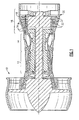
- Figure I illustrates selected portions of an example combustion engine 10, such as a gas turbine engine for an aircraft.
- the combustion engine 10 includes a compressor section 12, a combustor section 14, and a turbine section 16.
- the combustion engine 10 operates in a known manner, feeding compressed air or oxidizer from the compressor section 12 to the combustor section 14.
- the compressed air or oxidizer is mixed with fuel and reacts to produce a flow of hot gases 18.
- the turbine section 16 transforms the flow of hot gases 18 into mechanical energy to drive the compressor section 12.
- An exhaust nozzle 20 directs the hot gases 18 out of the combustion engine 10 to provide thrust to the aircraft or other vehicle.
- the turbine section 16 includes alternating rows of rotary airfoils or blades 22 and static airfoils or vanes 24.
- the vanes 24 are arranged in various stages, such a first stage, a second stage, a third stage, a fourth stage, etc.
- the blades 22 and vanes 24 are formed from a superalloy metal material, such as a cobalt or nickel superalloy in a casting, forging, or other known manufacturing process.
- the vane 24 includes a leading edge 36 and a trailing edge 38.
- the leading edge 36 is generally located toward the combustor section 14 and the trailing edge 38 is generally located toward the exhaust nozzle 20 in the combustion engine 10 ( Figure 1).
- the leading edge 36 and the trailing edge 38 define a chord width 40 of the vane 24.
- a thickness dimension 42 is transverse to the chordwidth 40.
- an aspect ratio of the chordwidth 40 to the thickness 42 at least partially determines an aerodynamic efficiency of the vane 24. That is, a relatively larger aspect ratio corresponds to a greater aerodynamic efficiency, while a relatively smaller aspect ratio corresponds to a lesser aerodynamic efficiency.
- the vane 24 includes an internal cavity 44 that extends towards the trailing edge 38 to define a slot 46.
- the slot 46 opens through the trailing edge 38.
- Pedestals 48 within the turbine vane 24 support a suction side 50 and a pressure side 52 of a vane 24.
- the internal cavity 44 and slot 46 reduce the weight of the vane 24 and allow internal cooling of the vane 24.
- Figure 3 shows a more detailed view of the section shown in Figure 2.
- the dotted line 54 represents an eroded surface of the trailing edge 38.
- the eroded surface 54 is the result of field operation of the combustion engine 10.
- a solid line 56 represents an original surface of the trailing edge 38.
- the original surface 56 refers to a shape and dimension of the trailing edge 38 before erosion.
- the original surface 56 may be the as-cast or as-forged condition of the trailing edge 38 of a newly manufactured vane 24.
- the original surface 56 is the as-designed dimension of the trailing edge 38 as found in a combustion engine 10 design manual.
- a portion 55 of the trailing edge 38 is removed by machining, grinding, grit blasting, or other known removal method, In the illustrated example, the portion 55 is removed to produce a relatively flat surface 70, which will serve as a substrate surface for depositing a laser cladding portion to rebuild the trailing edge 38 as described below.
- a laser cladding is deposited onto the relatively flat surface 70 to rebuild the trailing edge 38.
- a copper barrier member 72 is inserted into the slot 46 of the trailing edge 38.
- the copper barrier member 72 prevents filler material 74 ( Figure 5) that is used to rebuild the trailing edge 38 during the laser cladding process from entering the slot 46. This provides the benefit of eliminating the need for machining the slot 46 after the laser cladding process to restore the slot 46 shape.
- the copper barrier member 72 serves as a heat sink to remove heat (as indicated by the arrows 73) from the trailing edge 38 during the laser cladding process.
- the removal of heat through the copper barrier member 72 minimizes the size of the heat affected zone of the trailing edge 38 and thus reduces heat distortion, which is a problem with prior art welding and brazing methods.
- the filler material 74 is deposited onto the flat surface 70 in a known manner as a powder or other type of filler material to gradually buildup the trailing edge 38.
- the filler material is of a similar composition to the superalloy used to originally form the vane 24 to promote a strong bond between the cladding and the original superalloy of the vane 24.
- the filler material is a composition according to the standard set forth in AMS 5837.
- a laser consolidates (i.e., melts and fuses) the deposited filler material 74 in a known manner.
- the melting and fusing of the filler material 74 is relatively rapid and accurate, which provides the benefit of a fast vane 24 repair cycle time and a high degree of repeatability.
- laser cladding melts and fuses a relatively small trailing edge 38 and filler material 74 volume to minimize the size of the heat affected zone of the trailing edge, which is a drawback of prior art brazing and welding that result in relatively large heat affected zones.
- the consolidated filler material 74 builds-up on the trailing edge 38 to form an oversized cladded portion 76 that is bonded to the original superalloy material at the flat surface 70 of the vane 24.
- the oversized cladded portion 76 is larger than the original surface 56 in the chordwidth 40 dimension by an amount 78. This provides the benefit of ensuring that trailing edge 38 is built-up enough to completely restore the chordwidth 40 dimension to the original airfoil shape.
- the oversized cladded portion 76 is deposited on the trailing edge 38, the copper bearing member 72 is removed from the trailing edge 38.
- the oversized cladded portion 76 is machined to the chordwidth 40 dimension of the original surface 56.
- the machining includes known grinding, grit blasting, polishing, or other known machining method that provides a smooth transition area from the laser cladding to the original, non-repaired portions of the vane 24.
- the above example discloses a method for restoring the vane 24, or other turbine component.
- the trailing edge 38 of the vane 24 is eroded away during operation of the combustion engine 10, which reduces the aerodynamic efficiency of the turbine vane 24.
- the eroded portion of the trailing edge 38 is then removed and laser cladding is used to rebuild the trailing edge 38.
- the chordwidth dimension 40 of the vane 24 is restored to near its original dimension to increase the aerodynamic efficiency of the vane 24 and extend the life of the vane 24.
Landscapes
- Engineering & Computer Science (AREA)
- Mechanical Engineering (AREA)
- Physics & Mathematics (AREA)
- Optics & Photonics (AREA)
- Plasma & Fusion (AREA)
- General Engineering & Computer Science (AREA)
- Laser Beam Processing (AREA)
- Turbine Rotor Nozzle Sealing (AREA)
Abstract
Description
- This invention relates to repair of gas turbine engine components and, more particularly, to a method for restoring a chordwidth dimension of a turbine airfoil.
- Conventional gas turbine engines typically include turbine sections having an alternating arrangement of rotating turbine blades and static turbine vanes. A flow of hot gases from a combustor section expands against the turbine blades and vanes to rotationally drive the turbine blades, which are coupled to an engine main shaft that drives a compressor section.
- During engine operation, the hot gases produce a corrosive environment that corrosively attacks the surfaces of the blades and vanes and often results in corrosive pitting. The hot gases, soot from combustion, and particles within the flow of hot gases, also wear against the turbine blades and vanes and erode the surfaces of the blades, vanes, and other turbine engine components, which often changes the originally designed dimensions of the turbine engine components. The turbine vanes, for example, are formed in the shape of an airfoil and include a leading edge and a trailing edge that define a chordwidth there between. An aspect radio between the chordwidth and a thickness of the airfoil determines the aerodynamic efficiency of the turbine vane. Disadvantageously, the trailing edge of the turbine vane is susceptible to wear and erosion during turbine engine operation. As the trailing edge erodes, the length of the chordwidth dimension of the turbine vane decreases. Thus, the aspect ratio between the chordwidth and the airfoil thickness decreases, thereby decreasing the aerodynamic efficiency of the turbine vane.
- Conventional engine component repair techniques have been used to repair component microcracks, from fatigue for example, but are undesirable for several reasons. One conventional repair method includes brazing the engine component to repair the microcracks. Typically, brazing includes heating the engine component or relatively large zone of the engine component at high temperatures to melt a braze filler to fill the microcracks. The high temperatures may result in undesirable residual thermal stress in the engine component and undesirable changes in the metallic microstructure of the repaired areas.
- Accordingly, there is a need for a method of repairing a turbine airfoil along a chord width dimension to restore the airfoil to an original shape and prolong the useful life of the turbine airfoil without inducing high levels of residual stress.
- A method of restoring gas turbine engine component according to the present invention includes repairing a turbine airfoil along a chordwidth dimension to refurbish an eroded chordwidth dimension to a restored chordwidth dimension. Preferably this includes a step of removing an eroded portion of a trailing edge of the turbine airfoil and depositing a laser cladding to rebuild the shape of the trailing edge.
- In one exemplary method, the turbine airfoil includes a slot that extends through the trailing edge of the turbine airfoil. A barrier member is inserted into the slot during the laser cladding process to prevent laser cladding filler material from entering into the slot. The filler material is deposited next to the barrier member to reform a portion of the slot. During the laser cladding process, the barrier member also acts as a heat sink to remove heat from the rebuilt trailing edge of the turbine airfoil and minimize heat affected area.
- Accordingly, the disclosed example provides a method of refurbishing a trailing edge of a turbine airfoil to near the original chordwidth dimensions to recover aerodynamic efficiency.
- The various features and advantages of this invention will become apparent to those skilled in the art from the following detailed description of the currently preferred embodiment. The drawings that accompany the detailed description can be briefly described as follows.
- Figure 1 shows an example combustion engine.
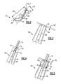
- Figure 2 shows an example cross-section of a turbine vane having a leading edge and a trailing edge.
- Figure 3 shows an eroded surface and an original surface of the trailing edge of the vane of Figure 2.
- Figure 4 shows removal of the eroded portion of the vane of Figure 3 and insertion of a barrier member into a slot through the trailing edge.
- Figure 5 shows rebuilding the trailing edge to produce an oversized cladded portion that is then machined down to produce a restored trailing edge having a chordwidth dimension near an original chordwidth dimension of the vane.
- Figure I illustrates selected portions of an
example combustion engine 10, such as a gas turbine engine for an aircraft. In this example, thecombustion engine 10 includes acompressor section 12, acombustor section 14, and aturbine section 16. Thecombustion engine 10 operates in a known manner, feeding compressed air or oxidizer from thecompressor section 12 to thecombustor section 14. The compressed air or oxidizer is mixed with fuel and reacts to produce a flow ofhot gases 18. Theturbine section 16 transforms the flow ofhot gases 18 into mechanical energy to drive thecompressor section 12. Anexhaust nozzle 20 directs thehot gases 18 out of thecombustion engine 10 to provide thrust to the aircraft or other vehicle. - In the illustrated example, the
turbine section 16 includes alternating rows of rotary airfoils orblades 22 and static airfoils orvanes 24. Thevanes 24 are arranged in various stages, such a first stage, a second stage, a third stage, a fourth stage, etc. Theblades 22 andvanes 24 are formed from a superalloy metal material, such as a cobalt or nickel superalloy in a casting, forging, or other known manufacturing process. - Referring to the
vane 24 cross section shown in Figure 2, thevane 24 includes a leadingedge 36 and atrailing edge 38. The leadingedge 36 is generally located toward thecombustor section 14 and thetrailing edge 38 is generally located toward theexhaust nozzle 20 in the combustion engine 10 (Figure 1). - The leading
edge 36 and thetrailing edge 38 define achord width 40 of thevane 24. Athickness dimension 42 is transverse to thechordwidth 40. In the illustrated example, an aspect ratio of thechordwidth 40 to thethickness 42 at least partially determines an aerodynamic efficiency of thevane 24. That is, a relatively larger aspect ratio corresponds to a greater aerodynamic efficiency, while a relatively smaller aspect ratio corresponds to a lesser aerodynamic efficiency. - The
vane 24 includes an internal cavity 44 that extends towards thetrailing edge 38 to define aslot 46. Theslot 46 opens through thetrailing edge 38.Pedestals 48 within the turbine vane 24 support asuction side 50 and a pressure side 52 of avane 24. The internal cavity 44 andslot 46 reduce the weight of thevane 24 and allow internal cooling of thevane 24. - Figure 3 shows a more detailed view of the section shown in Figure 2. In the illustrated example, the
dotted line 54 represents an eroded surface of thetrailing edge 38. In one example, theeroded surface 54 is the result of field operation of thecombustion engine 10. Asolid line 56 represents an original surface of thetrailing edge 38. Theoriginal surface 56 refers to a shape and dimension of thetrailing edge 38 before erosion. Thus, theoriginal surface 56 may be the as-cast or as-forged condition of thetrailing edge 38 of a newly manufacturedvane 24. Alternatively, theoriginal surface 56 is the as-designed dimension of thetrailing edge 38 as found in acombustion engine 10 design manual. - Over time, the friction of
hot gases 18 from thecombustor section 14, soot, or particles in thehot gas flow 18 erode away theoriginal surface 56 to produce theeroded surface 54. The erosion reduces thechordwidth 40 dimension by anamount 58, which reduces the aerodynamic efficiency of thevane 24 as described above. - Referring to Figure 4, to repair the
eroded surface 54 and restore theoriginal chordwidth 40, aportion 55 of thetrailing edge 38 is removed by machining, grinding, grit blasting, or other known removal method, In the illustrated example, theportion 55 is removed to produce a relativelyflat surface 70, which will serve as a substrate surface for depositing a laser cladding portion to rebuild thetrailing edge 38 as described below. - After removal of the
portion 55, a laser cladding is deposited onto the relativelyflat surface 70 to rebuild thetrailing edge 38. Before laser cladding, acopper barrier member 72 is inserted into theslot 46 of thetrailing edge 38. Thecopper barrier member 72 prevents filler material 74 (Figure 5) that is used to rebuild thetrailing edge 38 during the laser cladding process from entering theslot 46. This provides the benefit of eliminating the need for machining theslot 46 after the laser cladding process to restore theslot 46 shape. - Additionally, the
copper barrier member 72 serves as a heat sink to remove heat (as indicated by the arrows 73) from the trailingedge 38 during the laser cladding process. The removal of heat through thecopper barrier member 72 minimizes the size of the heat affected zone of the trailingedge 38 and thus reduces heat distortion, which is a problem with prior art welding and brazing methods. - Referring to Figure 5, the
filler material 74 is deposited onto theflat surface 70 in a known manner as a powder or other type of filler material to gradually buildup the trailingedge 38. In one example, the filler material is of a similar composition to the superalloy used to originally form thevane 24 to promote a strong bond between the cladding and the original superalloy of thevane 24. In another example, the filler material is a composition according to the standard set forth in AMS 5837. - A laser consolidates (i.e., melts and fuses) the deposited
filler material 74 in a known manner. The melting and fusing of thefiller material 74 is relatively rapid and accurate, which provides the benefit of afast vane 24 repair cycle time and a high degree of repeatability. Furthermore, laser cladding melts and fuses a relatively small trailingedge 38 andfiller material 74 volume to minimize the size of the heat affected zone of the trailing edge, which is a drawback of prior art brazing and welding that result in relatively large heat affected zones. - The
consolidated filler material 74 builds-up on the trailingedge 38 to form an oversized claddedportion 76 that is bonded to the original superalloy material at theflat surface 70 of thevane 24. The oversized claddedportion 76 is larger than theoriginal surface 56 in thechordwidth 40 dimension by anamount 78. This provides the benefit of ensuring that trailingedge 38 is built-up enough to completely restore thechordwidth 40 dimension to the original airfoil shape. - After the oversized cladded
portion 76 is deposited on the trailingedge 38, thecopper bearing member 72 is removed from the trailingedge 38. Next, the oversized claddedportion 76 is machined to thechordwidth 40 dimension of theoriginal surface 56. In one example, the machining includes known grinding, grit blasting, polishing, or other known machining method that provides a smooth transition area from the laser cladding to the original, non-repaired portions of thevane 24. - The above example discloses a method for restoring the
vane 24, or other turbine component. The trailingedge 38 of thevane 24 is eroded away during operation of thecombustion engine 10, which reduces the aerodynamic efficiency of theturbine vane 24. The eroded portion of the trailingedge 38 is then removed and laser cladding is used to rebuild the trailingedge 38. Thus, thechordwidth dimension 40 of thevane 24 is restored to near its original dimension to increase the aerodynamic efficiency of thevane 24 and extend the life of thevane 24. - Although a preferred embodiment of this invention has been disclosed, a worker of ordinary skill in this art would recognize that certain modifications would come within the scope of this invention. For that reason, the following claims should be studied to determine the true scope and content of this invention.
Claims (19)
- A method of restoring a gas turbine engine component (24), including the step of:(a) repairing a turbine airfoil (24) along a chordwidth dimension (40) to refurbish an eroded chordwidth dimension to a restored chordwidth dimension.
- The method as recited in Claim 1, wherein step (a) includes laser cladding a trailing edge (38) of the turbine airfoil (24) along the chordwidth dimension (40) with a filler material (74).
- The method of Claim 2, including step (b) inserting a barrier member (72) into a slot (46) in a trailing edge of the turbine airfoil (24) to prevent filler material (74) from entering the slot (46).
- The method as recited in Claim 3, including step (c) depositing the filler material (74) adjacent the barrier member (72) to extend a slot length of the slot (46).
- The method of Claim 3 or 4, further including the step of removing heat from the trailing edge (38) through the barrier member (72).
- The method of any of Claims 2 to 5, including step (b) machining the trailing edge (38) to form a substantially flat cladding surface before depositing the filler material (74).
- The method of any of Claims 2 to 6, wherein step (a) includes depositing the filler material (74) to produce an oversized chordwidth dimension (40) that is greater than the restored chordwidth dimension.
- The method of Claim 7, wherein step (a) includes machining the oversized chordwidth dimension to produce the restored chordwidth dimension.
- The method of any preceding claim, wherein the restored chordwidth dimension of step (a) is approximately an original chordwidth dimension of the turbine airfoil (24).
- A gas turbine engine including a compressor section (12), a combustion section (14), and a turbine section (16), the turbine section (16) having a turbine airfoil (24) restored according to the method recited in any preceding claim.
- A method of restoring a gas turbine engine component (24), comprising:(a) inserting a barrier member (72) into an opening (46) of a gas turbine engine turbine component (22);(b) depositing a filler material (74) near the opening (46); and(c) laser consolidating the filler material (74) to form a laser cladding portion (76).
- The method as recited in Claim 11, wherein the opening (46) of step (a) comprises a slot (46) and step (a) includes inserting a copper barrier member (72) into the slot (46).
- The method as recited in Claim 12, including step (d) removing heat from the laser cladding portion (76) through the barrier member (72).
- A gas turbine engine component (24) comprising:a turbine airfoil (24) having a leading edge (36) and a trailing edge (38), said trailing edge (38) having a laser cladding portion (76).
- The component of Claim 14, wherein said trailing edge (38) includes a slot (46) that defines a suction trailing edge side (50) and a pressure trailing edge side (52) opposite said suction trailing edge side (50).
- The component of Claim 15, wherein said laser cladding portion (76) includes a first laser cladding portion on said suction trailing edge side (50) and a second laser cladding portion on said pressure trailing edge side (52).
- The component of Claim 14, 15 or 16 wherein said trailing edge (38) includes a cast portion and a substantially flat interface (70) between said cast portion and said laser cladding portion (76).
- The component of any of Claim 14 to 17, wherein said laser cladding portion (76) comprises at least a portion of a chordwidth dimension of said turbine airfoil (24).
- A gas turbine engine including a compressor section (12), a combustion section (14), and a turbine section (16), said turbine section (16) including said turbine airfoil (24) as recited in any of Claims 14 to 18.
Applications Claiming Priority (1)
| Application Number | Priority Date | Filing Date | Title |
|---|---|---|---|
| SG200600245-5A SG134184A1 (en) | 2006-01-16 | 2006-01-16 | Chordwidth restoration of a trailing edge of a turbine airfoil by laser clad |
Publications (3)
| Publication Number | Publication Date |
|---|---|
| EP1808263A2 true EP1808263A2 (en) | 2007-07-18 |
| EP1808263A3 EP1808263A3 (en) | 2010-05-19 |
| EP1808263B1 EP1808263B1 (en) | 2016-04-13 |
Family
ID=37908147
Family Applications (1)
| Application Number | Title | Priority Date | Filing Date |
|---|---|---|---|
| EP07250144.8A Active EP1808263B1 (en) | 2006-01-16 | 2007-01-15 | Chordwidth restoration of a trailing edge of a turbine airfoil by laser clad |
Country Status (4)
| Country | Link |
|---|---|
| US (1) | US9017024B2 (en) |
| EP (1) | EP1808263B1 (en) |
| JP (1) | JP2007192218A (en) |
| SG (1) | SG134184A1 (en) |
Families Citing this family (7)
| Publication number | Priority date | Publication date | Assignee | Title |
|---|---|---|---|---|
| US20080017280A1 (en) * | 2006-07-18 | 2008-01-24 | United Technologies Corporation | Process for repairing turbine engine components |
| SG165202A1 (en) * | 2009-03-25 | 2010-10-28 | United Technologies Corp | Method and apparatus for cleaning a component using microwave radiation |
| US9303517B2 (en) * | 2012-06-15 | 2016-04-05 | General Electric Company | Channel marker and related methods |
| US10010937B2 (en) * | 2015-11-09 | 2018-07-03 | General Electric Company | Additive manufacturing method for making overhanging tabs in cooling holes |
| US10370979B2 (en) | 2015-11-23 | 2019-08-06 | United Technologies Corporation | Baffle for a component of a gas turbine engine |
| WO2017123995A1 (en) * | 2016-01-14 | 2017-07-20 | Arconic Inc. | Methods for producing forged products and other worked products |
| US10815782B2 (en) | 2016-06-24 | 2020-10-27 | General Electric Company | Methods for repairing airfoil trailing edges to include ejection slots therein |
Citations (1)
| Publication number | Priority date | Publication date | Assignee | Title |
|---|---|---|---|---|
| US6269540B1 (en) | 1998-10-05 | 2001-08-07 | National Research Council Of Canada | Process for manufacturing or repairing turbine engine or compressor components |
Family Cites Families (26)
| Publication number | Priority date | Publication date | Assignee | Title |
|---|---|---|---|---|
| US4394879A (en) * | 1981-06-08 | 1983-07-26 | Reynolds William A | Method of repairing damaged keyway |
| US5142778A (en) * | 1991-03-13 | 1992-09-01 | United Technologies Corporation | Gas turbine engine component repair |
| US5584663A (en) * | 1994-08-15 | 1996-12-17 | General Electric Company | Environmentally-resistant turbine blade tip |
| US6173491B1 (en) * | 1999-08-12 | 2001-01-16 | Chromalloy Gas Turbine Corporation | Method for replacing a turbine vane airfoil |
| US6154959A (en) * | 1999-08-16 | 2000-12-05 | Chromalloy Gas Turbine Corporation | Laser cladding a turbine engine vane platform |
| US6238187B1 (en) * | 1999-10-14 | 2001-05-29 | Lsp Technologies, Inc. | Method using laser shock peening to process airfoil weld repairs pertaining to blade cut and weld techniques |
| US20020142107A1 (en) * | 2000-07-27 | 2002-10-03 | Jyoti Mazumder | Fabrication of customized, composite, and alloy-variant components using closed-loop direct metal deposition |
| JP2003206748A (en) * | 2002-01-15 | 2003-07-25 | Mitsubishi Heavy Ind Ltd | Repair method and repaired high-temperature part of peripheral wall of cooling hole of high-temperature part |
| US6742698B2 (en) | 2002-06-10 | 2004-06-01 | United Technologies Corporation | Refractory metal backing material for weld repair |
| EP1396556A1 (en) * | 2002-09-06 | 2004-03-10 | ALSTOM (Switzerland) Ltd | Method for controlling the microstructure of a laser metal formed hard layer |
| US7216428B2 (en) * | 2003-03-03 | 2007-05-15 | United Technologies Corporation | Method for turbine element repairing |
| US7009137B2 (en) * | 2003-03-27 | 2006-03-07 | Honeywell International, Inc. | Laser powder fusion repair of Z-notches with nickel based superalloy powder |
| DE10316966A1 (en) * | 2003-04-12 | 2004-10-28 | Rolls-Royce Deutschland Ltd & Co Kg | Procedure for the reconstruction of flat, damaged components |
| US7146725B2 (en) * | 2003-05-06 | 2006-12-12 | Siemens Power Generation, Inc. | Repair of combustion turbine components |
| US7028881B2 (en) * | 2003-09-18 | 2006-04-18 | Siemens Power Generation, Inc. | Method for providing removable weld backing |
| US20050178750A1 (en) * | 2004-02-13 | 2005-08-18 | Kenny Cheng | Repair of article by laser cladding |
| US7316850B2 (en) * | 2004-03-02 | 2008-01-08 | Honeywell International Inc. | Modified MCrAlY coatings on turbine blade tips with improved durability |
| US6972390B2 (en) * | 2004-03-04 | 2005-12-06 | Honeywell International, Inc. | Multi-laser beam welding high strength superalloys |
| US20050217110A1 (en) * | 2004-04-06 | 2005-10-06 | Topal Valeriy I | Deposition repair of hollow items |
| US20060067830A1 (en) * | 2004-09-29 | 2006-03-30 | Wen Guo | Method to restore an airfoil leading edge |
| US7472478B2 (en) * | 2004-10-29 | 2009-01-06 | Honeywell International Inc. | Adaptive machining and weld repair process |
| US7966707B2 (en) * | 2005-05-06 | 2011-06-28 | United Technologies Corporation | Method for repairing superalloy components using inserts |
| US20060248718A1 (en) * | 2005-05-06 | 2006-11-09 | United Technologies Corporation | Superalloy repair methods and inserts |
| US20070044306A1 (en) * | 2005-08-29 | 2007-03-01 | United Technologies Corporation | Superalloy repair methods |
| SG134183A1 (en) * | 2006-01-16 | 2007-08-29 | United Technologies Corp | Turbine component trailing edge and platform restoration by laser cladding |
| SG134185A1 (en) * | 2006-01-16 | 2007-08-29 | United Technologies Corp | Turbine platform repair using laser clad |
-
2006
- 2006-01-16 SG SG200600245-5A patent/SG134184A1/en unknown
- 2006-03-23 US US11/388,084 patent/US9017024B2/en not_active Expired - Fee Related
- 2006-12-19 JP JP2006340698A patent/JP2007192218A/en active Pending
-
2007
- 2007-01-15 EP EP07250144.8A patent/EP1808263B1/en active Active
Patent Citations (1)
| Publication number | Priority date | Publication date | Assignee | Title |
|---|---|---|---|---|
| US6269540B1 (en) | 1998-10-05 | 2001-08-07 | National Research Council Of Canada | Process for manufacturing or repairing turbine engine or compressor components |
Also Published As
| Publication number | Publication date |
|---|---|
| US20070163113A1 (en) | 2007-07-19 |
| US9017024B2 (en) | 2015-04-28 |
| EP1808263B1 (en) | 2016-04-13 |
| EP1808263A3 (en) | 2010-05-19 |
| JP2007192218A (en) | 2007-08-02 |
| SG134184A1 (en) | 2007-08-29 |
Similar Documents
| Publication | Publication Date | Title |
|---|---|---|
| US20150361796A1 (en) | Turbine platform repair using laser clad | |
| US7966707B2 (en) | Method for repairing superalloy components using inserts | |
| US8356409B2 (en) | Repair method for gas turbine engine components | |
| US5822852A (en) | Method for replacing blade tips of directionally solidified and single crystal turbine blades | |
| JP4301402B2 (en) | How to repair a gas turbine engine stationary shroud using laser cladding | |
| US5846057A (en) | Laser shock peening for gas turbine engine weld repair | |
| CN101053897B (en) | Repair of hpt schrouds with sintered preforms | |
| JP2007192223A (en) | Rehabilitation of trailing edge and platform of turbine part by laser cladding | |
| EP1808263B1 (en) | Chordwidth restoration of a trailing edge of a turbine airfoil by laser clad | |
| EP1563945A2 (en) | Repair of article by laser cladding | |
| EP2947266B1 (en) | Methods of repairing integrally bladed rotors | |
| US9121282B2 (en) | Methods for the controlled reduction of turbine nozzle flow areas and turbine nozzle components having reduced flow areas | |
| US20070157447A1 (en) | Method of improving the properties of a repaired component and a component improved thereby | |
| EP1227218A2 (en) | Turbine nozzle segment and method of repairing same | |
| EP1422381B1 (en) | Method of repairing a turbine nozzle segment, and turbine nozzle segment | |
| EP1965023A2 (en) | Repaired vane assemblies and methods of repairing vane assemblies | |
| EP1416063A1 (en) | Method of repairing a stationary shroud of a gas turbine engine using plasma transferred arc welding | |
| US9700941B2 (en) | Method for repairing a component for use in a turbine engine | |
| JP2006177363A (en) | Repair method for gas turbine blade tip without recoating of repair blade tip | |
| EP2412930B1 (en) | Turbine nozzle segment and method of repairing same | |
| EP3927943B1 (en) | Tip repair of a turbine component using a composite tip boron base pre-sintered preform | |
| EP1491720A1 (en) | Method for improving the wear resistance of a support region between a turbine outer case and a supported turbine vane |
Legal Events
| Date | Code | Title | Description |
|---|---|---|---|
| PUAI | Public reference made under article 153(3) epc to a published international application that has entered the european phase |
Free format text: ORIGINAL CODE: 0009012 |
|
| AK | Designated contracting states |
Kind code of ref document: A2 Designated state(s): AT BE BG CH CY CZ DE DK EE ES FI FR GB GR HU IE IS IT LI LT LU LV MC NL PL PT RO SE SI SK TR |
|
| AX | Request for extension of the european patent |
Extension state: AL BA HR MK YU |
|
| PUAL | Search report despatched |
Free format text: ORIGINAL CODE: 0009013 |
|
| AK | Designated contracting states |
Kind code of ref document: A3 Designated state(s): AT BE BG CH CY CZ DE DK EE ES FI FR GB GR HU IE IS IT LI LT LU LV MC NL PL PT RO SE SI SK TR |
|
| AX | Request for extension of the european patent |
Extension state: AL BA HR MK RS |
|
| RIC1 | Information provided on ipc code assigned before grant |
Ipc: B23K 26/34 20060101ALN20100415BHEP Ipc: F01D 5/00 20060101ALI20100415BHEP Ipc: B23P 6/00 20060101AFI20100415BHEP Ipc: B23K 37/06 20060101ALN20100415BHEP |
|
| 17P | Request for examination filed |
Effective date: 20101119 |
|
| AKX | Designation fees paid |
Designated state(s): DE GB |
|
| 17Q | First examination report despatched |
Effective date: 20130925 |
|
| REG | Reference to a national code |
Ref country code: DE Ref legal event code: R079 Ref document number: 602007045750 Country of ref document: DE Free format text: PREVIOUS MAIN CLASS: B23K0026340000 Ipc: B23P0006000000 |
|
| GRAP | Despatch of communication of intention to grant a patent |
Free format text: ORIGINAL CODE: EPIDOSNIGR1 |
|
| RIC1 | Information provided on ipc code assigned before grant |
Ipc: B23K 26/32 20140101ALI20150227BHEP Ipc: B23K 37/06 20060101ALN20150227BHEP Ipc: F01D 5/00 20060101ALI20150227BHEP Ipc: B23P 6/00 20060101AFI20150227BHEP Ipc: B23K 26/34 20140101ALN20150227BHEP |
|
| RIC1 | Information provided on ipc code assigned before grant |
Ipc: B23P 6/00 20060101AFI20150306BHEP Ipc: B23K 37/06 20060101ALN20150306BHEP Ipc: B23K 26/32 20140101ALI20150306BHEP Ipc: F01D 5/00 20060101ALI20150306BHEP Ipc: B23K 26/34 20140101ALN20150306BHEP |
|
| INTG | Intention to grant announced |
Effective date: 20150324 |
|
| GRAP | Despatch of communication of intention to grant a patent |
Free format text: ORIGINAL CODE: EPIDOSNIGR1 |
|
| INTG | Intention to grant announced |
Effective date: 20151009 |
|
| GRAS | Grant fee paid |
Free format text: ORIGINAL CODE: EPIDOSNIGR3 |
|
| GRAA | (expected) grant |
Free format text: ORIGINAL CODE: 0009210 |
|
| AK | Designated contracting states |
Kind code of ref document: B1 Designated state(s): DE GB |
|
| REG | Reference to a national code |
Ref country code: GB Ref legal event code: FG4D |
|
| REG | Reference to a national code |
Ref country code: DE Ref legal event code: R081 Ref document number: 602007045750 Country of ref document: DE Owner name: UNITED TECHNOLOGIES CORP. (N.D.GES.D. STAATES , US Free format text: FORMER OWNER: UNITED TECHNOLOGIES CORP. (N.D.GES.D. STAATES DELAWARE), HARTFORD, CONN., US |
|
| REG | Reference to a national code |
Ref country code: DE Ref legal event code: R096 Ref document number: 602007045750 Country of ref document: DE |
|
| RAP2 | Party data changed (patent owner data changed or rights of a patent transferred) |
Owner name: UNITED TECHNOLOGIES CORPORATION |
|
| REG | Reference to a national code |
Ref country code: DE Ref legal event code: R097 Ref document number: 602007045750 Country of ref document: DE |
|
| PLBE | No opposition filed within time limit |
Free format text: ORIGINAL CODE: 0009261 |
|
| STAA | Information on the status of an ep patent application or granted ep patent |
Free format text: STATUS: NO OPPOSITION FILED WITHIN TIME LIMIT |
|
| 26N | No opposition filed |
Effective date: 20170116 |
|
| REG | Reference to a national code |
Ref country code: DE Ref legal event code: R082 Ref document number: 602007045750 Country of ref document: DE Representative=s name: SCHMITT-NILSON SCHRAUD WAIBEL WOHLFROM PATENTA, DE |
|
| REG | Reference to a national code |
Ref country code: DE Ref legal event code: R082 Ref document number: 602007045750 Country of ref document: DE Representative=s name: SCHMITT-NILSON SCHRAUD WAIBEL WOHLFROM PATENTA, DE Ref country code: DE Ref legal event code: R081 Ref document number: 602007045750 Country of ref document: DE Owner name: UNITED TECHNOLOGIES CORP. (N.D.GES.D. STAATES , US Free format text: FORMER OWNER: UNITED TECHNOLOGIES CORPORATION, HARTFORD, CONN., US |
|
| PGFP | Annual fee paid to national office [announced via postgrant information from national office to epo] |
Ref country code: DE Payment date: 20211215 Year of fee payment: 16 |
|
| REG | Reference to a national code |
Ref country code: DE Ref legal event code: R081 Ref document number: 602007045750 Country of ref document: DE Owner name: RAYTHEON TECHNOLOGIES CORPORATION (N.D.GES.D.S, US Free format text: FORMER OWNER: UNITED TECHNOLOGIES CORP. (N.D.GES.D. STAATES DELAWARE), FARMINGTON, CONN., US |
|
| REG | Reference to a national code |
Ref country code: DE Ref legal event code: R119 Ref document number: 602007045750 Country of ref document: DE |
|
| PG25 | Lapsed in a contracting state [announced via postgrant information from national office to epo] |
Ref country code: DE Free format text: LAPSE BECAUSE OF NON-PAYMENT OF DUE FEES Effective date: 20230801 |
|
| PGFP | Annual fee paid to national office [announced via postgrant information from national office to epo] |
Ref country code: GB Payment date: 20241219 Year of fee payment: 19 |
|
| P01 | Opt-out of the competence of the unified patent court (upc) registered |
Free format text: CASE NUMBER: UPC_APP_0018168_1808263/2025 Effective date: 20251218 |