EP1808088A1 - Modular snow travel system for common footwear - Google Patents
Modular snow travel system for common footwear Download PDFInfo
- Publication number
- EP1808088A1 EP1808088A1 EP07000618A EP07000618A EP1808088A1 EP 1808088 A1 EP1808088 A1 EP 1808088A1 EP 07000618 A EP07000618 A EP 07000618A EP 07000618 A EP07000618 A EP 07000618A EP 1808088 A1 EP1808088 A1 EP 1808088A1
- Authority
- EP
- European Patent Office
- Prior art keywords
- traction
- snowdeck
- heel
- slider
- overboot
- Prior art date
- Legal status (The legal status is an assumption and is not a legal conclusion. Google has not performed a legal analysis and makes no representation as to the accuracy of the status listed.)
- Granted
Links
- 230000007246 mechanism Effects 0.000 claims abstract description 48
- 210000002683 foot Anatomy 0.000 claims description 21
- 125000006850 spacer group Chemical group 0.000 claims description 13
- 210000004744 fore-foot Anatomy 0.000 claims description 10
- 210000000078 claw Anatomy 0.000 claims description 9
- 230000003213 activating effect Effects 0.000 claims description 4
- 230000037431 insertion Effects 0.000 claims 3
- 238000003780 insertion Methods 0.000 claims 3
- 238000007789 sealing Methods 0.000 claims 2
- 239000000463 material Substances 0.000 description 9
- 230000008901 benefit Effects 0.000 description 3
- 230000008595 infiltration Effects 0.000 description 3
- 238000001764 infiltration Methods 0.000 description 3
- 239000002184 metal Substances 0.000 description 3
- XLYOFNOQVPJJNP-UHFFFAOYSA-N water Substances O XLYOFNOQVPJJNP-UHFFFAOYSA-N 0.000 description 3
- 230000000295 complement effect Effects 0.000 description 2
- 238000009413 insulation Methods 0.000 description 2
- 239000007769 metal material Substances 0.000 description 2
- 239000000356 contaminant Substances 0.000 description 1
- 230000009977 dual effect Effects 0.000 description 1
- 230000000694 effects Effects 0.000 description 1
- 229920001971 elastomer Polymers 0.000 description 1
- 239000012774 insulation material Substances 0.000 description 1
- 210000000452 mid-foot Anatomy 0.000 description 1
- 230000004048 modification Effects 0.000 description 1
- 238000012986 modification Methods 0.000 description 1
- 229920001084 poly(chloroprene) Polymers 0.000 description 1
- 230000002787 reinforcement Effects 0.000 description 1
- 229910001220 stainless steel Inorganic materials 0.000 description 1
- 239000010935 stainless steel Substances 0.000 description 1
- 230000000153 supplemental effect Effects 0.000 description 1
- 230000007704 transition Effects 0.000 description 1
Images




Classifications
-
- A—HUMAN NECESSITIES
- A43—FOOTWEAR
- A43C—FASTENINGS OR ATTACHMENTS OF FOOTWEAR; LACES IN GENERAL
- A43C15/00—Non-skid devices or attachments
- A43C15/06—Ice-gripping devices or attachments, e.g. ice-spurs, ice-cleats, ice-creepers, crampons; Climbing devices or attachments, e.g. mountain climbing irons
- A43C15/061—Ice-gripping devices or attachments, e.g. ice-cleats, ice-creepers
- A43C15/063—Ice-gripping devices or attachments, e.g. ice-cleats, ice-creepers with ice-gripping means projecting from the front foot region
-
- A—HUMAN NECESSITIES
- A43—FOOTWEAR
- A43B—CHARACTERISTIC FEATURES OF FOOTWEAR; PARTS OF FOOTWEAR
- A43B5/00—Footwear for sporting purposes
- A43B5/18—Attachable overshoes for sporting purposes
-
- A—HUMAN NECESSITIES
- A43—FOOTWEAR
- A43C—FASTENINGS OR ATTACHMENTS OF FOOTWEAR; LACES IN GENERAL
- A43C15/00—Non-skid devices or attachments
- A43C15/06—Ice-gripping devices or attachments, e.g. ice-spurs, ice-cleats, ice-creepers, crampons; Climbing devices or attachments, e.g. mountain climbing irons
- A43C15/061—Ice-gripping devices or attachments, e.g. ice-cleats, ice-creepers
- A43C15/065—Ice-gripping devices or attachments, e.g. ice-cleats, ice-creepers with ice-gripping means projecting from the region directly in front of the heel
-
- A—HUMAN NECESSITIES
- A43—FOOTWEAR
- A43C—FASTENINGS OR ATTACHMENTS OF FOOTWEAR; LACES IN GENERAL
- A43C15/00—Non-skid devices or attachments
- A43C15/06—Ice-gripping devices or attachments, e.g. ice-spurs, ice-cleats, ice-creepers, crampons; Climbing devices or attachments, e.g. mountain climbing irons
- A43C15/061—Ice-gripping devices or attachments, e.g. ice-cleats, ice-creepers
- A43C15/066—Ice-gripping devices or attachments, e.g. ice-cleats, ice-creepers with ice-gripping means projecting from the heel area, e.g. ice spurs
-
- A—HUMAN NECESSITIES
- A43—FOOTWEAR
- A43C—FASTENINGS OR ATTACHMENTS OF FOOTWEAR; LACES IN GENERAL
- A43C15/00—Non-skid devices or attachments
- A43C15/06—Ice-gripping devices or attachments, e.g. ice-spurs, ice-cleats, ice-creepers, crampons; Climbing devices or attachments, e.g. mountain climbing irons
- A43C15/068—Climbing devices or attachments, e.g. glacier crampons, mountain climbing irons
-
- A—HUMAN NECESSITIES
- A63—SPORTS; GAMES; AMUSEMENTS
- A63C—SKATES; SKIS; ROLLER SKATES; DESIGN OR LAYOUT OF COURTS, RINKS OR THE LIKE
- A63C13/00—Snow shoes
- A63C13/003—Means thereof for preventing slipping, e.g. crampons, e.g. on frame or shoe plate
-
- A—HUMAN NECESSITIES
- A63—SPORTS; GAMES; AMUSEMENTS
- A63C—SKATES; SKIS; ROLLER SKATES; DESIGN OR LAYOUT OF COURTS, RINKS OR THE LIKE
- A63C13/00—Snow shoes
- A63C13/006—Shoe support thereof, e.g. plate, movable relative to the frame
-
- A—HUMAN NECESSITIES
- A63—SPORTS; GAMES; AMUSEMENTS
- A63C—SKATES; SKIS; ROLLER SKATES; DESIGN OR LAYOUT OF COURTS, RINKS OR THE LIKE
- A63C13/00—Snow shoes
- A63C13/005—Frames therefor
Definitions
- snowdeck Independently of such cleated overboots, for use in deep snow or where greater stability is required a snowdeck has also been used. Such snowdeck could be attached to the user's footwear and would be of enlarged size to facilitate walking in deep snow.
- An object of this invention is to provide an improved system for securing footing on a variety of slippery surfaces.
- a further object of this invention is to provide such a system which includes a first traction component having the capability of itself providing secure footing on various surfaces, but also having the capability of being mounted to a snowdeck to increase the secure footing.
- the first traction component includes at least one traction cleat.
- the system also includes a snowdeck which preferably has a releasable locking mechanism for selective engagement with the traction cleat so that the traction cleat has the dual function of assisting in providing secure footing when the first traction component is used alone or for acting as structure to mount the first traction component to the snowdeck.
- the releasable locking mechanism includes a catch which would be engaged by an exposed latch in the form of a protrusion or cutout/hole or hook structure on the traction cleat.
- the locking mechanism also includes a member for activating the catch to selectively engage/disengage the cleat.
- the catch is in the form of a rod mounted on a longitudinal slider.
- the activating member is secured to a transverse slider which has a cam face disposed against a cam face of the longitudinal slider. Sideways movement of the transverse slider controls the longitudinal movement or positioning of the longitudinal slider. In this manner the catch can be moved to and from its engaging position and its disengaging position.
- the first traction component may be an overboot which has sets of traction cleats disposed on the lower surface of its sole with the traction cleat that engages the snowdeck being located on the forefoot region of the overboot.
- the improved system also includes novel heel structure which prevents cleats on the traction component from damaging the snowdeck.
- the present invention is directed to providing a modular snow travel system for common footwear.
- a first flexible or inflexible traction component is provided which is adapted to be attached to conventional footwear such as running shoes or other types of footwear or to the foot itself.
- the first traction component could be an overboot which will be described with greater particularity or could simply be some form of binding assembly that could be attached to the footwear or the foot and fulfill all the other basic functions required of the first traction component and would be secured only in part over the footwear or foot.
- the first traction component has at least one traction cleat attached thereto, preferably in the forefoot region, so as to provide improved traction when walking or running on ice, snow or other slippery surfaces.
- a snowdeck is also provided that includes a locking mechanism adapted to secure to at least one of the cleats of the first traction component and attach it to the snowdeck.
- the attachment to the snowdeck allows for the first traction component to pivot relative to the snowdeck to allow for ease in walking or running.
- the snowdeck includes additional traction cleats or claws attached thereto.
- the present invention provides a number of improved first traction components that are adapted to attach to a wide variety of conventional footwear styles, including boots, shoes, and running shoes or to the foot.
- the first traction components include one or more buckle systems to allow for quick attachment to and removal from the foot/footwear.
- These various forms of first traction components provide greatly improved traction for the wearer while also providing additional benefits, such as with the overboot embodiments that provide improved insulation and protection from snow, dirt, or water infiltration of the footwear.
- Traction cleats may be provided on the forefoot, rear-foot, or mid-foot of the first traction component, or any combination thereof.
- the various embodiments of the snowdecks allow for easy step-in addition of additional floatation and/or greater stability for the wearer.
- at least one of the traction cleats of the first traction component is adapted to "click in” to a binding or locking mechanism on the snowdeck.
- the locking mechanism allows for quick disengaging of the first traction component.
- the wearer can leave the first traction component attached to the snowdeck and convert between conventional footwear and something akin to a conventional snowshoe configuration.
- Various snowdeck configurations and binding systems may be used within the scope of the present invention.
- FIG. 1 a first traction component, which in Figure 1 is in the form of an overboot 12, is detachably mounted to a snowdeck 14.
- overboot 12 can include structure to facilitate a wearer readily inserting the wearer's foot into the overboot 12. This can be done by slipping the foot and any footwear into the opening 16 at the top of the overboot 12. Opening 16 can be increased in size by providing, for example, a zipper 18 having a slider 20 on the back of overboot 12.
- the front of the footwear could include a flap 22 that could be opened and then later closed and held in the closed condition through any suitable fastening arrangement such as illustrated by strap structure 24 and fastener structure, such as ratchet 26. It is to be understood that these forms of enlarging the opening 16 may vary in any conventional manner.
- the front opening 16 may be additionally secured through use of supplemental closure devices, such as hook-and-loop fasteners, latches, laces, zippers, or the like, that can both aid in more securely holding the overboot 12 to the wearer and to assist in reducing snow, dirt or water infiltration into the overboot 12.
- supplemental closure devices such as hook-and-loop fasteners, latches, laces, zippers, or the like, that can both aid in more securely holding the overboot 12 to the wearer and to assist in reducing snow, dirt or water infiltration into the overboot 12.
- overboot 12 an advantageous feature of overboot 12 is the inclusion of a loop 23 on each side of the overboot which slides through a strap loop 25 allowing for the precise placement of the strap structure 24 to be adjusted up or down the boot to accommodate laces hot spots.
- the strap structure 24 also includes a series of transverse teeth 27 which cooperate with ratchet 26 for providing the adjustability of the opening 16 of overboot 12.
- the lower surface of the sole 28 of overboot 12 includes sets of cleats located at any suitable location in order to provide the desired traction to secure footing on a slippery surface.
- Such sets of cleats are preferably around the periphery of the sole 28 and could include cleats 30 as illustrated located at the toe and heel portions of sole 28. Additional sets of cleats 32, 34 and 36 also extend from the sole.
- the cleats on one longitudinal side of overboot 12 are mirror images of those on the other longitudinal side.
- each traction cleat includes a latch in the form of a cutout forming an exposed hook portion 38 facing toward the toe, for purposes later described.
- Other forms of latch structure could also be used instead of an exposed hook portion. Examples of such latch structure include various shaped cutouts or holes or any other form of opening which would be engaged by a catch on the snowdeck, as later described.
- the latch could also be an exposed protrusion on the cleat 36 for engagement with a catch on the snowdeck.
- overboot 12 could be lined with any suitable insulation material 27 to provide insulation and protection from snow, dirt or water infiltration of the footwear.
- the overboot itself would be made of materials conventionally used in snow conditions.
- overboot 12 is made of neoprene.
- the sole of the overboot is preferably textured as illustrated in provisional application Serial No. 60/758,890 .
- the cleats are made of a suitable metal material, such as stainless steel.
- the material used for the overboot upper is stretchy with reinforcement material strategically attached to the stretchy material for durability, to provide a means for buckle attachment for a non-stretchy (i.e., secure) strap harness and as a support.
- the metal cleats could be co-molded with the rubber outsole.
- snowdeck 14 comprises a frame 40 which may be made of any suitable material such as a metal material conventionally used for snowdecks.
- Frame 40 has a generally flat portion which receives the overboot and may be inclined upwardly forwardly of where the user's foot (overboot) would be located.
- Any suitable decking material 42 spans the frame leaving openings as necessary or desired.
- various sets of cleats or claws 44 are provided on the bottom of the decking 42 to further enhance traction for use on slippery surfaces and in deep snow.
- the claws 44 may be provided at any suitable locations and may be secured to webbing 42 in any suitable manner.
- the claws on one longitudinal side of the snowdeck 14 are mirror images of those on the other side.
- a heel block 46 is mounted to a heel pad or support 48 provided on decking 42. Heel block 46 would be located between the sets of claws 44 located in the heel portion and would be of sufficient height to be surrounded by and generally elevate the overboot cleats 30,34 above decking 42 so as to not damage the decking when the overboot is mounted to the snowdeck by minimizing any digging of the cleats into the decking.
- the spacer aspect of the heel block may maintain the cleats generally out of contact but could permit some contact as long as damage to the decking is minimized.
- heel block 42 could include some form of catch, such as pins which may be selectively extended from the heel block, for engagement by the hook portion 38 of the cleats 34.
- the first traction component e.g. overboot 12
- the first traction component e.g. overboot 12
- the first traction component e.g. overboot 12
- the first traction component e.g. overboot 12
- the first traction component e.g. overboot 12
- the term “snowdeck” is not intended to be limited to conventional snowdecks but could include various types of devices for attachment to the feet to assist movement in snow, such as snowshoes, skis or the like.
- Heel block 46 may be mounted on the heel area decking 42 by being secured to the heel pad or support member 48 which contains a longitudinal slot 50 and two sets of transverse slots 52,52. See Figure 6. This permits the location of heel block 46 to be varied for accommodating different size overboots.
- heel block 46 could include engaging members detachably mounted in the front set of slots 52 to lock it in place or heel block 46 could be moved rearwardly in slot 50 and then engaged in rearward slots 52 where a larger size overboot is used.
- a spacer such as heel block 46 to generally elevate the cleats of the traction component from the snowdeck 14 is a distinct advantage over prior arrangements.
- a spacer assures that the cleats of a traction system in the heel area are prevented from generally contacting the snowshoe deck.
- Such spacer in the preferred form is a heel block, such as heel block 46 mounted directly to the snowdeck 14.
- the concept of a spacer may also be practiced where, for example, the spacer is mounted (such as being detachably mounted) to the traction device or traction component so that it provides a spacing member of sufficient thickness to generally elevate the cleats from the snowshoe deck.
- the provision of such a spacer is advantageous over prior arrangements using, for example, cutouts in the snowshoe deck to avoid contact by the cleats of the traction system.
- a key feature of this invention is the provision of a releasable locking mechanism 56 for selectively engaging the first traction component, such as overboot 12, with the snowdeck 14.
- the components of the releasable locking mechanism 56 are best shown in Figures 9-10 and its manner of operation is best illustrated in Figures 11-15.
- each cleat 36,36 is individually mounted to the sole 28 of overboot 12 by, for example, being embedded in an elastomeric mounting member which in turn is secured to the bottom of sole 28.
- cleats 36,36 and toe cleats 30,30 may be mounted to a common plate by being downward extensions of a plate 54 which would be incorporated in the sole 28 of overboot 12, such as illustrated in provisional application Serial No. 60/758,890 .
- the invention could also be practiced where the cleats, particularly the cleats 36, are simply part of a binding that would be secured to conventional footwear and need not necessarily be part of an overboot.
- Figure 9 also illustrates the components of the releasable locking mechanism 56 that are incorporated in the snowdeck 14. These components include a plate 58 made of any suitable material such as metal which could have downwardly extending projections that form the claws 44. Plate 58 includes a pair of elongated slots 60 of a size and location to receive the cleats 3G,36.
- Gasket 62 mounted beneath the plate 58 which covers housing 64 in order to reduce snow or other contaminants infiltrating the locking mechanism.
- Gasket 62 is also provided with a pair of elongated slits 66 aligned with slots 60 of plate 58 so that the cleats 36 also extend through gasket 62.
- the slits 66 create a seal below slots 60 to minimize snow entering and contaminating the click-in locking mechanism.
- housing 64 includes a longitudinally movable slider 68 and a transversely movable slider 70 which fit in an appropriately shaped recess 72 of housing 64.
- Longitudinal slider 68 includes a groove 76 which receives a fastening rod 78 the ends of which would abut against walls 80,80 in housing 64.
- a pair of springs 82,82 are provided in housing 80.
- Longitudinal slider 68 has a pair of legs 84,84 which fit in appropriate recesses 86,86 in housing 64 when slider 68 is mounted in housing 64.
- Longitudinal slider 88 has a cam wall which includes a pair of projecting surfaces 90 and an intermediate recess 92.
- transverse slider 70 has a complementary cam wall which includes projections 94,94 and intermediate recess 96.
- the projections 90,90 of slider 68 and 94,94 of slider 70 preferably terminate in flat portions.
- a release/actuation member, such as a pull cord 98 is also provided in transverse slider 70.
- Pull cord 98 is fixedly mounted to sleeve 100 located in a notched portion of slider 70.
- one end of pull cord 98 may have a handle 102 attached to that end, while the other end may have a handle 104.
- the handles may take any suitable form such as handle 102 being in the form of a block having grooves or ridges to facilitate gripping or could be a loop such as illustrated for handle 104.
- the pull cord is made of a strong, yet bendable material such as a braided metal wire.
- a strong, yet bendable material such as a braided metal wire.
- Other suitable materials could be used and, although not as preferred, the pull cord itself could be a stiff non-bendable member since the main requirement is that it have sufficient strength to be pulled in a transverse direction and that it is coupled to the transverse slider so that the lateral pulling is transmitted to the transverse slider to cause the transverse slider to shift back and forth to and from its locking and unlocking conditions.
- Figures 11-13 illustrate the condition of the locking mechanism when in the disengaged or the about to be engaged position.
- handle or loop 104 has been pulled to move slider 70 toward the left.
- the cam faces of slider 70 press against longitudinal slider 68 to force the longitudinal slider 68 rearwardly with the springs 82 in a compressed condition.
- transverse slider 70 is disposed against wall 106 in recess 72 of housing 64 and is stopped in this position.
- the flat portions at the end of the projections 90 of longitudinal slider 68 and projections 94 of transverse slider 70 abut against each other to maintain longitudinal slider 68 in the retracted condition, best shown in Figure 12.
- transverse slider 70 moves in the opposite direction from that shown in Figure 12 to the position shown in Figure 14.
- the side wall of slider 70 comes into contact with wall 108 of housing 64 and is stopped in this position.
- the projection cam surfaces 94,94 of transverse slider 70 no longer contact the projection cam surfaces 90,90 of longitudinal slider 68.
- the recess 96 of transverse slider 70 is located at the right cam projection 90 of longitudinal slider 68 with the other or left cam projection 90 being against the complementary shaped inclined wall of the cam face of transverse slider 70 as illustrated in Figure 14.
- Longitudinal slider 68 occupies this position by being urged outwardly under the influence of springs 82,82. When moved to this position, longitudinal slider 68 also carries fastening rod 78 forwardly with it whereby fastening rod 78 enters the exposed hook shaped portions 38,38 of cleats 36,36. This is then the locking or engaged condition of the locking mechanism 56. When in this locked condition overboot 12 is securely mounted to snowdeck 14 in the location of the traction cleats 36,36. As previously indicated in the preferred practice of this invention this is the only area where overboot 12 is locked to snowdeck 14 so that the wearer is thereby able to pivot the overboot in, for example, the heel area.
- traction cleats 36 with regard to the locking mechanism 56 and particularly the thickness of housing 64 is such that the cleats 30,32 and 36 remain elevated out of contact with the webbing 42.
- cleats 30,30 and 32,32 surround the locking mechanism 56, while cleats 36,36 are in the locking mechanism. Since locking mechanism 56 is thicker than the length of these cleats, the cleats are thereby spaced from webbing 42.
- the latch member could be a hole or cutout in the cleat which would be selectively engaged by the movement of a bar functioning as the catch member in the locking mechanism.
- a bar functioning as the catch member in the locking mechanism.
- the latch might be a protrusion on the cleat 36 which would be engaged with a catch movable into the path of movement of the protrusion when the traction cleat 36 has entered the locking mechanism.
- the locking mechanism itself could take any suitable form such as being part of a strap system which would have a catch member movable into the path of movement of the latch.
- locking mechanism could be of the type specifically illustrated and described or could be a strap system incorporating the components to effect the selective engagement and disengagement with the cleat of the traction component.
- An advantageous feature of this invention is that an audible click is heard when the transverse slider is moved to its locking condition and is moved to its unlocking condition. This provides assurance to the wearer that the overboot has been appropriately locked to or released from the snowdeck.
- the present system provides an advantageous manner of mounting the traction component to the snowshoe deck.
- the cleat 36 is mated with the locking mechanism and in particular with the plate 58 by entering its slot 60, the cleat 36 is held strongly from rotating in nearly all planes even without the bar or rod 78 being clicked into place.
- This "nesting" of the two components assures a very secure connection and allows the cleat 36 to be removed by moving it in the vertical direction in a single plane perpendicular to the slot.
- the click-in bar is important, there is still much stability built into the design even without the bar.
- the preferred practice of this invention utilizes a set of two traction cleats 36,36 which cooperate with the locking mechanism having two sets of slots.
- the invention could also be practiced with only one or with more than two of such traction cleats 36 with appropriate modification of the locking mechanism.
Landscapes
- Health & Medical Sciences (AREA)
- General Health & Medical Sciences (AREA)
- Physical Education & Sports Medicine (AREA)
- Footwear And Its Accessory, Manufacturing Method And Apparatuses (AREA)
Abstract
Description
- This application is based upon provisional application Serial No.
60/758,890, filed January 12, 2006 - Various attempts have been made to provide structure for securing footing on a variety of slippery surfaces. Such attempts have included footwear such as overboots into which the conventional footwear would be placed with traction cleats attached to the bottom of the overboot sole. This would help provide improved traction when walking or running on ice, snow or other slippery surfaces.
- Independently of such cleated overboots, for use in deep snow or where greater stability is required a snowdeck has also been used. Such snowdeck could be attached to the user's footwear and would be of enlarged size to facilitate walking in deep snow.
- Until the present invention no one has developed a cleated overboot that provides all of the benefits that may be desirable for such a device. Moreover, until the present invention, no one has provided a cleated overboot that can be readily attached and detached from a snowdeck so as to allow for quick and easy transitions between smooth slippery conditions and deep snow conditions.
- An object of this invention is to provide an improved system for securing footing on a variety of slippery surfaces.
- A further object of this invention is to provide such a system which includes a first traction component having the capability of itself providing secure footing on various surfaces, but also having the capability of being mounted to a snowdeck to increase the secure footing.
- In a preferred practice of this invention the first traction component includes at least one traction cleat. The system also includes a snowdeck which preferably has a releasable locking mechanism for selective engagement with the traction cleat so that the traction cleat has the dual function of assisting in providing secure footing when the first traction component is used alone or for acting as structure to mount the first traction component to the snowdeck.
- In a preferred practice of this invention the releasable locking mechanism includes a catch which would be engaged by an exposed latch in the form of a protrusion or cutout/hole or hook structure on the traction cleat. The locking mechanism also includes a member for activating the catch to selectively engage/disengage the cleat. Preferably, the catch is in the form of a rod mounted on a longitudinal slider. The activating member is secured to a transverse slider which has a cam face disposed against a cam face of the longitudinal slider. Sideways movement of the transverse slider controls the longitudinal movement or positioning of the longitudinal slider. In this manner the catch can be moved to and from its engaging position and its disengaging position.
- The first traction component may be an overboot which has sets of traction cleats disposed on the lower surface of its sole with the traction cleat that engages the snowdeck being located on the forefoot region of the overboot.
- The improved system also includes novel heel structure which prevents cleats on the traction component from damaging the snowdeck.
-
- Figure 1 is a side elevational view of a modular snow travel system in accordance with this invention;
- Figure 2 is a side elevational view of the overboot component of the system shown in Figure 1;
- Figure 3 is a bottom plan view of the overboot shown in Figure 2;
- Figure 4 is a front elevational view of the overboot shown in Figures 2-3;
- Figure 5 is a side elevational view of a snowdeck used in the system of Figure 1;
- Figure 6 is a top plan view of the snowdeck shown in Figure 5;
- Figure 7 is a front elevational view of the snowdeck shown in Figures 5-6;
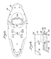
- Figure 8 is a bottom plan view of the snowdeck shown in Figures 5-7;
- Figure 9 is an exploded view showing traction cleats which would be mounted to the sole of the overboot and showing the components of the locking mechanism incorporated in the snowdeck in the system of Figure 1;
- Figure 10 is an exploded view showing components of the locking mechanism shown in Figure 9;
- Figure 11 is a fragmental exploded view showing components of the locking mechanism and the overboot cleats in an initial stage of mounting;
- Figure 12 is a top plan view of various components of the locking assembly shown in Figures 9-10 in the disengaged condition;
- Figure 13 is an elevational view in section showing the traction cleat of the overboot in the disengaged condition;
- Figure 14 is a view similar to Figure 12 showing the components in the engaged position; and
- Figure 15 is a view similar to Figure 13 showing the components in the engaged position.
- The present invention is directed to providing a modular snow travel system for common footwear. In one practice of the invention a first flexible or inflexible traction component is provided which is adapted to be attached to conventional footwear such as running shoes or other types of footwear or to the foot itself. The first traction component could be an overboot which will be described with greater particularity or could simply be some form of binding assembly that could be attached to the footwear or the foot and fulfill all the other basic functions required of the first traction component and would be secured only in part over the footwear or foot.
- The first traction component has at least one traction cleat attached thereto, preferably in the forefoot region, so as to provide improved traction when walking or running on ice, snow or other slippery surfaces. For use in deep snow or where greater stability is required, a snowdeck is also provided that includes a locking mechanism adapted to secure to at least one of the cleats of the first traction component and attach it to the snowdeck. Preferably the attachment to the snowdeck allows for the first traction component to pivot relative to the snowdeck to allow for ease in walking or running.
- Also preferably, the snowdeck includes additional traction cleats or claws attached thereto.
- The present invention provides a number of improved first traction components that are adapted to attach to a wide variety of conventional footwear styles, including boots, shoes, and running shoes or to the foot. Preferably the first traction components include one or more buckle systems to allow for quick attachment to and removal from the foot/footwear. These various forms of first traction components provide greatly improved traction for the wearer while also providing additional benefits, such as with the overboot embodiments that provide improved insulation and protection from snow, dirt, or water infiltration of the footwear. Traction cleats may be provided on the forefoot, rear-foot, or mid-foot of the first traction component, or any combination thereof.
- The various embodiments of the snowdecks allow for easy step-in addition of additional floatation and/or greater stability for the wearer. Preferably at least one of the traction cleats of the first traction component is adapted to "click in" to a binding or locking mechanism on the snowdeck. When the deck is no longer required, the locking mechanism allows for quick disengaging of the first traction component. Alternatively, utilizing the quick attachment systems on the first traction components, the wearer can leave the first traction component attached to the snowdeck and convert between conventional footwear and something akin to a conventional snowshoe configuration. Various snowdeck configurations and binding systems may be used within the scope of the present invention.
- The following description will be directed to a preferred form of modular snow travel system.
Such system 10 is illustrated in Figure 1. As shown therein a first traction component, which in Figure 1 is in the form of anoverboot 12, is detachably mounted to asnowdeck 14. - Figures 2-4 illustrate the
overboot 12 in greater detail. As shown thereinoverboot 12 can include structure to facilitate a wearer readily inserting the wearer's foot into theoverboot 12. This can be done by slipping the foot and any footwear into the opening 16 at the top of theoverboot 12.Opening 16 can be increased in size by providing, for example, azipper 18 having aslider 20 on the back ofoverboot 12. In addition, the front of the footwear could include aflap 22 that could be opened and then later closed and held in the closed condition through any suitable fastening arrangement such as illustrated bystrap structure 24 and fastener structure, such asratchet 26. It is to be understood that these forms of enlarging the opening 16 may vary in any conventional manner. Preferably, thefront opening 16 may be additionally secured through use of supplemental closure devices, such as hook-and-loop fasteners, latches, laces, zippers, or the like, that can both aid in more securely holding theoverboot 12 to the wearer and to assist in reducing snow, dirt or water infiltration into theoverboot 12. - As best shown in Figures 1-2 and 4 an advantageous feature of
overboot 12 is the inclusion of aloop 23 on each side of the overboot which slides through astrap loop 25 allowing for the precise placement of thestrap structure 24 to be adjusted up or down the boot to accommodate laces hot spots. As best shown in Figure 4 thestrap structure 24 also includes a series oftransverse teeth 27 which cooperate withratchet 26 for providing the adjustability of theopening 16 ofoverboot 12. - The lower surface of the sole 28 of
overboot 12 includes sets of cleats located at any suitable location in order to provide the desired traction to secure footing on a slippery surface. Such sets of cleats are preferably around the periphery of the sole 28 and could includecleats 30 as illustrated located at the toe and heel portions of sole 28. Additional sets ofcleats overboot 12 are mirror images of those on the other longitudinal side. - As best shown in Figure 2 a distinctive feature of
traction cleats 36 is that each traction cleat includes a latch in the form of a cutout forming an exposedhook portion 38 facing toward the toe, for purposes later described. Other forms of latch structure could also be used instead of an exposed hook portion. Examples of such latch structure include various shaped cutouts or holes or any other form of opening which would be engaged by a catch on the snowdeck, as later described. The latch could also be an exposed protrusion on thecleat 36 for engagement with a catch on the snowdeck. - As illustrated in Figure 4
overboot 12 could be lined with anysuitable insulation material 27 to provide insulation and protection from snow, dirt or water infiltration of the footwear. The overboot itself would be made of materials conventionally used in snow conditions. Preferably,overboot 12 is made of neoprene. Additionally, the sole of the overboot is preferably textured as illustrated in provisional application Serial No.60/758,890 - It is to be understood that although the drawings illustrate one overboot and one snowdeck, a complete system would, of course, be provided for each foot of the user.
- Figures 5-8 illustrate details of the
snowdeck 14. As shown therein snowdeck 14 comprises aframe 40 which may be made of any suitable material such as a metal material conventionally used for snowdecks.Frame 40 has a generally flat portion which receives the overboot and may be inclined upwardly forwardly of where the user's foot (overboot) would be located. Anysuitable decking material 42 spans the frame leaving openings as necessary or desired. As shown in Figure 8 various sets of cleats orclaws 44 are provided on the bottom of thedecking 42 to further enhance traction for use on slippery surfaces and in deep snow. Theclaws 44 may be provided at any suitable locations and may be secured to webbing 42 in any suitable manner. Preferably the claws on one longitudinal side of thesnowdeck 14 are mirror images of those on the other side. - A
heel block 46 is mounted to a heel pad orsupport 48 provided ondecking 42.Heel block 46 would be located between the sets ofclaws 44 located in the heel portion and would be of sufficient height to be surrounded by and generally elevate theoverboot cleats decking 42 so as to not damage the decking when the overboot is mounted to the snowdeck by minimizing any digging of the cleats into the decking. The spacer aspect of the heel block may maintain the cleats generally out of contact but could permit some contact as long as damage to the decking is minimized. If desired,heel block 42 could include some form of catch, such as pins which may be selectively extended from the heel block, for engagement by thehook portion 38 of thecleats 34. Where, instead of a "snowdeck", the first traction component (e.g. overboot 12) is mounted to a ski, mounting to both the forefoot and rear foot may be desired. Accordingly, the term "snowdeck" is not intended to be limited to conventional snowdecks but could include various types of devices for attachment to the feet to assist movement in snow, such as snowshoes, skis or the like. For most uses ofsystem 10, it is preferred that there be no physical attachment of the heel portion of the overboot with the snowdeck so that the user may readily pivot the user's foot by having attachment solely in the forefoot area as later described. -
Heel block 46 may be mounted on theheel area decking 42 by being secured to the heel pad orsupport member 48 which contains alongitudinal slot 50 and two sets oftransverse slots heel block 46 to be varied for accommodating different size overboots. Thus, for example,heel block 46 could include engaging members detachably mounted in the front set ofslots 52 to lock it in place orheel block 46 could be moved rearwardly inslot 50 and then engaged inrearward slots 52 where a larger size overboot is used. - The provision of a spacer such as
heel block 46 to generally elevate the cleats of the traction component from thesnowdeck 14 is a distinct advantage over prior arrangements. In that regard, a spacer assures that the cleats of a traction system in the heel area are prevented from generally contacting the snowshoe deck. Such spacer in the preferred form is a heel block, such asheel block 46 mounted directly to thesnowdeck 14. The concept of a spacer, however, may also be practiced where, for example, the spacer is mounted (such as being detachably mounted) to the traction device or traction component so that it provides a spacing member of sufficient thickness to generally elevate the cleats from the snowshoe deck. The provision of such a spacer is advantageous over prior arrangements using, for example, cutouts in the snowshoe deck to avoid contact by the cleats of the traction system. - A key feature of this invention is the provision of a
releasable locking mechanism 56 for selectively engaging the first traction component, such asoverboot 12, with thesnowdeck 14. The components of thereleasable locking mechanism 56 are best shown in Figures 9-10 and its manner of operation is best illustrated in Figures 11-15. - As shown in Figure 9 the
traction cleats 36 ofoverboot 12 cooperate with thelocking mechanism 56. The invention may be practiced where eachcleat overboot 12 by, for example, being embedded in an elastomeric mounting member which in turn is secured to the bottom of sole 28. Alternatively,cleats toe cleats plate 54 which would be incorporated in the sole 28 ofoverboot 12, such as illustrated in provisional application Serial No.60/758,890 cleats 36, are simply part of a binding that would be secured to conventional footwear and need not necessarily be part of an overboot. - Figure 9 also illustrates the components of the
releasable locking mechanism 56 that are incorporated in thesnowdeck 14. These components include aplate 58 made of any suitable material such as metal which could have downwardly extending projections that form theclaws 44.Plate 58 includes a pair ofelongated slots 60 of a size and location to receive thecleats 3G,36. - Under certain snow conditions it may be desirable to provide a
gasket 62 mounted beneath theplate 58 which covershousing 64 in order to reduce snow or other contaminants infiltrating the locking mechanism.Gasket 62 is also provided with a pair ofelongated slits 66 aligned withslots 60 ofplate 58 so that thecleats 36 also extend throughgasket 62. Theslits 66 create a seal belowslots 60 to minimize snow entering and contaminating the click-in locking mechanism. - Various components of the
locking mechanism 56 located inhousing 64 are illustrated in Figure 10. As shown in Figure 10housing 64 includes a longitudinallymovable slider 68 and a transverselymovable slider 70 which fit in an appropriately shapedrecess 72 ofhousing 64.Longitudinal slider 68 includes a groove 76 which receives afastening rod 78 the ends of which would abut againstwalls housing 64. A pair ofsprings housing 80.Longitudinal slider 68 has a pair oflegs appropriate recesses housing 64 whenslider 68 is mounted inhousing 64.Springs wall 88 oflongitudinal slider 68 to urgeslider 68 in a longitudinal direction toward the opposite end ofhousing 64.Longitudinal slider 88 has a cam wall which includes a pair of projectingsurfaces 90 and anintermediate recess 92. - As also shown in Figure 10
transverse slider 70 has a complementary cam wall which includesprojections intermediate recess 96. Theprojections slider slider 70 preferably terminate in flat portions. A release/actuation member, such as apull cord 98, is also provided intransverse slider 70.Pull cord 98 is fixedly mounted to sleeve 100 located in a notched portion ofslider 70. Thus, when the pull cord is pulled to the right or to the left theslider 70 would also be shifted laterally to the right or to the left. As shown in Figures 6,12 and 14 one end ofpull cord 98 may have ahandle 102 attached to that end, while the other end may have ahandle 104. The handles may take any suitable form such ashandle 102 being in the form of a block having grooves or ridges to facilitate gripping or could be a loop such as illustrated forhandle 104. - Preferably the pull cord is made of a strong, yet bendable material such as a braided metal wire. Other suitable materials could be used and, although not as preferred, the pull cord itself could be a stiff non-bendable member since the main requirement is that it have sufficient strength to be pulled in a transverse direction and that it is coupled to the transverse slider so that the lateral pulling is transmitted to the transverse slider to cause the transverse slider to shift back and forth to and from its locking and unlocking conditions.
- Figures 11-13 illustrate the condition of the locking mechanism when in the disengaged or the about to be engaged position. As shown therein handle or
loop 104 has been pulled to moveslider 70 toward the left. When in this position the cam faces ofslider 70 press againstlongitudinal slider 68 to force thelongitudinal slider 68 rearwardly with thesprings 82 in a compressed condition. While in this positiontransverse slider 70 is disposed againstwall 106 inrecess 72 ofhousing 64 and is stopped in this position. The flat portions at the end of theprojections 90 oflongitudinal slider 68 andprojections 94 oftransverse slider 70 abut against each other to maintainlongitudinal slider 68 in the retracted condition, best shown in Figure 12. When in this position thefastening rod 78 is moved to its retracted or disengaged position out of the path of movement ofcleats 36 when they enter thehousing 64 through theslots plate 58 andgasket 62. Figure 11 shows thecleat 36 before it enters theslot 60. Figure 13 shows howcleat 36 is able to freely pass into thehousing 64 without interference from retractedfastening rod 78. In this manner, the wearer simply places thecleats plate 58 of thesnowdeck 14 at the location of theslots cleats locking mechanism 56. - After
cleats 36 have been fully inserted into the housing 64 (Figure 13), the wearer pulls handle 102 which causestransverse slider 70 to shift in the opposite direction from that shown in Figure 12 to the position shown in Figure 14. When in this position the side wall ofslider 70 comes into contact withwall 108 ofhousing 64 and is stopped in this position. When moved to the position shown in Figure 14 the projection cam surfaces 94,94 oftransverse slider 70 no longer contact the projection cam surfaces 90,90 oflongitudinal slider 68. Instead therecess 96 oftransverse slider 70 is located at theright cam projection 90 oflongitudinal slider 68 with the other or leftcam projection 90 being against the complementary shaped inclined wall of the cam face oftransverse slider 70 as illustrated in Figure 14.Longitudinal slider 68 occupies this position by being urged outwardly under the influence ofsprings longitudinal slider 68 also carriesfastening rod 78 forwardly with it wherebyfastening rod 78 enters the exposed hook shapedportions cleats locking mechanism 56. When in this lockedcondition overboot 12 is securely mounted tosnowdeck 14 in the location of the traction cleats 36,36. As previously indicated in the preferred practice of this invention this is the only area whereoverboot 12 is locked to snowdeck 14 so that the wearer is thereby able to pivot the overboot in, for example, the heel area. The dimensions oftraction cleats 36 with regard to thelocking mechanism 56 and particularly the thickness ofhousing 64 is such that thecleats webbing 42. In that regard,cleats locking mechanism 56, whilecleats mechanism 56 is thicker than the length of these cleats, the cleats are thereby spaced fromwebbing 42. - When it is desired to remove
overboot 12 fromsnowdeck 14handle 104 is pulled to shifttransverse slider 70 back to the position shown in Figure 12 which results in returninglongitudinal slider 68 to its retracted position so that fasteningrod 78 is removed fromhook portion 38 andcleats 36 can then be removed from thelocking mechanism 56 by the wearer simply raising the foot away from thesnowdeck 14. Alternatively, thelocking mechanism 56 could remain in the locking condition and the wearer could simply remove the foot from the overboot so that theoverboot 12 remains mounted to snowdeck 14 during periods of non-use. Thus the assembly which comprises theoverboot 10 and thesnowdeck 14 could be stored together as a single unit or could be separated from each other as previously described. - Although the above description and the drawings include the provision of an exposed
hook 38 in thecleat 36 which is engaged by the locking mechanism, other forms of latch members may be used. For example, instead of an exposed hook, the latch member could be a hole or cutout in the cleat which would be selectively engaged by the movement of a bar functioning as the catch member in the locking mechanism. Such bar could be a bar of circular cross-section fitting in a circular or round hole or cutout. Alternatively, the latch might be a protrusion on thecleat 36 which would be engaged with a catch movable into the path of movement of the protrusion when thetraction cleat 36 has entered the locking mechanism. The locking mechanism itself could take any suitable form such as being part of a strap system which would have a catch member movable into the path of movement of the latch. - It is to be understood that where reference is made to a releasable locking mechanism, such locking mechanism could be of the type specifically illustrated and described or could be a strap system incorporating the components to effect the selective engagement and disengagement with the cleat of the traction component.
- An advantageous feature of this invention is that an audible click is heard when the transverse slider is moved to its locking condition and is moved to its unlocking condition. This provides assurance to the wearer that the overboot has been appropriately locked to or released from the snowdeck.
- The present system provides an advantageous manner of mounting the traction component to the snowshoe deck. When, for example, the
cleat 36 is mated with the locking mechanism and in particular with theplate 58 by entering itsslot 60, thecleat 36 is held strongly from rotating in nearly all planes even without the bar orrod 78 being clicked into place. This "nesting" of the two components assures a very secure connection and allows thecleat 36 to be removed by moving it in the vertical direction in a single plane perpendicular to the slot. Thus, while the click-in bar is important, there is still much stability built into the design even without the bar. - The preferred practice of this invention utilizes a set of two
traction cleats such traction cleats 36 with appropriate modification of the locking mechanism. - It is to be understood that the above description with regard to the illustrated preferred embodiment of this invention is not intended to be limiting and that the invention could be practiced with different variations. Reference is made to provisional application Serial No.
60/758,890, filed January 12, 2006 cleats 36 described with regard to the overboot, could be part of a separate binding where the invention is practiced without an overboot. Other variations described in the provisional application include the use of a cradle which could be inserted within an overshoe, which would be another alternative to the use of the overboot described and illustrated in Figures 2-4.
Claims (34)
- An improved traction system comprising a first traction component, said first traction component having fastening structure for attachment to foot/footwear, said first traction component having at least one traction cleat, a snowdeck, and said snowdeck having a releasable locking mechanism for selective engagement with said at least one cleat for selectively mounting said first traction component to said snowdeck and for selectively disengaging said first traction component from said snowdeck.
- The system of claim 1 wherein said at least one traction cleat includes a latch, said releasable locking mechanism including a catch movable into the path of movement of said latch when said traction cleat has entered said locking mechanism for being received in said exposed hook portion when said locking mechanism is in its locking condition and for being disposed out of contact with said latch when said locking mechanism is in its disengaging position, and said locking mechanism including an activating member for selectively moving said catch to and from said locking condition and said disengaging position.
- The system of claim 2 wherein said latch is an exposed cut-out in said traction cleat.
- The system of claim 2 wherein said catch comprises a fastening rod mounted to a longitudinal slider capable of sliding back and forth in a longitudinal direction, said longitudinal slider having a cam face, said activating member comprising a release/actuation member mounted on a transverse slider which is slidably movable in a lateral direction, said transverse slider having a cam face disposed against said cam face of said longitudinal slider, and the lateral shifting of said transverse slider controlling the longitudinal movement of said longitudinal slider to selectively dispose said fastening rod into and out of engagement with said latch of said traction cleat.
- The system of claim 4 wherein said release/actuation member is a pull cord having an exposed handle at each end.
- The system of claim 5 wherein said locking mechanism includes a housing mounted to said snowdeck, said longitudinal slider and said transverse slider being slidably mounted in said housing, and at least one spring member urging said longitudinal slider into its locking condition.
- The system of claim 6 wherein each of said cam face on said longitudinal slider and on said transverse slider includes a pair of projections with an intermediate recess spacing said projections apart so that when the tips of said projections of said sliders abut each other said longitudinal slider is moved to said disengaging position, and when said projections are aligned with said recesses said longitudinal slider is moved to said locking condition.
- The system of claim 7 wherein said locking mechanism further includes a plate mounted over said housing, and a slot extending through said plate for permitting said at least one traction cleat to pass through said plate and enter said housing.
- The system of claim 8 wherein said at least one traction cleat comprises a set of two spaced generally parallel traction cleats, said plate having a slot for each of said traction cleats, a gasket mounted below said plate, and said gasket having a sealing slit in line with each of said plate slots.
- The system of claim 9 wherein said pull cord is mounted in a sleeve disposed in a notch in said transverse slider.
- The system of claim 10 wherein said releasable locking mechanism and said at least one traction cleat are mounted in the forefoot area of said traction component, and the wearer being free to pivot the wearer's foot at the heel when said first traction component is mounted to and engaged with said snowdeck.
- The system of claim 11 wherein said first traction component comprises an overboot, said at least one traction cleat being located at the forefoot area of said overboot, and a plurality of further sets of traction cleats being disposed around the sole portion of said overboot.
- The system of claim 12 wherein said overboot includes an insulated lining, said overboot having an opening for insertion of a wearer's foot/footwear above the heel portion of said overboot, and fastening structure for tightening said opening after the wearer's foot/footwear is inserted.
- The system of claim 12 wherein said fastening structure includes a loop mounted on each side of said overboot, strap structure slidably mounted to each of said loops for adjusting the position of said strap structure up and down said loops, and a fastener mounted to said strap structure.
- The system of claim 12 wherein said snowdeck includes a plurality of claws for providing traction, and at least some of said claws extending downwardly at spaced locations from said housing plate.
- The system of claim 15 wherein said snowdeck comprises a frame, a decking spanning portions of said frame, and at least some of said claws mounted to said decking.
- The system of claim 16 including a heel block mounted to a heel pad mounted to said decking, and said heel block being of sufficient thickness to elevate said cleats of said overboot out of contact with said decking.
- The system of claim 17 wherein said heel block is longitudinally movable to different longitudinal positions for accommodating different size overboots.
- The system of claim 18 wherein said frame is upwardly angled forwardly of said overboot.
- The system of claim 1 wherein said locking mechanism includes a plate having at least one elongated slot, and said at least one traction cleat being insertable into said slot for preventing said cleat from rotating whereby said cleat is movable into and out of said slot by movement in a plane perpendicular to said slot.
- The system of claim 1 wherein said first traction component has a heel portion, at least one further traction cleat mounted to and extending outwardly from said heel portion, said snowdeck having decking including a heel area located at said heel portion of said first traction component when said first traction component is engaged with said snowdeck, a spacer between said heel portion of said first traction component and said heel area of said decking, and said spacer being of sufficient thickness to maintain said at least one further traction cleat of said first traction component generally out of contact with said decking when said first traction component is engaged with said snowdeck.
- The system of claim 21 wherein said spacer comprises a heel block mounted to said decking.
- The system of claim 22 wherein said heel block is mounted to a heel pad which is mounted to said decking, and said heel block being selectively longitudinally movable on said heel pad to different longitudinal positions for accommodating different size first traction components.
- An improved traction system comprising a first traction component, said first traction component having fastening structure for attachment to foot/footwear, said first traction component having a heel portion, a snowdeck, locking structure for selective engagement of said first traction component with said snowdeck and for selectively disengaging said first traction component from said snowdeck, said snowdeck including a decking having a heel area, a spacer located between said heel portion of said first traction component and said heel area of said decking, and said spacer being of sufficient thickness to maintain said at least one traction cleat of said heel portion generally out of contact with said decking when said first traction component is engaged with said snowdeck.
- The system of claim 24 wherein said spacer comprises a heel block mounted to said decking.
- The system of claim 25 wherein said heel block is mounted to a heel pad which is mounted to said decking, and said heel block being selectively longitudinally movable on said heel pad to different longitudinal positions for accommodating different size first traction components.
- In an overboot for use on a slippery surface wherein said overboot includes an opening for insertion of a wearer's foot/footwear and wherein said overboot includes a sole, a plurality of cleats extending downwardly from said sole, the improvement being in that at least one set of said cleats being located in the forefront area of said sole and having a latch for selective mounting to a snowdeck.
- The system of claim 27 wherein said latch is an exposed cut-out in said traction cleat.
- The system of claim 27 wherein said overboot has an opening for insertion of a wearer's foot/footwear, a loop on each side of said opening, strap structure slidably mounted to each of said loops for adjusting the position of said strap structure up and down said loops, and fastener structure mounted to said strap structure.
- The system of claim 29 wherein said strap structure includes a plurality of spaced teeth, and said fastener structure including a ratchet selectively engaged with said teeth.
- A snowdeck for use with a first traction component, said snowdeck comprising a frame, a decking spanning parts of said frame, said frame having a heel portion and a forefoot portion, a releasable locking mechanism located at said forefoot portion, said releasable locking mechanism comprising a housing, a longitudinal slider in said housing, a transverse slider in said housing, said longitudinal slider being mounted for longitudinal sliding movement, said transverse slider being mounted for lateral sliding movement, each of said sliders having a cam face, each of said cam faces having at least one projection and an adjacent recess, said transverse slider being laterally slidable to dispose its at least one projection against said at least one projection of said longitudinal slider to longitudinally move said longitudinal slider rearwardly to a disengaging position, said transverse slider being laterally movable to a position where said projections of said cam faces are out of contact with each other to permit said longitudinal slider to move longitudinally forwardly in an engaging direction, said longitudinal slider carrying a fastening rod, and said transverse slider having a release/actuation member for controlling the lateral sliding movement of said transverse slider.
- The snowdeck of claim 31 including a plate mounted over said housing, said plate having a pair of spaced generally parallel slots for receiving cleats of a traction component which is to be detachably mounted to said snowdeck, a gasket mounted below said plate, said gasket having a sealing slit below and in alignment with each of said slots, said release/actuation member comprising a pull cord mounted in a sleeve connected to said transverse slider, and a handle at each end of said pull cord.
- The system of claim 31 wherein a heel block is mounted to and extends upwardly from said decking for maintaining cleats on the first traction component generally out of contact with said decking.
- The system of claim 31 wherein said heel block is mounted to a heel pad which is mounted to said decking, and said heel block being selectively longitudinally movable on said heel pad to different longitudinal positions for accommodating different size first traction components.
Applications Claiming Priority (1)
| Application Number | Priority Date | Filing Date | Title |
|---|---|---|---|
| US75889006P | 2006-01-12 | 2006-01-12 |
Publications (2)
| Publication Number | Publication Date |
|---|---|
| EP1808088A1 true EP1808088A1 (en) | 2007-07-18 |
| EP1808088B1 EP1808088B1 (en) | 2009-07-15 |
Family
ID=37744588
Family Applications (1)
| Application Number | Title | Priority Date | Filing Date |
|---|---|---|---|
| EP07000618A Not-in-force EP1808088B1 (en) | 2006-01-12 | 2007-01-12 | Modular snow travel system for common footwear |
Country Status (3)
| Country | Link |
|---|---|
| US (2) | US7707749B2 (en) |
| EP (1) | EP1808088B1 (en) |
| DE (1) | DE602007001537D1 (en) |
Cited By (4)
| Publication number | Priority date | Publication date | Assignee | Title |
|---|---|---|---|---|
| WO2010026078A3 (en) * | 2008-08-25 | 2010-10-07 | Clarissa Kessler | Snow shoe comprising an intermediate element and a coupling device |
| EP2647304A1 (en) * | 2012-04-06 | 2013-10-09 | Salomon S.A.S. | Footwear element |
| FR3031884A1 (en) * | 2015-01-27 | 2016-07-29 | Salomon Sas | FOOTWEAR ELEMENT |
| EP3108944A1 (en) | 2015-06-22 | 2016-12-28 | Salomon S.A.S. | Tread item intended for being mounted on a vehicle and device comprising such a tread element and a vehicle |
Families Citing this family (6)
| Publication number | Priority date | Publication date | Assignee | Title |
|---|---|---|---|---|
| US7707749B2 (en) * | 2006-01-12 | 2010-05-04 | Kahtoola, Inc. | Modular snow travel system for common footwear |
| US8061062B2 (en) * | 2006-01-12 | 2011-11-22 | Kahtoola Inc. | Modular snow travel system for common footwear |
| FR3007949B1 (en) * | 2013-07-04 | 2015-12-11 | Salomon Sas | SHOE FOR SHOE |
| US10314367B2 (en) * | 2014-02-07 | 2019-06-11 | Nike, Inc. | Sole structure for an article of footwear with extended plate |
| JP7652701B2 (en) | 2018-10-18 | 2025-03-27 | ヒルサウンド イクィップメント インコーポレイテッド | Crampons with recessed cleats |
| USD928490S1 (en) | 2018-10-18 | 2021-08-24 | Hillsound Equipment Inc. | Crampon |
Citations (4)
| Publication number | Priority date | Publication date | Assignee | Title |
|---|---|---|---|---|
| US4620375A (en) * | 1984-07-02 | 1986-11-04 | Wallace Robert E | Snowshoe binding and ice crampon or the like |
| DE19918871A1 (en) * | 1999-04-26 | 2000-11-02 | Moritz Mueller | Snow boot with frame and mesh support face includes crampon detachably connectable to boot and with openings in support face for claws of crampon |
| US20010039749A1 (en) * | 1998-01-21 | 2001-11-15 | Warner Charles Bently | Terrain-engaging cleat for traction enhancement |
| US20040148802A1 (en) * | 2003-01-23 | 2004-08-05 | Soriano Antonio Cutando | Perfected device for walking on snow or ice |
Family Cites Families (4)
| Publication number | Priority date | Publication date | Assignee | Title |
|---|---|---|---|---|
| US5901471A (en) * | 1998-01-21 | 1999-05-11 | Atlas Snowshoe Company | Snowshoe for receiving crampons |
| US6265037B1 (en) * | 1999-04-16 | 2001-07-24 | Andersen Corporation | Polyolefin wood fiber composite |
| US6684534B2 (en) * | 2001-09-28 | 2004-02-03 | K2 Snowshoes, Inc. | Step-in snowshoe binding system |
| US7707749B2 (en) * | 2006-01-12 | 2010-05-04 | Kahtoola, Inc. | Modular snow travel system for common footwear |
-
2007
- 2007-01-11 US US11/622,038 patent/US7707749B2/en active Active
- 2007-01-12 EP EP07000618A patent/EP1808088B1/en not_active Not-in-force
- 2007-01-12 DE DE602007001537T patent/DE602007001537D1/en active Active
-
2010
- 2010-04-14 US US12/759,938 patent/US20100192417A1/en not_active Abandoned
Patent Citations (4)
| Publication number | Priority date | Publication date | Assignee | Title |
|---|---|---|---|---|
| US4620375A (en) * | 1984-07-02 | 1986-11-04 | Wallace Robert E | Snowshoe binding and ice crampon or the like |
| US20010039749A1 (en) * | 1998-01-21 | 2001-11-15 | Warner Charles Bently | Terrain-engaging cleat for traction enhancement |
| DE19918871A1 (en) * | 1999-04-26 | 2000-11-02 | Moritz Mueller | Snow boot with frame and mesh support face includes crampon detachably connectable to boot and with openings in support face for claws of crampon |
| US20040148802A1 (en) * | 2003-01-23 | 2004-08-05 | Soriano Antonio Cutando | Perfected device for walking on snow or ice |
Cited By (9)
| Publication number | Priority date | Publication date | Assignee | Title |
|---|---|---|---|---|
| WO2010026078A3 (en) * | 2008-08-25 | 2010-10-07 | Clarissa Kessler | Snow shoe comprising an intermediate element and a coupling device |
| EP2647304A1 (en) * | 2012-04-06 | 2013-10-09 | Salomon S.A.S. | Footwear element |
| FR2988981A1 (en) * | 2012-04-06 | 2013-10-11 | Salomon Sas | FOOTWEAR ELEMENT |
| CN103416898A (en) * | 2012-04-06 | 2013-12-04 | 萨洛蒙股份有限公司 | Footwear element |
| US9936768B2 (en) | 2012-04-06 | 2018-04-10 | Salomon S.A.S. | Footwear element |
| FR3031884A1 (en) * | 2015-01-27 | 2016-07-29 | Salomon Sas | FOOTWEAR ELEMENT |
| EP3050451A1 (en) * | 2015-01-27 | 2016-08-03 | Salomon S.A.S. | Footwear element |
| US9936769B2 (en) | 2015-01-27 | 2018-04-10 | Salomon S.A.S. | Footwear element |
| EP3108944A1 (en) | 2015-06-22 | 2016-12-28 | Salomon S.A.S. | Tread item intended for being mounted on a vehicle and device comprising such a tread element and a vehicle |
Also Published As
| Publication number | Publication date |
|---|---|
| US20100192417A1 (en) | 2010-08-05 |
| EP1808088B1 (en) | 2009-07-15 |
| US7707749B2 (en) | 2010-05-04 |
| US20080010865A1 (en) | 2008-01-17 |
| DE602007001537D1 (en) | 2009-08-27 |
Similar Documents
| Publication | Publication Date | Title |
|---|---|---|
| EP1808088B1 (en) | Modular snow travel system for common footwear | |
| US8763210B2 (en) | Locking device for a buckle | |
| JP3529754B2 (en) | Shoes that are easy to wear | |
| US9242168B1 (en) | Snowboard binding and boot | |
| US10702762B2 (en) | Snowboard binding and boot | |
| US7716855B2 (en) | Mounting for retaining a boot on a snowshoe | |
| US20070000105A1 (en) | Lace locking device | |
| EP1149609A1 (en) | Tool free system for adjusting the mounting location of an engagement member | |
| CN101018492A (en) | Sandal with interchangeable upper | |
| WO1996036406A1 (en) | Snowboard bindings with release apparatus | |
| US6557866B2 (en) | Snowboard binding | |
| US20030052473A1 (en) | Cleated overshoe and snowshoe with binding for accepting same | |
| JP2004533291A (en) | Binding system | |
| US8061062B2 (en) | Modular snow travel system for common footwear | |
| US6105993A (en) | Interface for connecting a boot and a gliding board | |
| WO1999002228A1 (en) | Device for detachable fastening of boots to a frame of roller skates, ice skates, snow boards, or similar equipment | |
| US9220970B1 (en) | Snowboard binding and boot | |
| WO1996003186A1 (en) | Snowboot with attachment pins | |
| US20050079777A1 (en) | Flipper | |
| EP1360910B1 (en) | Easy-to-wear footwear | |
| KR200338963Y1 (en) | Zipper slide | |
| WO2021068166A1 (en) | Boot suitable for skiing and general use | |
| CA2978230C (en) | Ski boot device | |
| CA2388257A1 (en) | Easy-to-wear footwear | |
| CA2592980A1 (en) | Snowshoe accessory |
Legal Events
| Date | Code | Title | Description |
|---|---|---|---|
| PUAI | Public reference made under article 153(3) epc to a published international application that has entered the european phase |
Free format text: ORIGINAL CODE: 0009012 |
|
| AK | Designated contracting states |
Kind code of ref document: A1 Designated state(s): AT BE BG CH CY CZ DE DK EE ES FI FR GB GR HU IE IS IT LI LT LU LV MC NL PL PT RO SE SI SK TR |
|
| AX | Request for extension of the european patent |
Extension state: AL BA HR MK YU |
|
| 17P | Request for examination filed |
Effective date: 20071206 |
|
| 17Q | First examination report despatched |
Effective date: 20080121 |
|
| AKX | Designation fees paid |
Designated state(s): DE FR GB IT SE |
|
| GRAP | Despatch of communication of intention to grant a patent |
Free format text: ORIGINAL CODE: EPIDOSNIGR1 |
|
| GRAS | Grant fee paid |
Free format text: ORIGINAL CODE: EPIDOSNIGR3 |
|
| GRAA | (expected) grant |
Free format text: ORIGINAL CODE: 0009210 |
|
| AK | Designated contracting states |
Kind code of ref document: B1 Designated state(s): DE FR GB IT SE |
|
| REG | Reference to a national code |
Ref country code: GB Ref legal event code: FG4D |
|
| REF | Corresponds to: |
Ref document number: 602007001537 Country of ref document: DE Date of ref document: 20090827 Kind code of ref document: P |
|
| REG | Reference to a national code |
Ref country code: SE Ref legal event code: TRGR |
|
| PLBE | No opposition filed within time limit |
Free format text: ORIGINAL CODE: 0009261 |
|
| STAA | Information on the status of an ep patent application or granted ep patent |
Free format text: STATUS: NO OPPOSITION FILED WITHIN TIME LIMIT |
|
| 26N | No opposition filed |
Effective date: 20100416 |
|
| PGRI | Patent reinstated in contracting state [announced from national office to epo] |
Ref country code: IT Effective date: 20110501 |
|
| REG | Reference to a national code |
Ref country code: FR Ref legal event code: PLFP Year of fee payment: 9 |
|
| PGFP | Annual fee paid to national office [announced via postgrant information from national office to epo] |
Ref country code: IT Payment date: 20150109 Year of fee payment: 9 |
|
| PGFP | Annual fee paid to national office [announced via postgrant information from national office to epo] |
Ref country code: GB Payment date: 20150107 Year of fee payment: 9 Ref country code: FR Payment date: 20150108 Year of fee payment: 9 |
|
| GBPC | Gb: european patent ceased through non-payment of renewal fee |
Effective date: 20160112 |
|
| REG | Reference to a national code |
Ref country code: FR Ref legal event code: ST Effective date: 20160930 |
|
| PG25 | Lapsed in a contracting state [announced via postgrant information from national office to epo] |
Ref country code: GB Free format text: LAPSE BECAUSE OF NON-PAYMENT OF DUE FEES Effective date: 20160112 |
|
| PG25 | Lapsed in a contracting state [announced via postgrant information from national office to epo] |
Ref country code: FR Free format text: LAPSE BECAUSE OF NON-PAYMENT OF DUE FEES Effective date: 20160201 |
|
| PG25 | Lapsed in a contracting state [announced via postgrant information from national office to epo] |
Ref country code: IT Free format text: LAPSE BECAUSE OF NON-PAYMENT OF DUE FEES Effective date: 20160112 |
|
| PGFP | Annual fee paid to national office [announced via postgrant information from national office to epo] |
Ref country code: DE Payment date: 20180103 Year of fee payment: 12 |
|
| PGFP | Annual fee paid to national office [announced via postgrant information from national office to epo] |
Ref country code: SE Payment date: 20180111 Year of fee payment: 12 |
|
| REG | Reference to a national code |
Ref country code: DE Ref legal event code: R119 Ref document number: 602007001537 Country of ref document: DE |
|
| PG25 | Lapsed in a contracting state [announced via postgrant information from national office to epo] |
Ref country code: SE Free format text: LAPSE BECAUSE OF NON-PAYMENT OF DUE FEES Effective date: 20190113 Ref country code: DE Free format text: LAPSE BECAUSE OF NON-PAYMENT OF DUE FEES Effective date: 20190801 |