EP1807938B1 - Method and system for processing wireless digital multimedia - Google Patents
Method and system for processing wireless digital multimedia Download PDFInfo
- Publication number
- EP1807938B1 EP1807938B1 EP05803905.8A EP05803905A EP1807938B1 EP 1807938 B1 EP1807938 B1 EP 1807938B1 EP 05803905 A EP05803905 A EP 05803905A EP 1807938 B1 EP1807938 B1 EP 1807938B1
- Authority
- EP
- European Patent Office
- Prior art keywords
- data
- bit
- video
- word
- receiver
- Prior art date
- Legal status (The legal status is an assumption and is not a legal conclusion. Google has not performed a legal analysis and makes no representation as to the accuracy of the status listed.)
- Expired - Fee Related
Links
Images


Classifications
-
- G—PHYSICS
- G09—EDUCATION; CRYPTOGRAPHY; DISPLAY; ADVERTISING; SEALS
- G09G—ARRANGEMENTS OR CIRCUITS FOR CONTROL OF INDICATING DEVICES USING STATIC MEANS TO PRESENT VARIABLE INFORMATION
- G09G5/00—Control arrangements or circuits for visual indicators common to cathode-ray tube indicators and other visual indicators
- G09G5/003—Details of a display terminal, the details relating to the control arrangement of the display terminal and to the interfaces thereto
- G09G5/006—Details of the interface to the display terminal
-
- H—ELECTRICITY
- H04—ELECTRIC COMMUNICATION TECHNIQUE
- H04L—TRANSMISSION OF DIGITAL INFORMATION, e.g. TELEGRAPHIC COMMUNICATION
- H04L12/00—Data switching networks
- H04L12/28—Data switching networks characterised by path configuration, e.g. LAN [Local Area Networks] or WAN [Wide Area Networks]
- H04L12/2803—Home automation networks
- H04L12/2805—Home Audio Video Interoperability [HAVI] networks
-
- H—ELECTRICITY
- H04—ELECTRIC COMMUNICATION TECHNIQUE
- H04L—TRANSMISSION OF DIGITAL INFORMATION, e.g. TELEGRAPHIC COMMUNICATION
- H04L65/00—Network arrangements, protocols or services for supporting real-time applications in data packet communication
- H04L65/1066—Session management
- H04L65/1101—Session protocols
-
- H—ELECTRICITY
- H04—ELECTRIC COMMUNICATION TECHNIQUE
- H04L—TRANSMISSION OF DIGITAL INFORMATION, e.g. TELEGRAPHIC COMMUNICATION
- H04L67/00—Network arrangements or protocols for supporting network services or applications
- H04L67/01—Protocols
- H04L67/12—Protocols specially adapted for proprietary or special-purpose networking environments, e.g. medical networks, sensor networks, networks in vehicles or remote metering networks
-
- H—ELECTRICITY
- H04—ELECTRIC COMMUNICATION TECHNIQUE
- H04N—PICTORIAL COMMUNICATION, e.g. TELEVISION
- H04N21/00—Selective content distribution, e.g. interactive television or video on demand [VOD]
- H04N21/40—Client devices specifically adapted for the reception of or interaction with content, e.g. set-top-box [STB]; Operations thereof
- H04N21/43—Processing of content or additional data, e.g. demultiplexing additional data from a digital video stream; Elementary client operations, e.g. monitoring of home network or synchronising decoder's clock; Client middleware
- H04N21/436—Interfacing a local distribution network, e.g. communicating with another STB or one or more peripheral devices inside the home
- H04N21/4363—Adapting the video or multiplex stream to a specific local network, e.g. a IEEE 1394 or Bluetooth® network
- H04N21/43632—Adapting the video or multiplex stream to a specific local network, e.g. a IEEE 1394 or Bluetooth® network involving a wired protocol, e.g. IEEE 1394
- H04N21/43635—HDMI
-
- H—ELECTRICITY
- H04—ELECTRIC COMMUNICATION TECHNIQUE
- H04N—PICTORIAL COMMUNICATION, e.g. TELEVISION
- H04N21/00—Selective content distribution, e.g. interactive television or video on demand [VOD]
- H04N21/40—Client devices specifically adapted for the reception of or interaction with content, e.g. set-top-box [STB]; Operations thereof
- H04N21/43—Processing of content or additional data, e.g. demultiplexing additional data from a digital video stream; Elementary client operations, e.g. monitoring of home network or synchronising decoder's clock; Client middleware
- H04N21/436—Interfacing a local distribution network, e.g. communicating with another STB or one or more peripheral devices inside the home
- H04N21/4363—Adapting the video or multiplex stream to a specific local network, e.g. a IEEE 1394 or Bluetooth® network
- H04N21/43637—Adapting the video or multiplex stream to a specific local network, e.g. a IEEE 1394 or Bluetooth® network involving a wireless protocol, e.g. Bluetooth, RF or wireless LAN [IEEE 802.11]
-
- G—PHYSICS
- G09—EDUCATION; CRYPTOGRAPHY; DISPLAY; ADVERTISING; SEALS
- G09G—ARRANGEMENTS OR CIRCUITS FOR CONTROL OF INDICATING DEVICES USING STATIC MEANS TO PRESENT VARIABLE INFORMATION
- G09G2370/00—Aspects of data communication
- G09G2370/04—Exchange of auxiliary data, i.e. other than image data, between monitor and graphics controller
- G09G2370/045—Exchange of auxiliary data, i.e. other than image data, between monitor and graphics controller using multiple communication channels, e.g. parallel and serial
- G09G2370/047—Exchange of auxiliary data, i.e. other than image data, between monitor and graphics controller using multiple communication channels, e.g. parallel and serial using display data channel standard [DDC] communication
-
- G—PHYSICS
- G09—EDUCATION; CRYPTOGRAPHY; DISPLAY; ADVERTISING; SEALS
- G09G—ARRANGEMENTS OR CIRCUITS FOR CONTROL OF INDICATING DEVICES USING STATIC MEANS TO PRESENT VARIABLE INFORMATION
- G09G2370/00—Aspects of data communication
- G09G2370/10—Use of a protocol of communication by packets in interfaces along the display data pipeline
-
- G—PHYSICS
- G09—EDUCATION; CRYPTOGRAPHY; DISPLAY; ADVERTISING; SEALS
- G09G—ARRANGEMENTS OR CIRCUITS FOR CONTROL OF INDICATING DEVICES USING STATIC MEANS TO PRESENT VARIABLE INFORMATION
- G09G2370/00—Aspects of data communication
- G09G2370/12—Use of DVI or HDMI protocol in interfaces along the display data pipeline
-
- G—PHYSICS
- G09—EDUCATION; CRYPTOGRAPHY; DISPLAY; ADVERTISING; SEALS
- G09G—ARRANGEMENTS OR CIRCUITS FOR CONTROL OF INDICATING DEVICES USING STATIC MEANS TO PRESENT VARIABLE INFORMATION
- G09G2370/00—Aspects of data communication
- G09G2370/16—Use of wireless transmission of display information
Definitions
- the present invention relates generally to wireless multimedia presentation systems.
- Digital video can be transmitted from a source, such as a DVD player, video receiver, ATSC tuner, or other computer, to a display, such as a flat panel video monitor, using a protocol known as Digital Visual Interface (DVI).
- DVI Digital Visual Interface
- HDMI High Definition Multimedia Interface
- DVI Digital Content Protection
- HDCP High-Bandwidth Digital Content Protection
- the present invention further understands, however, that not just any wireless transmission system will do. Specifically, if a wireless link such as IEEE 802.11(b) is used that has a bandwidth which is insufficient to carry either compressed or uncompressed multimedia such as uncompressed high definition (HD) video, compressed multimedia standard definition (SD) video would have to be transmitted, requiring a relatively expensive decompression module at the projector. Some links such as IEEE 802.11 (a) do have a bandwidth high enough to carry compressed HD video but not uncompressed SD or HD video. Also, in the case of 802.11 (a) copyright protection may be implicated because the link is sufficiently long range (extending beyond the room in which it originates) that it can be detected beyond the immediate location of the transmitting laptop. With this in mind, the present invention recognizes the need for a very short range, preferably directional, high bandwidth wireless link that is particularly suited for the short range wireless communication of uncompressed multimedia, particularly the rather voluminous genre of multimedia known as HD video.
- a wireless link such as IEEE 802.11
- the present assignee has provided a wireless system that functions in the spectrum between 57GHz and 64GHz (hereinafter "60GHz band"). Characteristics of the 60GHz spectrum include short range, high directivity (and, hence, inherent security), and large data bandwidth.
- the present assignee's co-pending U.S. patent applications serial nos. 10/666,724 , 10/744,903 (also WO 2005/067458 ) (systems), 10/893,819, 11/136,199 (PLL-related inventions), and 11/035,845 (multiple antennae) disclose various systems and methods for sending high definition (HD) video in High Definition Multimedia Interface (HDMI) format from a source in a room to a receiver in the room, using a high bandwidth 60GHz link.
- HDMI High Definition Multimedia Interface
- WO 2005/067458 describes WO 2005/067458 describes a system for sending multimedia data between a first HDMI component and a second HDMI component that is engaged with a displayer of multimedia data. It includes a first DVI component receiving HDCP-encrypted multimedia data from the first HDMI component over a wire. A wireless transmitter sends data from the first DVI component to a wireless receiver, preferably at 60GHz, and the receiver in turn sends the data to a second DVI component. Neither DVI component encrypts or decrypts data. The second DVI component sends the multimedia data to a second HDMI component for decryption and display.
- the present invention makes the following critical observation about 60GHz wireless links.
- simpler, non-audio DVI components are less expensive than HDMI components which add the feature of audio and, hence, would be desirable to use when feasible in lieu of HDMI components.
- an HDMI transmitter will never send HDMI data to a DVI receiver once the transmitter discovers that the receiver is not HDMI, so it can be difficult to mix the two systems. Nonetheless, the present invention understands that it is possible to selectively use less expensive DVD components in an HDMI system.
- a system for wirelessly transmitting HDMI data from a source to a display includes a DVI receiver receiving HDMI data, and a transmit digital processing system receiving an output of the DVI receiver.
- a wireless transmitter receives an output of the transmit digital processing system and wirelessly sends it to a receiver, where a receive digital processing system receives an output of the receiver and sends it to a DVI transmitter.
- a display receives the output of the DVI transmitter and displays, in response, the HDMI data, including audio data present in the HDMI data.
- a transmit digital processing system for wireless transmission of HDMI and/or DVI data.
- the system converts the data into two data streams and includes a front end component multiplexing video data with control data.
- a forward error correcting component such as, e.g., a Reed-Solomon encoder receives an output of the front end component, which outputs a substantially continuous stream of data to the Reed-Solomon Encoder. If a video data rate to the front end component is insufficient to satisfy the RS Encoder, null words are generated by the front end component such that the RS Encoder is never starved for data.
- the front end component can combine four 25-bit values to form a single 100-bit word and then convert the 100-bit word into five 20-bit words.
- a scrambler receives data from the forward error correcting component and randomizes the data.
- a header generator can be provided for periodically outputting a header, a first portion of which includes preset data useful for synchronizing a receiver and a second portion of which includes variable data including control information useful by the receiver.
- Each header is associated with a unit of multimedia data from the scrambler.
- a differential encoder can be used to represent absolute data from the header generator as phase shifted quadrature data.
- the transmit processing system is implemented by an FPGA configured for preparing the HDMI and/or DVI data for wireless transmission in the 60GHz band.
- a receive digital processing system for wireless reception of HDMI and/or DVI data deserializes received data using a deserializer which aligns data by using a first character of a received header to perform alignment in both I and Q channels.
- a system is shown, generally designated 10, which includes a source 12 of baseband multimedia data, and in particular high definition (HD) digital video with audio.
- the source 12 may be a laptop computer or other multimedia computer or server. Or, it can be a satellite, broadcast, or cable receiver, or it can be a DVD player or other multimedia source.
- the source 12 sends multiplexed multimedia data over lines 14 to a media receiver 16, so that the source 12 and media receiver 16 together may be thought of as a "source" of data and specifically of HDMI data.
- the media receiver 16 may be a set-top box that can include a High Definition Multimedia Interface (HDMI) transmitter 18.
- HDMI transmitter 18 employs HDMI protocols to process the multimedia data by, among other things, encrypting the data using High-Bandwidth Digital Content Protection (HDCP) and supporting TV resolutions such as 16 x 9 display ratios to the multimedia data.
- HDMI protocols to process the multimedia data by, among other things, encrypting the data using High-Bandwidth Digital Content Protection (HDCP) and supporting TV resolutions such as 16 x 9 display ratios to the multimedia data.
- HDMICP High-Bandwidth Digital Content Protection
- the HDMI transmitter 18 sends HDCP-encrypted multimedia data over a cable or other wire 19 to a Digital Visual Interface (DVI) receiver 20.
- DVI Digital Visual Interface
- the DVI receiver 20 uses DVI protocols to process the received data.
- the HDMI transmitter 18 multiplexes the video and multiplexes the audio within the video data stream.
- the DVI receiver 20 demultiplexes the video while passing through the audio multiplexed within the data stream. In any case, at no time need the DVI receiver 20 decrypt or re-encrypt the stream.
- the encrypted multimedia data from the DVI receiver 20 is sent to a processor 22, such as an application specific integrated circuit (ASIC) or field programmable gate array (FPGA) or other microprocessor.
- ASIC application specific integrated circuit
- FPGA field programmable gate array
- the processor 22 processes the data for wireless transmission by a wireless transmitter 24 over a transmitting antenna 26.
- the processor 22 is described further below.
- the encrypted multimedia data is wirelessly transmitted over a wireless link 30 to a receiver antenna 32, which sends the data to a wireless receiver 34.
- Multimedia may be transmitted in an uncompressed form on the link 30 such that so much data is transmitted each second that bootlegging the content is essentially untenable, although some data compression less preferably may be implemented.
- the data may also be transmitted in compressed form if desired.
- the transmitter 24 and receiver 34 (and, hence, link 30) preferably operate at a fixed (unvarying, single-only) frequency of approximately sixty GigaHertz (60GHz), and more preferably in the range of 59GHz-64GHz, and the link 30 may have a data rate, preferably fixed, of at least two Giga bits per second (2.0 Gbps). When DQPSK is used the data rate may be 2.2 Gbps, and the link may have a data rate of approximately 2.5 Gbps.
- the link may have a fixed bandwidth of two and half GigaHertz (2.5GHz).
- the wireless transmitter 24 preferably includes an encoder for encoding in accordance with principles known in the art.
- the encoded data is modulated and upconverted by an upconverter for transmission over the link 30 at about 60GHz (i.e., in the 60GHz band).
- an upconverter for transmission over the link 30 at about 60GHz (i.e., in the 60GHz band).
- a high data rate yet simple system can be achieved.
- DQPSK is used, a data rate of twice the symbol rate can be achieved.
- 8-PSK a data rate of 3.3 Gbps may be achieved.
- the wireless receiver 34 includes circuitry that is complimentary to the wireless transmitter 24, namely, a downconverter, a demodulator, and a decoder.
- the data from the wireless receiver 34 is sent to a processor 36 for error correction and re-multiplexing as appropriate for use by a DVI transmitter 38.
- the processor 36 can also demultiplex any control signals for the display from within the video data as might be necessary.
- the DVI transmitter 38 operates in accordance with DVI principles known in the art to process the encrypted multimedia without ever decrypting it, and to send the multimedia data over a cable or other wire 39 to a HDMI receiver 40 that may be part of a media player 42, such as a DVD player or TV or other player.
- the HDMI receiver 40 decrypts the multimedia data in accordance with HDCP principles and demultiplexes the audio data from the video data.
- the multimedia content may then be displayed on a display 44, such as a cathode ray tube (CRT), liquid crystal display (LCD), plasma display panel (PDP), or TFT, or projector with screen, etc.
- a display 44 such as a cathode ray tube (CRT), liquid crystal display (LCD), plasma display panel (PDP), or TFT, or projector with screen, etc.
- CTR cathode ray tube
- LCD liquid crystal display
- PDP plasma display panel
- TFT projector with screen
- the link described above is preferably bi-directional, and return channel information that is necessary for, e.g., HDCP decryption purposes may be sent on a return link in the 60GHz band or it may be sent on a return link "out of band" as disclosed in, e.g., the present assignee's co pending U.S. patent applications serial nos. 11/036,932 and 11/035,845 .
- the DVI receiver 20, processor 22, and wireless transmitter 24 may be contained on a single chip, or on separate substrates. Indeed, the DVI receiver 20, processor 22, and wireless transmitter 24 may be integrated into the media receiver 16. Likewise, the wireless receiver 34, processor 36, and DVI transmitter 38 may be implemented on a single chip and may be integrated into the media player 42 if desired. In any case, the media receiver 16 and media player 42 and respective components preferably are co-located in the same space, owing to the preferred 60GHz wireless transmission frequency, which cannot penetrate walls.
- DVI components are used in the wireless connection of the communication path between the media receiver 16 (e.g., a set-top box) and the media player 42 (e.g., a TV or DVD player), no encryption keys (or concomitant licenses) are required for this link. Also, because the multimedia is never decrypted in the wireless connection established between the DVI components 20, 38 inclusive, little or no licensing concerns are implicated. Furthermore, owing to the above-described use of DVI components, any HDMI compliant display 44 that is connected to the source 12 via the wireless link, along with the source 12, behave as though they are connected by wires, because the system is capable of accurately reproducing all HDMI output signals including a frequency-accurate copy of the video clock. Specifically, use of a DVI receiver 20 in the transmitter portion to drive the DVI transmitter 38 in the receiver portion results in the HDMI display 44 interpreting the resulting data stream correctly, including any audio data that might be delivered in so-called "data islands".
- Transmit FPGA converts 24-bit video data into two 1.1 Gbps data streams. It does this in a series of steps.
- a Front End 46 multiplexes 24-bit video data with 5-bit control data (HS, VS and Control[3:1]) and optional ancillary data.
- the Front End 46 outputs a near continuous stream of 20-bit data at, e.g., 110MHz to a Reed-Solomon (RS) Encoder 48. If the incoming video data rate is insufficient to satisfy the RS Encoder, null words are generated such that the RS Encoder is never starved for data.
- RS Reed-Solomon
- the RS Encoder 48 may include two 10-bit encoders that apply an RS code of (216, 200).
- the RS Encoders each accept two hundred 10-bit words of data and add sixteen words of forward error correction (FEC) data.
- FEC forward error correction
- This coding scheme enables the receiver to correct up to eight errors in each RS block of 216 words.
- forward error correction such as Reed-Solomon is advantageous to correct occasional transmission errors that can be present in wireless transmission systems, which if left uncorrected could temporarily disrupt the displayed image or produce video artifacts.
- Data is sent from the RS encoder 48 to a Scrambler 50, which randomizes the data.
- the Scrambler 50 is not used for any encryption purpose, which is effected by the higher-level protocol HDCP mentioned above. Instead, the Scrambler 50 randomizes the data to ensure that frequent transitions occur in the data stream, which advantageously allow the receiver to better synchronize itself to the bit clock and recover the data.
- the Scrambler 50 can use a pseudo-random number (PRN) generator to create a twenty-bit random number for each twenty-bit word, with the incoming word being exclusive-OR'ed with the random number to produce a scrambled output.
- PRN pseudo-random number
- An identical PRN generator is used in the receiver to unscramble the data, and both PRN generators may be initialized every 20uS.
- Data from the scrambler 50 is sent to a Header Generator 52 which periodically (e.g., every twenty microseconds) outputs a header of, e.g., forty words.
- the first twenty words of this header may be preset data, which is used to synchronize the receiver. This is followed by twenty words of variable data, which can include control information that may be used by the receiver.
- the Header Generator 52 can pass ten scrambled RS blocks of data (2160 words) on to a Differential Encoder 54, and then repeat the process.
- the Differential Encoder 54 accepts the twenty-bit data as a pair of ten-bit words.
- the encoder 54 evaluates each word pair as ten 2-bit entities, starting with the most significant bits.
- Each 2-bit value is compared to the previous 2-bit value.
- the difference may be represented using Gray code and output to I and Q stream Serializers 56.
- the purpose is to represent the absolute data as phase shifted quadrature data as it exits the Serializers 56 and enters the wireless transmitter 24 shown in Figure 1 , e.g., a QPSK modulator.
- the Serializers 56 may include two special purpose FPGA cells that, in one non-limiting implementation, may be Xilinx "RocketIO" cells that are ten-bit serializers which accept the differentially encoded data in parallel and shift it out a bit at a time to the I/Q outputs.
- Figure 2 also shows a Clock Generator 58, which synthesizes a clock (such as a 1.1GHz clock) used by the Serializers 56 and a, e.g., 110MHz clock for shifting the parallel data though the system.
- a clock such as a 1.1GHz clock
- 1.1GHz can be used because the RF modulator and demodulators may be tuned to operate at this specific bit rate.
- 110MHz may be used because it is exactly one-tenth of the 1.1 GHz bitrate.
- a Controller 60 is provided to synchronize all components of the non-limiting Transmit FPGA 22 shown in Figure 2 . It tells the Header Generator 52 when to generate the forty-word header and initializes the PRN generator in the Scrambler 50. The Controller 60 also starts the RS Encoder 48 such that its output will be present at the proper time, and the Controller 60 informs the Front End 46 when data must be available to the RS Encoder 48.
- the Controller 60 can use a 2200 state counter, with the 2200 states being defined by the ten 216-word RS blocks (2160 states) and forty header words.
- the Controller 60 may output a clock to a Video Clock Analyzer 62 with each pass through the 2200 state counter (i.e. every 20uS).
- the Video Clock Analyzer (VCA) 62 counts the number of video clocks during the 2200 states of the Controller 60 (20uS).
- the resulting count "n" is transmitted to the receiver as part of the header's variable data "n” that is used in the receiver to regenerate the video clock in accordance with the above-incorporated applications divulging PLL-related inventions.
- the Front End 46 of the Transmit FPGA 22 is responsible for multiplexing video data into a twenty-bit data stream.
- the primary issues associated with this task are as follows:
- the Front End 46 may be partitioned into four blocks as shown.
- Video/control data enters a Front End Multiplexer 64 at the rate of one video pixel or one control word for every video clock.
- the Multiplexer 64 outputs a 25-bit word with DE as the most significant bit.
- Ancillary data could be any additional data that may be useful at the receiver.
- ancillary data can include commands to increase/decrease display brightness.
- the Multiplexer 64 thus outputs only video pixel data and control data. Null fill data is generated in a 100-to-20 bit Converter 66. As understood herein, eventually, the 25-bit output of the Multiplexer 64 must be converted to 20-bit values. This conversion is performed in two steps. First, four 25-bit values are combined to form a single 100-bit word by the Converter 66. When four 25-bit words have been assembled into a 100-bit word, they are immediately written into a Front End FIFO 68. The FIFO 68 is capable of holding fifteen 100-bit words. The FIFO 68 notifies a 100-to-20 bit converter 70 when data is available with its DAV output. The FIFO is written synchronously with the video clock and read synchronously with the 110MHz clock.
- FIG. 4 shows a non-limiting implementation of the receive processor 36, referred to herein as a "Receive FPGA".
- the receive FPGA accepts the I and Q data streams, processes the data and outputs 24-bit video. This is done in several stages as shown in Figure 4 .
- incoming I and Q data stream are processed to recover the clock and data by a non-limiting FPGA RocketIO cell with clock/data recovery capability, denoted in the block diagram as a "deserializer" 72.
- the deserializer 72 recovers clock/data automatically to extract the original 1.1 GHz transmit clock and to divide it down to 110MHz for use in moving parallel data through the system.
- the deserializer 72 determines where one word ends and the next begins within the serial data stream. This process is referred to as alignment. The deserializer 72 uses the first character of the header to perform this alignment operation in both the I and Q channels.
- the deserializer 72 performs a "bonding" operation in which the parallel I and Q data are aligned relative to each other. If, for example, the parallel I data leads or lags the parallel Q data by one or more clocks, data is skewed and processing cannot continue. To prevent this, the deserializer 72 performs the bonding operation by looking for a specific sequence of, e.g., four words occurring in both the I and Q headers. When they occur, the deserializer performs any time shifting that might be necessary to bring the I and Q channels into relative alignment with each other.
- a Header Detector 74 searches for the twenty word header that was inserted at the transmitter as disclosed above. When the header is found, the Header Detector 74 signals a receiver controller 76 to synchronize itself with the data stream. Once synchronized, the controller 76 can synchronize the other processing blocks in the receiver FPGA. The Header Detector 74 also removes the special "n" value from the variable portion of the header and sends it to a video clock generator 77 for clock recovery in accordance with the above-incorporated applications directed to PLL inventions.
- a descrambler 78 contains a PRN generator that is initialized by the controller 76 at the proper time such that the data following the header is restored to its pre-scrambled values.
- a Reed-Solomon Decoder 80 can include two 10-bit decoders, each capable of correcting a total of up to eight erroneous words in the 216-word RS data block. As each RS data block is decoded, the number of errors encountered may be monitored by a peak error detector if desired. Every 100mS, the worst error count may be displayed on an LED bar graph and the peak error detector is reset to provide feedback to the user in adjusting the antenna for optimal operation.
- the corrected 20-bit data stream is sent to the Receiver's Back End 82 for final processing and demultiplexing.
- Figure 5 shows details of the Back End 80, which is complementary to the transmitter Front End 46 and which is responsible for taking the 20-bit data stream and extracting the original video and control data. This video and control data is then output to the DVI transmitter 38 shown in Figure 1 .
- the Back End 82 receives bursts of data in which null data must be identified and discarded, with the remaining data being demultiplexed into video and control words and with the incoming and output data using completely unrelated clocks.
- the non-limiting Back End 82 may include a Stripper 84 which receives data from the RS Decoder 80.
- the controller 76 identifies every fifth word as the first word of a five word group. In each five-word group, the first word is examined, and if it is a null word, it is discarded along with the next four by the stripper 84. In contrast, if the first word is not a null word, the five word group is assembled into a 100-bit word by the stripper 84 and written to a Back End FIFO 86.
- Data from the FIFO 86 is sent to an unpacker 88 which takes data from the Back End FIFO in 100-bit words and separates each 100-bit word into four 25-bit words. If the most significant bit is a one, the remaining 24 bits are output as video data (i.e. a pixel), but if the most significant bit is a zero, the remaining 24 bits are output as control data and ancillary data.
- the Reed-Solomon code that may be used in a non-limiting implementation is (216,200).
- the transmission channel should be characterized first and the RS code then selected to achieve a desired Bit Error Rate (BER).
- BER Bit Error Rate
- the characteristics of the transmission channel can be a function of the particular installation.
- the distance between receiver and transmitter is one variable but other variables exist. For example, multi-path distortion will affect BER and is a strong function of the environment. There are other factors that impact the decision of which RS code it best, including, for example, the amount of FPGA fabric (flip-flops) required to implement the code and the requirement for real-time operation.
- the (216,200) code could be shortened to (108,100) or even (54,50) to maintain the existing redundancy while reducing the amount of FPGA fabric required. However, as understood herein a reduction in the ability to handle burst errors can accrue with the use of shorter codes.
- the (216,200) code is capable of correcting a burst of eight word errors (80 bit errors), whereas a (54,50) code can only correct a burst of two word errors (20 bit errors).
- An alternative approach to the handling of burst errors is the use of an interleaver. More specifically, an interleaver can be used to distribute burst errors over multiple RS blocks and thereby increase chances that all errors are corrected.
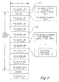
- Figure 6 shows the data stream produced by the transmitter processor 22.
- the non-limiting data format shown in Figure 6 allows video data rates up to exactly 80MHz when used at the symbol rate of 110MHz.
- 2200 20-bit symbols are sent in a series of blocks 90, with each block 90 containing its own header 92 and up to two hundred words of video/control data and if needed FEC data.
- the data frame shown in Figure 6 thus contains up to 1600 video words (pixels or controls) which, at 80MHz, represents exactly 20uS of video data.
Description
- The present invention relates generally to wireless multimedia presentation systems.
- Digital video can be transmitted from a source, such as a DVD player, video receiver, ATSC tuner, or other computer, to a display, such as a flat panel video monitor, using a protocol known as Digital Visual Interface (DVI). Having been developed primarily for computers, DVI does not envision processing audio data.
- Accordingly, to extend communication protocols to digital multimedia that includes audio for the purpose of, e.g., playing digital movies and the like, a protocol referred to as High Definition Multimedia Interface (HDMI) has been developed. HDMI is similar to DVI except it envisions the use of audio as well as video data and it adds television-related resolutions. Both DVI and HDMI are intended for wired transmission, and HDMI further permits the encryption of digital multimedia using an encryption method known as High-Bandwidth Digital Content Protection (HDCP). DVI also supports HDCP as an optional characteristic.
- As recognized herein, to save table space and to increase people's mobility and viewing lines in the room, it may be desirable to view the multimedia on a display using a minimum of wiring. For instance, it may be desirable to mount a projector on the ceiling or to mount a plasma display or liquid crystal high definition (HD) television display on a wall, out of the way and capable of receiving multimedia data for display without the need for wires, since as understood herein among other things data transmission lines often do not exist in ceilings or walls.
- The present invention further understands, however, that not just any wireless transmission system will do. Specifically, if a wireless link such as IEEE 802.11(b) is used that has a bandwidth which is insufficient to carry either compressed or uncompressed multimedia such as uncompressed high definition (HD) video, compressed multimedia standard definition (SD) video would have to be transmitted, requiring a relatively expensive decompression module at the projector. Some links such as IEEE 802.11 (a) do have a bandwidth high enough to carry compressed HD video but not uncompressed SD or HD video. Also, in the case of 802.11 (a) copyright protection may be implicated because the link is sufficiently long range (extending beyond the room in which it originates) that it can be detected beyond the immediate location of the transmitting laptop. With this in mind, the present invention recognizes the need for a very short range, preferably directional, high bandwidth wireless link that is particularly suited for the short range wireless communication of uncompressed multimedia, particularly the rather voluminous genre of multimedia known as HD video.
- The present assignee has provided a wireless system that functions in the spectrum between 57GHz and 64GHz (hereinafter "60GHz band"). Characteristics of the 60GHz spectrum include short range, high directivity (and, hence, inherent security), and large data bandwidth. The present assignee's co-pending
U.S. patent applications serial nos. 10/666,724 ,10/744,903 WO 2005/067458 ) (systems),10/893,819, 11/136,199 11/035,845 WO 2005/067458 describesWO 2005/067458 describes a system for sending multimedia data between a first HDMI component and a second HDMI component that is engaged with a displayer of multimedia data. It includes a first DVI component receiving HDCP-encrypted multimedia data from the first HDMI component over a wire. A wireless transmitter sends data from the first DVI component to a wireless receiver, preferably at 60GHz, and the receiver in turn sends the data to a second DVI component. Neither DVI component encrypts or decrypts data. The second DVI component sends the multimedia data to a second HDMI component for decryption and display. - Regardless of the particular application, the present invention makes the following critical observation about 60GHz wireless links. As understood herein, simpler, non-audio DVI components are less expensive than HDMI components which add the feature of audio and, hence, would be desirable to use when feasible in lieu of HDMI components. Unfortunately, an HDMI transmitter will never send HDMI data to a DVI receiver once the transmitter discovers that the receiver is not HDMI, so it can be difficult to mix the two systems. Nonetheless, the present invention understands that it is possible to selectively use less expensive DVD components in an HDMI system.
- The present invention is defined in the appended claim.
- A system for wirelessly transmitting HDMI data from a source to a display includes a DVI receiver receiving HDMI data, and a transmit digital processing system receiving an output of the DVI receiver. A wireless transmitter receives an output of the transmit digital processing system and wirelessly sends it to a receiver, where a receive digital processing system receives an output of the receiver and sends it to a DVI transmitter. A display receives the output of the DVI transmitter and displays, in response, the HDMI data, including audio data present in the HDMI data.
- In an embodiment, a transmit digital processing system for wireless transmission of HDMI and/or DVI data is disclosed. The system converts the data into two data streams and includes a front end component multiplexing video data with control data.
- In non-limiting implementations of the transmit digital processing system, a forward error correcting component such as, e.g., a Reed-Solomon encoder receives an output of the front end component, which outputs a substantially continuous stream of data to the Reed-Solomon Encoder. If a video data rate to the front end component is insufficient to satisfy the RS Encoder, null words are generated by the front end component such that the RS Encoder is never starved for data. The front end component can combine four 25-bit values to form a single 100-bit word and then convert the 100-bit word into five 20-bit words.
- Additionally, in some embodiments a scrambler receives data from the forward error correcting component and randomizes the data. Also, a header generator can be provided for periodically outputting a header, a first portion of which includes preset data useful for synchronizing a receiver and a second portion of which includes variable data including control information useful by the receiver. Each header is associated with a unit of multimedia data from the scrambler. Furthermore, if desired a differential encoder can be used to represent absolute data from the header generator as phase shifted quadrature data.
- In preferred but non-limiting embodiments the transmit processing system is implemented by an FPGA configured for preparing the HDMI and/or DVI data for wireless transmission in the 60GHz band.
- In another embodiment, a receive digital processing system for wireless reception of HDMI and/or DVI data deserializes received data using a deserializer which aligns data by using a first character of a received header to perform alignment in both I and Q channels.
- The details of the present invention, both as to its structure and operation, can best be understood in reference to the accompanying drawings, in which like reference numerals refer to like parts, and in which:
-
-
Figure 1 is a block diagram showing the present system; -
Figure 2 is a block diagram of an exemplary transmit processor; -
Figure 3 is a block diagram of an exemplary transmit processor front end; -
Figure 4 is a block diagram of an exemplary receive processor; -
Figure 5 is a block diagram of an exemplary receive processor back end; and -
Figure 6 is a schematic diagram of a data stream. - Referring initially to
Figure 1 , a system is shown, generally designated 10, which includes asource 12 of baseband multimedia data, and in particular high definition (HD) digital video with audio. Thesource 12 may be a laptop computer or other multimedia computer or server. Or, it can be a satellite, broadcast, or cable receiver, or it can be a DVD player or other multimedia source. - The
source 12 sends multiplexed multimedia data overlines 14 to amedia receiver 16, so that thesource 12 andmedia receiver 16 together may be thought of as a "source" of data and specifically of HDMI data. Themedia receiver 16 may be a set-top box that can include a High Definition Multimedia Interface (HDMI)transmitter 18. TheHDMI transmitter 18 employs HDMI protocols to process the multimedia data by, among other things, encrypting the data using High-Bandwidth Digital Content Protection (HDCP) and supporting TV resolutions such as 16 x 9 display ratios to the multimedia data. - In accordance with HDMI principles known in the art, the
HDMI transmitter 18 sends HDCP-encrypted multimedia data over a cable orother wire 19 to a Digital Visual Interface (DVI)receiver 20. According to the present invention, theDVI receiver 20 uses DVI protocols to process the received data. As part of the processing theHDMI transmitter 18 multiplexes the video and multiplexes the audio within the video data stream. TheDVI receiver 20 demultiplexes the video while passing through the audio multiplexed within the data stream. In any case, at no time need theDVI receiver 20 decrypt or re-encrypt the stream. - The encrypted multimedia data from the
DVI receiver 20 is sent to aprocessor 22, such as an application specific integrated circuit (ASIC) or field programmable gate array (FPGA) or other microprocessor. Theprocessor 22 processes the data for wireless transmission by awireless transmitter 24 over a transmittingantenna 26. Theprocessor 22 is described further below. - The encrypted multimedia data is wirelessly transmitted over a
wireless link 30 to areceiver antenna 32, which sends the data to awireless receiver 34. Multimedia may be transmitted in an uncompressed form on thelink 30 such that so much data is transmitted each second that bootlegging the content is essentially untenable, although some data compression less preferably may be implemented. The data may also be transmitted in compressed form if desired. Thetransmitter 24 and receiver 34 (and, hence, link 30) preferably operate at a fixed (unvarying, single-only) frequency of approximately sixty GigaHertz (60GHz), and more preferably in the range of 59GHz-64GHz, and thelink 30 may have a data rate, preferably fixed, of at least two Giga bits per second (2.0 Gbps). When DQPSK is used the data rate may be 2.2 Gbps, and the link may have a data rate of approximately 2.5 Gbps. The link may have a fixed bandwidth of two and half GigaHertz (2.5GHz). - With this in mind, it may now be appreciated that the
wireless transmitter 24 preferably includes an encoder for encoding in accordance with principles known in the art. The encoded data is modulated and upconverted by an upconverter for transmission over thelink 30 at about 60GHz (i.e., in the 60GHz band). Using the above-described wide channel and a simpler modulation scheme such as but not limited to DQPSK, QPSK, BPSK or 8-PSK, a high data rate yet simple system can be achieved. For example, when DQPSK is used, a data rate of twice the symbol rate can be achieved. For 8-PSK a data rate of 3.3 Gbps may be achieved. - It may further be appreciated that the
wireless receiver 34 includes circuitry that is complimentary to thewireless transmitter 24, namely, a downconverter, a demodulator, and a decoder. In any case, the data from thewireless receiver 34 is sent to aprocessor 36 for error correction and re-multiplexing as appropriate for use by aDVI transmitter 38. Theprocessor 36 can also demultiplex any control signals for the display from within the video data as might be necessary. TheDVI transmitter 38 operates in accordance with DVI principles known in the art to process the encrypted multimedia without ever decrypting it, and to send the multimedia data over a cable orother wire 39 to aHDMI receiver 40 that may be part of amedia player 42, such as a DVD player or TV or other player. TheHDMI receiver 40 decrypts the multimedia data in accordance with HDCP principles and demultiplexes the audio data from the video data. The multimedia content may then be displayed on adisplay 44, such as a cathode ray tube (CRT), liquid crystal display (LCD), plasma display panel (PDP), or TFT, or projector with screen, etc. Together, themedia player 42 anddisplay 44 may be thought of as a video display, an HDMI sink, or other unit. - The link described above is preferably bi-directional, and return channel information that is necessary for, e.g., HDCP decryption purposes may be sent on a return link in the 60GHz band or it may be sent on a return link "out of band" as disclosed in, e.g., the present assignee's co pending
U.S. patent applications serial nos. 11/036,932 and11/035,845 - According to the present invention, the
DVI receiver 20,processor 22, andwireless transmitter 24 may be contained on a single chip, or on separate substrates. Indeed, theDVI receiver 20,processor 22, andwireless transmitter 24 may be integrated into themedia receiver 16. Likewise, thewireless receiver 34,processor 36, andDVI transmitter 38 may be implemented on a single chip and may be integrated into themedia player 42 if desired. In any case, themedia receiver 16 andmedia player 42 and respective components preferably are co-located in the same space, owing to the preferred 60GHz wireless transmission frequency, which cannot penetrate walls. - Because DVI components are used in the wireless connection of the communication path between the media receiver 16 (e.g., a set-top box) and the media player 42 (e.g., a TV or DVD player), no encryption keys (or concomitant licenses) are required for this link. Also, because the multimedia is never decrypted in the wireless connection established between the
DVI components compliant display 44 that is connected to thesource 12 via the wireless link, along with thesource 12, behave as though they are connected by wires, because the system is capable of accurately reproducing all HDMI output signals including a frequency-accurate copy of the video clock. Specifically, use of aDVI receiver 20 in the transmitter portion to drive theDVI transmitter 38 in the receiver portion results in theHDMI display 44 interpreting the resulting data stream correctly, including any audio data that might be delivered in so-called "data islands". - Turning to
Figure 2 and a non-limiting FPGA implementation of the transmit processor 22 (accordingly referred to in the non-limiting disclosure below as a "Transmit FPGA"), one exemplary non-limiting Transmit FPGA converts 24-bit video data into two 1.1 Gbps data streams. It does this in a series of steps. First, aFront End 46 multiplexes 24-bit video data with 5-bit control data (HS, VS and Control[3:1]) and optional ancillary data. TheFront End 46 outputs a near continuous stream of 20-bit data at, e.g., 110MHz to a Reed-Solomon (RS)Encoder 48. If the incoming video data rate is insufficient to satisfy the RS Encoder, null words are generated such that the RS Encoder is never starved for data. - The
RS Encoder 48 may include two 10-bit encoders that apply an RS code of (216, 200). The RS Encoders each accept two hundred 10-bit words of data and add sixteen words of forward error correction (FEC) data. This coding scheme enables the receiver to correct up to eight errors in each RS block of 216 words. As understood herein, forward error correction such as Reed-Solomon is advantageous to correct occasional transmission errors that can be present in wireless transmission systems, which if left uncorrected could temporarily disrupt the displayed image or produce video artifacts. - Data is sent from the
RS encoder 48 to aScrambler 50, which randomizes the data. TheScrambler 50 is not used for any encryption purpose, which is effected by the higher-level protocol HDCP mentioned above. Instead, theScrambler 50 randomizes the data to ensure that frequent transitions occur in the data stream, which advantageously allow the receiver to better synchronize itself to the bit clock and recover the data. TheScrambler 50 can use a pseudo-random number (PRN) generator to create a twenty-bit random number for each twenty-bit word, with the incoming word being exclusive-OR'ed with the random number to produce a scrambled output. An identical PRN generator is used in the receiver to unscramble the data, and both PRN generators may be initialized every 20uS. - Data from the
scrambler 50 is sent to aHeader Generator 52 which periodically (e.g., every twenty microseconds) outputs a header of, e.g., forty words. The first twenty words of this header may be preset data, which is used to synchronize the receiver. This is followed by twenty words of variable data, which can include control information that may be used by the receiver. Following the forty header words, theHeader Generator 52 can pass ten scrambled RS blocks of data (2160 words) on to aDifferential Encoder 54, and then repeat the process. - The
Differential Encoder 54 accepts the twenty-bit data as a pair of ten-bit words. Theencoder 54 evaluates each word pair as ten 2-bit entities, starting with the most significant bits.
Each 2-bit value is compared to the previous 2-bit value. The difference may be represented using Gray code and output to I andQ stream Serializers 56. The purpose is to represent the absolute data as phase shifted quadrature data as it exits theSerializers 56 and enters thewireless transmitter 24 shown inFigure 1 , e.g., a QPSK modulator. TheSerializers 56 may include two special purpose FPGA cells that, in one non-limiting implementation, may be Xilinx "RocketIO" cells that are ten-bit serializers which accept the differentially encoded data in parallel and shift it out a bit at a time to the I/Q outputs. -
Figure 2 also shows aClock Generator 58, which synthesizes a clock (such as a 1.1GHz clock) used by the Serializers 56 and a, e.g., 110MHz clock for shifting the parallel data though the system. 1.1GHz can be used because the RF modulator and demodulators may be tuned to operate at this specific bit rate. 110MHz may be used because it is exactly one-tenth of the 1.1 GHz bitrate. - A
Controller 60 is provided to synchronize all components of the non-limiting TransmitFPGA 22 shown inFigure 2 . It tells theHeader Generator 52 when to generate the forty-word header and initializes the PRN generator in theScrambler 50. TheController 60 also starts theRS Encoder 48 such that its output will be present at the proper time, and theController 60 informs theFront End 46 when data must be available to theRS Encoder 48. TheController 60 can use a 2200 state counter, with the 2200 states being defined by the ten 216-word RS blocks (2160 states) and forty header words. - The
Controller 60 may output a clock to aVideo Clock Analyzer 62 with each pass through the 2200 state counter (i.e. every 20uS). The Video Clock Analyzer (VCA) 62 counts the number of video clocks during the 2200 states of the Controller 60 (20uS). The resulting count "n" is transmitted to the receiver as part of the header's variable data "n" that is used in the receiver to regenerate the video clock in accordance with the above-incorporated applications divulging PLL-related inventions. - Turning to
Figure 3 , theFront End 46 of the TransmitFPGA 22 is responsible for multiplexing video data into a twenty-bit data stream. The primary issues associated with this task are as follows: - 1. Both video and control data (HS, VS, etc.) must be multiplexed together with some means of separation at the receiver.
- 2. The video clock rate is unrelated to the local 110MHz clock. Some mechanism must allow the video data to move from the video clock domain to the 110MHz clock domain.
- 3. The Front End must provide a continuous stream of data out whenever FE_ENB is asserted. If valid video/control data is not available, null data must be generated and inserted.
- The
Front End 46 may be partitioned into four blocks as shown. Video/control data enters aFront End Multiplexer 64 at the rate of one video pixel or one control word for every video clock. A separate control line "DE" indicates whether the incoming data is a pixel (DE=1) or a control word (DE=0). For each video clock, theMultiplexer 64 outputs a 25-bit word with DE as the most significant bit. When DE=1, the remaining 24 bits are the video pixel. When DE=0, the remaining 24 bits include a fixed "1" as bit[23], five control lines (HS, VS, Control[3:1]) and room for eighteen bits of ancillary data. Ancillary data could be any additional data that may be useful at the receiver. For example, ancillary data can include commands to increase/decrease display brightness. - The
Multiplexer 64 thus outputs only video pixel data and control data. Null fill data is generated in a 100-to-20bit Converter 66. As understood herein, eventually, the 25-bit output of theMultiplexer 64 must be converted to 20-bit values. This conversion is performed in two steps. First, four 25-bit values are combined to form a single 100-bit word by theConverter 66. When four 25-bit words have been assembled into a 100-bit word, they are immediately written into aFront End FIFO 68. TheFIFO 68 is capable of holding fifteen 100-bit words. TheFIFO 68 notifies a 100-to-20bit converter 70 when data is available with its DAV output. The FIFO is written synchronously with the video clock and read synchronously with the 110MHz clock. - When FE_ENB is asserted, the 100-to-20
bit Converter 70 removes words from the FIFO and outputs them in bursts of five 20-bit words. Once a 100-bit word is removed from the FIFO, the entire word is output as five 20-bit words in five consecutive clock cycles. If FE_ENB is requesting data and the FIFO does not have data available (i.e. DAV = 0), the 100-to-20bit Converter 70 generates five words of null fill (all zeros). At lower pixel clock rates, this can happen frequently to keep the data pipe full. Accordingly, at the output of thenon-limiting Front End 46, data is always packed in groups of five 20-bit words, to allow the receiver to reliably extract the video and control data without the need for any additional flags or identifiers embedded in the data stream. -
Figure 4 shows a non-limiting implementation of the receiveprocessor 36, referred to herein as a "Receive FPGA". The receive FPGA accepts the I and Q data streams, processes the data and outputs 24-bit video. This is done in several stages as shown inFigure 4 . - More specifically, incoming I and Q data stream are processed to recover the clock and data by a non-limiting FPGA RocketIO cell with clock/data recovery capability, denoted in the block diagram as a "deserializer" 72. The
deserializer 72 recovers clock/data automatically to extract the original 1.1 GHz transmit clock and to divide it down to 110MHz for use in moving parallel data through the system. - When deserializing data, the
deserializer 72 determines where one word ends and the next begins within the serial data stream. This process is referred to as alignment. Thedeserializer 72 uses the first character of the header to perform this alignment operation in both the I and Q channels. - Following alignment, the
deserializer 72 performs a "bonding" operation in which the parallel I and Q data are aligned relative to each other. If, for example, the parallel I data leads
or lags the parallel Q data by one or more clocks, data is skewed and processing cannot continue. To prevent this, thedeserializer 72 performs the bonding operation by looking for a specific sequence of, e.g., four words occurring in both the I and Q headers. When they occur, the deserializer performs any time shifting that might be necessary to bring the I and Q channels into relative alignment with each other. - Following bonding, a
Header Detector 74 searches for the twenty word header that was inserted at the transmitter as disclosed above. When the header is found, theHeader Detector 74 signals areceiver controller 76 to synchronize itself with the data stream. Once synchronized, thecontroller 76 can synchronize the other processing blocks in the receiver FPGA. TheHeader Detector 74 also removes the special "n" value from the variable portion of the header and sends it to avideo clock generator 77 for clock recovery in accordance with the above-incorporated applications directed to PLL inventions. - The remaining processing blocks in the
non-limiting receiver FPGA 36 shown inFigure 4 are complementary to those in the transmitter FPGA shown inFigure 2 . With more specificity, adescrambler 78 contains a PRN generator that is initialized by thecontroller 76 at the proper time such that the data following the header is restored to its pre-scrambled values. Also, a Reed-Solomon Decoder 80 can include two 10-bit decoders, each capable of correcting a total of up to eight erroneous words in the 216-word RS data block. As each RS data block is decoded, the number of errors encountered may be monitored by a peak error detector if desired. Every 100mS, the worst error count may be displayed on an LED bar graph and the peak error detector is reset to provide feedback to the user in adjusting the antenna for optimal operation. - Following the
RS Decoder 80, the corrected 20-bit data stream is sent to the Receiver'sBack End 82 for final processing and demultiplexing.Figure 5 shows details of theBack End 80, which is complementary to thetransmitter Front End 46 and which is responsible for taking the 20-bit data stream and extracting the original video and control data. This video and control data is then output to theDVI transmitter 38 shown inFigure 1 . - The
Back End 82 receives bursts of data in which null data must be identified and discarded, with the remaining data being demultiplexed into video and control words and with the incoming and output data using completely unrelated clocks. Accordingly, thenon-limiting Back End 82 may include aStripper 84 which receives data from theRS Decoder 80. Thecontroller 76 identifies every fifth word as the first word of a five word group. In each five-word group, the first word is examined, and if it is a null word, it is discarded along with the next four by thestripper 84. In contrast, if the first word is not a null word, the five word group is assembled into a 100-bit word by thestripper 84 and written to aBack End FIFO 86. - Data from the
FIFO 86 is sent to anunpacker 88 which takes data from the Back End FIFO in 100-bit words and separates each 100-bit word into four 25-bit words. If the most significant bit is a one, the remaining 24 bits are output as video data (i.e. a pixel), but if the most significant bit is a zero, the remaining 24 bits are output as control data and ancillary data. - As previously discussed, the Reed-Solomon code that may be used in a non-limiting implementation is (216,200). As recognized herein, when selecting an RS code, the transmission channel should be characterized first and the RS code then selected to achieve a desired Bit Error Rate (BER). The characteristics of the transmission channel can be a function of the particular installation. The distance between receiver and transmitter is one variable but other variables exist. For example, multi-path distortion will affect BER and is a strong function of the environment. There are other factors that impact the decision of which RS code it best, including, for example, the amount of FPGA fabric (flip-flops) required to implement the code and the requirement for real-time operation.
- The (216,200) code could be shortened to (108,100) or even (54,50) to maintain the existing redundancy while reducing the amount of FPGA fabric required. However, as understood herein a reduction in the ability to handle burst errors can accrue with the use of shorter codes. The (216,200) code is capable of correcting a burst of eight word errors (80 bit errors), whereas a (54,50) code can only correct a burst of two word errors (20 bit errors). An alternative approach to the handling of burst errors is the use of an interleaver. More specifically, an interleaver can be used to distribute burst errors over multiple RS blocks and thereby increase chances that all errors are corrected.
-
Figure 6 shows the data stream produced by thetransmitter processor 22. The non-limiting data format shown inFigure 6 allows video data rates up to exactly 80MHz when used at the symbol rate of 110MHz. In a 20uS data frame, 2200 20-bit symbols are sent in a series ofblocks 90, with eachblock 90 containing itsown header 92 and up to two hundred words of video/control data and if needed FEC data. The data frame shown inFigure 6 thus contains up to 1600 video words (pixels or controls) which, at 80MHz, represents exactly 20uS of video data. - While the particular METHOD .AND SYSTEM FOR PROCESSING WIRELESS DIGITAL MULTIMEDIA as herein shown and described in detail is fully capable of attaining the above-described objects of the invention, it is to be understood that it is the presently preferred embodiment of the present invention and is thus representative of the subject matter which is broadly contemplated by the present invention, that the scope of the present invention fully encompasses other embodiments which may become obvious to those skilled in the art, and that the scope of the present invention is accordingly to be limited by nothing other than the appended claims.
Claims (1)
- A system for wirelessly transmitting HDMI data from a source (12) to a display (44), comprising:a source (12) comprising:a DVI receiver (20) receiving HDMI data;a transmit digital processing system (22) receiving an output of the DVI receiver (20); anda wireless transmitter (24) receiving an output of the transmit digital processing system (22) and wirelessly sending it to a receiver (34); anda display comprising:the receiver (34);a receive digital processing system (36) receiving an output of the receiver (34);a DVI transmitter (38) receiving an output of the receive digital processing system (36); anda video display (44) receiving an output of the DVI transmitter (38) and displaying, in response, the HDMI data, including audibly displaying audio data present in the HDMI data;characterised in thatthe transmit digital processing system comprises:a multiplexer (64) to multiplex video data output from the DVI receiver with control words, the front end multiplexer operable to receive at a video clock rate incoming video data as video pixels and incoming control words, and a control signal comprising a bit indicating whether the incoming data is a video pixel or a control word, and output at the video clock rate 25-bit words each comprising the relevant control signal bit as a most significant bit and the remaining 24 bits comprising either the video pixel or the control word,a FIFO (68) operable to hold received data as 100-bit words formed from four 25-bit words output from the multiplexer,a converter (70) operable to remove a 100-bit word from the FIFO and output a group of five 20-bit words and also to generate five null words if data is not available from the FIFO, anda Reed-Solomon encoder (48) operable to encode data from the converter; andthe receive digital processing system has a Reed-Solomon decoder (80), and a back end component (82) comprising a stripper (84) operable to strip every fifth word in 20-bit word data decoded by the Reed-Solomon decoder if the fifth word is a null word, the fifth word being discarded along with the following four words, and otherwise the five words being assembled into a 100-bit word.
Priority Applications (1)
| Application Number | Priority Date | Filing Date | Title |
|---|---|---|---|
| EP12179921.7A EP2538566B1 (en) | 2004-11-03 | 2005-10-03 | System for processing wireless digital mutimedia |
Applications Claiming Priority (3)
| Application Number | Priority Date | Filing Date | Title |
|---|---|---|---|
| US62494004P | 2004-11-03 | 2004-11-03 | |
| US11/215,463 US7228154B2 (en) | 2004-11-03 | 2005-08-30 | Method and system for processing wireless digital multimedia |
| PCT/US2005/035391 WO2006052339A2 (en) | 2004-11-03 | 2005-10-03 | Method and system for processing wireless digital multimedia |
Related Child Applications (2)
| Application Number | Title | Priority Date | Filing Date |
|---|---|---|---|
| EP12179921.7A Division EP2538566B1 (en) | 2004-11-03 | 2005-10-03 | System for processing wireless digital mutimedia |
| EP12179921.7A Division-Into EP2538566B1 (en) | 2004-11-03 | 2005-10-03 | System for processing wireless digital mutimedia |
Publications (3)
| Publication Number | Publication Date |
|---|---|
| EP1807938A2 EP1807938A2 (en) | 2007-07-18 |
| EP1807938A4 EP1807938A4 (en) | 2012-08-15 |
| EP1807938B1 true EP1807938B1 (en) | 2015-03-04 |
Family
ID=36261746
Family Applications (2)
| Application Number | Title | Priority Date | Filing Date |
|---|---|---|---|
| EP12179921.7A Expired - Fee Related EP2538566B1 (en) | 2004-11-03 | 2005-10-03 | System for processing wireless digital mutimedia |
| EP05803905.8A Expired - Fee Related EP1807938B1 (en) | 2004-11-03 | 2005-10-03 | Method and system for processing wireless digital multimedia |
Family Applications Before (1)
| Application Number | Title | Priority Date | Filing Date |
|---|---|---|---|
| EP12179921.7A Expired - Fee Related EP2538566B1 (en) | 2004-11-03 | 2005-10-03 | System for processing wireless digital mutimedia |
Country Status (5)
| Country | Link |
|---|---|
| US (4) | US7228154B2 (en) |
| EP (2) | EP2538566B1 (en) |
| JP (2) | JP4891913B2 (en) |
| CN (1) | CN101053165B (en) |
| WO (1) | WO2006052339A2 (en) |
Families Citing this family (79)
| Publication number | Priority date | Publication date | Assignee | Title |
|---|---|---|---|---|
| US8713623B2 (en) | 2001-09-20 | 2014-04-29 | Time Warner Cable Enterprises, LLC | Technique for effectively providing program material in a cable television system |
| US7650111B2 (en) * | 2003-12-10 | 2010-01-19 | At&T Intellectual Property I, L.P. | Methods, systems, and computer program products for transmitting streaming media to a mobile terminal using the bandwidth associated with a wireless network |
| JP4357356B2 (en) * | 2004-05-10 | 2009-11-04 | 株式会社東芝 | Video signal receiving apparatus and video signal receiving method |
| KR101092438B1 (en) * | 2004-08-05 | 2011-12-13 | 엘지전자 주식회사 | Cable broadcasting receiver and diagnostic method thereof |
| US7353158B2 (en) * | 2004-12-13 | 2008-04-01 | Sony Corporation | Inter integrated circuit extension via shadow memory |
| US7228154B2 (en) * | 2004-11-03 | 2007-06-05 | Sony Corporation | Method and system for processing wireless digital multimedia |
| US9723267B2 (en) | 2004-12-15 | 2017-08-01 | Time Warner Cable Enterprises Llc | Method and apparatus for wideband distribution of content |
| US7602820B2 (en) | 2005-02-01 | 2009-10-13 | Time Warner Cable Inc. | Apparatus and methods for multi-stage multiplexing in a network |
| US20060250531A1 (en) * | 2005-02-05 | 2006-11-09 | Delta Electronics, Inc. | Entertainment system and detachable display apparatus thereof |
| TWI257253B (en) * | 2005-02-05 | 2006-06-21 | Delta Electronics Inc | Entertainment system and portable display apparatus therefor |
| US20060205449A1 (en) * | 2005-03-08 | 2006-09-14 | Broadcom Corporation | Mechanism for improved interoperability when content protection is used with an audio stream |
| US20060209890A1 (en) * | 2005-03-15 | 2006-09-21 | Radiospire Networks, Inc. | System, method and apparatus for placing training information within a digital media frame for wireless transmission |
| US20060209884A1 (en) * | 2005-03-15 | 2006-09-21 | Macmullan Samuel J | System, method and apparatus for automatic detection and automatic connection between a generalized content source and a generalized content sink |
| US20060209892A1 (en) * | 2005-03-15 | 2006-09-21 | Radiospire Networks, Inc. | System, method and apparatus for wirelessly providing a display data channel between a generalized content source and a generalized content sink |
| US20060212911A1 (en) * | 2005-03-15 | 2006-09-21 | Radiospire Networks, Inc. | System, method and apparatus for wireless delivery of analog media from a media source to a media sink |
| US7499462B2 (en) * | 2005-03-15 | 2009-03-03 | Radiospire Networks, Inc. | System, method and apparatus for wireless delivery of content from a generalized content source to a generalized content sink |
| US7508834B2 (en) * | 2005-06-21 | 2009-03-24 | Current Technologies, Llc | Wireless link for power line communications system |
| KR100774180B1 (en) * | 2005-08-26 | 2007-11-07 | 엘지전자 주식회사 | apparatus for transmitting/sending digital multimedia data via a digital multimedia interface |
| DE112006003342B4 (en) | 2005-12-05 | 2018-07-05 | Lenovo (Beijing) Ltd. | Wireless display system and method therefor |
| US20070291939A1 (en) * | 2006-02-15 | 2007-12-20 | Samsung Electronics Co., Ltd. | Method and system for transmission of uncompressed video over wireless channels |
| KR100841445B1 (en) | 2006-06-01 | 2008-06-25 | 엘지전자 주식회사 | Wireless interfacing apparatus and method thereof |
| KR100802612B1 (en) | 2006-06-20 | 2008-02-14 | 엘지전자 주식회사 | Wireless interfacing apparatus and method thereof |
| US20070291856A1 (en) * | 2006-06-20 | 2007-12-20 | Radiospire Networks, Inc. | Clock regeneration system and method for wireless media content delivery systems |
| US8107552B2 (en) * | 2006-06-28 | 2012-01-31 | Samsung Electronics Co., Ltd. | System and method of wireless communication of uncompressed video having a fast fourier transform-based channel interleaver |
| US8792865B2 (en) * | 2006-06-29 | 2014-07-29 | Qualcomm Incorporated | Method and apparatus for adjusting packet data content by sending null packets based on transmitter signal condition or requirement |
| US20080008190A1 (en) * | 2006-07-07 | 2008-01-10 | General Instrument Corporation | Method and apparatus for distributing statistical multiplex signals to handheld devices |
| US8194750B2 (en) * | 2006-10-16 | 2012-06-05 | Samsung Electronics Co., Ltd. | System and method for digital communication having a circulant bit interleaver for equal error protection (EEP) and unequal error protection (UEP) |
| US20080101409A1 (en) * | 2006-10-26 | 2008-05-01 | Hewlett-Packard Development Company Lp | Packetization |
| US8306060B2 (en) * | 2006-11-07 | 2012-11-06 | Samsung Electronics Co., Ltd. | System and method for wireless communication of uncompressed video having a composite frame format |
| US8169995B2 (en) * | 2006-12-04 | 2012-05-01 | Samsung Electronics Co., Ltd. | System and method for wireless communication of uncompressed video having delay-insensitive data transfer |
| US8619652B2 (en) * | 2006-12-04 | 2013-12-31 | Samsung Electronics Co., Ltd. | System and method for adaptive sleep of wirelessly networked devices |
| US8601555B2 (en) * | 2006-12-04 | 2013-12-03 | Samsung Electronics Co., Ltd. | System and method of providing domain management for content protection and security |
| US20080133414A1 (en) * | 2006-12-04 | 2008-06-05 | Samsung Electronics Co., Ltd. | System and method for providing extended domain management when a primary device is unavailable |
| US8826348B2 (en) * | 2006-12-04 | 2014-09-02 | Samsung Electronics Co., Ltd. | System and method for wireless communication of uncompressed video having a relay device for power saving |
| EP3247146B1 (en) | 2007-01-04 | 2020-04-29 | Qualcomm Incorporated | Method and apparatus for distributed spectrum sensing for wireless communication |
| US8744081B2 (en) | 2007-03-22 | 2014-06-03 | Qualcomm Incorporated | System and method for implementing content protection in a wireless digital system |
| KR101125846B1 (en) * | 2007-03-23 | 2012-03-28 | 삼성전자주식회사 | Method for transmitting image frame data based on packet system and apparatus thereof |
| US8055191B2 (en) * | 2007-05-30 | 2011-11-08 | Sony Corporation | Method and structure in support of the formation of substantially co-linear wireless device pairings and mitigation of interference effects in a digital multi-media communication environment |
| US8229352B2 (en) * | 2007-07-05 | 2012-07-24 | Sibeam, Inc. | Wireless architecture for 60GHZ |
| US9402062B2 (en) * | 2007-07-18 | 2016-07-26 | Mediatek Inc. | Digital television chip, system and method thereof |
| US8625607B2 (en) | 2007-07-24 | 2014-01-07 | Time Warner Cable Enterprises Llc | Generation, distribution and use of content metadata in a network |
| US8316163B2 (en) * | 2007-09-10 | 2012-11-20 | John Mezzalingua Associates, Inc. | HDMI-quality content transmission along a single medium |
| JP2009077192A (en) * | 2007-09-21 | 2009-04-09 | Sony Corp | Receiver, and image output control method of receiver |
| US8300541B2 (en) * | 2008-02-19 | 2012-10-30 | Time Warner Cable Inc. | Apparatus and methods for utilizing statistical multiplexing to ensure quality of service in a network |
| US8104091B2 (en) * | 2008-03-07 | 2012-01-24 | Samsung Electronics Co., Ltd. | System and method for wireless communication network having proximity control based on authorization token |
| JPWO2010052808A1 (en) | 2008-11-06 | 2012-03-29 | パナソニック株式会社 | Reception device, signal processing device, and video display device |
| US8369354B2 (en) | 2009-01-07 | 2013-02-05 | Canon Kabushiki Kaisha | Method for synchronizing a transmission of applications data frames, corresponding sender and receiver devices and storage means |
| US8315332B2 (en) * | 2009-03-06 | 2012-11-20 | Sony Corporation | System and method for transmitting data using quantized channel rates |
| US8793723B2 (en) * | 2009-06-18 | 2014-07-29 | Silicon Image, Inc. | Detection of encryption utilizing error detection for received data |
| JP4564574B1 (en) * | 2009-06-24 | 2010-10-20 | 株式会社東芝 | Communication device |
| US8958475B2 (en) * | 2009-07-02 | 2015-02-17 | Qualcomm Incorporated | Transmitter quieting and null data encoding |
| US8780982B2 (en) * | 2009-07-02 | 2014-07-15 | Qualcomm Incorporated | Transmitter quieting and different encoding rates for portions of a set of frames |
| US8902995B2 (en) * | 2009-07-02 | 2014-12-02 | Qualcomm Incorporated | Transmitter quieting and reduced rate encoding |
| US9112618B2 (en) | 2009-07-02 | 2015-08-18 | Qualcomm Incorporated | Coding latency reductions during transmitter quieting |
| US8537772B2 (en) * | 2009-07-02 | 2013-09-17 | Qualcomm Incorporated | Transmitter quieting during spectrum sensing |
| US8345681B2 (en) * | 2009-09-23 | 2013-01-01 | Samsung Electronics Co., Ltd. | Method and system for wireless communication of audio in wireless networks |
| US8154322B2 (en) * | 2009-12-21 | 2012-04-10 | Analog Devices, Inc. | Apparatus and method for HDMI transmission |
| US9319737B2 (en) * | 2010-01-05 | 2016-04-19 | Qualcomm Incorporated | Transport layer modification to enable transmission gaps |
| US9942606B2 (en) * | 2010-01-05 | 2018-04-10 | Qualcomm Incorporated | Application layer modification to enable transmission gaps |
| US20110182257A1 (en) * | 2010-01-26 | 2011-07-28 | Qualcomm Incorporated | White space spectrum commmunciation device with multiplexing capabilties |
| US8661309B2 (en) * | 2010-01-29 | 2014-02-25 | Broadcom Corporation | Systems for high-speed backplane applications using pre-coding |
| WO2011105770A2 (en) | 2010-02-23 | 2011-09-01 | Lg Electronics Inc. | A method and an apparatus for transmitting messages in home network system |
| US8364157B2 (en) * | 2010-02-25 | 2013-01-29 | Mediatek Inc. | Methods for coordinating radio activities of different radio access technologies and apparatuses utilizing the same |
| JP5665074B2 (en) | 2010-03-19 | 2015-02-04 | シリコンライブラリ株式会社 | Radio transmission system and radio transmitter, radio receiver, radio transmission method, radio reception method, and radio communication method used therefor |
| JP5500679B2 (en) | 2010-03-19 | 2014-05-21 | シリコンライブラリ株式会社 | Radio transmission system and radio transmitter, radio receiver, radio transmission method, radio reception method, and radio communication method used therefor |
| US9300445B2 (en) | 2010-05-27 | 2016-03-29 | Time Warner Cable Enterprise LLC | Digital domain content processing and distribution apparatus and methods |
| US9654810B2 (en) * | 2010-07-23 | 2017-05-16 | Lattice Semiconductor Corporation | Mechanism for partial encryption of data streams |
| US9185341B2 (en) | 2010-09-03 | 2015-11-10 | Time Warner Cable Enterprises Llc | Digital domain content processing and distribution apparatus and methods |
| US9842564B2 (en) * | 2010-10-28 | 2017-12-12 | Samsung Electronics Co., Ltd. | Method and system for wireless video transmission via different interfaces |
| JP4996762B1 (en) * | 2011-08-31 | 2012-08-08 | 株式会社東芝 | Electronic device and content transfer method |
| US8964979B2 (en) | 2011-10-07 | 2015-02-24 | Silicon Image, Inc. | Identification and handling of data streams using coded preambles |
| US9413985B2 (en) | 2012-09-12 | 2016-08-09 | Lattice Semiconductor Corporation | Combining video and audio streams utilizing pixel repetition bandwidth |
| WO2014087152A1 (en) * | 2012-12-03 | 2014-06-12 | Global Invacom Ltd | System and method for apparatus interconnectivity |
| CN104717466B (en) * | 2015-02-09 | 2018-09-21 | 深圳市振华微电子有限公司 | A kind of HD-SDI video processing boards based on FPGA |
| CN104780350A (en) * | 2015-04-21 | 2015-07-15 | 深圳市智敏科技有限公司 | Method for alternately multiplexing and outputting video |
| US10585837B2 (en) | 2017-10-17 | 2020-03-10 | Megachips Technology America Corporation | Data transmission method and data transmission system |
| CN109302592A (en) * | 2018-11-29 | 2019-02-01 | 中通服咨询设计研究院有限公司 | A kind of analysis of animal house Image Acquisition and Transmission system based on FPGA |
| CN109767519B (en) * | 2018-12-29 | 2021-07-20 | 中国科学院空间应用工程与技术中心 | Monitoring system and method of multi-channel signal |
| CN112564851B (en) * | 2019-09-10 | 2022-03-08 | 华为技术有限公司 | Method, device and computer readable storage medium for Ethernet link rate switching |
Citations (3)
| Publication number | Priority date | Publication date | Assignee | Title |
|---|---|---|---|---|
| EP0948214A2 (en) * | 1998-04-03 | 1999-10-06 | Nds Limited | Method and apparatus for detecting a start code in a bitstream |
| EP1357752A1 (en) * | 2001-06-25 | 2003-10-29 | Matsushita Electric Industrial Co., Ltd. | Baseband video transmission system |
| US20040217948A1 (en) * | 2003-04-30 | 2004-11-04 | Sony Corporation | Method and system for wireless digital video presentation |
Family Cites Families (69)
| Publication number | Priority date | Publication date | Assignee | Title |
|---|---|---|---|---|
| DE1773550C2 (en) | 1968-05-01 | 1974-01-03 | Siemens Ag, 1000 Berlin U. 8000 Muenchen | Measuring device with strain gauges for the continuous determination of the turning and / or bending moment of tools in work machines |
| JPH02183686A (en) * | 1989-01-10 | 1990-07-18 | Pioneer Electron Corp | Satellite broadcast tuner |
| US5164980A (en) * | 1990-02-21 | 1992-11-17 | Alkanox Corporation | Video telephone system |
| US5611038A (en) | 1991-04-17 | 1997-03-11 | Shaw; Venson M. | Audio/video transceiver provided with a device for reconfiguration of incompatibly received or transmitted video and audio information |
| US5710756A (en) | 1995-02-13 | 1998-01-20 | Netro Corporation | Burst-error resistant ATM microwave link and network |
| US5712870A (en) * | 1995-07-31 | 1998-01-27 | Harris Corporation | Packet header generation and detection circuitry |
| JPH09275424A (en) * | 1996-04-04 | 1997-10-21 | Matsushita Electric Ind Co Ltd | Transmitter |
| JPH10112735A (en) * | 1996-10-04 | 1998-04-28 | Matsushita Electric Ind Co Ltd | Mapping circuit for dqpsk modulation |
| JPH10210442A (en) * | 1997-01-23 | 1998-08-07 | Oki Electric Ind Co Ltd | Scramble method and device therefor, and dynamic image processor |
| KR100232164B1 (en) * | 1997-02-05 | 1999-12-01 | 구자홍 | Trnsport stream demultiplexer |
| JP3795183B2 (en) * | 1997-05-16 | 2006-07-12 | 日本放送協会 | Digital signal transmission method, digital signal transmission device, and digital signal reception device |
| KR100560712B1 (en) * | 1997-06-19 | 2006-03-16 | 가부시끼가이샤 도시바 | Information data multiplexing transmission system, multiplexer and demultiplexer used therefor, and error correcting encoder and decoder |
| US6185265B1 (en) * | 1998-04-07 | 2001-02-06 | Worldspace Management Corp. | System for time division multiplexing broadcast channels with R-1/2 or R-3/4 convolutional coding for satellite transmission via on-board baseband processing payload or transparent payload |
| JP2000059328A (en) * | 1998-08-06 | 2000-02-25 | Matsushita Electric Ind Co Ltd | Device and method for multiplexing |
| US6351538B1 (en) * | 1998-10-06 | 2002-02-26 | Lsi Logic Corporation | Conditional access and copy protection scheme for MPEG encoded video data |
| JP4688244B2 (en) * | 1999-05-13 | 2011-05-25 | ソニー株式会社 | Signal processing apparatus and method, and computer-readable medium |
| US20040015079A1 (en) | 1999-06-22 | 2004-01-22 | Teratech Corporation | Ultrasound probe with integrated electronics |
| US6969352B2 (en) | 1999-06-22 | 2005-11-29 | Teratech Corporation | Ultrasound probe with integrated electronics |
| KR100496092B1 (en) * | 2000-07-21 | 2005-06-17 | 마츠시타 덴끼 산교 가부시키가이샤 | Signal transmitting device and signal receiving device |
| JP4362961B2 (en) * | 2000-09-07 | 2009-11-11 | ソニー株式会社 | Orthogonal frequency division multiplexing modulator |
| US7133449B2 (en) | 2000-09-18 | 2006-11-07 | Broadcom Corporation | Apparatus and method for conserving memory in a fine granularity scalability coding system |
| WO2002025946A1 (en) * | 2000-09-25 | 2002-03-28 | Matsushita Electric Industrial Co., Ltd. | Signal transmission system, signal transmitter, and signal receiver |
| US7477326B2 (en) * | 2000-12-15 | 2009-01-13 | Broadcom Corporation | HDTV chip with a single IF strip for handling analog and digital reception |
| US7123212B2 (en) | 2000-12-22 | 2006-10-17 | Harman International Industries, Inc. | Information transmission and display method and system for a handheld computing device |
| AU2002338475A1 (en) | 2001-04-23 | 2002-11-05 | Quantum 3D, Inc. | System and method for synchronization of video display outputs from multiple pc graphics subsystems |
| US6624766B1 (en) | 2001-05-09 | 2003-09-23 | Kestrel Solutions, Inc. | Recovery and transmission of return-to-zero formatted data using non-return-to-zero devices |
| US7292645B2 (en) | 2001-05-29 | 2007-11-06 | Agere Systems Inc. | Binary transmitter and method of transmitting data in binary format |
| US7098886B2 (en) | 2001-06-04 | 2006-08-29 | Samsung Electronics Co., Ltd. | Flat panel display |
| US7180475B2 (en) * | 2001-06-07 | 2007-02-20 | Infocus Corporation | Method and apparatus for wireless image transmission to a projector |
| IL159232A0 (en) | 2001-06-07 | 2004-06-01 | Genoa Technologies Ltd | Device, system and method for displaying graphics in mixed formats on a monitor |
| US6722569B2 (en) * | 2001-07-13 | 2004-04-20 | Welch Allyn Data Collection, Inc. | Optical reader having a color imager |
| GB2415314B (en) | 2001-08-08 | 2006-05-03 | Adder Tech Ltd | Video switch |
| US20030038807A1 (en) | 2001-08-22 | 2003-02-27 | Demos Gary Alfred | Method and apparatus for providing computer-compatible fully synchronized audio/video information |
| US7295578B1 (en) * | 2001-09-12 | 2007-11-13 | Lyle James D | Method and apparatus for synchronizing auxiliary data and video data transmitted over a TMDS-like link |
| US6857035B1 (en) | 2001-09-13 | 2005-02-15 | Altera Corporation | Methods and apparatus for bus mastering and arbitration |
| US7170442B2 (en) | 2001-09-28 | 2007-01-30 | Trex Enterprises Corp. | Video rate passive millimeter wave imaging system |
| US6954234B2 (en) | 2001-10-10 | 2005-10-11 | Koninklijke Philips Electronics N.V | Digital video data signal processing system and method of processing digital video data signals for display by a DVI-compliant digital video display |
| US7589737B2 (en) | 2001-10-31 | 2009-09-15 | Hewlett-Packard Development Company, L.P. | System and method for communicating graphics image data over a communication network |
| US20030079919A1 (en) | 2001-10-31 | 2003-05-01 | Hochmuth Roland M. | System and method for displaying an image on a network attachable display device |
| US7092466B2 (en) * | 2001-12-17 | 2006-08-15 | Broadcom Corporation | System and method for recovering and deserializing a high data rate bit stream |
| US7127669B2 (en) | 2002-05-31 | 2006-10-24 | Kiribati Wireless Ventures, Llc | Redundant path communication methods and systems |
| US20030234749A1 (en) | 2002-06-20 | 2003-12-25 | Johnny Marks | System and method for communicating graphics image data over a communication network for display on a single logical screen |
| US7127017B1 (en) * | 2002-07-19 | 2006-10-24 | Rambus, Inc. | Clock recovery circuit with second order digital filter |
| US7062096B2 (en) | 2002-07-29 | 2006-06-13 | Matsushita Electric Industrial Co., Ltd. | Apparatus and method for performing bitplane coding with reordering in a fine granularity scalability coding system |
| AU2003255254A1 (en) | 2002-08-08 | 2004-02-25 | Glenn J. Leedy | Vertical system integration |
| US20050144468A1 (en) * | 2003-01-13 | 2005-06-30 | Northcutt J. D. | Method and apparatus for content protection in a personal digital network environment |
| US7260624B2 (en) | 2002-09-20 | 2007-08-21 | American Megatrends, Inc. | Systems and methods for establishing interaction between a local computer and a remote computer |
| US7321623B2 (en) | 2002-10-01 | 2008-01-22 | Avocent Corporation | Video compression system |
| US7405738B2 (en) | 2002-10-22 | 2008-07-29 | Harris Canada Systems, Inc. | System and method for generating and processing a stream of video data having multiple data streams |
| US7239670B2 (en) * | 2002-12-11 | 2007-07-03 | Broadcom Corporation | Pre-emphasis of TMDS signalling in video applications |
| US6937666B2 (en) | 2002-12-20 | 2005-08-30 | Bridgewave Communications, Inc. | Wideband digital radio with transmit modulation cancellation |
| US7364313B2 (en) | 2002-12-27 | 2008-04-29 | Barco N.V. | Multiple image projection system and method for projecting multiple selected images adjacent each other |
| DE10315018A1 (en) | 2003-04-02 | 2004-10-14 | Citron Gmbh | Video data transmitting arrangement for has device for reducing data rate of video data sent by source to central arrangement so image replacement frequency and data rate to distributed device reduced |
| CA2463228C (en) | 2003-04-04 | 2012-06-26 | Evertz Microsystems Ltd. | Apparatus, systems and methods for packet based transmission of multiple data signals |
| US20050015480A1 (en) | 2003-05-05 | 2005-01-20 | Foran James L. | Devices for monitoring digital video signals and associated methods and systems |
| US20040237110A1 (en) | 2003-05-21 | 2004-11-25 | Jones Morris E. | Display monitor |
| US20050060421A1 (en) | 2003-07-16 | 2005-03-17 | Musunuri Chowdhary V. | System and method for providing immersive visualization at low bandwidth rates |
| KR100513274B1 (en) * | 2003-07-30 | 2005-09-09 | 이디텍 주식회사 | A controlling method for a high speed DVI using compression technique and a DVI transmitter and Receiver using the method |
| KR100586669B1 (en) * | 2003-08-27 | 2006-06-08 | 닛뽕빅터 가부시키가이샤 | Transmission system |
| EP1513060A1 (en) | 2003-09-08 | 2005-03-09 | Barco N.V. | Large-area display system, modular unit used therein and method of operating the display |
| US7020121B2 (en) | 2003-11-17 | 2006-03-28 | Sony Corporation | Method and system for wireless digital multimedia transmission |
| CN1981527A (en) | 2003-12-05 | 2007-06-13 | 美国电影协会 | Secure video system for display adaptor |
| US20050124307A1 (en) | 2003-12-08 | 2005-06-09 | Xytrans, Inc. | Low cost broadband wireless communication system |
| US7562379B2 (en) * | 2003-12-22 | 2009-07-14 | Sony Corporation | Method and system for wireless digital multimedia presentation |
| US20050151427A1 (en) * | 2004-01-09 | 2005-07-14 | Kuo-Tsai Chiou | Digital video signal switching device |
| US20050289631A1 (en) * | 2004-06-23 | 2005-12-29 | Shoemake Matthew B | Wireless display |
| US7719482B2 (en) * | 2004-11-03 | 2010-05-18 | Sony Corporation | Method and system for processing wireless digital multimedia |
| US7228154B2 (en) * | 2004-11-03 | 2007-06-05 | Sony Corporation | Method and system for processing wireless digital multimedia |
| US7525600B2 (en) * | 2005-01-14 | 2009-04-28 | Broadcom Corporation | Single integrated high definition television (HDTV) chip for analog and digital reception |
-
2005
- 2005-08-30 US US11/215,463 patent/US7228154B2/en active Active
- 2005-10-03 WO PCT/US2005/035391 patent/WO2006052339A2/en active Application Filing
- 2005-10-03 EP EP12179921.7A patent/EP2538566B1/en not_active Expired - Fee Related
- 2005-10-03 EP EP05803905.8A patent/EP1807938B1/en not_active Expired - Fee Related
- 2005-10-03 CN CN200580037952XA patent/CN101053165B/en not_active Expired - Fee Related
- 2005-10-03 JP JP2007540309A patent/JP4891913B2/en not_active Expired - Fee Related
-
2007
- 2007-01-03 US US11/649,086 patent/US7483717B2/en active Active
-
2008
- 2008-06-19 US US12/142,051 patent/US7684826B2/en not_active Expired - Fee Related
-
2010
- 2010-02-03 US US12/699,281 patent/US7953442B2/en not_active Expired - Fee Related
-
2011
- 2011-07-25 JP JP2011161901A patent/JP2011211756A/en active Pending
Patent Citations (3)
| Publication number | Priority date | Publication date | Assignee | Title |
|---|---|---|---|---|
| EP0948214A2 (en) * | 1998-04-03 | 1999-10-06 | Nds Limited | Method and apparatus for detecting a start code in a bitstream |
| EP1357752A1 (en) * | 2001-06-25 | 2003-10-29 | Matsushita Electric Industrial Co., Ltd. | Baseband video transmission system |
| US20040217948A1 (en) * | 2003-04-30 | 2004-11-04 | Sony Corporation | Method and system for wireless digital video presentation |
Non-Patent Citations (1)
| Title |
|---|
| DVB ORGANIZATION: "tm2361.pdf", DVB, DIGITAL VIDEO BROADCASTING, C/O EBU - 17A ANCIENNE ROUTE - CH-1218 GRAND SACONNEX, GENEVA - SWITZERLAND, 3 October 2003 (2003-10-03), XP017803440 * |
Also Published As
| Publication number | Publication date |
|---|---|
| CN101053165A (en) | 2007-10-10 |
| JP2008519548A (en) | 2008-06-05 |
| US20080256571A1 (en) | 2008-10-16 |
| US7953442B2 (en) | 2011-05-31 |
| EP2538566A2 (en) | 2012-12-26 |
| WO2006052339A2 (en) | 2006-05-18 |
| EP2538566B1 (en) | 2020-03-18 |
| US7228154B2 (en) | 2007-06-05 |
| EP1807938A2 (en) | 2007-07-18 |
| US7684826B2 (en) | 2010-03-23 |
| EP2538566A3 (en) | 2013-12-11 |
| JP4891913B2 (en) | 2012-03-07 |
| US20100134696A1 (en) | 2010-06-03 |
| WO2006052339A3 (en) | 2007-04-26 |
| US20070118864A1 (en) | 2007-05-24 |
| JP2011211756A (en) | 2011-10-20 |
| US7483717B2 (en) | 2009-01-27 |
| CN101053165B (en) | 2011-03-09 |
| US20060092893A1 (en) | 2006-05-04 |
| EP1807938A4 (en) | 2012-08-15 |
Similar Documents
| Publication | Publication Date | Title |
|---|---|---|
| EP1807938B1 (en) | Method and system for processing wireless digital multimedia | |
| US7562379B2 (en) | Method and system for wireless digital multimedia presentation | |
| EP1836783B1 (en) | Methods and apparatus for optical wireless communication | |
| US7020121B2 (en) | Method and system for wireless digital multimedia transmission | |
| EP2312849A1 (en) | Methods, systems and devices for compression of data and transmission thereof using video transmisssion standards |
Legal Events
| Date | Code | Title | Description |
|---|---|---|---|
| PUAI | Public reference made under article 153(3) epc to a published international application that has entered the european phase |
Free format text: ORIGINAL CODE: 0009012 |
|
| 17P | Request for examination filed |
Effective date: 20070330 |
|
| AK | Designated contracting states |
Kind code of ref document: A2 Designated state(s): AT BE BG CH CY CZ DE DK EE ES FI FR GB GR HU IE IS IT LI LT LU LV MC NL PL PT RO SE SI SK TR |
|
| AX | Request for extension of the european patent |
Extension state: AL BA HR MK YU |
|
| DAX | Request for extension of the european patent (deleted) | ||
| RBV | Designated contracting states (corrected) |
Designated state(s): DE FR GB |
|
| A4 | Supplementary search report drawn up and despatched |
Effective date: 20120718 |
|
| RIC1 | Information provided on ipc code assigned before grant |
Ipc: H04B 1/38 20060101AFI20120712BHEP |
|
| 17Q | First examination report despatched |
Effective date: 20130802 |
|
| GRAP | Despatch of communication of intention to grant a patent |
Free format text: ORIGINAL CODE: EPIDOSNIGR1 |
|
| INTG | Intention to grant announced |
Effective date: 20140924 |
|
| GRAS | Grant fee paid |
Free format text: ORIGINAL CODE: EPIDOSNIGR3 |
|
| GRAA | (expected) grant |
Free format text: ORIGINAL CODE: 0009210 |
|
| AK | Designated contracting states |
Kind code of ref document: B1 Designated state(s): DE FR GB |
|
| REG | Reference to a national code |
Ref country code: GB Ref legal event code: FG4D |
|
| REG | Reference to a national code |
Ref country code: DE Ref legal event code: R096 Ref document number: 602005045982 Country of ref document: DE Effective date: 20150416 |
|
| REG | Reference to a national code |
Ref country code: FR Ref legal event code: PLFP Year of fee payment: 11 |
|
| REG | Reference to a national code |
Ref country code: DE Ref legal event code: R097 Ref document number: 602005045982 Country of ref document: DE |
|
| PLBE | No opposition filed within time limit |
Free format text: ORIGINAL CODE: 0009261 |
|
| STAA | Information on the status of an ep patent application or granted ep patent |
Free format text: STATUS: NO OPPOSITION FILED WITHIN TIME LIMIT |
|
| 26N | No opposition filed |
Effective date: 20151207 |
|
| REG | Reference to a national code |
Ref country code: DE Ref legal event code: R084 Ref document number: 602005045982 Country of ref document: DE |
|
| REG | Reference to a national code |
Ref country code: GB Ref legal event code: 746 Effective date: 20160412 |
|
| REG | Reference to a national code |
Ref country code: FR Ref legal event code: PLFP Year of fee payment: 12 |
|
| REG | Reference to a national code |
Ref country code: FR Ref legal event code: PLFP Year of fee payment: 13 |
|
| REG | Reference to a national code |
Ref country code: FR Ref legal event code: PLFP Year of fee payment: 14 |
|
| PGFP | Annual fee paid to national office [announced via postgrant information from national office to epo] |
Ref country code: DE Payment date: 20201028 Year of fee payment: 16 Ref country code: FR Payment date: 20201026 Year of fee payment: 16 Ref country code: GB Payment date: 20201027 Year of fee payment: 16 |
|
| REG | Reference to a national code |
Ref country code: DE Ref legal event code: R119 Ref document number: 602005045982 Country of ref document: DE |
|
| GBPC | Gb: european patent ceased through non-payment of renewal fee |
Effective date: 20211003 |
|
| PG25 | Lapsed in a contracting state [announced via postgrant information from national office to epo] |
Ref country code: GB Free format text: LAPSE BECAUSE OF NON-PAYMENT OF DUE FEES Effective date: 20211003 Ref country code: DE Free format text: LAPSE BECAUSE OF NON-PAYMENT OF DUE FEES Effective date: 20220503 |
|
| PG25 | Lapsed in a contracting state [announced via postgrant information from national office to epo] |
Ref country code: FR Free format text: LAPSE BECAUSE OF NON-PAYMENT OF DUE FEES Effective date: 20211031 |