EP1807608B1 - Method and system for heat recovery - Google Patents
Method and system for heat recovery Download PDFInfo
- Publication number
- EP1807608B1 EP1807608B1 EP05799487A EP05799487A EP1807608B1 EP 1807608 B1 EP1807608 B1 EP 1807608B1 EP 05799487 A EP05799487 A EP 05799487A EP 05799487 A EP05799487 A EP 05799487A EP 1807608 B1 EP1807608 B1 EP 1807608B1
- Authority
- EP
- European Patent Office
- Prior art keywords
- steam
- evaporator
- ejector
- drum
- generate
- Prior art date
- Legal status (The legal status is an assumption and is not a legal conclusion. Google has not performed a legal analysis and makes no representation as to the accuracy of the status listed.)
- Expired - Lifetime
Links
Images

Classifications
-
- F—MECHANICAL ENGINEERING; LIGHTING; HEATING; WEAPONS; BLASTING
- F22—STEAM GENERATION
- F22B—METHODS OF STEAM GENERATION; STEAM BOILERS
- F22B1/00—Methods of steam generation characterised by form of heating method
- F22B1/02—Methods of steam generation characterised by form of heating method by exploitation of the heat content of hot heat carriers
- F22B1/18—Methods of steam generation characterised by form of heating method by exploitation of the heat content of hot heat carriers the heat carrier being a hot gas, e.g. waste gas such as exhaust gas of internal-combustion engines
-
- F—MECHANICAL ENGINEERING; LIGHTING; HEATING; WEAPONS; BLASTING
- F01—MACHINES OR ENGINES IN GENERAL; ENGINE PLANTS IN GENERAL; STEAM ENGINES
- F01K—STEAM ENGINE PLANTS; STEAM ACCUMULATORS; ENGINE PLANTS NOT OTHERWISE PROVIDED FOR; ENGINES USING SPECIAL WORKING FLUIDS OR CYCLES
- F01K23/00—Plants characterised by more than one engine delivering power external to the plant, the engines being driven by different fluids
- F01K23/02—Plants characterised by more than one engine delivering power external to the plant, the engines being driven by different fluids the engine cycles being thermally coupled
- F01K23/06—Plants characterised by more than one engine delivering power external to the plant, the engines being driven by different fluids the engine cycles being thermally coupled combustion heat from one cycle heating the fluid in another cycle
- F01K23/10—Plants characterised by more than one engine delivering power external to the plant, the engines being driven by different fluids the engine cycles being thermally coupled combustion heat from one cycle heating the fluid in another cycle with exhaust fluid of one cycle heating the fluid in another cycle
- F01K23/106—Plants characterised by more than one engine delivering power external to the plant, the engines being driven by different fluids the engine cycles being thermally coupled combustion heat from one cycle heating the fluid in another cycle with exhaust fluid of one cycle heating the fluid in another cycle with water evaporated or preheated at different pressures in exhaust boiler
- F01K23/108—Regulating means specially adapted therefor
-
- F—MECHANICAL ENGINEERING; LIGHTING; HEATING; WEAPONS; BLASTING
- F22—STEAM GENERATION
- F22B—METHODS OF STEAM GENERATION; STEAM BOILERS
- F22B33/00—Steam-generation plants, e.g. comprising steam boilers of different types in mutual association
- F22B33/14—Combinations of low- and high-pressure boilers
- F22B33/16—Combinations of low- and high-pressure boilers of forced-flow type
-
- Y—GENERAL TAGGING OF NEW TECHNOLOGICAL DEVELOPMENTS; GENERAL TAGGING OF CROSS-SECTIONAL TECHNOLOGIES SPANNING OVER SEVERAL SECTIONS OF THE IPC; TECHNICAL SUBJECTS COVERED BY FORMER USPC CROSS-REFERENCE ART COLLECTIONS [XRACs] AND DIGESTS
- Y02—TECHNOLOGIES OR APPLICATIONS FOR MITIGATION OR ADAPTATION AGAINST CLIMATE CHANGE
- Y02P—CLIMATE CHANGE MITIGATION TECHNOLOGIES IN THE PRODUCTION OR PROCESSING OF GOODS
- Y02P80/00—Climate change mitigation technologies for sector-wide applications
- Y02P80/10—Efficient use of energy, e.g. using compressed air or pressurized fluid as energy carrier
- Y02P80/15—On-site combined power, heat or cool generation or distribution, e.g. combined heat and power [CHP] supply
Definitions
- the present invention relates to a method for heat recovery from a gas flow, in which method gas is led into a boiler unit comprising at least an evaporator connected to a fluid circuit for generating steam according to the preamble of claim 1.
- the present invention also relates to a corresponding system according to the preamble of claim 9.
- An object of the present invention is to avoid said disadvantages and to achieve a method and system for heat recovery from a gas flow by which the generation of useful steam is increased by employing simple means. This object is attained by a method according to claim 1 and a system according to claim 9.
- the basic idea of the invention is to minimise the losses in energy conversion in employing evaporator means arranged in a gas flow and used for generating steam. This is realised by using high pressure steam generated by high grade heat energy at the upstream side of the gas flow to boost low pressure steam generated by low grade heat energy at the downstream side of the same gas flow. In practice this is done by employing a method according to independent claim 1 and a system according to independent claim 7.
- a more effective way for heat recovery in order to increase steam production is to place a third evaporator connected to a third fluid circuit between the first evaporator and the second evaporator in the direction of the gas flow, and to use the third evaporator for generating steam having a given desired pressure.
- the steam generated by the steam ejector is then brought together with the steam generated by the third evaporator thus increasing efficiency.
- the number of evaporators and steam ejectors can be increased, whereby the steam circuits may then be combined to optimise the degree of heat recovery.
- the evaporators, and the corresponding ejectors can be arranged in one or more boiler units, e.g. depending on the source of the gas flow.
- a preferred source of gas flow is the exhaust gas from an internal combustion engine, e.g. a diesel engine.
- the system according to the present invention for heat recovery from a gas flow comprises a boiler unit provided with at least an evaporator connected to a fluid circuit for generating steam.
- This system may advantageously may be employed in the method according to the invention described above.
- the first fluid circuit is provided with a first steam drum with a first fluid feeding means and a first steam outlet and the second fluid circuit is provided with a second steam drum with a second fluid feeding means and a second steam outlet.
- the first steam outlet is connected to a high pressure steam inlet of the steam ejector and the second steam outlet is connected a low pressure steam inlet of the steam ejector.
- the third fluid circuit comprises a third steam drum provided with a third fluid feeding means and a third steam outlet.
- the steam ejector is provided with a fourth steam outlet connected to the third steam outlet so that the steam generated by the steam ejector may be brought together with the steam generated by the third evaporator.
- the first steam drum, the second steam drum and the third steam drum are integrated into one unit, preferably a receptacle.
- the receptacle is provided with a first partition wall and a second partition wall dividing the receptacle into a first section forming the first steam drum, a second section forming the second steam drum and a third section forming the third steam drum in this order.
- a further degree of integration may be achieved in that the steam ejector is arranged in the second section.
- the first steam outlet may be arranged as a first opening in the first partition wall in order to form the high pressure steam inlet of the steam ejector and the low pressure steam inlet of the steam ejector is formed by the second steam outlet, whereby the fourth steam outlet is arranged in the second partition wall.
- a simple ejector construction may be achieved by attaching a first end of a first ejector pipe to the first opening, forming the high pressure steam inlet, and by attaching a second end of a second ejector pipe to the second opening. A second end of the first ejector pipe may then extend into an enlarged first end of the second ejector pipe to form the low pressure steam inlet.
- Fig. 1 shows a flow sheet of a first embodiment of the invention
- Fig. 2 shows a flow sheet of a second embodiment of the invention
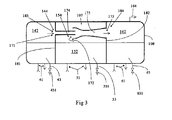
- Fig. 3 shows an embodiment of an integrated steam drum and steam ejector arrangement.
- reference numeral 1 indicates an internal combustion engine which provides a gas flow 2 to a boiler unit 3.
- the boiler unit 3 comprises a first evaporator 4, a third evaporator 6 and a second evaporator 5 arranged one after another in this order in the direction of the gas flow.
- the first evaporator 4 is connected to a first fluid circuit 41 provided with a first steam drum 42.
- the first steam drum 42 is provided with a first fluid feeding means 43 and a first steam outlet 44.
- the fluid i.e. normally water, is fed into the first steam drum 42 by means of the first fluid feeding means 43 and is then circulated in the first fluid circuit 41 through the first evaporator 4 by a first pump 45 in order to generate high pressure steam in the first steam drum 42.
- the high pressure steam is released from the first steam drum 42 by way of the first steam outlet 44.
- the third evaporator 6 is connected to a third fluid circuit 61 provided with a third steam drum 62.
- the third steam drum 62 is provided with a third fluid feeding means 63 and a third steam outlet 64.
- the fluid i.e. normally water, is fed into the third steam drum 62 by means of the third fluid feeding means 63 and is then circulated in the third fluid circuit 61 through the third evaporator 6 by a third pump 65 in order to generate steam having a given desired pressure in the third steam drum 62. Steam having a given desired pressure is released from the third steam drum 62 by way of the third steam outlet 64.
- the second evaporator 5 is connected to a second fluid circuit 51 provided with a second steam drum 52.
- the second steam drum 52 is provided with a second fluid feeding means 53 and a second steam outlet 54.
- the fluid i.e. normally water, is fed into the second steam drum 52 by means of the second fluid feeding means 53 and is then circulated in the second fluid circuit 51 through the second evaporator 5 by a second pump 55 in order to generate low pressure steam in the second steam drum 52.
- the low pressure steam is released from the second steam drum 52 by way of the second steam outlet 54.
- the system further comprises a steam ejector 7 with a high pressure steam inlet 71, a low pressure steam inlet 72 and a fourth steam outlet 73.
- the steam ejector is used to raise the pressure of the low pressure steam to a given desired pressure by means of the high pressure steam.
- High pressure steam generated by the first evaporator 4 is led to the high pressure steam inlet 71 of the steam ejector 7 and low pressure steam generated by the second evaporator 5 is led to the low pressure steam inlet 72 of the steam ejector 7, whereby the high pressure steam is used as a drive fluid for the steam ejector so that the resulting ejector effect generates steam having a given desired pressure from the fourth steam outlet 73.
- This steam is then brought together with steam, having the same given desired pressure, generated by the third evaporator 6 (described above) in order to increase the production of steam with a given desired pressure, so-called useful steam.
- the method according to the invention generally works as follows.
- each fluid circuit fluid is fed into the steam drum by means of the fluid feeding means and is then pumped by the pump means into circulation through the evaporator, from where it is led back to the upper part of the steam drum as steam that is released from the steam outlet.
- the high grade heat energy (due to the high incoming temperature of the exhaust gas) is recovered and converted into a high pressure steam with a pressure that normally is higher than what e.g. is suitable for use as an industrial process steam or steam for a steam turbine (so-called useful steam).
- This high pressure steam is led from the first steam outlet 44 to the steam ejector 7 to be used as a drive fluid.
- the third evaporator 6 As the gas flow reaches the third evaporator 6 it naturally has cooled of to some degree and is used to generate steam of a given desired pressure suitable for the intended use, e.g. for the above mentioned purposes, from the third steam outlet 64.
- the gas flow reaches the second evaporator 5 where the cooled gas flow at the end of the boiler unit 3 provides low grade heat energy (due to a significantly lowered temperature) which is used to generate a low pressure steam with a pressure that normally is lower than what e.g. is suitable for use as described above.
- This low pressure steam is then led from the second steam outlet 54 to the steam ejector 7, in which the above mentioned high pressure steam is used to boost the low pressure up to a given desired pressure.
- the result is that the amount of recovered heat energy in the form of a given desired steam pressure from the same gas flow is higher than what has been possible by previously known solutions.
- the third evaporator 6 and the thereto related third fluid circuit 61, third steam drum 62, third fluid inlet 63, third steam outlet 64 and third pump 65 can be left out of the system, whereby steam with a given desired pressure may be produced only by means of the steam ejector 7.
- Fig. 2 shows another embodiment of the present invention. This embodiment follows the general set up of the embodiment described in Fig. 1 , whereby also the same reference numerals are used to indicate corresponding parts as described in connection with Fig. 1 . The main difference may be found in the arrangement of the steam drums and the steam ejector.
- the steam drums i.e. the first steam drum 42, the second steam drum 52 and the third steam drum 62 are integrated into one unit, in this case a receptacle 8, one after another in this order.
- the receptacle 8 is provided with a first partition wall 81 and a second partition wall 82.
- the partition walls divide the receptacle 8 into a first section forming the first steam drum 42, a second section forming the second steam drum 52 and a third section forming the third steam drum 62 in this order, whereby the first partition wall 81 separates the first steam drum 42 and the second steam drum 52 and the second partition wall 82 separates the second steam drum 52 and the third steam drum 62.
- the first steam drum 42, the second steam drum 52 and the third steam drum 62 have their respective first fluid feeding means 43, second fluid feeding means 53 and third fluid feeding means 63, which are connected to a common fluid source 9 through respective first valve means 431, second valve means 531 and third valve means 631.
- the first steam drum 42 is provided with a first steam outlet 44 for feeding high pressure steam to the high pressure steam inlet 71 of the steam ejector 7 and the second steam drum 52 is provided with a second steam outlet 54 for feeding low pressure steam into the low pressure steam inlet 72 of the steam ejector 7.
- Steam, having a given desired pressure, generated by the steam ejector 7 from the fourth steam outlet 73 is arranged to be brought together with steam, also having a given desired pressure, generated in the third steam drum 62 and released from the corresponding third steam outlet 64.
- This system may also be operated without the third evaporator 6 by closing of the corresponding fluid feeding means 63 with the third valve means 631 and the corresponding third fluid circuit 61 as described in connection with Fig. 1 above.
- FIG. 1 and 2 there is also shown an additional separate source of heat (typically low grade heat) for heat recovery, which source is indicated by reference numeral 200.
- Heat recovery is made by a heat exchanger 201, which may be connected to the second fluid circuit 51, if so desired.
- the number of evaporators and steam ejectors may be increased. This would mean that low pressure steam and high pressure steam would be generated at different pressure levels, which then could be raised by corresponding ejectors and correspondingly brought together with steam having a given desired pressure.
- the steam circuits could thus be combined in order to optimise the degree of heat recovery.
- the evaporators, and the corresponding ejectors can be arranged in one or more boiler units, e.g. depending on the source and volume of gas flow.
- Fig. 3 shows a further embodiment of an integrated steam drum arrangement provided with a steam ejector 107.
- the steam drums i.e. the first steam drum 142, the second steam drum 152 and the third steam drum 162 are integrated into one unit, in this case a receptacle 108, one after another in this order.
- the receptacle 108 is provided with a first partition wall 181 and a second partition wall 182.
- the partition walls divide the receptacle 108 into a first section forming the first steam drum 142, a second section forming the second steam drum 152 and a third section forming the third steam drum 162, whereby the first partition wall 181 separates the first steam drum 142 and the second steam drum 152 and the second partition wall 182 separates the second steam drum 152 and the third steam drum 162.
- the first steam drum 142, the second steam drum 152 and the third steam drum 162 are connected to a first fluid circuit 41 and a first fluid feeding means 43 provided with a first valve 431, a second fluid circuit 51 and a second fluid feeding means 53 provided with a second valve 531, and a third fluid circuit 61 and a third fluid feeding means 63 provided with a third valve 631 respectively, as described in connection with Fig. 2 above.
- the steam ejector 107 is integrated into the structure of the receptacle 108, in the second section forming the second steam drum 152.
- the first steam outlet 144 of the first steam drum 142 is arranged as a first opening 183 in the first partition wall 181 and leads to the high pressure steam inlet 171 of the steam ejector 107 and the second steam outlet 154 of the second steam drum 152 actually forms the low pressure steam inlet 172 of the steam ejector 107.
- the fourth steam outlet 173 of the steam ejector 107 is arranged as a second opening 184 in the second partition wall 182 and leads to the third steam drum 162.
- a simple way to construct this arrangement is to fix a first end of a first ejector pipe 174 to the first opening 183 in the first partition wall 181 to form the high pressure steam 171 inlet and a second end of a second ejector pipe 175 to the second opening 184 in the second partition wall 182 to form the fourth steam outlet 173.
- the second end, opposite to the first end, of the first ejector pipe 174 is then arranged to extend into a first enlarged end, opposite the second end, of the second ejector pipe 175 to form an annular low pressure steam inlet 172.
- the ejector effect is then achieved when high pressure steam flows from the first steam drum 142 through the first opening 183 into and through the first ejector pipe 174 drawing low pressure steam from the second steam drum 152 by way of the annular low pressure steam inlet 172 into the second ejector pipe 175, thus boosting the pressure of the low pressure steam in order to eject steam having a given desired pressure from the fourth steam outlet 173 of the steam ejector 107 into the third steam drum 162 containing steam of the same pressure provided from the third fluid circuit 61.
- the resulting steam may then be led out of the third steam outlet 164 of the third steam drum 162.
- the gas flow may e.g. be flue gas
- the fluid used for steam generation may be a liquid solution
- the fluid circuits may be provided with control means for further process regulation, etc. within the scope of the ensuing claims.
Landscapes
- Engineering & Computer Science (AREA)
- Mechanical Engineering (AREA)
- General Engineering & Computer Science (AREA)
- Chemical & Material Sciences (AREA)
- Combustion & Propulsion (AREA)
- Physics & Mathematics (AREA)
- Thermal Sciences (AREA)
- Life Sciences & Earth Sciences (AREA)
- Sustainable Development (AREA)
- Sustainable Energy (AREA)
- Control Of Steam Boilers And Waste-Gas Boilers (AREA)
- Jet Pumps And Other Pumps (AREA)
Description
- The present invention relates to a method for heat recovery from a gas flow, in which method gas is led into a boiler unit comprising at least an evaporator connected to a fluid circuit for generating steam according to the preamble of
claim 1. The present invention also relates to a corresponding system according to the preamble of claim 9. - It is previously known to recover heat from a gas flow, e.g. a flow of hot exhaust gas from an internal combustion engine. An example of such a solution may be found in patent publication
FI 105 717 SE 517 753 US-A-4753079 andFR-A-1180014 - An object of the present invention is to avoid said disadvantages and to achieve a method and system for heat recovery from a gas flow by which the generation of useful steam is increased by employing simple means. This object is attained by a method according to
claim 1 and a system according to claim 9. - The basic idea of the invention is to minimise the losses in energy conversion in employing evaporator means arranged in a gas flow and used for generating steam. This is realised by using high pressure steam generated by high grade heat energy at the upstream side of the gas flow to boost low pressure steam generated by low grade heat energy at the downstream side of the same gas flow. In practice this is done by employing a method according to
independent claim 1 and a system according toindependent claim 7. - This allows for reducing the temperature of the exhaust gas flow to a level that is lower than what would normally be possible in order to generate steam having a given desired pressure based on a given incoming temperature of the fluid fed to the fluid circuits. In other words according to the present invention the amount of recovered heat energy in the form of steam at a certain pressure from the same gas flow is higher than in previously known solutions.
- A more effective way for heat recovery in order to increase steam production is to place a third evaporator connected to a third fluid circuit between the first evaporator and the second evaporator in the direction of the gas flow, and to use the third evaporator for generating steam having a given desired pressure. The steam generated by the steam ejector is then brought together with the steam generated by the third evaporator thus increasing efficiency.
- In order to further raise the efficiency the number of evaporators and steam ejectors can be increased, whereby the steam circuits may then be combined to optimise the degree of heat recovery.
- The evaporators, and the corresponding ejectors, can be arranged in one or more boiler units, e.g. depending on the source of the gas flow.
- A preferred source of gas flow is the exhaust gas from an internal combustion engine, e.g. a diesel engine.
- The system according to the present invention for heat recovery from a gas flow comprises a boiler unit provided with at least an evaporator connected to a fluid circuit for generating steam. This system may advantageously may be employed in the method according to the invention described above.
- In an advantageous and simple arrangement for such a system providing an efficiently and easily controllable process flow the first fluid circuit is provided with a first steam drum with a first fluid feeding means and a first steam outlet and the second fluid circuit is provided with a second steam drum with a second fluid feeding means and a second steam outlet. The first steam outlet is connected to a high pressure steam inlet of the steam ejector and the second steam outlet is connected a low pressure steam inlet of the steam ejector.
- If a third evaporator is used, a correspondingly advantageous arrangement is that the third fluid circuit comprises a third steam drum provided with a third fluid feeding means and a third steam outlet. The steam ejector is provided with a fourth steam outlet connected to the third steam outlet so that the steam generated by the steam ejector may be brought together with the steam generated by the third evaporator.
- To make the system more compact and to reduce e.g. internal piping, the first steam drum, the second steam drum and the third steam drum are integrated into one unit, preferably a receptacle.
- The receptacle is provided with a first partition wall and a second partition wall dividing the receptacle into a first section forming the first steam drum, a second section forming the second steam drum and a third section forming the third steam drum in this order.
- A further degree of integration may be achieved in that the steam ejector is arranged in the second section. The first steam outlet may be arranged as a first opening in the first partition wall in order to form the high pressure steam inlet of the steam ejector and the low pressure steam inlet of the steam ejector is formed by the second steam outlet, whereby the fourth steam outlet is arranged in the second partition wall.
- A simple ejector construction may be achieved by attaching a first end of a first ejector pipe to the first opening, forming the high pressure steam inlet, and by attaching a second end of a second ejector pipe to the second opening. A second end of the first ejector pipe may then extend into an enlarged first end of the second ejector pipe to form the low pressure steam inlet.
- Further advantageous features of the method and system according to the present invention are given in the dependent claims.
- In the following the present invention is described more in detail, by way of example only, with reference to the attached schematic drawings, in which
-
Fig. 1 shows a flow sheet of a first embodiment of the invention, -
Fig. 2 shows a flow sheet of a second embodiment of the invention, and -
Fig. 3 shows an embodiment of an integrated steam drum and steam ejector arrangement. - In the system shown in
Fig. 1 reference numeral 1 indicates an internal combustion engine which provides agas flow 2 to aboiler unit 3. This could for example be a diesel engine, whereby the flow of gas would be the exhaust gas from this engine. Theboiler unit 3 comprises afirst evaporator 4, athird evaporator 6 and asecond evaporator 5 arranged one after another in this order in the direction of the gas flow. - The
first evaporator 4 is connected to afirst fluid circuit 41 provided with afirst steam drum 42. Thefirst steam drum 42 is provided with a first fluid feeding means 43 and afirst steam outlet 44. The fluid, i.e. normally water, is fed into thefirst steam drum 42 by means of the first fluid feeding means 43 and is then circulated in thefirst fluid circuit 41 through thefirst evaporator 4 by afirst pump 45 in order to generate high pressure steam in thefirst steam drum 42. The high pressure steam is released from thefirst steam drum 42 by way of thefirst steam outlet 44. - The
third evaporator 6 is connected to athird fluid circuit 61 provided with athird steam drum 62. Thethird steam drum 62 is provided with a third fluid feeding means 63 and athird steam outlet 64. The fluid, i.e. normally water, is fed into thethird steam drum 62 by means of the third fluid feeding means 63 and is then circulated in thethird fluid circuit 61 through thethird evaporator 6 by athird pump 65 in order to generate steam having a given desired pressure in thethird steam drum 62. Steam having a given desired pressure is released from thethird steam drum 62 by way of thethird steam outlet 64. - The
second evaporator 5 is connected to asecond fluid circuit 51 provided with asecond steam drum 52. Thesecond steam drum 52 is provided with a second fluid feeding means 53 and asecond steam outlet 54. The fluid, i.e. normally water, is fed into thesecond steam drum 52 by means of the second fluid feeding means 53 and is then circulated in thesecond fluid circuit 51 through thesecond evaporator 5 by asecond pump 55 in order to generate low pressure steam in thesecond steam drum 52. The low pressure steam is released from thesecond steam drum 52 by way of thesecond steam outlet 54. - The system further comprises a
steam ejector 7 with a highpressure steam inlet 71, a lowpressure steam inlet 72 and afourth steam outlet 73. The steam ejector is used to raise the pressure of the low pressure steam to a given desired pressure by means of the high pressure steam. High pressure steam generated by thefirst evaporator 4 is led to the highpressure steam inlet 71 of thesteam ejector 7 and low pressure steam generated by thesecond evaporator 5 is led to the lowpressure steam inlet 72 of thesteam ejector 7, whereby the high pressure steam is used as a drive fluid for the steam ejector so that the resulting ejector effect generates steam having a given desired pressure from thefourth steam outlet 73. This steam is then brought together with steam, having the same given desired pressure, generated by the third evaporator 6 (described above) in order to increase the production of steam with a given desired pressure, so-called useful steam. - The method according to the invention generally works as follows.
- Hot exhaust gas from the
internal combustion engine 1, for example a diesel engine, is led as agas flow 2 to theboiler unit 3 where it flows past the series of evaporators and leaves theboiler unit 3 as a cooledgas flow 21. - In each fluid circuit fluid is fed into the steam drum by means of the fluid feeding means and is then pumped by the pump means into circulation through the evaporator, from where it is led back to the upper part of the steam drum as steam that is released from the steam outlet.
- At the
first evaporator 4 the high grade heat energy (due to the high incoming temperature of the exhaust gas) is recovered and converted into a high pressure steam with a pressure that normally is higher than what e.g. is suitable for use as an industrial process steam or steam for a steam turbine (so-called useful steam). This high pressure steam is led from thefirst steam outlet 44 to thesteam ejector 7 to be used as a drive fluid. - As the gas flow reaches the
third evaporator 6 it naturally has cooled of to some degree and is used to generate steam of a given desired pressure suitable for the intended use, e.g. for the above mentioned purposes, from thethird steam outlet 64. - After further cooling, the gas flow reaches the
second evaporator 5 where the cooled gas flow at the end of theboiler unit 3 provides low grade heat energy (due to a significantly lowered temperature) which is used to generate a low pressure steam with a pressure that normally is lower than what e.g. is suitable for use as described above. This low pressure steam is then led from thesecond steam outlet 54 to thesteam ejector 7, in which the above mentioned high pressure steam is used to boost the low pressure up to a given desired pressure. - Steam generated in the
third fluid circuit 61 by thethird evaporator 6 is then brought together with steam generated by thesteam ejector 7 resulting in an increased production of so-called useful steam having a given desired pressure. - Basically this means that the temperature of the exhaust gas flow can be reduced to a level that is lower than what would be possible in order to generate steam having a given desired pressure based on a given incoming temperature of the fluid. The result is that the amount of recovered heat energy in the form of a given desired steam pressure from the same gas flow is higher than what has been possible by previously known solutions.
- The
third evaporator 6 and the thereto relatedthird fluid circuit 61,third steam drum 62, thirdfluid inlet 63,third steam outlet 64 andthird pump 65 can be left out of the system, whereby steam with a given desired pressure may be produced only by means of thesteam ejector 7. -
Fig. 2 shows another embodiment of the present invention. This embodiment follows the general set up of the embodiment described inFig. 1 , whereby also the same reference numerals are used to indicate corresponding parts as described in connection withFig. 1 . The main difference may be found in the arrangement of the steam drums and the steam ejector. - The steam drums, i.e. the
first steam drum 42, thesecond steam drum 52 and thethird steam drum 62 are integrated into one unit, in this case areceptacle 8, one after another in this order. Thereceptacle 8 is provided with afirst partition wall 81 and asecond partition wall 82. The partition walls divide thereceptacle 8 into a first section forming thefirst steam drum 42, a second section forming thesecond steam drum 52 and a third section forming thethird steam drum 62 in this order, whereby thefirst partition wall 81 separates thefirst steam drum 42 and thesecond steam drum 52 and thesecond partition wall 82 separates thesecond steam drum 52 and thethird steam drum 62. - The
first steam drum 42, thesecond steam drum 52 and thethird steam drum 62 have their respective first fluid feeding means 43, second fluid feeding means 53 and third fluid feeding means 63, which are connected to a common fluid source 9 through respective first valve means 431, second valve means 531 and third valve means 631. - The
first steam drum 42 is provided with afirst steam outlet 44 for feeding high pressure steam to the highpressure steam inlet 71 of thesteam ejector 7 and thesecond steam drum 52 is provided with asecond steam outlet 54 for feeding low pressure steam into the lowpressure steam inlet 72 of thesteam ejector 7. - Steam, having a given desired pressure, generated by the
steam ejector 7 from thefourth steam outlet 73 is arranged to be brought together with steam, also having a given desired pressure, generated in thethird steam drum 62 and released from the correspondingthird steam outlet 64. - The working process described in connection with
Fig. 1 above is also applicable to this embodiment. - This system may also be operated without the
third evaporator 6 by closing of the corresponding fluid feeding means 63 with the third valve means 631 and the corresponding thirdfluid circuit 61 as described in connection withFig. 1 above. - In connection with
Figs. 1 and 2 there is also shown an additional separate source of heat (typically low grade heat) for heat recovery, which source is indicated byreference numeral 200. Heat recovery is made by aheat exchanger 201, which may be connected to thesecond fluid circuit 51, if so desired. - In both embodiments it would further be possible to provide a superheater, which would be placed in the same gas flow before the
first evaporator 4. Further, a supplementary pre-heater could be arranged in the same gas flow either after or parallel with the second evaporator. This option could be used, if it would be useful for the end process in question. - In order to further raise the efficiency the number of evaporators and steam ejectors may be increased. This would mean that low pressure steam and high pressure steam would be generated at different pressure levels, which then could be raised by corresponding ejectors and correspondingly brought together with steam having a given desired pressure. The steam circuits could thus be combined in order to optimise the degree of heat recovery.
- The evaporators, and the corresponding ejectors, can be arranged in one or more boiler units, e.g. depending on the source and volume of gas flow.
-
Fig. 3 shows a further embodiment of an integrated steam drum arrangement provided with asteam ejector 107. - The steam drums, i.e. the
first steam drum 142, thesecond steam drum 152 and thethird steam drum 162 are integrated into one unit, in this case areceptacle 108, one after another in this order. Thereceptacle 108 is provided with afirst partition wall 181 and asecond partition wall 182. The partition walls divide thereceptacle 108 into a first section forming thefirst steam drum 142, a second section forming thesecond steam drum 152 and a third section forming thethird steam drum 162, whereby thefirst partition wall 181 separates thefirst steam drum 142 and thesecond steam drum 152 and thesecond partition wall 182 separates thesecond steam drum 152 and thethird steam drum 162. - The
first steam drum 142, thesecond steam drum 152 and thethird steam drum 162 are connected to afirst fluid circuit 41 and a first fluid feeding means 43 provided with afirst valve 431, asecond fluid circuit 51 and a second fluid feeding means 53 provided with asecond valve 531, and a thirdfluid circuit 61 and a third fluid feeding means 63 provided with athird valve 631 respectively, as described in connection withFig. 2 above. - In this embodiment, however, the
steam ejector 107 is integrated into the structure of thereceptacle 108, in the second section forming thesecond steam drum 152. Thefirst steam outlet 144 of thefirst steam drum 142 is arranged as afirst opening 183 in thefirst partition wall 181 and leads to the highpressure steam inlet 171 of thesteam ejector 107 and thesecond steam outlet 154 of thesecond steam drum 152 actually forms the lowpressure steam inlet 172 of thesteam ejector 107. Thefourth steam outlet 173 of thesteam ejector 107 is arranged as asecond opening 184 in thesecond partition wall 182 and leads to thethird steam drum 162. - A simple way to construct this arrangement is to fix a first end of a
first ejector pipe 174 to thefirst opening 183 in thefirst partition wall 181 to form thehigh pressure steam 171 inlet and a second end of asecond ejector pipe 175 to thesecond opening 184 in thesecond partition wall 182 to form thefourth steam outlet 173. The second end, opposite to the first end, of thefirst ejector pipe 174 is then arranged to extend into a first enlarged end, opposite the second end, of thesecond ejector pipe 175 to form an annular lowpressure steam inlet 172. - The ejector effect is then achieved when high pressure steam flows from the
first steam drum 142 through thefirst opening 183 into and through thefirst ejector pipe 174 drawing low pressure steam from thesecond steam drum 152 by way of the annular lowpressure steam inlet 172 into thesecond ejector pipe 175, thus boosting the pressure of the low pressure steam in order to eject steam having a given desired pressure from thefourth steam outlet 173 of thesteam ejector 107 into thethird steam drum 162 containing steam of the same pressure provided from the thirdfluid circuit 61. The resulting steam may then be led out of thethird steam outlet 164 of thethird steam drum 162. - The working process described in connection with
Fig. 1 above is also applicable to this embodiment. - The drawings and the description related thereto are only intended for clarification of the basic idea of the invention. The invention may vary in further detail, e.g. the gas flow may e.g. be flue gas, the fluid used for steam generation may be a liquid solution, the fluid circuits may be provided with control means for further process regulation, etc. within the scope of the ensuing claims.
Claims (16)
- Method for heat recovery from a gas flow (2), in which method gas is led into a boiler unit (3) comprising at least an evaporator connected to a fluid circuit for generating steam, characterised in that the method employs at least three evaporators, that gas is led in the direction of the gas flow (2) past a first evaporator (4) connected to a first fluid circuit (41), then past a third evaporator (6) connected to a third fluid circuit (61), and subsequently past a second evaporator (6) connected to a second fluid circuit (51), that the first evaporator (4) is used to generate high pressure steam, the third evaporator (6) is used to generate steam having a given desired pressure, and the second evaporator (5) is used to generate low pressure steam, and in that high pressure steam and low pressure steam are led to a steam ejector (7) for raising the pressure of the low pressure steam in order to generate steam having said given desired pressure, which is brought together with steam having said given desired pressure generated by the third evaporator (6).
- Method according to claim 1, characterised in that fluid is led to a first fluid inlet (43) of a first steam drum (42) provided in the first fluid circuit (41) and circulated through the first evaporator (4) and back into the first steam drum (4) in order to generate high pressure steam, that fluid is led to a second fluid inlet (53) of a second steam drum (52) provided in the second fluid circuit (51) and circulated through the second evaporator (5) and back into the second steam drum (52) in order to generate low pressure steam, that fluid is led to a third fluid inlet (63) of a third steam drum (62) provided in the third fluid circuit (61) and circulated through the third evaporator (6) and back into the third steam drum (6) in order to generate steam having said given desired pressure, that high pressure steam is led to a high pressure steam inlet (71) of the steam ejector (7) and low pressure steam is lead to a low pressure steam inlet (72) of the steam ejector (7) for raising the pressure of the low pressure steam in order to generate steam having said given desired pressure from a fourth steam outlet (73) of the steam ejector (7), and in that steam generated by the steam ejector (7) is brought together with steam having said given desired pressure generated in the third steam drum (6).
- Method according to claim 1, characterised in that the system employs a plurality of evaporators, that gas is led past the evaporators arranged one after another in the direction of the gas flow, that one or more evaporator is used to generate high pressure steam, that one or more evaporator is used to generate low pressure steam, and in that high pressure steam and low pressure steam are led to one or more steam ejector for raising the pressure of the low pressure steam in order to generate steam having said given desired pressure.
- Method according to claim 3, characterised in that one or more evaporator is used to generate steam with said given desired pressure, and in that steam generated by the one or more steam ejector is brought together with steam having said given desired pressure generated by said one or more evaporator.
- Method according to claim 5, characterised in that the method employs one or more boiler unit (3).
- Method according to claim 1, characterised in that the gas used is exhaust gas from an internal combustion engine (1).
- System for heat recovery from a gas flow, which system comprises a boiler unit (3) provided with at least an evaporator connected to a fluid circuit for generating steam, characterised in that the system comprises at least three evaporators in the direction of the gas flow (2), a first evaporator (4) connected to a first fluid circuit (41), a second evaporator (5) connected to a second fluid circuit (51), and a third evaporator (6) connected to a third fluid circuit (61) and arranged between the first evaporator (4) and the second evaporator (5) in the direction of the gas flow (2), that the first evaporator (4) is arranged to generate high pressure steam, the second evaporator (5) is arranged to generate low pressure steam, the first evaporator (4) and the second evaporator (5) are connected to a steam ejector (7), which is arranged to generate steam having a given desired pressure, that the third evaporator (6) is arranged to generate steam having said given desired pressure, and in that the steam having said given desired pressure generated by the steam ejector (7) is arranged to be brought together with steam having said given desired pressure generated by the third evaporator (6).
- System according to claim 7, characterised in that the first fluid circuit (41) is provided with a first steam drum (42) with a first fluid feeding means (43) and a first steam outlet (44), that the second fluid circuit (51) is provided with a second steam drum (52) with a second fluid feeding means (53) and a second steam outlet (54), that the first steam outlet (44) is connected to a high pressure steam inlet (71) of the steam ejector (7) and the second steam outlet (54) is connected a low pressure steam inlet (72) of the steam ejector (7), and in that that the third fluid circuit (61) comprises a third steam drum (62) provided with a third fluid feeding means (63) and a third steam outlet (64), and in that the steam ejector (7) is provided with a fourth steam outlet (73) connected to the third steam outlet (64).
- System according to claim 8, characterised in that the first steam drum (42), the second steam drum (52) and the third steam drum (62) are integrated into one unit.
- System according to claim 9, characterised in that the first steam drum (42), the second steam drum (52) and the third steam drum (62) are integrated into a receptacle (8), and in that the receptacle (8) is provided with a first partition wall (81) and a second partition wall (82) dividing the receptacle into a first section forming the first steam drum (42), a second section forming the second steam drum (52) and a third section forming the third steam drum (62) in this order.
- System according to claim 10, characterised in that the steam ejector (107) is arranged in the second section, that the first steam outlet (144) of the first steam drum (142) is formed by a first opening (183) in the first partition wall (181), that the high pressure steam inlet (171) of the steam ejector (107) is formed by said first opening (183), that the low pressure steam inlet (172) of the steam ejector (107) is formed by the second steam outlet (154) of the second steam drum (162), and in that the fourth steam outlet (173) of the steam ejector (107) is formed by a second opening (184) in the second partition wall (182).
- System according to claim 11, characterised in that the steam ejector (107) comprises a first ejector pipe (174) having a first end fixed to the first opening (183) and a second ejector pipe (175) having a second end fixed to the second opening (184), and in that a second end of the first ejector pipe (174) extends into an enlarged first end of the second ejector pipe (1 75) in order to form an annular low pressure inlet (172) of the steam ejector (107).
- System according to claim 8, characterised in that the system comprises a plurality of evaporators arranged one after another in the direction of the gas flow, each evaporator being connected to a fluid circuit, that one or more evaporator is arranged to generate high pressure steam, that one or more evaporator is arranged to generate low pressure steam, and in that said one or more evaporator arranged to generate high pressure steam and said one or more evaporator arranged to generate low pressure steam are connected to the one or more steam ejector.
- System according to claim 13, characterised in that one or more evaporator is arranged to generate steam with said given desired pressure, and in the one or more steam ejector is provided with a steam outlet connected to a steam outlet of said one or more evaporator,
- System according to claim 17, characterised in that the system comprises one or more boiler unit (3).
- System according to claim 9, characterised in that the system is connected to an internal combustion engine (1) which is arranged to produce exhaust gas for the gas flow (2).
Applications Claiming Priority (2)
| Application Number | Priority Date | Filing Date | Title |
|---|---|---|---|
| FI20045419A FI118237B (en) | 2004-11-03 | 2004-11-03 | Procedure and arrangement for heat recovery |
| PCT/FI2005/050371 WO2006048505A1 (en) | 2004-11-03 | 2005-10-24 | Method and system for heat recovery |
Publications (2)
| Publication Number | Publication Date |
|---|---|
| EP1807608A1 EP1807608A1 (en) | 2007-07-18 |
| EP1807608B1 true EP1807608B1 (en) | 2012-12-19 |
Family
ID=33515302
Family Applications (1)
| Application Number | Title | Priority Date | Filing Date |
|---|---|---|---|
| EP05799487A Expired - Lifetime EP1807608B1 (en) | 2004-11-03 | 2005-10-24 | Method and system for heat recovery |
Country Status (4)
| Country | Link |
|---|---|
| EP (1) | EP1807608B1 (en) |
| DK (1) | DK1807608T3 (en) |
| FI (1) | FI118237B (en) |
| WO (1) | WO2006048505A1 (en) |
Families Citing this family (3)
| Publication number | Priority date | Publication date | Assignee | Title |
|---|---|---|---|---|
| CN101865448B (en) * | 2010-07-19 | 2012-07-18 | 李树生 | Chimney waste heat steam boiler |
| CN109312635B (en) | 2016-06-17 | 2021-02-05 | 西门子股份公司 | Condensate recirculation |
| CN110388634A (en) * | 2018-04-16 | 2019-10-29 | 哈尔滨工大金涛科技股份有限公司 | A kind of flash vessel |
Family Cites Families (5)
| Publication number | Priority date | Publication date | Assignee | Title |
|---|---|---|---|---|
| FR1180014A (en) * | 1956-04-13 | 1959-06-01 | Method of reconciling the cycles of steam, the carnot cycle, called | |
| US3769795A (en) * | 1972-03-22 | 1973-11-06 | Turbo Power And Marines Syst I | Multipressure steam system for unfired combined cycle powerplant |
| JPS62206302A (en) * | 1986-03-05 | 1987-09-10 | 株式会社 日阪製作所 | evaporator |
| DE19541543C2 (en) * | 1995-11-08 | 1997-10-16 | Steag Ag | Method and arrangement for preheating the main condensate in power plant processes |
| DE19736885A1 (en) * | 1997-08-25 | 1999-03-04 | Siemens Ag | Steam generator, in particular waste heat steam generator and method for operating this steam generator |
-
2004
- 2004-11-03 FI FI20045419A patent/FI118237B/en not_active IP Right Cessation
-
2005
- 2005-10-24 DK DK05799487.3T patent/DK1807608T3/en active
- 2005-10-24 EP EP05799487A patent/EP1807608B1/en not_active Expired - Lifetime
- 2005-10-24 WO PCT/FI2005/050371 patent/WO2006048505A1/en not_active Ceased
Also Published As
| Publication number | Publication date |
|---|---|
| WO2006048505A1 (en) | 2006-05-11 |
| FI20045419L (en) | 2006-05-04 |
| EP1807608A1 (en) | 2007-07-18 |
| FI118237B (en) | 2007-08-31 |
| FI20045419A0 (en) | 2004-11-03 |
| DK1807608T3 (en) | 2013-01-21 |
Similar Documents
| Publication | Publication Date | Title |
|---|---|---|
| EP2199720B1 (en) | Double-pressure type condenser, and condensate reheating method | |
| US7681396B2 (en) | Steam turbine with heating steam extraction and power plant with steam turbine | |
| EP2689185B1 (en) | Method and configuration to reduce fatigue in steam drums | |
| EP2584157B1 (en) | Heat recovery steam generator and methods of coupling same to a combined cycle power plant | |
| CN101644192B (en) | System und anordnungen zur heisswasserentnahme zum vorheizen von brennstoff in einem kombizykluskraftwerk | |
| CN103154445B (en) | Method for operating combined-cycle power plant with cogeneration and combined-cycle power plant for carrying out the method | |
| CN212079408U (en) | Hydrophobic recycle system of gas steam combined cycle unit | |
| US20100031660A1 (en) | System and assemblies for pre-heating fuel in a combined cycle power plant | |
| CN109404075B (en) | Small turbine backpressure control thermodynamic system and control method thereof | |
| CN1119513C (en) | Gas and steam turbine installation | |
| SE502492C2 (en) | Boiler system with common steam system | |
| CN216953000U (en) | Steam generating device and system thereof | |
| EP1807608A1 (en) | Method and system for heat recovery | |
| JPH03221702A (en) | Duplex type heat exchanger for waste heat recovery | |
| RU2602649C2 (en) | Steam turbine npp | |
| CN108072030A (en) | For the heat regenerative system of high parameter double reheat power generation sets | |
| JPH11173768A (en) | Multistage pressure condenser | |
| CN108626715B (en) | Heat recovery system with multi-stage deaerator | |
| EP3870896A1 (en) | Steam boiler for waste incineration | |
| US20040040303A1 (en) | Method of and apparatus for increasing the output of a geothermal steam power plant | |
| JPS6035104A (en) | Super high-temperatue, high-pressure steam turbine plant | |
| CN114087602A (en) | A secondary reheating system with an integrated small machine for frequency conversion power generation and heat recovery | |
| EP3486440B1 (en) | Heat recovery steam generator, method for generating steam for a steam turbine and system comprising a steam turbine and a heat recovery steam generator | |
| CN106090985B (en) | A kind of method for heating NOx water fillings and improving combined-cycle power plant's performance | |
| CN113294216B (en) | Subcritical once reheating deep back pressure unit process system for cogeneration |
Legal Events
| Date | Code | Title | Description |
|---|---|---|---|
| PUAI | Public reference made under article 153(3) epc to a published international application that has entered the european phase |
Free format text: ORIGINAL CODE: 0009012 |
|
| 17P | Request for examination filed |
Effective date: 20070416 |
|
| AK | Designated contracting states |
Kind code of ref document: A1 Designated state(s): AT BE BG CH CY CZ DE DK EE ES FI FR GB GR HU IE IS IT LI LT LU LV MC NL PL PT RO SE SI SK TR |
|
| DAX | Request for extension of the european patent (deleted) | ||
| GRAP | Despatch of communication of intention to grant a patent |
Free format text: ORIGINAL CODE: EPIDOSNIGR1 |
|
| GRAS | Grant fee paid |
Free format text: ORIGINAL CODE: EPIDOSNIGR3 |
|
| GRAA | (expected) grant |
Free format text: ORIGINAL CODE: 0009210 |
|
| AK | Designated contracting states |
Kind code of ref document: B1 Designated state(s): AT BE BG CH CY CZ DE DK EE ES FI FR GB GR HU IE IS IT LI LT LU LV MC NL PL PT RO SE SI SK TR |
|
| REG | Reference to a national code |
Ref country code: GB Ref legal event code: FG4D |
|
| REG | Reference to a national code |
Ref country code: CH Ref legal event code: EP |
|
| REG | Reference to a national code |
Ref country code: AT Ref legal event code: REF Ref document number: 589539 Country of ref document: AT Kind code of ref document: T Effective date: 20130115 |
|
| REG | Reference to a national code |
Ref country code: DK Ref legal event code: T3 |
|
| REG | Reference to a national code |
Ref country code: DE Ref legal event code: R096 Ref document number: 602005037523 Country of ref document: DE Effective date: 20130221 |
|
| PG25 | Lapsed in a contracting state [announced via postgrant information from national office to epo] |
Ref country code: ES Free format text: LAPSE BECAUSE OF FAILURE TO SUBMIT A TRANSLATION OF THE DESCRIPTION OR TO PAY THE FEE WITHIN THE PRESCRIBED TIME-LIMIT Effective date: 20130330 Ref country code: SE Free format text: LAPSE BECAUSE OF FAILURE TO SUBMIT A TRANSLATION OF THE DESCRIPTION OR TO PAY THE FEE WITHIN THE PRESCRIBED TIME-LIMIT Effective date: 20121219 Ref country code: LT Free format text: LAPSE BECAUSE OF FAILURE TO SUBMIT A TRANSLATION OF THE DESCRIPTION OR TO PAY THE FEE WITHIN THE PRESCRIBED TIME-LIMIT Effective date: 20121219 Ref country code: FI Free format text: LAPSE BECAUSE OF FAILURE TO SUBMIT A TRANSLATION OF THE DESCRIPTION OR TO PAY THE FEE WITHIN THE PRESCRIBED TIME-LIMIT Effective date: 20121219 |
|
| REG | Reference to a national code |
Ref country code: NL Ref legal event code: VDEP Effective date: 20121219 |
|
| REG | Reference to a national code |
Ref country code: LT Ref legal event code: MG4D |
|
| PG25 | Lapsed in a contracting state [announced via postgrant information from national office to epo] |
Ref country code: LV Free format text: LAPSE BECAUSE OF FAILURE TO SUBMIT A TRANSLATION OF THE DESCRIPTION OR TO PAY THE FEE WITHIN THE PRESCRIBED TIME-LIMIT Effective date: 20121219 Ref country code: SI Free format text: LAPSE BECAUSE OF FAILURE TO SUBMIT A TRANSLATION OF THE DESCRIPTION OR TO PAY THE FEE WITHIN THE PRESCRIBED TIME-LIMIT Effective date: 20121219 Ref country code: GR Free format text: LAPSE BECAUSE OF FAILURE TO SUBMIT A TRANSLATION OF THE DESCRIPTION OR TO PAY THE FEE WITHIN THE PRESCRIBED TIME-LIMIT Effective date: 20130320 |
|
| PG25 | Lapsed in a contracting state [announced via postgrant information from national office to epo] |
Ref country code: BG Free format text: LAPSE BECAUSE OF FAILURE TO SUBMIT A TRANSLATION OF THE DESCRIPTION OR TO PAY THE FEE WITHIN THE PRESCRIBED TIME-LIMIT Effective date: 20130319 Ref country code: CZ Free format text: LAPSE BECAUSE OF FAILURE TO SUBMIT A TRANSLATION OF THE DESCRIPTION OR TO PAY THE FEE WITHIN THE PRESCRIBED TIME-LIMIT Effective date: 20121219 Ref country code: IS Free format text: LAPSE BECAUSE OF FAILURE TO SUBMIT A TRANSLATION OF THE DESCRIPTION OR TO PAY THE FEE WITHIN THE PRESCRIBED TIME-LIMIT Effective date: 20130419 Ref country code: EE Free format text: LAPSE BECAUSE OF FAILURE TO SUBMIT A TRANSLATION OF THE DESCRIPTION OR TO PAY THE FEE WITHIN THE PRESCRIBED TIME-LIMIT Effective date: 20121219 Ref country code: BE Free format text: LAPSE BECAUSE OF FAILURE TO SUBMIT A TRANSLATION OF THE DESCRIPTION OR TO PAY THE FEE WITHIN THE PRESCRIBED TIME-LIMIT Effective date: 20121219 Ref country code: SK Free format text: LAPSE BECAUSE OF FAILURE TO SUBMIT A TRANSLATION OF THE DESCRIPTION OR TO PAY THE FEE WITHIN THE PRESCRIBED TIME-LIMIT Effective date: 20121219 |
|
| PG25 | Lapsed in a contracting state [announced via postgrant information from national office to epo] |
Ref country code: NL Free format text: LAPSE BECAUSE OF FAILURE TO SUBMIT A TRANSLATION OF THE DESCRIPTION OR TO PAY THE FEE WITHIN THE PRESCRIBED TIME-LIMIT Effective date: 20121219 Ref country code: RO Free format text: LAPSE BECAUSE OF FAILURE TO SUBMIT A TRANSLATION OF THE DESCRIPTION OR TO PAY THE FEE WITHIN THE PRESCRIBED TIME-LIMIT Effective date: 20121219 Ref country code: PT Free format text: LAPSE BECAUSE OF FAILURE TO SUBMIT A TRANSLATION OF THE DESCRIPTION OR TO PAY THE FEE WITHIN THE PRESCRIBED TIME-LIMIT Effective date: 20130419 Ref country code: PL Free format text: LAPSE BECAUSE OF FAILURE TO SUBMIT A TRANSLATION OF THE DESCRIPTION OR TO PAY THE FEE WITHIN THE PRESCRIBED TIME-LIMIT Effective date: 20121219 |
|
| PLBE | No opposition filed within time limit |
Free format text: ORIGINAL CODE: 0009261 |
|
| STAA | Information on the status of an ep patent application or granted ep patent |
Free format text: STATUS: NO OPPOSITION FILED WITHIN TIME LIMIT |
|
| 26N | No opposition filed |
Effective date: 20130920 |
|
| PG25 | Lapsed in a contracting state [announced via postgrant information from national office to epo] |
Ref country code: CY Free format text: LAPSE BECAUSE OF FAILURE TO SUBMIT A TRANSLATION OF THE DESCRIPTION OR TO PAY THE FEE WITHIN THE PRESCRIBED TIME-LIMIT Effective date: 20121219 |
|
| PG25 | Lapsed in a contracting state [announced via postgrant information from national office to epo] |
Ref country code: IT Free format text: LAPSE BECAUSE OF FAILURE TO SUBMIT A TRANSLATION OF THE DESCRIPTION OR TO PAY THE FEE WITHIN THE PRESCRIBED TIME-LIMIT Effective date: 20121219 |
|
| REG | Reference to a national code |
Ref country code: DE Ref legal event code: R097 Ref document number: 602005037523 Country of ref document: DE Effective date: 20130920 |
|
| PG25 | Lapsed in a contracting state [announced via postgrant information from national office to epo] |
Ref country code: MC Free format text: LAPSE BECAUSE OF FAILURE TO SUBMIT A TRANSLATION OF THE DESCRIPTION OR TO PAY THE FEE WITHIN THE PRESCRIBED TIME-LIMIT Effective date: 20121219 |
|
| REG | Reference to a national code |
Ref country code: CH Ref legal event code: PL |
|
| GBPC | Gb: european patent ceased through non-payment of renewal fee |
Effective date: 20131024 |
|
| REG | Reference to a national code |
Ref country code: IE Ref legal event code: MM4A |
|
| PG25 | Lapsed in a contracting state [announced via postgrant information from national office to epo] |
Ref country code: CH Free format text: LAPSE BECAUSE OF NON-PAYMENT OF DUE FEES Effective date: 20131031 Ref country code: GB Free format text: LAPSE BECAUSE OF NON-PAYMENT OF DUE FEES Effective date: 20131024 Ref country code: LI Free format text: LAPSE BECAUSE OF NON-PAYMENT OF DUE FEES Effective date: 20131031 |
|
| REG | Reference to a national code |
Ref country code: FR Ref legal event code: ST Effective date: 20140630 |
|
| PG25 | Lapsed in a contracting state [announced via postgrant information from national office to epo] |
Ref country code: FR Free format text: LAPSE BECAUSE OF NON-PAYMENT OF DUE FEES Effective date: 20131031 |
|
| PG25 | Lapsed in a contracting state [announced via postgrant information from national office to epo] |
Ref country code: IE Free format text: LAPSE BECAUSE OF NON-PAYMENT OF DUE FEES Effective date: 20131024 |
|
| PG25 | Lapsed in a contracting state [announced via postgrant information from national office to epo] |
Ref country code: TR Free format text: LAPSE BECAUSE OF FAILURE TO SUBMIT A TRANSLATION OF THE DESCRIPTION OR TO PAY THE FEE WITHIN THE PRESCRIBED TIME-LIMIT Effective date: 20121219 |
|
| PG25 | Lapsed in a contracting state [announced via postgrant information from national office to epo] |
Ref country code: HU Free format text: LAPSE BECAUSE OF FAILURE TO SUBMIT A TRANSLATION OF THE DESCRIPTION OR TO PAY THE FEE WITHIN THE PRESCRIBED TIME-LIMIT; INVALID AB INITIO Effective date: 20051024 Ref country code: LU Free format text: LAPSE BECAUSE OF NON-PAYMENT OF DUE FEES Effective date: 20131024 |
|
| PGFP | Annual fee paid to national office [announced via postgrant information from national office to epo] |
Ref country code: DE Payment date: 20241021 Year of fee payment: 20 |
|
| PGFP | Annual fee paid to national office [announced via postgrant information from national office to epo] |
Ref country code: DK Payment date: 20241025 Year of fee payment: 20 |
|
| PGFP | Annual fee paid to national office [announced via postgrant information from national office to epo] |
Ref country code: AT Payment date: 20241022 Year of fee payment: 20 |
|
| REG | Reference to a national code |
Ref country code: DE Ref legal event code: R071 Ref document number: 602005037523 Country of ref document: DE |
|
| REG | Reference to a national code |
Ref country code: DK Ref legal event code: EUP Expiry date: 20251024 |
|
| REG | Reference to a national code |
Ref country code: AT Ref legal event code: MK07 Ref document number: 589539 Country of ref document: AT Kind code of ref document: T Effective date: 20251024 |