EP1806875A1 - Method and apparatus for providing call admission control - Google Patents
Method and apparatus for providing call admission control Download PDFInfo
- Publication number
- EP1806875A1 EP1806875A1 EP06290063A EP06290063A EP1806875A1 EP 1806875 A1 EP1806875 A1 EP 1806875A1 EP 06290063 A EP06290063 A EP 06290063A EP 06290063 A EP06290063 A EP 06290063A EP 1806875 A1 EP1806875 A1 EP 1806875A1
- Authority
- EP
- European Patent Office
- Prior art keywords
- call
- telephone
- party
- bandwidth
- access point
- Prior art date
- Legal status (The legal status is an assumption and is not a legal conclusion. Google has not performed a legal analysis and makes no representation as to the accuracy of the status listed.)
- Granted
Links
- 238000000034 method Methods 0.000 title claims abstract description 33
- 230000004044 response Effects 0.000 claims abstract description 20
- 238000004891 communication Methods 0.000 claims description 22
- 230000007246 mechanism Effects 0.000 claims description 14
- 238000012545 processing Methods 0.000 claims description 5
- 230000000977 initiatory effect Effects 0.000 claims description 2
- 230000009471 action Effects 0.000 description 20
- 230000008569 process Effects 0.000 description 12
- 238000004458 analytical method Methods 0.000 description 11
- 230000005540 biological transmission Effects 0.000 description 10
- 230000001960 triggered effect Effects 0.000 description 10
- 238000012360 testing method Methods 0.000 description 8
- 238000012913 prioritisation Methods 0.000 description 4
- 230000004048 modification Effects 0.000 description 3
- 238000012986 modification Methods 0.000 description 3
- 230000004913 activation Effects 0.000 description 2
- 230000008901 benefit Effects 0.000 description 2
- 238000010586 diagram Methods 0.000 description 2
- 230000006870 function Effects 0.000 description 2
- 230000004807 localization Effects 0.000 description 2
- 238000007726 management method Methods 0.000 description 2
- 230000011664 signaling Effects 0.000 description 2
- 230000003068 static effect Effects 0.000 description 2
- 238000012546 transfer Methods 0.000 description 2
- 206010000210 abortion Diseases 0.000 description 1
- 230000003139 buffering effect Effects 0.000 description 1
- 230000008859 change Effects 0.000 description 1
- 230000003247 decreasing effect Effects 0.000 description 1
- 230000000593 degrading effect Effects 0.000 description 1
- 230000001419 dependent effect Effects 0.000 description 1
- 230000006866 deterioration Effects 0.000 description 1
- 230000004941 influx Effects 0.000 description 1
- 230000003993 interaction Effects 0.000 description 1
- 239000000523 sample Substances 0.000 description 1
Images



Classifications
-
- H—ELECTRICITY
- H04—ELECTRIC COMMUNICATION TECHNIQUE
- H04L—TRANSMISSION OF DIGITAL INFORMATION, e.g. TELEGRAPHIC COMMUNICATION
- H04L47/00—Traffic control in data switching networks
- H04L47/70—Admission control; Resource allocation
- H04L47/82—Miscellaneous aspects
- H04L47/824—Applicable to portable or mobile terminals
-
- H—ELECTRICITY
- H04—ELECTRIC COMMUNICATION TECHNIQUE
- H04L—TRANSMISSION OF DIGITAL INFORMATION, e.g. TELEGRAPHIC COMMUNICATION
- H04L47/00—Traffic control in data switching networks
- H04L47/10—Flow control; Congestion control
- H04L47/15—Flow control; Congestion control in relation to multipoint traffic
-
- H—ELECTRICITY
- H04—ELECTRIC COMMUNICATION TECHNIQUE
- H04L—TRANSMISSION OF DIGITAL INFORMATION, e.g. TELEGRAPHIC COMMUNICATION
- H04L47/00—Traffic control in data switching networks
- H04L47/70—Admission control; Resource allocation
-
- H—ELECTRICITY
- H04—ELECTRIC COMMUNICATION TECHNIQUE
- H04L—TRANSMISSION OF DIGITAL INFORMATION, e.g. TELEGRAPHIC COMMUNICATION
- H04L47/00—Traffic control in data switching networks
- H04L47/70—Admission control; Resource allocation
- H04L47/72—Admission control; Resource allocation using reservation actions during connection setup
- H04L47/724—Admission control; Resource allocation using reservation actions during connection setup at intermediate nodes, e.g. resource reservation protocol [RSVP]
-
- H—ELECTRICITY
- H04—ELECTRIC COMMUNICATION TECHNIQUE
- H04L—TRANSMISSION OF DIGITAL INFORMATION, e.g. TELEGRAPHIC COMMUNICATION
- H04L47/00—Traffic control in data switching networks
- H04L47/70—Admission control; Resource allocation
- H04L47/78—Architectures of resource allocation
- H04L47/788—Autonomous allocation of resources
-
- H—ELECTRICITY
- H04—ELECTRIC COMMUNICATION TECHNIQUE
- H04L—TRANSMISSION OF DIGITAL INFORMATION, e.g. TELEGRAPHIC COMMUNICATION
- H04L47/00—Traffic control in data switching networks
- H04L47/70—Admission control; Resource allocation
- H04L47/80—Actions related to the user profile or the type of traffic
- H04L47/801—Real time traffic
-
- H—ELECTRICITY
- H04—ELECTRIC COMMUNICATION TECHNIQUE
- H04L—TRANSMISSION OF DIGITAL INFORMATION, e.g. TELEGRAPHIC COMMUNICATION
- H04L47/00—Traffic control in data switching networks
- H04L47/70—Admission control; Resource allocation
- H04L47/82—Miscellaneous aspects
- H04L47/821—Prioritising resource allocation or reservation requests
-
- H—ELECTRICITY
- H04—ELECTRIC COMMUNICATION TECHNIQUE
- H04L—TRANSMISSION OF DIGITAL INFORMATION, e.g. TELEGRAPHIC COMMUNICATION
- H04L65/00—Network arrangements, protocols or services for supporting real-time applications in data packet communication
- H04L65/10—Architectures or entities
- H04L65/1046—Call controllers; Call servers
-
- H—ELECTRICITY
- H04—ELECTRIC COMMUNICATION TECHNIQUE
- H04L—TRANSMISSION OF DIGITAL INFORMATION, e.g. TELEGRAPHIC COMMUNICATION
- H04L65/00—Network arrangements, protocols or services for supporting real-time applications in data packet communication
- H04L65/80—Responding to QoS
-
- H—ELECTRICITY
- H04—ELECTRIC COMMUNICATION TECHNIQUE
- H04W—WIRELESS COMMUNICATION NETWORKS
- H04W28/00—Network traffic management; Network resource management
- H04W28/16—Central resource management; Negotiation of resources or communication parameters, e.g. negotiating bandwidth or QoS [Quality of Service]
- H04W28/18—Negotiating wireless communication parameters
- H04W28/20—Negotiating bandwidth
-
- H—ELECTRICITY
- H04—ELECTRIC COMMUNICATION TECHNIQUE
- H04M—TELEPHONIC COMMUNICATION
- H04M2242/00—Special services or facilities
- H04M2242/04—Special services or facilities for emergency applications
Definitions
- a data congestion can be resolved by measures such as queueing, buffering, or packet drop. Data packets are simply held back until the data flow is smooth again. In the case of data drop, the target client simply requests a re-transmission of the missing packets.
- CAC is a mechanism that prevents the presence of a new voice call from disrupting or degrading QoS for existing voice calls.
- delay-sensitive applications such as telephone calls or video-conferencing
- the reason for this general deterioration is that if packets exceeding a configured or allowable rate are received, these packets are simply tail-dropped from the queue.
- the queueing mechanism is not able to distinguish which IP packet belongs to which voice call. As the queueing policy cannot be limited to the newly admitted voice call, any packet exceeding a given arrival rate within a certain period of time will be dropped. Thus, all calls will experience packet loss, which is perceived as clips by the end users.
- AP Access Points
- SRP SpectraLink Radio Protocol
- PDU Protocol Data Unit
- the WLAN infrastructure uses the SRP protocol type to distinguish voice traffic from other traffics, and applies a higher priority to the voice traffic.
- the administrator sets a parameter which defines the maximum of simultaneous calls per AP. This value is common for all APs.
- BSSID Basic Service Set Identifier
- the phone sends this AP BSSID via the SRP protocol to the SVP server.
- the SVP server maintains a table including a list of APs associated with the on-going calls and can control the admission of calls to the APs. Each time the WLAN phone roams to a new AP, the table is updated via the same mechanism. When the maximum number of calls is reached on the AP the phone is currently associated with, the SVP server rejects any attempt to establish a new call over that particular AP. If the phone does not find any other available, i.e., not congested AP, a "network busy" message is displayed on the phone.
- CAC is a proprietary solution requiring also SVP-compliant APs for voice prioritisation and dedicated equipment such as SVP servers. Extra processes such as test runs are needed before deployment since the maximum of simultaneous calls per AP have to be calibrated first.
- the current solution is based on static bandwidth reservation and traffic assumptions. It is not optimised for conditions when the traffic is different from the assumption. If real traffic is lower than assumed, the AP may accept more calls. On the other hand, if real traffic is higher than assumed, the AP may not be able to support the defined maximum number of calls. Voice traffic gets the priority over data traffic, thus data traffic would be limited but the maximum number of calls would be maintain. In addition, the maximum number of calls is global to all APs although traffic may be different at different locations.
- the current solution does not support emergency calls, i.e., there is no prioritisation of emergency calls over normal calls.
- the object of the present invention is achieved by a method of providing admission control of a call between a telephone of a first party associated with an access point of a packet-based wireless local area network and a telephone of a second party, whereby the method comprises the steps of receiving, at a call server of the wireless local area network, at least one notification message regarding the intended call; sending, from the call server to the telephone of the first party, a request to reserve bandwidth for the call at the access point; sending, from the telephone of the first party to the access point, a bandwidth request for the call; processing, at the access point, the received bandwidth request in dependence on the current traffic load of the wireless local area network; sending a response to the bandwidth request from the access point to the telephone of the first party; transmitting, from the telephone of the first party to the call server, a notification message to notify the call server about the result of the bandwidth reservation; initiating, by the call server, the establishment of a call between the telephone of the first party and the telephone of the second party if the requested bandwidth has been allocated to the call.
- a call server of a packet-based wireless local area network for providing admission control of a call between a telephone of a first party associated with an access point of the packet-based wireless local area network and a telephone of a second party
- the call server comprises a control unit adapted to receive at least one notification message regarding the intended call; send to the telephone of the first party a request to reserve bandwidth for the call at the access point; receive from the telephone of the first party a notification message to notify the call server about the result of the bandwidth reservation; and initiate the establishment of a call between the telephone of the first party and the telephone of the second party if the requested bandwidth has been allocated to the call.
- the invention concerns a method of providing call admission control in a WLAN comprising one or more access points and a call server.
- a WLAN telephone is associated with one of the one or more access points for wireless transmission of voice traffic between the telephone and the access points.
- the WLAN is also connected to one or more other telephony networks providing telephony service via a telephone terminal. If a user of the telephone wishes to establish a voice call to another party associated with the telephone terminal, the call admission according to the present invention relies on the IEEE 802.11e standard but is controlled by the call server.
- the calling party's dialing is reported in several messages. These user actions are analysed by the call server that is then able to decide if these actions are related to the establishment of a call (normal call or emergency call) requiring the allocation of bandwidth at the WLAN infrastructure or not.
- the user actions may be related to the activation of a service not requiring bandwidth allocation since no voice channel is required for this service (e.g. call forwarding activation).
- TSPEC Traffic Specification
- a real bandwidth reservation is performed.
- the present invention provides a succeeding solution to SVP.
- the invention provides an "infra agnostic" solution for CAC.
- CAC bandwidth reservation mechanism
- the WLAN infrastructure and a phone using the WLAN infrastructure have only to support standard IEEE 802.11e features.
- the solution is therefore applicable to any WLAN infrastructure compliant with IEEE 802.11e standards, in particular to any VoWLAN stimuli phone enabled to implement the dialog with the call server to receive bandwidth reservation requests and return the result of the actual bandwidth reservation at the WLAN infrastructure.
- MLPP Multi-Level Precedence and Preemption
- the invention provides a flexible bandwidth reservation. It is possible to handle variable traffic load levels where traffic may be different at different locations, i.e., APs. This means that the maximum number of calls that can be supported by each AP can be different.
- the AP when receiving a new bandwidth reservation request and based on the priority of the call associated with the bandwidth reservation request, the AP should preempt resources allocated to lower priority traffic in case of congestion.
- a party using a WLAN-related communication terminal e.g., a VoWLAN-phone
- dials a priority number such as an emergency number associated with the police
- the calling party may expect the WLAN to process the urgent call with a higher priority than a normal subscriber conversation.
- the address information input by the calling party is transmitted to the call server.
- the call server determines by analysis of the address information associated to a call whether a specific priority has to be assigned to the call, e.g., by analysing the telephone number dialled by the calling party.
- the call server may refer to a data base comprising all telephone numbers relating to calls which have to be handled with a higher priority than usual telephone calls.
- the call server triggers the telephone of the calling party to request bandwidth with a priority as defined by the call server from the AP serving the calling party's telephone.
- the AP receives the request, the AP checks the current traffic load situation of the traffic handled by the AP.
- the bandwidth is readily allocated to the priority call.
- the allocated bandwidth must be tagged at the AP with the given priority in order not to be preempted for subsequent traffics with lower priority.
- bandwidth has been already allocated to previously requested calls. Then either it is possible to preempt bandwidth for the upcoming priority call from on-going calls of lower priority. However, if all previously requested calls are of the same or even higher priority, bandwidth cannot be preempted for the upcoming priority call and the upcoming priority call cannot be currently established over the current AP. Preferably, it is only in case bandwidth has been allocated to the upcoming priority call that the call is established by means of the call server. In any case, the result of a failed bandwidth reservation at the WLAN infrastructure must be reported to the call server that may decide of alternate actions.
- the establishment of a high priority call between a WLAN telephone of a first party and a telephone of a second party is performed even if no bandwidth is currently available and allocatable to the high priority call. It may be considered more important to provide a communication channel in the case of an emergency than to respect any QoS requirements.
- the priority call may be established by the call server at the risk of bad audio quality.
- the call server modifies the traffic specifications of a call to be set up if a call-related bandwidth request sent to the AP is denied.
- the call server may, e.g., change the VolP audio codec associated with the call. Consequently, the bandwidth resources required for the modified priority call may be lower than the bandwidth resources required for the original priority call. Therefore, in contrast to the original bandwidth request, the bandwidth resources currently available in the network may now be sufficient to provide service to the modified priority call with its reduced bandwidth requirements.
- the call server re-sends a request to reserve bandwidth for the modified priority call at the access point to the telephone of the first party.
- the call server may notify a local operator of a failed emergency call attempt of a party using a WLAN telephone if bandwidth allocation to a high priority call has been denied by the WLAN infrastructure, e.g., an AP.
- the notification provided by the call server to the operator may include address information of the telephone of the party, e.g., the telephone number associated with the telephone of the party.
- the notification message may also comprise a localisation information of the telephone of the party, e.g., an identifier or an address of an AP providing the telephone of the calling party with a connection to the WLAN.
- the WLAN telephone of a communication party of an on-going call notifies the call server of any modification of the bandwidth resources allocated to the on-going call.
- the on-going call is of normal priority.
- the call server may initiate the preemption for the high priority call from the AP. Then the AP may decide that the on-going normal call should be aborted in order to release the corresponding bandwidth resources for the high priority call.
- the call server Before a call is aborted, the call server must explicitely confirm and require the release of resources. Thus, the call server sends to the telephone of the party whose call is to be aborted, a request to release bandwidth resources allocated to the call at the access point. The telephone of the party whose call is to be aborted sends to the access point a bandwidth release request for the call. Usually, the access point will release the bandwidth resources allocated to the call and the call server will abort the call because the QoS can no longer be maintained.
- the user of the VoWLAN telephone may move within the coverage area of the WLAN. Therefore, the VoWLAN telephone may reach the border of the coverage area of a first AP and enter the coverage area of a second AP.
- the WLAN phone must also take into account the required bandwidth for the selection of a new AP during the hand-over in order to maintain the bandwidth required for the on-going calls and the agreed upon QoS.
- RSSI Received Signal Strength Indicator
- QBSS QoS Basic Service Set
- the QBSS is enabled to advertise channel load information in the beacon and probe response frames.
- the VoWLAN telephone should request the same bandwidth from the new AP than the bandwidth available on the old AP in order to maintain the same level of QoS.
- the bandwidth reservation request is not triggered by the Call Server.
- the phone must notify the Call Server if the bandwidth could not be obtained at the new AP. If for any reason this bandwidth could not be obtained from the new AP, the call server must be notified that the bandwidth resources allocated to the on-going call have been modified in order to take appropriate actions (i.e., release the call because the QoS cannot be maintained).
- the communication between the telephone associated with the WLAN and the call server is done using an application layer protocol and the communication between the telephone associated with the WLAN and the AP serving the telephone is done using the IEEE 802.11e standard mechanism.
- the application layer protocol is a telephone stimuli protocol. This protocol must be reliable, i.e., comprise a message acknowledgement.
- control unit of the call server is enabled to send a notification message to the telephone of the first party without the need of prior bandwidth reservation.
- no bandwidth is required for notifications such as display messages and ringing within the wireless local area network using a telephony stimuli protocol, when not related to a call.
- the call server provides a feedback means for the calling party and called party, respectively, of a call via a WLAN network.
- the control unit of the call server sends a notification message to the telephone of the first party and/or the telephone of the second party in case of a call failure.
- the notification message may comprise a display message to be displayed at a terminal display of the telephones or a voice announcement to be played via the loudspeakers of the telephones.
- the notification to the first party may be different to the notification to the second party phone. On the first party's phone a voice announcement cannot be played since this is a voice flow and the bandwidth required to send this flow is not available. This restriction is not relevant for the second party phone.
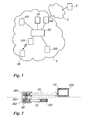
- Fig. 1 shows a packet-based WLAN 1 comprising a wireless phone 10, APs 111, 112, 113, a switch 13, a call server 12, and a gateway 14.
- the gateway 14 connects the WLAN 1 with another telephony network 2 comprising a subscribed telephone terminal 3.
- the wireless phone 10 may be any telephony device supporting standard IEEE 802.11 features, such as a VoWLAN telephone set or an appropriate softphone, e.g., a telephone software running on a desktop personal computer or a laptop, and is used by a first party who wishes to communicate via a telecommunications connection with a second party using the telephone terminal 3.
- a VoWLAN telephone set or an appropriate softphone, e.g., a telephone software running on a desktop personal computer or a laptop, and is used by a first party who wishes to communicate via a telecommunications connection with a second party using the telephone terminal 3.
- TDM Time Division Multiplexing
- Each of the APs 111 to 113 provides access to the WLAN 1 within a geographic cell served by the APs 111 to 113.
- the phone 10 may be connected via a wireless connection to one of the APs 111 to 113 of the WLAN 1 when it is located in the corresponding geographical cell covered by the one of the APs 111 to 113. For example, at the current position shown in Fig. 1, the phone 10 may be connected to the AP 111.
- Each of the APs 111 to 113 is connected via a distribution system of a backbone network to the central switch 13, forming a WLAN infrastructure.
- the central switch 13 provides switching functions in order to route an incoming or outgoing telephone call to an appropriate destination.
- the term "incoming call” refers to a call received by the wireless phone 10
- the term “outgoing call” refers to a call set up by the wireless phone 10.
- the call server 12 controls the set-up, performance and closing of telephony connections within the WLAN 1.
- PSTN Public Switched Telephone Network
- UMTS Universal Mobile Telecommunications System
- PABX Private Automatic Branch Exchange
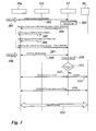
- Fig. 2 shows the communication channels between the phone 10, the call server 12 and the AP 111.
- the phone 10 comprises an application platform 101 and a WLAN infrastructure platform 102 compliant with the IEEE 802.11e standard.
- the call server comprises a control unit 121 providing the functionality with regard to the CAC.
- the basic idea of the invention is to use a bandwidth reservation mechanism as defined in the 802. 11e standard triggered by the call server 12 in order to implement CAC.
- the bandwidth reservation requesred by the phone 10 is under the control of the call server 12 using the application layer protocol.
- the call server 12 triggers the phone 10 to request a reservation of the required bandwidth at the AP 111.
- the communication between the call admission control unit 121 of the call server 12 and the application interface 101 of the phone 10 is conducted using the application layer protocol 21.
- the request is transmitted via channel 103 from the application platform of the phone 10 to the WLAN infrastructure platform 102 of the phone 10. Then the request is communicated from the phone 10 via the 802.11 e standard 22 to the AP 111.
- a priority matching the call priority e.g., emergency call / normal call, is associated with the requested bandwidth.
- the response to the request is transmitted via the 802.11e standard 22 from the AP 111 back to the phone 10, and the result of the bandwidth reservation performed by the AP 111 is reported via the application layer protocol 21 from the phone to the call server 12.
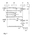
- Fig. 3 describes the sequence of messages and actions of an embodiment of the invention regarding the successful bandwidth reservation for an outgoing normal call.
- the process is conducted among a WLAN-compatible phone 10a of a calling party, e.g., a VoWLAN phone associated with the WLAN network 1, a WLAN infrastructure AP 111, a call server 12, and a phone 3b of a called party, e.g., a PSTN phone or a UMTS cell phone.
- a WLAN-compatible phone 10a of a calling party e.g., a VoWLAN phone associated with the WLAN network 1
- a WLAN infrastructure AP 111 e.g., a call server 12
- a phone 3b of a called party e.g., a PSTN phone or a UMTS cell phone.
- the calling party associated with the phone 10a wishes to call the called party using the phone 3b in a normal voice call.
- the calling party may hook off a handset of the phone 10a represented by, e.g., a hardphone, or initialise a software application of the phone 10a represented by, e.g., a softphone, or perform another appropriate user action 301 with regard to the phone 10a.
- the user action 301 at the phone 10a triggers a message 302 indicating the call initialisation event and sent from the phone 10a via a telephony stimuli protocol to the call server 12.
- a stimulus protocol is a type of protocol that is used to carry event notifications between end points. Such a protocol is used to control the operation of devices at each end of the link.
- a stimulus protocol is not sensitive to the system state.
- MiNET ® is a stimulus protocol that carries keystroke information from a telephone set to a call control server.
- the receipt of the message 302 at the call server 12 activates an application 303 of the call server 12, whereby the application 303 is associated with the request of an outgoing call.
- the application 303 triggers a message 304 sent from the call server 12 via the telephony stimuli protocol to the phone 10a.
- the message 304 is adapted to cause the phone 10a to request bandwidth corresponding to a normal voice call from the WLAN infrastructure.
- the bandwidth reservation mechanism uses the ADDTS request/Response frames as defined in the 802.11 e and in the WMM specifications from the Wi-Fi Alliance.
- admission control is triggered by the use of a TSPEC.
- a station here the phone 10a, specifies its traffic flow requirements (data rate, delay bounds, packet size, and others) and requests the QAP to create a TSPEC by sending the ADDTS management action frame.
- the QAP calculates the existing load based on the current set of issued TSPECs. Based on the current conditions, the QAP may accept or deny the new TSPEC request.
- the AP After receiving the ADDTS request 305, the AP analyses the current load situation. In the described embodiment, the load situation is low, so the AP 111 issues an ADDTS response 306 which indicates that the ADDTS request has been approved and correspondingly bandwidth has been allocated to a normal voice call originating from the phone 10a.
- the phone 10a receives the positive ADDTS response 306 and notifies the call server 12 by means of a message 307 sent via the telephony stimuli protocol that bandwidth has been allocated to the upcoming normal voice call.
- the calling party specifies address information associated with the telephone 3b of the called party.
- the calling party may dial a telephone number of the telephone 3b of the called party on a keypad of a hardphone, speak a telephone number into a microphone or use a computer mouse or a keyboard to input a telephone number of the called party.
- the telephone number of the called party is transmitted over a communication connection 309 via the telephony stimuli protocol from the phone 10a to the call server 12.
- the call server 12 After reception of the telephone number, the call server 12 performs an analysis 310 of the telephone number and performs a test 311 as to whether the telephone number is associated with a high priority call.
- the call server 12 may have access to a data base where high priority addresses are stored.
- the call server 12 accesses the data base and compares the received telephone number with the high priority addresses stored in the data base, e.g., telephone numbers of police, fire department, ambulance, road assistance, etc.
- the call server handles the call request with high or higher priority.
- the analysis and test result is that the telephone number received from the calling party's phone 10a is not an emergency number and that the corresponding call to be established is not an emergency call or high priority call, respectively.
- the call server 12 initiates the establishment and controlling of a normal voice call originating from the phone 10a by communication 312 with the phone 10a over the WLAN infrastructure via the telephony stimuli protocol.
- the call server 12 also performs a call set-up 313 to the called party's terminal 3b.
- RTP Real-Time Transport Protocol
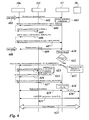
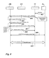
- Fig. 4 describes the sequence of messages and actions of an embodiment of the invention regarding the successful bandwidth reservation for an outgoing emergency call.
- the process is conducted among a WLAN-compatible calling party's phone 10a, e.g., a VoWLAN phone of the WLAN network 1, a WLAN infrastructure AP 111, a call server 12, and a called party's phone 3b, e.g., a PSTN phone.
- a WLAN-compatible calling party's phone 10a e.g., a VoWLAN phone of the WLAN network 1
- a WLAN infrastructure AP 111 e.g., a PSTN phone.
- the calling party associated with the phone 10a wishes to call the called party in an emergency voice call.
- the sequence steps 401 to 411 are identical to the steps 301 to 311 as described above and shown in Fig. 3.
- the analysis and test result is that the telephone number received from the calling party's phone 10a is indeed an emergency number and that the corresponding call to be established is to be handled as an emergency call or high priority call, respectively.
- the call server 12 requests the phone 10a to reserve priority bandwidth resources. This priority must be relayed by the phone 10a through the 802.11e TSPEC mechanism.
- a message 412 is sent from the call server 12 via the telephony stimuli protocol to the phone 10a.
- the message 412 is adapted to cause the phone 10a to request bandwidth corresponding to an emergency voice call from the WLAN infrastructure.
- the phone 10a triggered by the message 412, sends an ADDTS request 413 regarding the TSPEC corresponding to an emergency call to the AP 111.
- the priority setting for a voice priority call in the ADDTS request 413 is not specified.
- the concept to distinguish a voice priority call in an ADDTS request can be achieved through different ways such as, e.g., by adding a new field, using a specific access category, etc.
- the existent field "User Priority" with a specific value for "emergency call”, e.g., with the value 6 for normal calls and the value 7 for emergency calls can be used.
- the AP 111 After receiving the ADDTS request 413, the AP 111 analyses the current load situation. In the described embodiment, the load situation is low, so the AP 111 issues an ADDTS response 414 which indicates that the ADDTS request has been approved and correspondingly bandwidth has been allocated to an emergency voice call originating from the phone 10a.
- the phone 10a receives the positive ADDTS response 414 and notifies the call server 12 by means of a message 415 sent via the telephony stimuli protocol that bandwidth has been allocated to the upcoming emergency voice call.
- the receipt of the message 415 at the call server 12 activates an application 416 of the call server 12, whereby the application 416 is associated with the handling of an emergency call.
- the application 416 triggers the call server 12 to initiate the establishment and controlling of an emergency voice call originating from the phone 10a by communication 417 with the phone 10a over the WLAN infrastructure via the telephony stimuli protocol.
- the call server 12 also performs a call set-up 418 to the called party's terminal 3b.
- RTP Real-Time Transport Protocol
- the message 414 i.e., after the AP 111 acknowledges the reservation of bandwidth for the priority call
- the call-related traffic through the WLAN 1 is handled on an "emergency voice call" basis.
- the WLAN traffic is handled on a "best effort" basis.
- the same traffic handling priority pattern and changes apply in a corresponding manner also to the following embodiments.
- Fig. 5 describes the sequence of messages and actions of an embodiment of the invention regarding the failed bandwidth reservation for an outgoing normal call.
- the process is conducted among a WLAN-compatible calling party's phone 10a, e.g., a VoWLAN phone of the WLAN network 1, a WLAN infrastructure AP 111, a call server 12, and a called party's phone 3b, e.g., a PSTN phone.
- a WLAN-compatible calling party's phone 10a e.g., a VoWLAN phone of the WLAN network 1
- a WLAN infrastructure AP 111 e.g., a PSTN phone.
- the calling party associated with the phone 10a wishes to call the called party in a normal voice call.
- the sequence steps 501 to 505 are identical to the steps 301 to 305 as described above and shown in Fig. 3.
- the load situation is high so that the AP 111 issues an ADDTS response 506 which indicates that the ADDTS request 505 has been denied and no bandwidth has been allocated to the requested normal voice call originating from the phone 10a.
- the phone 10a receives the negative ADDTS response 506 and notifies the call server 12 by means of a message 507 sent via the telephony stimuli protocol that bandwidth can only be allocated on a best effort basis to the upcoming normal voice call.
- the calling party specifies the address of the called party.
- the telephone number of the called party is transmitted over a communication connection 509 via the telephony stimuli protocol from the phone 10a to the call server 12.
- the call server 12 After reception of the telephone number, the call server 12 performs an analysis 510 of the telephone number and performs a test 511 as to whether the telephone number is associated with a high priority call such as an emergency call to the police or the fire department.
- the analysis and test result is that the telephone number received from the calling party's phone 10a is not an emergency number and that the corresponding call to be established is not an emergency call or high priority call, respectively.
- the call server 12 sends a message 512 to the phone 10a over the WLAN infrastructure via the telephony stimuli protocol.
- the message 512 may cause the phone 10a to display "Network busy" on a screen of the phone 10a or may in another appropriate way notify the calling party about the high load of the WLAN network 1. Accordingly, the call server 12 aborts the outgoing call in step 513.
- Fig. 6 describes the sequence of messages and actions of an embodiment of the invention regarding the successful preemption of bandwidth resources for an outgoing emergency call.
- the process is conducted among a WLAN-compatible calling party's phone 10a, e.g., a VoWLAN phone of the WLAN network 1, a WLAN infrastructure AP 111, a call server 12, and a called party's phone 3b, e.g., a PSTN phone.
- the calling party associated with the phone 10a wishes to call the called party in an emergency voice call.
- the sequence steps 601 to 611 are identical to the steps 501 to 511 as described above and shown in Fig. 5. So far, the requested bandwidth has been denied because of the high network load and only a best-effort service can be delivered.
- the analysis result is positive, i.e., the requested call is an emergency call of higher priority with respect to already on-going calls on the network.
- an application 612 of the call server 12 issues a request 613 for the preemption of bandwidth for an emergency voice call.
- the message 613 is sent from the call server 12 via the telephony stimuli protocol to the phone 10.
- the message 613 is adapted to cause the phone 10a to request bandwidth corresponding to an emergency voice call from the WLAN infrastructure.
- the phone 10a triggered by the message 613, sends an ADDTS request 614 regarding the TSPEC corresponding to an emergency call to the AP 111.
- the request 614 is analysed with respect to the current load situation in the network 1.
- the AP 111 determines that the received bandwidth request 614 has to be handled with high priority since it refers to an emergency call. Since all available bandwidth of the network 1 is already allocated to other calls, bandwidth has to be preempted by the emergency call.
- the AP 111 starts an application 615 which releases one or more on-going calls of lower priority and reserves the released bandwidth for the upcoming emergency call of the calling party's phone 10a.
- the AP 111 tags the admitted traffic of the upcoming emergency call with its priority in order not to be preempted for new calls with a lower priority.
- the AP 111 always, i.e., independently of the priority of an intended call, tags bandwidth reserved for the call with the corresponding priority tag to prevent undue preemption.
- the AP 111 issues an ADDTS response 616 which indicates that the ADDTS request has been approved and correspondingly bandwidth has been preempted for an emergency voice call originating from the phone 10a.
- the phone 10a receives the positive ADDTS response 616 and notifies the call server 12 by means of a message 617 sent via the telephony stimuli protocol that bandwidth has been allocated to the upcoming emergency voice call.
- the receipt of the message 617 at the call server 12 activates an application 618 of the call server 12, whereby the application 618 is associated with the handling of an emergency call.
- the further steps 619 to 622 are identical to the steps 417 to 420 as described above and shown in Fig. 4
- Fig. 7 describes the sequence of messages and actions of an embodiment of the invention regarding the failed preemption of bandwidth resources for an outgoing emergency call.
- the process is conducted among a WLAN-compatible calling party's phone 10a, e.g., a VoWLAN phone of the WLAN network 1, a WLAN infrastructure AP 111, a call server 12, and a called party's phone 3b, e.g., a PSTN phone.
- the calling party associated with the phone 10a wishes to call the called party in an emergency voice call.
- the sequence steps 701 to 714 are identical to the steps 601 to 614 as described above and shown in Fig. 6. So far, the phone 10a sends a bandwidth request 714 for an emergency call to the AP 111.
- the request 714 is analysed with respect to the current load situation in the network 1.
- the AP 111 realises that the received bandwidth request 614 has to be handled with high priority since it refers to an emergency call. However, all calls handled by the AP 111 have the same or an even higher priority as the intended emergency call requested by the calling party's phone 10a. Since all available bandwidth of the network 1 is already allocated to other calls of equal rights, the bandwidth request 714 is denied by the AP 111.
- the AP 111 issues an ADDTS response 715 which indicates that the ADDTS request 714 has been denied and no bandwidth has been allocated to the requested emergency voice call originating from the phone 10a.
- the phone 10a receives the negative ADDTS response 715 and notifies the call server 12 by means of a message 716 sent via the telephony stimuli protocol that bandwidth can only be allocated on a best effort basis to the upcoming emergency voice call.
- an application 717 of the call server 12 is triggered which is related to the handling of an emergency failure.
- the call server 12 may send a message 718 to the phone 10a over the WLAN infrastructure via the telephony stimuli protocol.
- the message 718 may cause the phone 10a to display "Network busy" on a screen of the phone 10a or may in another appropriate way notify the calling party about the high load of the WLAN network 1, e.g., by means of a voice announcement to the calling party. Therefore, the calling party is prepared that the intended emergency call is not handled in the usual manner but that other measures have to be taken.
- the call server 12 may simply abort the call set-up in step 718.
- the call server 12 may set up the emergency call anyway independently of the achievable audio quality.
- the call server 12 may notify a local operator of the emergency call attempt with the calling party's telephone number and localisation information, e.g. the network address of the AP 111 the calling party's phone 10a is associated to. Then, the operator may try to assist the calling party.
- the call server 12 modifies the traffic specification towards the telephone 10a of the first party required for the high priority call, e.g., by changing the VoIP audio codec.
- the bandwidth resources required for the modified priority call may be reduced compared to the bandwidth resources required for the original priority call. Therefore, the bandwidth resources available in the network 1 may be sufficient to provide service to the modified priority call with reduced bandwidth requirements.
- the request procedure as described above and beginning with step 713 is repeated by sending, from the call server 12 to the telephone 10a of the first party, a request to reserve bandwidth for the modified high priority call at the access point 111.
- Fig. 8 describes the sequence of messages and actions of an embodiment of the invention regarding a successful bandwidth reservation for an incoming normal call.
- the process is conducted among a WLAN-compatible called party's phone 10b, e.g., a VoWLAN phone of the WLAN network 1, a WLAN infrastructure AP 111, a call server 12, and a calling party's phone 3a, e.g., a PSTN phone.
- a WLAN-compatible called party's phone 10b e.g., a VoWLAN phone of the WLAN network 1
- a WLAN infrastructure AP 111 e.g., a PSTN phone.
- a calling party's phone 3a e.g., a PSTN phone.
- the calling party using the phone 3a wishes to call the called party associated with the phone 10b in a normal voice call.
- the calling party initiates the call setup 802, e.g., by dialling the called party's telephone number assigned to the phone 10b.
- the call setup request 802 is sent to the call server 12.
- the receipt of the message 802 at the call server 12 activates an application 803 of the call server 12, whereby the application 803 is associated with a bandwidth request for an incoming call before alerting the called party's phone 10b, e.g., by ringing, displaying a message, vibrating, etc.
- the application 803 triggers a message 804 sent from the call server 12 via the telephony stimuli protocol to the phone 10b.
- the message 804 is adapted to cause the phone 10b to request bandwidth for an incoming normal voice call from the WLAN infrastructure.
- the phone 10b Once the message 804 is received at the phone 10b, the phone 10b, triggered by the message 803, sends an ADDTS request 805 regarding the TSPEC corresponding to a normal incoming call to the AP 111.
- the AP 111 After receiving the ADDTS request 805, the AP 111 analyses the current load situation. In the described embodiment, the load situation is low, so the AP 111 issues an ADDTS response 806 which indicates that the ADDTS request 805 has been approved and corresponding bandwidth has been allocated to the normal voice call waiting in-line at the call server 12.
- the phone 10b receives the positive ADDTS response 806 and notifies the call server 12 by means of a message 807 sent via the telephony stimuli protocol that bandwidth has been allocated to the upcoming normal voice call originating from the calling party's phone 3a.
- the call server 12 initiates the establishment and the control of a normal voice call originating from the phone 3a by communication 808 with the phone 10b over the WLAN infrastructure via the telephony stimuli protocol which notifies the called party through different ways in the VoWLAN phone (ringing, display of a message, vibrating, etc).
- an RTP transmission between the calling party's phone 3a and the called party's phone 10b is initialised by transmitting messages 809 comprising, e.g., audiocodecs for the adjustment of equivalent transmission parameters from the call server 12 to the calling party's phone 3a and the called party's phone 10b and by establishing an RTP communication connection.
- the call is conducted as voice RTP streams 810 of normal priority transmitted between the calling party's phone 3a and the called party's phone 10b.
- Fig. 9 describes the sequence of messages and actions of an embodiment of the invention regarding a failed bandwidth reservation for an incoming normal call.
- the process is conducted among a WLAN-compatible called party's phone 10b, e.g., a VoWLAN phone of the WLAN network 1, a WLAN infrastructure AP 111, a call server 12, and a calling party's phone 3a, e.g., a PSTN phone.
- a WLAN-compatible called party's phone 10b e.g., a VoWLAN phone of the WLAN network 1
- a WLAN infrastructure AP 111 e.g., a PSTN phone.
- a calling party's phone 3a e.g., a PSTN phone.
- the calling party using the phone 3a wishes to call the called party associated with the phone 10b in a normal voice call.
- the sequence steps 902 to 905 are identical to the steps 802 to 805 as described above and shown in Fig. 8. So far, the called party's phone 10b sends an ADDTS request 905 regarding the TSPEC corresponding to a normal incoming call to the AP 111.
- the AP 111 After receiving the ADDTS request 905, the AP 111 analyses the current load situation. In the described embodiment, the load situation is high, so the AP 111 issues an ADDTS response 906 which indicates that the ADDTS request has been denied and no bandwidth has been allocated to the normal voice call waiting in-line at the call server 12.
- the phone 10b receives the negative ADDTS response 906 and notifies the call server 12 by means of a message 907 sent via the telephony stimuli protocol that bandwidth can only be allocated on a best effort basis to the waiting normal voice call.
- an application 908 of the call server 12 issues a message 909 to the calling party's phone 3a.
- the message 909 may cause the phone 3a to display "Called party busy" on a screen of the phone 3a or may in another appropriate way notify the calling party about the high load of the WLAN network 1.
- the incoming waiting call is not forwarded to the called party's phone 10b and the connection between the call server 12 and the calling party's phone 3a is released.
- the called party's phone 10b is only alerted if the bandwidth required to establish the voice flow could be allocated. In the present embodiment, the called party's phone 10b is not alerted since the bandwidth required for the call could not be allocated.
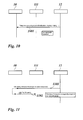
- Fig. 10 describes the sequence of messages and actions of an embodiment of the invention regarding a call server notification.
- the process is conducted among a WLAN-compatible stimuli phone 10, e.g., a VoWLAN phone of the WLAN network 1 and a call server 12.
- the stimuli phone 10 is totally under the control of the call server 12: actions on the phone 10 (user actions like key pressing) are reported to the call server 12 and the call server 12 sends commands to the phone 10 to modify the state of the phone 10 (display, audio mode).
- the application context is managed by the call server 12.
- the signaling traffic required to control the phone 10 is not very big and is not real time. So strictly speaking, bandwidth is required but is quite low and does not have to be reserved with traffic specifications and real time constraints as it is required for voice traffic.
- LED Light Emitting Diode
- This command 1001 can be sent to the phone 10 on a best effort basis.
- the message 1001 comprising a notification such as a display update or a ringing signal is transmitted via a telephony stimuli protocol from the call server 12 to the phone 10 on a best effort basis.
- Fig. 11 describes the sequence of messages and actions of an embodiment of the invention regarding a release of resources.
- the process is conducted among a WLAN-compatible phone 10, e.g., a VoWLAN phone of the WLAN network 1, a WLAN infrastructure AP 111, and a call server 12.
- the release of resources is explicitly required by the call server 12 by message 1101 and relayed by the phone through 802.11e messages 1102 to the WLAN infrastructure 111.
- the principle for CAC of the present invention is to get the bandwidth required for a call, incoming or outgoing, prior to alert the VoWLAN phone 10 for an incoming call or accept an outgoing call from the VoWLAN phone 10. If the required bandwidth is not available, the call server 12 may take the appropriate actions, e.g., reject a call, redirect an incoming call, log a congestion event, etc.
Landscapes
- Engineering & Computer Science (AREA)
- Computer Networks & Wireless Communication (AREA)
- Signal Processing (AREA)
- Multimedia (AREA)
- Quality & Reliability (AREA)
- Mobile Radio Communication Systems (AREA)
- Data Exchanges In Wide-Area Networks (AREA)
- Exchange Systems With Centralized Control (AREA)
- Telephonic Communication Services (AREA)
Abstract
Description
- The present invention relates to a method of controlling call admission in a WLAN, as well as a call server of the WLAN for providing call admission control (WLAN = Wireless Local Area Network).
- If a particular link in a packet based communication network is oversubscribed by influx of data traffic, a data congestion can be resolved by measures such as queueing, buffering, or packet drop. Data packets are simply held back until the data flow is smooth again. In the case of data drop, the target client simply requests a re-transmission of the missing packets. However, these measures cannot be applied in the case of real-time traffic, sensitive to both packet latency and packet loss, as the QoS would be severely decreased (QoS = Quality of Service).
- Today, the voice QoS deployed on WLANs is based on proprietary solutions, such as SVP allowing to support voice prioritisation, power saving, and CAC (SVP = SpectraLink® Voice Priority; CAC = Call Admission Control).
- SVP is the de facto standard for QoS on Wi-Fi networks (Wi-Fi = Wireless Fidelity). Adopted by the leading WLAN access point providers, SVP enables converged voice and data applications on a single wireless network infrastructure. SVP favours isochronous voice packets over asynchronous data packets when contending for the wireless medium and when transmitting packets onto the wired LAN (LAN = Local Area Network). SVP is an open specification that is compliant with the IEEE 802.11b standard and represents a cooperative solution between VoWLAN phones, WLAN infrastructure, and a dedicated equipment named SVP server (IEEE = Institute of Electrical and Electronics Engineers; VoWLAN = Voice over WLAN).
- CAC is a mechanism that prevents the presence of a new voice call from disrupting or degrading QoS for existing voice calls. In the case of delay-sensitive applications such as telephone calls or video-conferencing, it is a better solution to control and even deny network access to new calls under heavy load conditions. Otherwise, the newly admitted call would lead to a deteriorated transmission of all voice calls on the network.
- The reason for this general deterioration is that if packets exceeding a configured or allowable rate are received, these packets are simply tail-dropped from the queue. The queueing mechanism is not able to distinguish which IP packet belongs to which voice call. As the queueing policy cannot be limited to the newly admitted voice call, any packet exceeding a given arrival rate within a certain period of time will be dropped. Thus, all calls will experience packet loss, which is perceived as clips by the end users.
- In the SpectraLink architecture, CAC is managed between phones and the SVP server and is transparent for the WLAN infrastructure and the telephony call server. The main principles are as follows. The WLAN infrastructure, i.e. the Access Points (= AP), must implement a mechanism to prioritize voice traffic over data traffic. This is achieved by encapsulating the voice traffic in SRP PDUs exchanged between the WLAN telephone and the SVP server (SRP = SpectraLink Radio Protocol; PDU = Protocol Data Unit). The WLAN infrastructure uses the SRP protocol type to distinguish voice traffic from other traffics, and applies a higher priority to the voice traffic.
- Through a configuration menu in the SVP server, the administrator sets a parameter which defines the maximum of simultaneous calls per AP. This value is common for all APs. During the boot process of a WLAN phone, the phone retrieves the BSSID of the AP which it is associated with through IEEE 802.11 standard messages (BSSID = Basic Service Set Identifier). During an audio call establishment between the phone and the SVP server, the phone sends this AP BSSID via the SRP protocol to the SVP server.
- Therefore, the SVP server maintains a table including a list of APs associated with the on-going calls and can control the admission of calls to the APs. Each time the WLAN phone roams to a new AP, the table is updated via the same mechanism. When the maximum number of calls is reached on the AP the phone is currently associated with, the SVP server rejects any attempt to establish a new call over that particular AP. If the phone does not find any other available, i.e., not congested AP, a "network busy" message is displayed on the phone.
- Thus, CAC is a proprietary solution requiring also SVP-compliant APs for voice prioritisation and dedicated equipment such as SVP servers. Extra processes such as test runs are needed before deployment since the maximum of simultaneous calls per AP have to be calibrated first.
- Moreover, the current solution is based on static bandwidth reservation and traffic assumptions. It is not optimised for conditions when the traffic is different from the assumption. If real traffic is lower than assumed, the AP may accept more calls. On the other hand, if real traffic is higher than assumed, the AP may not be able to support the defined maximum number of calls. Voice traffic gets the priority over data traffic, thus data traffic would be limited but the maximum number of calls would be maintain. In addition, the maximum number of calls is global to all APs although traffic may be different at different locations.
- Further, the current solution does not support emergency calls, i.e., there is no prioritisation of emergency calls over normal calls.
- It is the object of the present invention to provide an improved call admission control.
- The object of the present invention is achieved by a method of providing admission control of a call between a telephone of a first party associated with an access point of a packet-based wireless local area network and a telephone of a second party, whereby the method comprises the steps of receiving, at a call server of the wireless local area network, at least one notification message regarding the intended call; sending, from the call server to the telephone of the first party, a request to reserve bandwidth for the call at the access point; sending, from the telephone of the first party to the access point, a bandwidth request for the call; processing, at the access point, the received bandwidth request in dependence on the current traffic load of the wireless local area network; sending a response to the bandwidth request from the access point to the telephone of the first party; transmitting, from the telephone of the first party to the call server, a notification message to notify the call server about the result of the bandwidth reservation; initiating, by the call server, the establishment of a call between the telephone of the first party and the telephone of the second party if the requested bandwidth has been allocated to the call. The object of the present invention is further achieved by a call server of a packet-based wireless local area network for providing admission control of a call between a telephone of a first party associated with an access point of the packet-based wireless local area network and a telephone of a second party, whereby the call server comprises a control unit adapted to receive at least one notification message regarding the intended call; send to the telephone of the first party a request to reserve bandwidth for the call at the access point; receive from the telephone of the first party a notification message to notify the call server about the result of the bandwidth reservation; and initiate the establishment of a call between the telephone of the first party and the telephone of the second party if the requested bandwidth has been allocated to the call.
- The invention concerns a method of providing call admission control in a WLAN comprising one or more access points and a call server. A WLAN telephone is associated with one of the one or more access points for wireless transmission of voice traffic between the telephone and the access points. The WLAN is also connected to one or more other telephony networks providing telephony service via a telephone terminal. If a user of the telephone wishes to establish a voice call to another party associated with the telephone terminal, the call admission according to the present invention relies on the IEEE 802.11e standard but is controlled by the call server.
- Usually, the calling party's dialing is reported in several messages. These user actions are analysed by the call server that is then able to decide if these actions are related to the establishment of a call (normal call or emergency call) requiring the allocation of bandwidth at the WLAN infrastructure or not. The user actions may be related to the activation of a service not requiring bandwidth allocation since no voice channel is required for this service (e.g. call forwarding activation).
- The present invention supports the CAC function on the basis of IEEE 802.11e standards, using features such as WMM and admission control (WMM = Wi-Fi Multimedia). This allows to have dynamic bandwidth management taking into account all kind of traffic, e.g., voice, data, etc. It solves the drawback of static bandwidth reservation with a SVP server.
- The solution uses the bandwidth reservation mechanism as defined by IEEE 802.11e (TSPEC = Traffic Specification) wherein the bandwidth reservation mechanism is triggered by the call server in order to implement CAC. With the present invention, a real bandwidth reservation is performed.
- Due to the ratification of the IEEE 802.11e standard, the proprietary solution based on SVP servers will no longer be necessary in the future for traffic prioritisation, power saving, and admission control. The present invention provides a succeeding solution to SVP.
- The invention provides an "infra agnostic" solution for CAC. There is no direct interaction between a call server and a WLAN infrastructure for bandwidth reservation mechanisms. The WLAN infrastructure and a phone using the WLAN infrastructure have only to support standard IEEE 802.11e features. The solution is therefore applicable to any WLAN infrastructure compliant with IEEE 802.11e standards, in particular to any VoWLAN stimuli phone enabled to implement the dialog with the call server to receive bandwidth reservation requests and return the result of the actual bandwidth reservation at the WLAN infrastructure.
- The present solution is adapted to support priority call. Priority calls, e.g., emergency calls, preempt WLAN resources already allocated to lower priority traffic in case of WLAN congestion. It is even possible to define more priority levels for voice traffic, e.g., providing a connection to Multi-Level Precedence and Preemption (= MLPP).
- Moreover, the invention provides a flexible bandwidth reservation. It is possible to handle variable traffic load levels where traffic may be different at different locations, i.e., APs. This means that the maximum number of calls that can be supported by each AP can be different.
- Further advantages are achieved by the embodiments of the invention indicated by the dependent claims.
- According to a preferred embodiment of the invention, when receiving a new bandwidth reservation request and based on the priority of the call associated with the bandwidth reservation request, the AP should preempt resources allocated to lower priority traffic in case of congestion. When a party using a WLAN-related communication terminal, e.g., a VoWLAN-phone, dials a priority number such as an emergency number associated with the police, the calling party may expect the WLAN to process the urgent call with a higher priority than a normal subscriber conversation. The address information input by the calling party is transmitted to the call server.
- The call server determines by analysis of the address information associated to a call whether a specific priority has to be assigned to the call, e.g., by analysing the telephone number dialled by the calling party. For example, the call server may refer to a data base comprising all telephone numbers relating to calls which have to be handled with a higher priority than usual telephone calls. In the case of a higher priority call request, the call server triggers the telephone of the calling party to request bandwidth with a priority as defined by the call server from the AP serving the calling party's telephone. When the AP receives the request, the AP checks the current traffic load situation of the traffic handled by the AP.
- It is possible that the current load situation is low, i.e., that enough bandwidth is freely available. Then the bandwidth is readily allocated to the priority call. The allocated bandwidth must be tagged at the AP with the given priority in order not to be preempted for subsequent traffics with lower priority.
- Alternatively, it is also possible that all bandwidth has been already allocated to previously requested calls. Then either it is possible to preempt bandwidth for the upcoming priority call from on-going calls of lower priority. However, if all previously requested calls are of the same or even higher priority, bandwidth cannot be preempted for the upcoming priority call and the upcoming priority call cannot be currently established over the current AP. Preferably, it is only in case bandwidth has been allocated to the upcoming priority call that the call is established by means of the call server. In any case, the result of a failed bandwidth reservation at the WLAN infrastructure must be reported to the call server that may decide of alternate actions.
- According to another preferred embodiment of the invention, the establishment of a high priority call between a WLAN telephone of a first party and a telephone of a second party is performed even if no bandwidth is currently available and allocatable to the high priority call. It may be considered more important to provide a communication channel in the case of an emergency than to respect any QoS requirements. Thus, the priority call may be established by the call server at the risk of bad audio quality.
- Preferably, the call server modifies the traffic specifications of a call to be set up if a call-related bandwidth request sent to the AP is denied. The call server may, e.g., change the VolP audio codec associated with the call. Consequently, the bandwidth resources required for the modified priority call may be lower than the bandwidth resources required for the original priority call. Therefore, in contrast to the original bandwidth request, the bandwidth resources currently available in the network may now be sufficient to provide service to the modified priority call with its reduced bandwidth requirements. After the modification is completed, the call server re-sends a request to reserve bandwidth for the modified priority call at the access point to the telephone of the first party.
- According to another preferred embodiment of the invention, the call server may notify a local operator of a failed emergency call attempt of a party using a WLAN telephone if bandwidth allocation to a high priority call has been denied by the WLAN infrastructure, e.g., an AP. The notification provided by the call server to the operator may include address information of the telephone of the party, e.g., the telephone number associated with the telephone of the party. The notification message may also comprise a localisation information of the telephone of the party, e.g., an identifier or an address of an AP providing the telephone of the calling party with a connection to the WLAN.
- In a preferred embodiment, the WLAN telephone of a communication party of an on-going call notifies the call server of any modification of the bandwidth resources allocated to the on-going call. For example, the on-going call is of normal priority. When a higher priority call is to be established, the call server may initiate the preemption for the high priority call from the AP. Then the AP may decide that the on-going normal call should be aborted in order to release the corresponding bandwidth resources for the high priority call.
- Before a call is aborted, the call server must explicitely confirm and require the release of resources. Thus, the call server sends to the telephone of the party whose call is to be aborted, a request to release bandwidth resources allocated to the call at the access point. The telephone of the party whose call is to be aborted sends to the access point a bandwidth release request for the call. Usually, the access point will release the bandwidth resources allocated to the call and the call server will abort the call because the QoS can no longer be maintained.
- When performing a communication via a WLAN, e.g., a VoWLAN telephone call, the user of the VoWLAN telephone may move within the coverage area of the WLAN. Therefore, the VoWLAN telephone may reach the border of the coverage area of a first AP and enter the coverage area of a second AP.
- Consequently, a hand-over of the communication connection has to be performed from the first to the second AP during the on-going call with respective bandwidth requirements.
- According to another preferred embodiment of the invention, the WLAN phone must also take into account the required bandwidth for the selection of a new AP during the hand-over in order to maintain the bandwidth required for the on-going calls and the agreed upon QoS. For example, the phone should not switch to an AP with a better RSSI but unable to provide the required bandwidth (RSSI = Received Signal Strength Indicator). This can be achieved by the phone by taking into account the QBSS load information as defined in the IEEE 802.11 standards in the AP selection algorithm (QBSS = QoS Basic Service Set). The QBSS is enabled to advertise channel load information in the beacon and probe response frames. Some IP phones use QBSS elements to determine which access point to associate to, based on the traffic load.
- During hand-over the VoWLAN telephone should request the same bandwidth from the new AP than the bandwidth available on the old AP in order to maintain the same level of QoS. In this case the bandwidth reservation request is not triggered by the Call Server. The phone must notify the Call Server if the bandwidth could not be obtained at the new AP. If for any reason this bandwidth could not be obtained from the new AP, the call server must be notified that the bandwidth resources allocated to the on-going call have been modified in order to take appropriate actions (i.e., release the call because the QoS cannot be maintained).
- Preferably, the communication between the telephone associated with the WLAN and the call server is done using an application layer protocol and the communication between the telephone associated with the WLAN and the AP serving the telephone is done using the IEEE 802.11e standard mechanism. Preferably, the application layer protocol is a telephone stimuli protocol. This protocol must be reliable, i.e., comprise a message acknowledgement.
- Preferably, the control unit of the call server is enabled to send a notification message to the telephone of the first party without the need of prior bandwidth reservation. Thus, no bandwidth is required for notifications such as display messages and ringing within the wireless local area network using a telephony stimuli protocol, when not related to a call.
- According to another preferred embodiment of the invention, the call server provides a feedback means for the calling party and called party, respectively, of a call via a WLAN network. The control unit of the call server sends a notification message to the telephone of the first party and/or the telephone of the second party in case of a call failure. The notification message may comprise a display message to be displayed at a terminal display of the telephones or a voice announcement to be played via the loudspeakers of the telephones. In case of call failure because the required bandwidth is not available, the notification to the first party may be different to the notification to the second party phone. On the first party's phone a voice announcement cannot be played since this is a voice flow and the bandwidth required to send this flow is not available. This restriction is not relevant for the second party phone.
- These as well as further features and advantages of the invention will be better appreciated by reading the following detailed description of presently preferred exemplary embodiments taken in conjunction with accompanying drawings of which:
- Fig. 1
- is a block diagram of a WLAN network according to an embodiment of the invention.
- Fig. 2
- is a block diagram showing the communication platforms used for the bandwidth reservation according to another embodiment of the invention.
- Fig. 3
- is a message sequence chart of an embodiment of the invention regarding successful bandwidth reservation for an outgoing normal call.
- Fig. 4
- is a message sequence chart of an embodiment of the invention regarding successful bandwidth reservation for an outgoing emergency call.
- Fig. 5
- is a message sequence chart of an embodiment of the invention regarding failed bandwidth reservation for an outgoing normal call.
- Fig. 6
- is a message sequence chart of an embodiment of the invention regarding successful preemption for an outgoing emergency call.
- Fig. 7
- is a message sequence chart of an embodiment of the invention regarding failed preemption for an outgoing emergency call.
- Fig. 8
- is a message sequence chart of an embodiment of the invention regarding sucessful bandwidth reservation for an incoming call.
- Fig. 9
- is a message sequence chart of an embodiment of the invention regarding failed bandwidth reservation for an incoming call.
- Fig. 10
- is a message sequence chart of an embodiment of the invention regarding call server notification.
- Fig. 11
- is a message sequence chart of an embodiment of the invention regarding a release of resources.
- Fig. 1 shows a packet-based
WLAN 1 comprising awireless phone 10,APs switch 13, acall server 12, and agateway 14. Thegateway 14 connects theWLAN 1 with another telephony network 2 comprising a subscribedtelephone terminal 3. - The
wireless phone 10 may be any telephony device supporting standard IEEE 802.11 features, such as a VoWLAN telephone set or an appropriate softphone, e.g., a telephone software running on a desktop personal computer or a laptop, and is used by a first party who wishes to communicate via a telecommunications connection with a second party using thetelephone terminal 3. - The
telephone terminal 3 of the second party may be any kind of phone, an IP phone or a TDM phone behind a VolP gateway (TDM = Time Division Multiplexing). It may be connected on the sameLocal Area Network 1 than the first party'sphone 10 or on another network 2. Thetelephone terminal 3 may even be another VoWLAN phone. - Each of the
APs 111 to 113 provides access to theWLAN 1 within a geographic cell served by theAPs 111 to 113. Thephone 10 may be connected via a wireless connection to one of theAPs 111 to 113 of theWLAN 1 when it is located in the corresponding geographical cell covered by the one of theAPs 111 to 113. For example, at the current position shown in Fig. 1, thephone 10 may be connected to theAP 111. Each of theAPs 111 to 113 is connected via a distribution system of a backbone network to thecentral switch 13, forming a WLAN infrastructure. - The
central switch 13 provides switching functions in order to route an incoming or outgoing telephone call to an appropriate destination. In the sense of this description, the term "incoming call" refers to a call received by thewireless phone 10, while the term "outgoing call" refers to a call set up by thewireless phone 10. Thecall server 12 controls the set-up, performance and closing of telephony connections within theWLAN 1. TheWLAN 1 is connected via agateway 14 to another telephony network, e.g., a conventional PSTN, a mobile UMTS network or a wireline PABX (PSTN = Public Switched Telephone Network; UMTS = Universal Mobile Telecommunications System; PABX = Private Automatic Branch Exchange). - Fig. 2 shows the communication channels between the
phone 10, thecall server 12 and theAP 111. Thephone 10 comprises anapplication platform 101 and aWLAN infrastructure platform 102 compliant with the IEEE 802.11e standard. The call server comprises acontrol unit 121 providing the functionality with regard to the CAC. - The basic idea of the invention is to use a bandwidth reservation mechanism as defined in the 802. 11e standard triggered by the
call server 12 in order to implement CAC. The bandwidth reservation mechanism as defined in the 802.11 e standard is requested by the QoS enabled station (= QSTA), here thephone 10, from the QoS enabled AP, here theAP 111. - The bandwidth reservation requesred by the
phone 10 is under the control of thecall server 12 using the application layer protocol. When bandwidth of theWLAN 1 is required for a voice call coming into theWLAN 1 and destined to thephone 10 or for a voice call going out of theWLAN 1 and originating from thephone 10, thecall server 12 triggers thephone 10 to request a reservation of the required bandwidth at theAP 111. The communication between the calladmission control unit 121 of thecall server 12 and theapplication interface 101 of thephone 10 is conducted using theapplication layer protocol 21. - The request is transmitted via
channel 103 from the application platform of thephone 10 to theWLAN infrastructure platform 102 of thephone 10. Then the request is communicated from thephone 10 via the 802.11 e standard 22 to theAP 111. A priority matching the call priority, e.g., emergency call / normal call, is associated with the requested bandwidth. - The response to the request is transmitted via the 802.11e standard 22 from the
AP 111 back to thephone 10, and the result of the bandwidth reservation performed by theAP 111 is reported via theapplication layer protocol 21 from the phone to thecall server 12. - Fig. 3 describes the sequence of messages and actions of an embodiment of the invention regarding the successful bandwidth reservation for an outgoing normal call. The process is conducted among a WLAN-
compatible phone 10a of a calling party, e.g., a VoWLAN phone associated with theWLAN network 1, aWLAN infrastructure AP 111, acall server 12, and aphone 3b of a called party, e.g., a PSTN phone or a UMTS cell phone. - The calling party associated with the
phone 10a wishes to call the called party using thephone 3b in a normal voice call. To initiate the call, the calling party may hook off a handset of thephone 10a represented by, e.g., a hardphone, or initialise a software application of thephone 10a represented by, e.g., a softphone, or perform anotherappropriate user action 301 with regard to thephone 10a. Theuser action 301 at thephone 10a triggers amessage 302 indicating the call initialisation event and sent from thephone 10a via a telephony stimuli protocol to thecall server 12. In telephony, a stimulus protocol is a type of protocol that is used to carry event notifications between end points. Such a protocol is used to control the operation of devices at each end of the link. However a stimulus protocol is not sensitive to the system state. For example, MiNET® is a stimulus protocol that carries keystroke information from a telephone set to a call control server. - The receipt of the
message 302 at thecall server 12 activates anapplication 303 of thecall server 12, whereby theapplication 303 is associated with the request of an outgoing call. - The
application 303 triggers amessage 304 sent from thecall server 12 via the telephony stimuli protocol to thephone 10a. Themessage 304 is adapted to cause thephone 10a to request bandwidth corresponding to a normal voice call from the WLAN infrastructure. Once themessage 304 is received at thephone 10a, thephone 10a, triggered by themessage 304, sends anADDTS request 305 regarding the TSPEC corresponding to a normal call to the AP 111 (ADDTS = add TSPEC). - The bandwidth reservation mechanism uses the ADDTS request/Response frames as defined in the 802.11 e and in the WMM specifications from the Wi-Fi Alliance. According to the 802.11 standard, admission control is triggered by the use of a TSPEC. A station, here the
phone 10a, specifies its traffic flow requirements (data rate, delay bounds, packet size, and others) and requests the QAP to create a TSPEC by sending the ADDTS management action frame. The QAP calculates the existing load based on the current set of issued TSPECs. Based on the current conditions, the QAP may accept or deny the new TSPEC request. - After receiving the
ADDTS request 305, the AP analyses the current load situation. In the described embodiment, the load situation is low, so theAP 111 issues anADDTS response 306 which indicates that the ADDTS request has been approved and correspondingly bandwidth has been allocated to a normal voice call originating from thephone 10a. Thephone 10a receives thepositive ADDTS response 306 and notifies thecall server 12 by means of amessage 307 sent via the telephony stimuli protocol that bandwidth has been allocated to the upcoming normal voice call. - As a
next step 308, the calling party specifies address information associated with thetelephone 3b of the called party. The calling party may dial a telephone number of thetelephone 3b of the called party on a keypad of a hardphone, speak a telephone number into a microphone or use a computer mouse or a keyboard to input a telephone number of the called party. The telephone number of the called party is transmitted over acommunication connection 309 via the telephony stimuli protocol from thephone 10a to thecall server 12. After reception of the telephone number, thecall server 12 performs ananalysis 310 of the telephone number and performs atest 311 as to whether the telephone number is associated with a high priority call. - For the mentioned
emergency test 311, thecall server 12 may have access to a data base where high priority addresses are stored. When analysing and checking the received telephone number, thecall server 12 accesses the data base and compares the received telephone number with the high priority addresses stored in the data base, e.g., telephone numbers of police, fire department, ambulance, road assistance, etc. When the received telephone number exists as an entry in the data base, the call server handles the call request with high or higher priority. - In the present embodiment, the analysis and test result is that the telephone number received from the calling party's
phone 10a is not an emergency number and that the corresponding call to be established is not an emergency call or high priority call, respectively. - Accordingly, the
call server 12 initiates the establishment and controlling of a normal voice call originating from thephone 10a bycommunication 312 with thephone 10a over the WLAN infrastructure via the telephony stimuli protocol. Thecall server 12 also performs a call set-up 313 to the called party's terminal 3b. In the next step, an RTP transmission between the calling party'sphone 10 and the called party'sphone 3b is initialised by transmittingmessages 314 comprising, e.g., audiocodecs for the adjustment of equivalent transmission parameters from thecall server 12 to the calling party'sphone 10a and the called party'sphone 3b and by establishing an RTP communication connection (RTP = Real-Time Transport Protocol). Finally, the call is conducted as voice RTP streams 315 of normal priority transmitted between the calling party'sphone 10a and the called party'sphone 3b. - In the infrastructure of the
WLAN network 1, all call-related traffic through theWLAN 1 after themessage 305, i.e., after theAP 111 receives the request of the normal voice call, is handled on a "normal voice" basis. Before themessage 305, traffic is handled on a "best effort" basis. The default QoS afforded to a general packet-based communications link is termed "best effort" where network elements forward packets on a first come-first served basis without any preference. - Fig. 4 describes the sequence of messages and actions of an embodiment of the invention regarding the successful bandwidth reservation for an outgoing emergency call. As in the embodiment illustrated in Fig. 3, the process is conducted among a WLAN-compatible calling party's
phone 10a, e.g., a VoWLAN phone of theWLAN network 1, aWLAN infrastructure AP 111, acall server 12, and a called party'sphone 3b, e.g., a PSTN phone. - The calling party associated with the
phone 10a wishes to call the called party in an emergency voice call. The sequence steps 401 to 411 are identical to thesteps 301 to 311 as described above and shown in Fig. 3. - In the present embodiment, the analysis and test result is that the telephone number received from the calling party's
phone 10a is indeed an emergency number and that the corresponding call to be established is to be handled as an emergency call or high priority call, respectively. - For priority calls, the
call server 12 requests thephone 10a to reserve priority bandwidth resources. This priority must be relayed by thephone 10a through the 802.11e TSPEC mechanism. - Accordingly, triggered by the positive emergency test result, a
message 412 is sent from thecall server 12 via the telephony stimuli protocol to thephone 10a. Themessage 412 is adapted to cause thephone 10a to request bandwidth corresponding to an emergency voice call from the WLAN infrastructure. Once themessage 412 is received at thephone 10a, thephone 10a, triggered by themessage 412, sends anADDTS request 413 regarding the TSPEC corresponding to an emergency call to theAP 111. - The priority setting for a voice priority call in the
ADDTS request 413 is not specified. For example, the concept to distinguish a voice priority call in an ADDTS request can be achieved through different ways such as, e.g., by adding a new field, using a specific access category, etc. Also, the existent field "User Priority" with a specific value for "emergency call", e.g., with the value 6 for normal calls and the value 7 for emergency calls, can be used. - After receiving the
ADDTS request 413, theAP 111 analyses the current load situation. In the described embodiment, the load situation is low, so theAP 111 issues anADDTS response 414 which indicates that the ADDTS request has been approved and correspondingly bandwidth has been allocated to an emergency voice call originating from thephone 10a. Thephone 10a receives thepositive ADDTS response 414 and notifies thecall server 12 by means of amessage 415 sent via the telephony stimuli protocol that bandwidth has been allocated to the upcoming emergency voice call. - The receipt of the
message 415 at thecall server 12 activates anapplication 416 of thecall server 12, whereby theapplication 416 is associated with the handling of an emergency call. Theapplication 416 triggers thecall server 12 to initiate the establishment and controlling of an emergency voice call originating from thephone 10a bycommunication 417 with thephone 10a over the WLAN infrastructure via the telephony stimuli protocol. - The
call server 12 also performs a call set-up 418 to the called party's terminal 3b. In the next step, an RTP transmission between the calling party'sphone 10a and the called party'sphone 3b is initialised by transmittingmessages 419 comprising, e.g., audiocodecs for the adjustment of equivalent transmission parameters from thecall server 12 to the calling party'sphone 10a and the called party'sphone 3b and by establishing an RTP communication connection (RTP = Real-Time Transport Protocol). Finally, the call is conducted as voice RTP streams 315 of high priority/emergency status transmitted between the calling party'sphone 10a and the called party'sphone 3b. - In the infrastructure of the
WLAN network 1, the call-related traffic through theWLAN 1 after themessage 405, i.e., after theAP 111 receives the request of the normal voice call, and before themessage 414 is handled on a "normal voice call" basis. After themessage 414, i.e., after theAP 111 acknowledges the reservation of bandwidth for the priority call, the call-related traffic through theWLAN 1 is handled on an "emergency voice call" basis. Before themessage 405, the WLAN traffic is handled on a "best effort" basis. The same traffic handling priority pattern and changes apply in a corresponding manner also to the following embodiments. - Fig. 5 describes the sequence of messages and actions of an embodiment of the invention regarding the failed bandwidth reservation for an outgoing normal call. As in the embodiment illustrated in Fig. 3, the process is conducted among a WLAN-compatible calling party's
phone 10a, e.g., a VoWLAN phone of theWLAN network 1, aWLAN infrastructure AP 111, acall server 12, and a called party'sphone 3b, e.g., a PSTN phone. - The calling party associated with the
phone 10a wishes to call the called party in a normal voice call. The sequence steps 501 to 505 are identical to thesteps 301 to 305 as described above and shown in Fig. 3. - In the described embodiment, the load situation is high so that the
AP 111 issues anADDTS response 506 which indicates that theADDTS request 505 has been denied and no bandwidth has been allocated to the requested normal voice call originating from thephone 10a. Thephone 10a receives thenegative ADDTS response 506 and notifies thecall server 12 by means of amessage 507 sent via the telephony stimuli protocol that bandwidth can only be allocated on a best effort basis to the upcoming normal voice call. - Best effort means that the network controlling facilities cannot give any QoS guaranties for the availability of the transmission resources, the delay and transmission rate of packets. This may be sufficient and cheap for most of the classical network services like FTP, HTTP or email (FTP = File Transfer Protocol; HTTP = Hyper Text Transfer Protocol). VolP applications, however, require higher QoS standards.
- As a
next step 508, the calling party specifies the address of the called party. The telephone number of the called party is transmitted over acommunication connection 509 via the telephony stimuli protocol from thephone 10a to thecall server 12. After reception of the telephone number, thecall server 12 performs ananalysis 510 of the telephone number and performs atest 511 as to whether the telephone number is associated with a high priority call such as an emergency call to the police or the fire department. - In the present embodiment, the analysis and test result is that the telephone number received from the calling party's
phone 10a is not an emergency number and that the corresponding call to be established is not an emergency call or high priority call, respectively. - Acordingly, the
call server 12 sends amessage 512 to thephone 10a over the WLAN infrastructure via the telephony stimuli protocol. Themessage 512 may cause thephone 10a to display "Network busy" on a screen of thephone 10a or may in another appropriate way notify the calling party about the high load of theWLAN network 1. Accordingly, thecall server 12 aborts the outgoing call instep 513. - Fig. 6 describes the sequence of messages and actions of an embodiment of the invention regarding the successful preemption of bandwidth resources for an outgoing emergency call. As in the embodiment illustrated in Fig. 5, the process is conducted among a WLAN-compatible calling party's
phone 10a, e.g., a VoWLAN phone of theWLAN network 1, aWLAN infrastructure AP 111, acall server 12, and a called party'sphone 3b, e.g., a PSTN phone. - The calling party associated with the
phone 10a wishes to call the called party in an emergency voice call. The sequence steps 601 to 611 are identical to thesteps 501 to 511 as described above and shown in Fig. 5. So far, the requested bandwidth has been denied because of the high network load and only a best-effort service can be delivered. - When the dialled telephone number is tested in
step 611 as to whether the telephone number is associated with a high priority call, the analysis result is positive, i.e., the requested call is an emergency call of higher priority with respect to already on-going calls on the network. Initiated by the emergency character of the requested call, an application 612 of thecall server 12 issues arequest 613 for the preemption of bandwidth for an emergency voice call. - The
message 613 is sent from thecall server 12 via the telephony stimuli protocol to thephone 10. Themessage 613 is adapted to cause thephone 10a to request bandwidth corresponding to an emergency voice call from the WLAN infrastructure. Once themessage 613 is received at thephone 10a, thephone 10a, triggered by themessage 613, sends anADDTS request 614 regarding the TSPEC corresponding to an emergency call to theAP 111. - At the
AP 111, therequest 614 is analysed with respect to the current load situation in thenetwork 1. TheAP 111 determines that the receivedbandwidth request 614 has to be handled with high priority since it refers to an emergency call. Since all available bandwidth of thenetwork 1 is already allocated to other calls, bandwidth has to be preempted by the emergency call. TheAP 111 starts anapplication 615 which releases one or more on-going calls of lower priority and reserves the released bandwidth for the upcoming emergency call of the calling party'sphone 10a. - Preferably, the
AP 111 tags the admitted traffic of the upcoming emergency call with its priority in order not to be preempted for new calls with a lower priority. In general, in a preferred embodiment, theAP 111 always, i.e., independently of the priority of an intended call, tags bandwidth reserved for the call with the corresponding priority tag to prevent undue preemption. - The
AP 111 issues anADDTS response 616 which indicates that the ADDTS request has been approved and correspondingly bandwidth has been preempted for an emergency voice call originating from thephone 10a. Thephone 10a receives thepositive ADDTS response 616 and notifies thecall server 12 by means of amessage 617 sent via the telephony stimuli protocol that bandwidth has been allocated to the upcoming emergency voice call. - The receipt of the
message 617 at thecall server 12 activates anapplication 618 of thecall server 12, whereby theapplication 618 is associated with the handling of an emergency call. Thefurther steps 619 to 622 are identical to thesteps 417 to 420 as described above and shown in Fig. 4 - Fig. 7 describes the sequence of messages and actions of an embodiment of the invention regarding the failed preemption of bandwidth resources for an outgoing emergency call. As in the embodiment illustrated in Fig. 6, the process is conducted among a WLAN-compatible calling party's
phone 10a, e.g., a VoWLAN phone of theWLAN network 1, aWLAN infrastructure AP 111, acall server 12, and a called party'sphone 3b, e.g., a PSTN phone. - The calling party associated with the
phone 10a wishes to call the called party in an emergency voice call. The sequence steps 701 to 714 are identical to thesteps 601 to 614 as described above and shown in Fig. 6. So far, thephone 10a sends abandwidth request 714 for an emergency call to theAP 111. - At the
AP 111, therequest 714 is analysed with respect to the current load situation in thenetwork 1. TheAP 111 realises that the receivedbandwidth request 614 has to be handled with high priority since it refers to an emergency call. However, all calls handled by theAP 111 have the same or an even higher priority as the intended emergency call requested by the calling party'sphone 10a. Since all available bandwidth of thenetwork 1 is already allocated to other calls of equal rights, thebandwidth request 714 is denied by theAP 111. - The
AP 111 issues anADDTS response 715 which indicates that theADDTS request 714 has been denied and no bandwidth has been allocated to the requested emergency voice call originating from thephone 10a. Thephone 10a receives thenegative ADDTS response 715 and notifies thecall server 12 by means of amessage 716 sent via the telephony stimuli protocol that bandwidth can only be allocated on a best effort basis to the upcoming emergency voice call. - After reception of the
negative message 716, anapplication 717 of thecall server 12 is triggered which is related to the handling of an emergency failure. - As a first reaction to the denial of bandwidth, the
call server 12 may send amessage 718 to thephone 10a over the WLAN infrastructure via the telephony stimuli protocol. Themessage 718 may cause thephone 10a to display "Network busy" on a screen of thephone 10a or may in another appropriate way notify the calling party about the high load of theWLAN network 1, e.g., by means of a voice announcement to the calling party. Therefore, the calling party is prepared that the intended emergency call is not handled in the usual manner but that other measures have to be taken. - As a first alternative, the
call server 12 may simply abort the call set-up instep 718. In a preferred embodiment, instead of thecall server 12 aborting the outgoing emergency call, thecall server 12 may set up the emergency call anyway independently of the achievable audio quality. In still another embodiment, thecall server 12 may notify a local operator of the emergency call attempt with the calling party's telephone number and localisation information, e.g. the network address of theAP 111 the calling party'sphone 10a is associated to. Then, the operator may try to assist the calling party. - In another embodiment, the
call server 12 modifies the traffic specification towards thetelephone 10a of the first party required for the high priority call, e.g., by changing the VoIP audio codec. By doing this, the bandwidth resources required for the modified priority call may be reduced compared to the bandwidth resources required for the original priority call. Therefore, the bandwidth resources available in thenetwork 1 may be sufficient to provide service to the modified priority call with reduced bandwidth requirements. After the modification is completed, the request procedure as described above and beginning withstep 713 is repeated by sending, from thecall server 12 to thetelephone 10a of the first party, a request to reserve bandwidth for the modified high priority call at theaccess point 111. - Fig. 8 describes the sequence of messages and actions of an embodiment of the invention regarding a successful bandwidth reservation for an incoming normal call. The process is conducted among a WLAN-compatible called party's
phone 10b, e.g., a VoWLAN phone of theWLAN network 1, aWLAN infrastructure AP 111, acall server 12, and a calling party'sphone 3a, e.g., a PSTN phone. - The calling party using the
phone 3a wishes to call the called party associated with thephone 10b in a normal voice call. The calling party initiates thecall setup 802, e.g., by dialling the called party's telephone number assigned to thephone 10b. Thecall setup request 802 is sent to thecall server 12. The receipt of themessage 802 at thecall server 12 activates an application 803 of thecall server 12, whereby the application 803 is associated with a bandwidth request for an incoming call before alerting the called party'sphone 10b, e.g., by ringing, displaying a message, vibrating, etc. - The application 803 triggers a
message 804 sent from thecall server 12 via the telephony stimuli protocol to thephone 10b. Themessage 804 is adapted to cause thephone 10b to request bandwidth for an incoming normal voice call from the WLAN infrastructure. Once themessage 804 is received at thephone 10b, thephone 10b, triggered by the message 803, sends anADDTS request 805 regarding the TSPEC corresponding to a normal incoming call to theAP 111. - After receiving the
ADDTS request 805, theAP 111 analyses the current load situation. In the described embodiment, the load situation is low, so theAP 111 issues anADDTS response 806 which indicates that theADDTS request 805 has been approved and corresponding bandwidth has been allocated to the normal voice call waiting in-line at thecall server 12. Thephone 10b receives thepositive ADDTS response 806 and notifies thecall server 12 by means of amessage 807 sent via the telephony stimuli protocol that bandwidth has been allocated to the upcoming normal voice call originating from the calling party'sphone 3a. - As a
next step 808, thecall server 12 initiates the establishment and the control of a normal voice call originating from thephone 3a bycommunication 808 with thephone 10b over the WLAN infrastructure via the telephony stimuli protocol which notifies the called party through different ways in the VoWLAN phone (ringing, display of a message, vibrating, etc). In the next step, an RTP transmission between the calling party'sphone 3a and the called party'sphone 10b is initialised by transmittingmessages 809 comprising, e.g., audiocodecs for the adjustment of equivalent transmission parameters from thecall server 12 to the calling party'sphone 3a and the called party'sphone 10b and by establishing an RTP communication connection. Finally, the call is conducted as voice RTP streams 810 of normal priority transmitted between the calling party'sphone 3a and the called party'sphone 10b. - Fig. 9 describes the sequence of messages and actions of an embodiment of the invention regarding a failed bandwidth reservation for an incoming normal call. The process is conducted among a WLAN-compatible called party's
phone 10b, e.g., a VoWLAN phone of theWLAN network 1, aWLAN infrastructure AP 111, acall server 12, and a calling party'sphone 3a, e.g., a PSTN phone. - The calling party using the
phone 3a wishes to call the called party associated with thephone 10b in a normal voice call. The sequence steps 902 to 905 are identical to thesteps 802 to 805 as described above and shown in Fig. 8. So far, the called party'sphone 10b sends anADDTS request 905 regarding the TSPEC corresponding to a normal incoming call to theAP 111. - After receiving the
ADDTS request 905, theAP 111 analyses the current load situation. In the described embodiment, the load situation is high, so theAP 111 issues anADDTS response 906 which indicates that the ADDTS request has been denied and no bandwidth has been allocated to the normal voice call waiting in-line at thecall server 12. Thephone 10b receives thenegative ADDTS response 906 and notifies thecall server 12 by means of amessage 907 sent via the telephony stimuli protocol that bandwidth can only be allocated on a best effort basis to the waiting normal voice call. - Initiated by the
negative message 907, anapplication 908 of thecall server 12 issues amessage 909 to the calling party'sphone 3a. Themessage 909 may cause thephone 3a to display "Called party busy" on a screen of thephone 3a or may in another appropriate way notify the calling party about the high load of theWLAN network 1. Thus, the incoming waiting call is not forwarded to the called party'sphone 10b and the connection between thecall server 12 and the calling party'sphone 3a is released. Generally, the called party'sphone 10b is only alerted if the bandwidth required to establish the voice flow could be allocated. In the present embodiment, the called party'sphone 10b is not alerted since the bandwidth required for the call could not be allocated. - Fig. 10 describes the sequence of messages and actions of an embodiment of the invention regarding a call server notification. The process is conducted among a WLAN-
compatible stimuli phone 10, e.g., a VoWLAN phone of theWLAN network 1 and acall server 12. - The
stimuli phone 10 is totally under the control of the call server 12: actions on the phone 10 (user actions like key pressing) are reported to thecall server 12 and thecall server 12 sends commands to thephone 10 to modify the state of the phone 10 (display, audio mode...). The application context is managed by thecall server 12. The signaling traffic required to control thephone 10 is not very big and is not real time. So strictly speaking, bandwidth is required but is quite low and does not have to be reserved with traffic specifications and real time constraints as it is required for voice traffic. - For example, the
call server 12 may want to update a notification LED on the phone (LED = Light Emitting Diode). Thiscommand 1001 can be sent to thephone 10 on a best effort basis. - This is to illustrate that in some cases reserved bandwidth for a voice channel with real time constraints is not necessary and some signaling traffic can be sent as best effort. It is to be noted that an application protocol is required to control the delivery of the data. As the
stimuli phone 10 is under the control of thecall server 12, it is also the decision of thecall server 12 to request a bandwidth reservation or not. Depending of the applicative context, controlled by thecall server 12, the traffic specifications may be different (best effort, normal voice call, emergency call...). - Therefore, the
message 1001 comprising a notification such as a display update or a ringing signal is transmitted via a telephony stimuli protocol from thecall server 12 to thephone 10 on a best effort basis. - Fig. 11 describes the sequence of messages and actions of an embodiment of the invention regarding a release of resources. The process is conducted among a WLAN-
compatible phone 10, e.g., a VoWLAN phone of theWLAN network 1, aWLAN infrastructure AP 111, and acall server 12. The release of resources mechanism uses the DELTS frame as defined in the 802.11e and in the WMM specifications from the Wi-Fi alliance (DELTS = delete TSPEC). The release of resources is explicitly required by thecall server 12 bymessage 1101 and relayed by the phone through 802.11e messages 1102 to theWLAN infrastructure 111. - As a summary, the principle for CAC of the present invention is to get the bandwidth required for a call, incoming or outgoing, prior to alert the
VoWLAN phone 10 for an incoming call or accept an outgoing call from theVoWLAN phone 10. If the required bandwidth is not available, thecall server 12 may take the appropriate actions, e.g., reject a call, redirect an incoming call, log a congestion event, etc.
Claims (10)
- A method of providing admission control of a call between a telephone (10) of a first party associated with an access point (111) of a packet-based wireless local area network (1) and a telephone (3) of a second party,
characterised in
that the method comprises the steps of:receiving, at a call server (12) of the wireless local area network (1), at least one notification message (302, 402, 502, 602, 702, 802, 902) regarding the intended call;sending, from the call server (12) to the telephone (10) of the first party, a request (304, 404, 504, 604, 704, 804, 904) to reserve bandwidth for the call at the access point (111);sending, from the telephone (10) of the first party to the access point (111), a bandwidth request (305, 405, 505, 605, 705, 805, 905) for the call;processing, at the access point (111), the received bandwidth request (305, 405, 505, 605, 705, 805, 905) in dependence on the current traffic load of the wireless local area network (1);sending a response (306, 406, 506, 606, 706, 806, 906) to the bandwidth request (305, 405, 505, 605, 705, 805, 905) from the access point (111) to the telephone (10) of the first party;transmitting, from the telephone (10) of the first party to the call server (12), a notification message (307, 407, 507, 607, 707, 807, 907) to notify the call server (12) about the result of the bandwidth reservation; andinitiating, by the call server (12), the establishment (314, 419, 621, 809) of a call between the telephone (10) of the first party and the telephone (3) of the second party if the requested bandwidth has been allocated to the call. - The method of claim 1,
characterised in
that the method comprises the further steps of:receiving, at the call server (12) of the wireless local area network (1), address information (309, 409, 509, 609, 709) associated with a destination telephone (3, 10) of the call;determining, by the call server (12), a priority level of the call based on the received address information (409, 609, 709, 802, 902);assigning the determined priority level to a request (412, 613, 713, 804, 904) to reserve bandwidth for the call at the access point (111) andsending said request (412, 613, 713, 804, 904) from the call server (12) to the telephone (10) of the first party;sending, from the telephone (10) of the first party to the access point (111), a bandwidth request (413, 614, 714, 805, 905) according to the priority level of the call; andprocessing, at the access point (111), the received bandwidth request (413, 614, 714, 805, 905) in dependence on the priority level of the call. - The method of claim 2,
characterised in
that the method comprises the further steps of:preempting, by the access point (111), bandwidth allocated to calls of lower priority than the priority level of the call for the call; andallocating the preempted bandwidth in the wireless local area network (1) to the call. - The method of claim 1,
characterised in
that the method comprises the further steps of:modifying, by the call server (12), traffic specifications of the call after receiving the notification message (307, 407, 507, 607, 707, 807, 907) that the bandwidth reservation for the call has been denied by the access point (111); andsending, from the call server (12) to the telephone (10) of the first party, a request (412, 613, 713, 804, 904) to reserve bandwidth for the call with the modified traffic specifications at the access point (111). - The method of claim 1,
characterised in
that the method comprises the further steps of:sending, from the call server (12) to the telephone (10) of the first party, a request (1101) to release bandwidth resources allocated to the call at the access point (111);sending, from the telephone (10) of the first party to the access point (111), a bandwidth release request (1102) for the call;releasing, by the access point (111), the bandwidth resources allocated to the call; andterminating the call by the call server (12) after the release of the bandwidth resources allocated to the call by the access point (111). - The method of claim 1,
characterised in
that the method comprises the further steps of:taking into account, by the telephone (10) of the first party, load information of another access point (112, 113) of the wireless local area network (1) before switching from the current access point (111) to the other access point (112, 113) during a hand-over of the wireless local area network connection processing the call. - The method of claim 1,
characterised in
that the method comprises the further steps of:processing the communication between the telephone (10) of the first party and the call server (12) via an application layer protocol and the communication between the telephone (10) of the first party and the access point (111) via the 802.11 e standard mechanism. - A call server (12) of a packet-based wireless local area network (1) for providing admission control of a call between a telephone (10) of a first party associated with an access point (111) of the packet-based wireless local area network (1) and a telephone (3) of a second party,
characterised in
that the call server (12) comprises a control unit (121) adapted to receive at least one notification message (302, 402, 502, 602, 702, 802, 902) regarding the intended call, send to the telephone (10) of the first party a request (304, 404, 504, 604, 704, 804, 904) to reserve bandwidth for the call at the access point (111), receive from the telephone (10) of the first party a notification message (307, 407, 507, 607, 707, 807, 907) to notify the call server (12) about the result of the bandwidth reservation, and initiate the establishment (314, 419, 621, 809) of a call between the telephone (10) of the first party and the telephone (3) of the second party if the requested bandwidth has been allocated to the call. - The call server of claim 8,
characterised in
that the control unit (121) of the call server (12) is adapted to send a notification message (1001) to the telephone (10) of the first party without requirement of bandwidth reservation within the wireless local area network (1). - The call server of claim 8,
characterised in
that the control unit (121) of the call server (12) is adapted to send a notification message (512, 718, 909) to the telephone (10) of the first party and/or the telephone (3) of the second party in case of a call failure.
Priority Applications (4)
| Application Number | Priority Date | Filing Date | Title |
|---|---|---|---|
| AT06290063T ATE381175T1 (en) | 2006-01-10 | 2006-01-10 | METHOD AND DEVICE FOR CALL APPROVAL CONTROL |
| EP06290063A EP1806875B1 (en) | 2006-01-10 | 2006-01-10 | Method and apparatus for providing call admission control |
| DE602006000316T DE602006000316T2 (en) | 2006-01-10 | 2006-01-10 | Method and device for call admission control |
| PCT/EP2006/069049 WO2007080028A1 (en) | 2006-01-10 | 2006-11-29 | Method of providing call admission control |
Applications Claiming Priority (1)
| Application Number | Priority Date | Filing Date | Title |
|---|---|---|---|
| EP06290063A EP1806875B1 (en) | 2006-01-10 | 2006-01-10 | Method and apparatus for providing call admission control |
Publications (2)
| Publication Number | Publication Date |
|---|---|
| EP1806875A1 true EP1806875A1 (en) | 2007-07-11 |
| EP1806875B1 EP1806875B1 (en) | 2007-12-12 |
Family
ID=36553057
Family Applications (1)
| Application Number | Title | Priority Date | Filing Date |
|---|---|---|---|
| EP06290063A Expired - Lifetime EP1806875B1 (en) | 2006-01-10 | 2006-01-10 | Method and apparatus for providing call admission control |
Country Status (4)
| Country | Link |
|---|---|
| EP (1) | EP1806875B1 (en) |
| AT (1) | ATE381175T1 (en) |
| DE (1) | DE602006000316T2 (en) |
| WO (1) | WO2007080028A1 (en) |
Cited By (7)
| Publication number | Priority date | Publication date | Assignee | Title |
|---|---|---|---|---|
| WO2009058223A1 (en) * | 2007-10-31 | 2009-05-07 | Lucent Technologies Inc. | Method and apparatus for providing call admission control for voip over wireless local area networks using a transparent proxy agent |
| CN101883145A (en) * | 2009-05-04 | 2010-11-10 | 阿瓦雅公司 | Efficient and cost-effective distributed call admission control |
| US8010677B2 (en) | 2009-12-02 | 2011-08-30 | Avaya Inc. | Alternative bandwidth management algorithm |
| US20130078992A1 (en) * | 2009-04-24 | 2013-03-28 | Nuance Communications, Inc. | System, method, and software program product for tracking call failures on a wireless phone |
| US8718261B2 (en) | 2011-07-21 | 2014-05-06 | Avaya Inc. | Efficient and cost-effective distributed call admission control |
| US8824651B2 (en) | 2006-09-28 | 2014-09-02 | Nuance Communications, Inc. | System and method for performing an action on a phone in response to a user initiating an outbound call to one or more select phone numbers |
| US9135638B2 (en) | 2006-12-08 | 2015-09-15 | Nuance Communications, Inc. | Software program and method for offering promotions on a phone |
Families Citing this family (2)
| Publication number | Priority date | Publication date | Assignee | Title |
|---|---|---|---|---|
| US9521612B2 (en) | 2014-07-23 | 2016-12-13 | Qualcomm Incorporated | Notifying availability of internet protocol multimedia subsystem services |
| US11696112B2 (en) * | 2020-03-31 | 2023-07-04 | Sony Group Corporation | TS operation for RTA session management |
Citations (2)
| Publication number | Priority date | Publication date | Assignee | Title |
|---|---|---|---|---|
| WO2002007388A2 (en) * | 2000-07-14 | 2002-01-24 | At & T Corp. | Frame classification for qos-driven wireless local area networks |
| US20050083843A1 (en) * | 2003-10-17 | 2005-04-21 | Alcatel | Wireless communications network with allocation management of a section of bandwidth reserved for the transmission of priority requests to establish a link |
-
2006
- 2006-01-10 EP EP06290063A patent/EP1806875B1/en not_active Expired - Lifetime
- 2006-01-10 DE DE602006000316T patent/DE602006000316T2/en not_active Expired - Lifetime
- 2006-01-10 AT AT06290063T patent/ATE381175T1/en not_active IP Right Cessation
- 2006-11-29 WO PCT/EP2006/069049 patent/WO2007080028A1/en not_active Ceased
Patent Citations (2)
| Publication number | Priority date | Publication date | Assignee | Title |
|---|---|---|---|---|
| WO2002007388A2 (en) * | 2000-07-14 | 2002-01-24 | At & T Corp. | Frame classification for qos-driven wireless local area networks |
| US20050083843A1 (en) * | 2003-10-17 | 2005-04-21 | Alcatel | Wireless communications network with allocation management of a section of bandwidth reserved for the transmission of priority requests to establish a link |
Non-Patent Citations (1)
| Title |
|---|
| BOGGIA G ET AL: "Feedback-based bandwidth allocation with call admission control for providing delay guarantees in IEEE 802.11e networks", COMPUTER COMMUNICATIONS, ELSEVIER SCIENCE PUBLISHERS BV, AMSTERDAM, NL, vol. 28, no. 3, 24 February 2005 (2005-02-24), pages 325 - 337, XP004749571, ISSN: 0140-3664 * |
Cited By (13)
| Publication number | Priority date | Publication date | Assignee | Title |
|---|---|---|---|---|
| US8824651B2 (en) | 2006-09-28 | 2014-09-02 | Nuance Communications, Inc. | System and method for performing an action on a phone in response to a user initiating an outbound call to one or more select phone numbers |
| US9135638B2 (en) | 2006-12-08 | 2015-09-15 | Nuance Communications, Inc. | Software program and method for offering promotions on a phone |
| US8320383B2 (en) | 2007-10-31 | 2012-11-27 | Alcatel Lucent | Method and apparatus for providing call admission control for VoIP over wireless local area networks using a transparent proxy agent |
| WO2009058223A1 (en) * | 2007-10-31 | 2009-05-07 | Lucent Technologies Inc. | Method and apparatus for providing call admission control for voip over wireless local area networks using a transparent proxy agent |
| US20130078992A1 (en) * | 2009-04-24 | 2013-03-28 | Nuance Communications, Inc. | System, method, and software program product for tracking call failures on a wireless phone |
| US8929883B2 (en) * | 2009-04-24 | 2015-01-06 | Nuance Communications, Inc. | System, method, and software program product for tracking call failures on a wireless phone |
| US8311207B2 (en) | 2009-05-04 | 2012-11-13 | Avaya Inc. | Efficient and cost-effective distribution call admission control |
| KR101402367B1 (en) | 2009-05-04 | 2014-06-03 | 아바야 인코포레이티드 | Efficient and cost-effective distributed call admission control |
| EP2249544A1 (en) * | 2009-05-04 | 2010-11-10 | Avaya Inc. | Efficient and cost-effective distributed call admission control |
| CN101883145A (en) * | 2009-05-04 | 2010-11-10 | 阿瓦雅公司 | Efficient and cost-effective distributed call admission control |
| CN101883145B (en) * | 2009-05-04 | 2015-11-25 | 阿瓦雅公司 | For the method and system of management of telephone call |
| US8010677B2 (en) | 2009-12-02 | 2011-08-30 | Avaya Inc. | Alternative bandwidth management algorithm |
| US8718261B2 (en) | 2011-07-21 | 2014-05-06 | Avaya Inc. | Efficient and cost-effective distributed call admission control |
Also Published As
| Publication number | Publication date |
|---|---|
| EP1806875B1 (en) | 2007-12-12 |
| DE602006000316T2 (en) | 2008-12-04 |
| DE602006000316D1 (en) | 2008-01-24 |
| WO2007080028A1 (en) | 2007-07-19 |
| ATE381175T1 (en) | 2007-12-15 |
Similar Documents
| Publication | Publication Date | Title |
|---|---|---|
| KR100703264B1 (en) | Method and apparatus for providing voice and data service in mobile communication system with various access networks | |
| US7400886B2 (en) | Call hand-over in a wireless local area network | |
| JP4334802B2 (en) | Techniques for call setup in the technical field of Internet protocol mobile communication networks | |
| JP5162577B2 (en) | Method for optimizing load balancing between a first mobile radio network and a second mobile radio network | |
| CN100431381C (en) | wireless communication network | |
| CN100512460C (en) | System and method for delivering private network features to a public network | |
| US20180206166A1 (en) | Mobile telephone wifi/cellular seamless roaming switching controller | |
| KR20030001304A (en) | Dispatch call origination and set up in a cdma mobile communication system | |
| JP2004535747A (en) | Method for handling a UMTS call in a packet transmission network and a node for implementing said method for a UMTS network | |
| EP1461918B1 (en) | System and method for assigning call priority based on the call destination | |
| CN100481982C (en) | Method of enabling an emergency call in an IEEE 802.11e enabled wireless local area network | |
| EP1806875B1 (en) | Method and apparatus for providing call admission control | |
| KR20070086177A (en) | POC Coordination Floor and Packet Scheduling | |
| JP4001582B2 (en) | Private mobile communication service system and call processing method using the same | |
| KR101178146B1 (en) | Method and apparatus for providing call admission control for voip over wireless local area networks using a transparent proxy agent | |
| US8396046B2 (en) | Communication apparatus and communication control method | |
| WO2006084418A1 (en) | A method for implementing class of the communication service based on the user request | |
| EP1564929B1 (en) | Packet-data-based group communication | |
| EP2208388B1 (en) | Method and system for ip network admission control | |
| KR102341243B1 (en) | Method for providing voice service in transitioning from 5g network into lte network | |
| KR20090016242A (en) | On-site WiBro network system and method of providing the service | |
| JP2007243557A (en) | Ip telephone system for accommodating wireless terminal | |
| KR101577739B1 (en) | Method and apparatus for controlling user equipment for additional service | |
| JP2008141490A (en) | Emergency call control device, wireless communication terminal and base station | |
| US20110038366A1 (en) | Switching data streams between core networks |
Legal Events
| Date | Code | Title | Description |
|---|---|---|---|
| GRAP | Despatch of communication of intention to grant a patent |
Free format text: ORIGINAL CODE: EPIDOSNIGR1 |
|
| PUAI | Public reference made under article 153(3) epc to a published international application that has entered the european phase |
Free format text: ORIGINAL CODE: 0009012 |
|
| 17P | Request for examination filed |
Effective date: 20060712 |
|
| AK | Designated contracting states |
Kind code of ref document: A1 Designated state(s): AT BE BG CH CY CZ DE DK EE ES FI FR GB GR HU IE IS IT LI LT LU LV MC NL PL PT RO SE SI SK TR |
|
| AX | Request for extension of the european patent |
Extension state: AL BA HR MK YU |
|
| GRAS | Grant fee paid |
Free format text: ORIGINAL CODE: EPIDOSNIGR3 |
|
| GRAA | (expected) grant |
Free format text: ORIGINAL CODE: 0009210 |
|
| AK | Designated contracting states |
Kind code of ref document: B1 Designated state(s): AT BE BG CH CY CZ DE DK EE ES FI FR GB GR HU IE IS IT LI LT LU LV MC NL PL PT RO SE SI SK TR |
|
| REG | Reference to a national code |
Ref country code: GB Ref legal event code: FG4D |
|
| REG | Reference to a national code |
Ref country code: CH Ref legal event code: EP |
|
| REG | Reference to a national code |
Ref country code: IE Ref legal event code: FG4D |
|
| REF | Corresponds to: |
Ref document number: 602006000316 Country of ref document: DE Date of ref document: 20080124 Kind code of ref document: P |
|
| AKX | Designation fees paid |
Designated state(s): AT BE BG CH CY CZ DE DK EE ES FI FR GB GR HU IE IS IT LI LT LU LV MC NL PL PT RO SE SI SK TR |
|
| PG25 | Lapsed in a contracting state [announced via postgrant information from national office to epo] |
Ref country code: CH Free format text: LAPSE BECAUSE OF FAILURE TO SUBMIT A TRANSLATION OF THE DESCRIPTION OR TO PAY THE FEE WITHIN THE PRESCRIBED TIME-LIMIT Effective date: 20071212 Ref country code: SE Free format text: LAPSE BECAUSE OF FAILURE TO SUBMIT A TRANSLATION OF THE DESCRIPTION OR TO PAY THE FEE WITHIN THE PRESCRIBED TIME-LIMIT Effective date: 20080312 Ref country code: LI Free format text: LAPSE BECAUSE OF FAILURE TO SUBMIT A TRANSLATION OF THE DESCRIPTION OR TO PAY THE FEE WITHIN THE PRESCRIBED TIME-LIMIT Effective date: 20071212 |
|
| PG25 | Lapsed in a contracting state [announced via postgrant information from national office to epo] |
Ref country code: FI Free format text: LAPSE BECAUSE OF FAILURE TO SUBMIT A TRANSLATION OF THE DESCRIPTION OR TO PAY THE FEE WITHIN THE PRESCRIBED TIME-LIMIT Effective date: 20071212 Ref country code: LV Free format text: LAPSE BECAUSE OF FAILURE TO SUBMIT A TRANSLATION OF THE DESCRIPTION OR TO PAY THE FEE WITHIN THE PRESCRIBED TIME-LIMIT Effective date: 20071212 Ref country code: SI Free format text: LAPSE BECAUSE OF FAILURE TO SUBMIT A TRANSLATION OF THE DESCRIPTION OR TO PAY THE FEE WITHIN THE PRESCRIBED TIME-LIMIT Effective date: 20071212 Ref country code: LT Free format text: LAPSE BECAUSE OF FAILURE TO SUBMIT A TRANSLATION OF THE DESCRIPTION OR TO PAY THE FEE WITHIN THE PRESCRIBED TIME-LIMIT Effective date: 20071212 Ref country code: NL Free format text: LAPSE BECAUSE OF FAILURE TO SUBMIT A TRANSLATION OF THE DESCRIPTION OR TO PAY THE FEE WITHIN THE PRESCRIBED TIME-LIMIT Effective date: 20071212 Ref country code: PL Free format text: LAPSE BECAUSE OF FAILURE TO SUBMIT A TRANSLATION OF THE DESCRIPTION OR TO PAY THE FEE WITHIN THE PRESCRIBED TIME-LIMIT Effective date: 20071212 |
|
| NLV1 | Nl: lapsed or annulled due to failure to fulfill the requirements of art. 29p and 29m of the patents act | ||
| REG | Reference to a national code |
Ref country code: CH Ref legal event code: PL |
|
| PG25 | Lapsed in a contracting state [announced via postgrant information from national office to epo] |
Ref country code: AT Free format text: LAPSE BECAUSE OF FAILURE TO SUBMIT A TRANSLATION OF THE DESCRIPTION OR TO PAY THE FEE WITHIN THE PRESCRIBED TIME-LIMIT Effective date: 20071212 |
|
| PG25 | Lapsed in a contracting state [announced via postgrant information from national office to epo] |
Ref country code: ES Free format text: LAPSE BECAUSE OF FAILURE TO SUBMIT A TRANSLATION OF THE DESCRIPTION OR TO PAY THE FEE WITHIN THE PRESCRIBED TIME-LIMIT Effective date: 20080323 Ref country code: CZ Free format text: LAPSE BECAUSE OF FAILURE TO SUBMIT A TRANSLATION OF THE DESCRIPTION OR TO PAY THE FEE WITHIN THE PRESCRIBED TIME-LIMIT Effective date: 20071212 Ref country code: IS Free format text: LAPSE BECAUSE OF FAILURE TO SUBMIT A TRANSLATION OF THE DESCRIPTION OR TO PAY THE FEE WITHIN THE PRESCRIBED TIME-LIMIT Effective date: 20080412 |
|
| ET | Fr: translation filed | ||
| PG25 | Lapsed in a contracting state [announced via postgrant information from national office to epo] |
Ref country code: BE Free format text: LAPSE BECAUSE OF FAILURE TO SUBMIT A TRANSLATION OF THE DESCRIPTION OR TO PAY THE FEE WITHIN THE PRESCRIBED TIME-LIMIT Effective date: 20071212 Ref country code: MC Free format text: LAPSE BECAUSE OF NON-PAYMENT OF DUE FEES Effective date: 20080131 Ref country code: SK Free format text: LAPSE BECAUSE OF FAILURE TO SUBMIT A TRANSLATION OF THE DESCRIPTION OR TO PAY THE FEE WITHIN THE PRESCRIBED TIME-LIMIT Effective date: 20071212 Ref country code: RO Free format text: LAPSE BECAUSE OF FAILURE TO SUBMIT A TRANSLATION OF THE DESCRIPTION OR TO PAY THE FEE WITHIN THE PRESCRIBED TIME-LIMIT Effective date: 20071212 |
|
| PG25 | Lapsed in a contracting state [announced via postgrant information from national office to epo] |
Ref country code: PT Free format text: LAPSE BECAUSE OF FAILURE TO SUBMIT A TRANSLATION OF THE DESCRIPTION OR TO PAY THE FEE WITHIN THE PRESCRIBED TIME-LIMIT Effective date: 20080512 |
|
| PLBE | No opposition filed within time limit |
Free format text: ORIGINAL CODE: 0009261 |
|
| STAA | Information on the status of an ep patent application or granted ep patent |
Free format text: STATUS: NO OPPOSITION FILED WITHIN TIME LIMIT |
|
| PG25 | Lapsed in a contracting state [announced via postgrant information from national office to epo] |
Ref country code: DK Free format text: LAPSE BECAUSE OF FAILURE TO SUBMIT A TRANSLATION OF THE DESCRIPTION OR TO PAY THE FEE WITHIN THE PRESCRIBED TIME-LIMIT Effective date: 20071212 |
|
| 26N | No opposition filed |
Effective date: 20080915 |
|
| PG25 | Lapsed in a contracting state [announced via postgrant information from national office to epo] |
Ref country code: IE Free format text: LAPSE BECAUSE OF NON-PAYMENT OF DUE FEES Effective date: 20080110 Ref country code: GR Free format text: LAPSE BECAUSE OF FAILURE TO SUBMIT A TRANSLATION OF THE DESCRIPTION OR TO PAY THE FEE WITHIN THE PRESCRIBED TIME-LIMIT Effective date: 20080313 Ref country code: EE Free format text: LAPSE BECAUSE OF FAILURE TO SUBMIT A TRANSLATION OF THE DESCRIPTION OR TO PAY THE FEE WITHIN THE PRESCRIBED TIME-LIMIT Effective date: 20071212 |
|
| PG25 | Lapsed in a contracting state [announced via postgrant information from national office to epo] |
Ref country code: BG Free format text: LAPSE BECAUSE OF FAILURE TO SUBMIT A TRANSLATION OF THE DESCRIPTION OR TO PAY THE FEE WITHIN THE PRESCRIBED TIME-LIMIT Effective date: 20080312 |
|
| PG25 | Lapsed in a contracting state [announced via postgrant information from national office to epo] |
Ref country code: CY Free format text: LAPSE BECAUSE OF FAILURE TO SUBMIT A TRANSLATION OF THE DESCRIPTION OR TO PAY THE FEE WITHIN THE PRESCRIBED TIME-LIMIT Effective date: 20071212 |
|
| PG25 | Lapsed in a contracting state [announced via postgrant information from national office to epo] |
Ref country code: LU Free format text: LAPSE BECAUSE OF NON-PAYMENT OF DUE FEES Effective date: 20080110 Ref country code: HU Free format text: LAPSE BECAUSE OF FAILURE TO SUBMIT A TRANSLATION OF THE DESCRIPTION OR TO PAY THE FEE WITHIN THE PRESCRIBED TIME-LIMIT Effective date: 20080613 |
|
| PG25 | Lapsed in a contracting state [announced via postgrant information from national office to epo] |
Ref country code: TR Free format text: LAPSE BECAUSE OF FAILURE TO SUBMIT A TRANSLATION OF THE DESCRIPTION OR TO PAY THE FEE WITHIN THE PRESCRIBED TIME-LIMIT Effective date: 20071212 |
|
| PG25 | Lapsed in a contracting state [announced via postgrant information from national office to epo] |
Ref country code: IT Free format text: LAPSE BECAUSE OF NON-PAYMENT OF DUE FEES Effective date: 20080131 |
|
| REG | Reference to a national code |
Ref country code: FR Ref legal event code: GC Effective date: 20131018 |
|
| REG | Reference to a national code |
Ref country code: FR Ref legal event code: RG Effective date: 20141016 |
|
| REG | Reference to a national code |
Ref country code: FR Ref legal event code: PLFP Year of fee payment: 10 |
|
| REG | Reference to a national code |
Ref country code: FR Ref legal event code: CA Effective date: 20150521 |
|
| REG | Reference to a national code |
Ref country code: FR Ref legal event code: CA Effective date: 20150521 |
|
| REG | Reference to a national code |
Ref country code: FR Ref legal event code: PLFP Year of fee payment: 11 |
|
| REG | Reference to a national code |
Ref country code: FR Ref legal event code: PLFP Year of fee payment: 12 |
|
| PGFP | Annual fee paid to national office [announced via postgrant information from national office to epo] |
Ref country code: DE Payment date: 20170120 Year of fee payment: 12 Ref country code: FR Payment date: 20170120 Year of fee payment: 12 |
|
| PGFP | Annual fee paid to national office [announced via postgrant information from national office to epo] |
Ref country code: GB Payment date: 20170119 Year of fee payment: 12 |
|
| REG | Reference to a national code |
Ref country code: DE Ref legal event code: R119 Ref document number: 602006000316 Country of ref document: DE |
|
| GBPC | Gb: european patent ceased through non-payment of renewal fee |
Effective date: 20180110 |
|
| PG25 | Lapsed in a contracting state [announced via postgrant information from national office to epo] |
Ref country code: DE Free format text: LAPSE BECAUSE OF NON-PAYMENT OF DUE FEES Effective date: 20180801 Ref country code: FR Free format text: LAPSE BECAUSE OF NON-PAYMENT OF DUE FEES Effective date: 20180131 |
|
| REG | Reference to a national code |
Ref country code: FR Ref legal event code: ST Effective date: 20180928 |
|
| PG25 | Lapsed in a contracting state [announced via postgrant information from national office to epo] |
Ref country code: GB Free format text: LAPSE BECAUSE OF NON-PAYMENT OF DUE FEES Effective date: 20180110 |