EP1806816A1 - Mounting of a support frame for electrical switches - Google Patents
Mounting of a support frame for electrical switches Download PDFInfo
- Publication number
- EP1806816A1 EP1806816A1 EP07100092A EP07100092A EP1806816A1 EP 1806816 A1 EP1806816 A1 EP 1806816A1 EP 07100092 A EP07100092 A EP 07100092A EP 07100092 A EP07100092 A EP 07100092A EP 1806816 A1 EP1806816 A1 EP 1806816A1
- Authority
- EP
- European Patent Office
- Prior art keywords
- box
- hooking
- frame
- seats
- electrical switches
- Prior art date
- Legal status (The legal status is an assumption and is not a legal conclusion. Google has not performed a legal analysis and makes no representation as to the accuracy of the status listed.)
- Granted
Links
Images

Classifications
-
- H—ELECTRICITY
- H02—GENERATION; CONVERSION OR DISTRIBUTION OF ELECTRIC POWER
- H02B—BOARDS, SUBSTATIONS OR SWITCHING ARRANGEMENTS FOR THE SUPPLY OR DISTRIBUTION OF ELECTRIC POWER
- H02B1/00—Frameworks, boards, panels, desks, casings; Details of substations or switching arrangements
- H02B1/26—Casings; Parts thereof or accessories therefor
- H02B1/46—Boxes; Parts thereof or accessories therefor
- H02B1/48—Mounting of devices therein
Definitions
- the present invention relates to a switchboard enclosure, and in particular to the fitting of a support frame for electrical switches in the box of a switchboard enclosure.
- Switchboard enclosures typically comprise a box in which is fixed by means of screws a frame comprising a pair of uprights linked by crosspieces or horizontal sections to support the electrical switches.
- installers detach the frame from the box and perform various operations (such as fitting the switches on the frame and connecting the cabling for the switches) with the frame resting on a work bench. When these operations have been completed, the installer has to refit the frame, now heavier because of the switches, in the box. It is difficult and not very safe to apply and screw in the fixing screws since the installer must also support the frame with the switches with one hand, holding the frame in a position such that the holes formed in the frame for the fixing screws are aligned with the threaded seats formed in the box behind it.
- the object of this invention is to remedy the above disadvantage, allowing easy, safe fitting of a frame in the box of a switchboard enclosure.
- the above-mentioned object is achieved by a switchboard enclosure as defined in claim 1.
- this object is achieved by a box as defined in claim 2 and by a frame upright as defined in claim 6.
- 10 indicates as a whole a rear box of a switchboard enclosure suitable for containing a plurality of electrical switches (not illustrated).
- a cover or front panel (not illustrated) is usually attached to the box 10, this front panel having one or more front apertures for access to the control buttons or levers of the electrical switches housed in the enclosure.
- the 20 indicates a frame comprising a pair of 21 parallel, spaced apart lateral uprights.
- the uprights are linked by conventional crosspieces or horizontal sections 22 (DIN rails) to support the electrical switches.
- the uprights 21 are detachably fixed to the box 10 by means of screws (not illustrated) inserted through holes 23 formed through the uprights and engaged in threaded recesses 11 integral with the box 10.
- each hooking seat 12 comprises a pair of hook formations which extend upwards to engage the respective opposite ends of the pins 24.
- the installer can detach the frame from the box and fit the switches on the frame by resting it on a flat surface or on a work bench to facilitate his work. Having carried out the fitting, the installer fits onto the box 10 the assembly consisting of frame and switches. The frame, now heavier because of the switches, is hooked to the hooking seat 12 as illustrated in Figures 2 and 3, inserting the pins 24 in the seats 12. The frame then remains suspended on the box 11, and the weight of the frame itself and the switches hold the frame stably orientated vertically or resting against the box 10. The installer does not therefore have to concern himself with holding or manually supporting the frame while he fixes it to the box by screwing the fixing screws into the holes 23 and 11, and therefore has both hands free to perform these operations easily and safely.
- the uprights provide hooking pins 24, 25 at both ends, and the box 10 has further hooking seats 13 at the bottom of the lower part, in order to ensure that there is always the possibility of hooking the frame from its upper part even if this is fitted upside-down, and therefore to benefit from the aforementioned advantages.
- the hooking means 12 and the related hooking seats 12 may be formed of moulded plastics material in a single piece with the respective uprights 21 and with the box 10, as in the embodiment illustrated in the drawings, or may consist of separate pieces or different materials (for example of metal).
Landscapes
- Engineering & Computer Science (AREA)
- Power Engineering (AREA)
- Patch Boards (AREA)
Abstract
Description
- The present invention relates to a switchboard enclosure, and in particular to the fitting of a support frame for electrical switches in the box of a switchboard enclosure.
- Switchboard enclosures typically comprise a box in which is fixed by means of screws a frame comprising a pair of uprights linked by crosspieces or horizontal sections to support the electrical switches.
- For reasons of convenience, installers detach the frame from the box and perform various operations (such as fitting the switches on the frame and connecting the cabling for the switches) with the frame resting on a work bench. When these operations have been completed, the installer has to refit the frame, now heavier because of the switches, in the box. It is difficult and not very safe to apply and screw in the fixing screws since the installer must also support the frame with the switches with one hand, holding the frame in a position such that the holes formed in the frame for the fixing screws are aligned with the threaded seats formed in the box behind it.
- The object of this invention is to remedy the above disadvantage, allowing easy, safe fitting of a frame in the box of a switchboard enclosure.
- According to a first aspect of the present invention, the above-mentioned object is achieved by a switchboard enclosure as defined in claim 1. According to other aspects of the invention, this object is achieved by a box as defined in claim 2 and by a frame upright as defined in claim 6.
- The advantages and features of the present invention will become clear from the following detailed description of an embodiment, reference being made to the appended drawings which are provided purely by way of non-limiting example and in which:
- Figure 1 is an exploded perspective view of a frame and a box of a switchboard enclosure according to the present invention; and
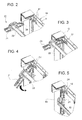
- Figures 2 to 5 are enlarged perspective views which illustrate in detail the stages in fitting the frame to the box.
- With reference initially to Figure 1, 10 indicates as a whole a rear box of a switchboard enclosure suitable for containing a plurality of electrical switches (not illustrated). A cover or front panel (not illustrated) is usually attached to the
box 10, this front panel having one or more front apertures for access to the control buttons or levers of the electrical switches housed in the enclosure. - 20 indicates a frame comprising a pair of 21 parallel, spaced apart lateral uprights. The uprights are linked by conventional crosspieces or horizontal sections 22 (DIN rails) to support the electrical switches. The
uprights 21 are detachably fixed to thebox 10 by means of screws (not illustrated) inserted throughholes 23 formed through the uprights and engaged in threadedrecesses 11 integral with thebox 10. - As are used herein, terms indicating positions and orientations, such as "vertical", "horizontal", "upper" and "lower" should be interpreted with reference to the condition in which the switchboard enclosure is fitted on a vertical wall.
- According to the present invention, the upper ends of the
uprights 21 form respectivehorizontal pins 24 constituting hooking means which can be hooked inrespective hooking seats 12 which are connected or formed integrally with the upper part of thebox 10 and aligned along a horizontal axis. In the example in the appended drawings (Figure 2), each hookingseat 12 comprises a pair of hook formations which extend upwards to engage the respective opposite ends of thepins 24. - The installer can detach the frame from the box and fit the switches on the frame by resting it on a flat surface or on a work bench to facilitate his work. Having carried out the fitting, the installer fits onto the
box 10 the assembly consisting of frame and switches. The frame, now heavier because of the switches, is hooked to the hookingseat 12 as illustrated in Figures 2 and 3, inserting thepins 24 in theseats 12. The frame then remains suspended on thebox 11, and the weight of the frame itself and the switches hold the frame stably orientated vertically or resting against thebox 10. The installer does not therefore have to concern himself with holding or manually supporting the frame while he fixes it to the box by screwing the fixing screws into theholes - In the example illustrated in the drawings, the uprights provide hooking
pins box 10 has further hookingseats 13 at the bottom of the lower part, in order to ensure that there is always the possibility of hooking the frame from its upper part even if this is fitted upside-down, and therefore to benefit from the aforementioned advantages. - The invention is of course not limited to the embodiment described and illustrated here, which has been given purely by way of example of the enclosure; the invention is however open to modification of shape and layout of parts, construction details and materials used. For example, the hooking means 12 and the
related hooking seats 12 may be formed of moulded plastics material in a single piece with therespective uprights 21 and with thebox 10, as in the embodiment illustrated in the drawings, or may consist of separate pieces or different materials (for example of metal).
Claims (8)
- A switchboard enclosure, comprising:- a box (10) for containing a plurality of electrical switches;- a frame (20) removably fixable (11, 23) to the box (10) and comprising a pair of vertical uprights (21) connected by horizontal crosspieces (22) for supporting electrical switches;characterized by comprising
hooking means (24) formed at the upper ends of the uprights (21) and corresponding hooking seats (12) which are secured or integral with an upper part of the box to hook and suspend the frame (20) in a stable position which is substantially vertical or adjacent to the box (10). - A box (10) for a switchboard enclosure, for containing a plurality of electrical switches, the box being provided with fixing means or seats (11) in order to detachably fix a frame (20) comprising a pair of vertical uprights (21) linked by horizontal crosspieces (22) for supporting electrical switches;
characterized in that it comprises hooking seats (12) which are secured to or integral with an upper part of the box (1) to hook and suspend the frame (20) in a stable position which is substantially vertical or adjacent to the box (10). - A box according to claim 2, characterized in that the hooking seats (12) comprise at least one pair of hooking seats (12) aligned in a horizontal direction.
- A box according to claim 2 or claim 3, characterized in that the hooking seats (12) comprise hook formations which extend upwards.
- A box according to claim 2, characterized in that it comprises two pairs of said hooking seats (12, 13) placed close to vertically opposed sides of the box.
- An upright (21) for a support frame (20) for electrical switches, wherein the frame provides seats or means (23) for removably fixing to a box (10) of a switchboard enclosure, characterized in that the support provides, at least at one of its ends, a hooking means (24) for hooking and suspending the frame (20) at a corresponding hooking seat (12) of the box (10).
- An upright according to claim 6, characterized in that it comprises, at each of its ends, one of said hooking means (24, 25) .
- An upright according to any one of the preceding claims, characterized in that the hooking means (24, 25) comprise at least one pair of pins (24) extending transversely to the uprights (21) and aligned transversely to each other.
Applications Claiming Priority (1)
| Application Number | Priority Date | Filing Date | Title |
|---|---|---|---|
| ITTO20060004 ITTO20060004U1 (en) | 2006-01-09 | 2006-01-09 | ASSEMBLY OF A FRAME FOR SUPPORTING ELECTRIC SWITCHES IN AN ENCLOSURE OF AN ELECTRIC PANEL. |
Publications (2)
| Publication Number | Publication Date |
|---|---|
| EP1806816A1 true EP1806816A1 (en) | 2007-07-11 |
| EP1806816B1 EP1806816B1 (en) | 2013-07-31 |
Family
ID=38031857
Family Applications (1)
| Application Number | Title | Priority Date | Filing Date |
|---|---|---|---|
| EP20070100092 Not-in-force EP1806816B1 (en) | 2006-01-09 | 2007-01-04 | Mounting of a support frame for electrical switches |
Country Status (3)
| Country | Link |
|---|---|
| EP (1) | EP1806816B1 (en) |
| ES (1) | ES2433094T3 (en) |
| IT (1) | ITTO20060004U1 (en) |
Cited By (1)
| Publication number | Priority date | Publication date | Assignee | Title |
|---|---|---|---|---|
| FR2952275A1 (en) * | 2009-11-05 | 2011-05-06 | Legrand France | DEVICE FOR MOUNTING A CHASSIS AMOUNT ON THE BACKGROUND OF AN ELECTRICAL BOX AND AN ELECTRICAL BOX COMPRISING SUCH A DEVICE |
Citations (3)
| Publication number | Priority date | Publication date | Assignee | Title |
|---|---|---|---|---|
| EP0989649A1 (en) | 1998-09-22 | 2000-03-29 | Legrand | Carrier for electrical apparatus |
| FR2791515A1 (en) * | 1999-03-25 | 2000-09-29 | Mecelec Ind | Protective housing for mechanical, electrical or telephone type equipment, has access opening for enclosed equipment |
| EP1172909A1 (en) | 2000-07-14 | 2002-01-16 | Bocchiotti Societa'per L'industria Elettrotecnica S.P.A. | Control unit for electrical systems with improved component arrangement |
-
2006
- 2006-01-09 IT ITTO20060004 patent/ITTO20060004U1/en unknown
-
2007
- 2007-01-04 ES ES07100092T patent/ES2433094T3/en active Active
- 2007-01-04 EP EP20070100092 patent/EP1806816B1/en not_active Not-in-force
Patent Citations (3)
| Publication number | Priority date | Publication date | Assignee | Title |
|---|---|---|---|---|
| EP0989649A1 (en) | 1998-09-22 | 2000-03-29 | Legrand | Carrier for electrical apparatus |
| FR2791515A1 (en) * | 1999-03-25 | 2000-09-29 | Mecelec Ind | Protective housing for mechanical, electrical or telephone type equipment, has access opening for enclosed equipment |
| EP1172909A1 (en) | 2000-07-14 | 2002-01-16 | Bocchiotti Societa'per L'industria Elettrotecnica S.P.A. | Control unit for electrical systems with improved component arrangement |
Cited By (2)
| Publication number | Priority date | Publication date | Assignee | Title |
|---|---|---|---|---|
| FR2952275A1 (en) * | 2009-11-05 | 2011-05-06 | Legrand France | DEVICE FOR MOUNTING A CHASSIS AMOUNT ON THE BACKGROUND OF AN ELECTRICAL BOX AND AN ELECTRICAL BOX COMPRISING SUCH A DEVICE |
| EP2341589A1 (en) | 2009-11-05 | 2011-07-06 | Legrand France | Device for installing a frame upright on the bottom of an electric box and electric box including such a device |
Also Published As
| Publication number | Publication date |
|---|---|
| ITTO20060004U1 (en) | 2007-07-10 |
| EP1806816B1 (en) | 2013-07-31 |
| ES2433094T3 (en) | 2013-12-09 |
Similar Documents
| Publication | Publication Date | Title |
|---|---|---|
| JP3854868B2 (en) | Showcase rack equipment | |
| US20120103925A1 (en) | Shelving System | |
| WO2008022058A2 (en) | Electronic equipment cabinet expansion kit with offset brackets | |
| US6814417B2 (en) | Switchgear cabinet | |
| US20150016796A1 (en) | Rack-mountable telecommunications patch panel | |
| US6443322B1 (en) | Wall mount enclosure having installation features for multiple separately-installed components | |
| EP1806816B1 (en) | Mounting of a support frame for electrical switches | |
| JP4518815B2 (en) | Storage shelf and experimental table provided with the same | |
| JP2002176275A (en) | OA equipment loading device | |
| JP5625157B2 (en) | Base structure of electrical equipment storage box | |
| JP6796453B2 (en) | Box for information distribution board | |
| JP6508799B2 (en) | Table system | |
| JP2004039820A (en) | Equipment storage box | |
| JP2014113296A (en) | Desk | |
| JP6692143B2 (en) | Storage box suspension structure | |
| CN108700501A (en) | Climate Test Equipment | |
| JP2009082485A (en) | Drawer | |
| JP2017119994A (en) | Suspension structure, suspension device, and steady rest device | |
| JP6327599B2 (en) | Table system | |
| KR101134205B1 (en) | Bracket of electronic device | |
| JP2000070051A (en) | Desk for office automation equipment | |
| KR101744575B1 (en) | Accessible control panel for overhead electrical apparatus in a suspended ceiling system | |
| KR101631490B1 (en) | Accessories hanger | |
| CN211450246U (en) | Blind hanging automatic guiding wall hanging structure | |
| JP2019197760A (en) | Box for information power distribution board |
Legal Events
| Date | Code | Title | Description |
|---|---|---|---|
| PUAI | Public reference made under article 153(3) epc to a published international application that has entered the european phase |
Free format text: ORIGINAL CODE: 0009012 |
|
| AK | Designated contracting states |
Kind code of ref document: A1 Designated state(s): AT BE BG CH CY CZ DE DK EE ES FI FR GB GR HU IE IS IT LI LT LU LV MC NL PL PT RO SE SI SK TR |
|
| AX | Request for extension of the european patent |
Extension state: AL BA HR MK YU |
|
| 17P | Request for examination filed |
Effective date: 20071205 |
|
| AKX | Designation fees paid |
Designated state(s): AT BE BG CH CY CZ DE DK EE ES FI FR GB GR HU IE IS IT LI LT LU LV MC NL PL PT RO SE SI SK TR |
|
| GRAP | Despatch of communication of intention to grant a patent |
Free format text: ORIGINAL CODE: EPIDOSNIGR1 |
|
| GRAS | Grant fee paid |
Free format text: ORIGINAL CODE: EPIDOSNIGR3 |
|
| GRAA | (expected) grant |
Free format text: ORIGINAL CODE: 0009210 |
|
| AK | Designated contracting states |
Kind code of ref document: B1 Designated state(s): AT BE BG CH CY CZ DE DK EE ES FI FR GB GR HU IE IS IT LI LT LU LV MC NL PL PT RO SE SI SK TR |
|
| RAP1 | Party data changed (applicant data changed or rights of an application transferred) |
Owner name: SCHNEIDER ELECTRIC INDUSTRIES SAS |
|
| REG | Reference to a national code |
Ref country code: GB Ref legal event code: FG4D Ref country code: CH Ref legal event code: EP |
|
| REG | Reference to a national code |
Ref country code: AT Ref legal event code: REF Ref document number: 625118 Country of ref document: AT Kind code of ref document: T Effective date: 20130815 |
|
| REG | Reference to a national code |
Ref country code: IE Ref legal event code: FG4D |
|
| REG | Reference to a national code |
Ref country code: DE Ref legal event code: R096 Ref document number: 602007031957 Country of ref document: DE Effective date: 20130926 |
|
| REG | Reference to a national code |
Ref country code: NL Ref legal event code: T3 |
|
| REG | Reference to a national code |
Ref country code: ES Ref legal event code: FG2A Ref document number: 2433094 Country of ref document: ES Kind code of ref document: T3 Effective date: 20131209 |
|
| REG | Reference to a national code |
Ref country code: AT Ref legal event code: MK05 Ref document number: 625118 Country of ref document: AT Kind code of ref document: T Effective date: 20130731 |
|
| REG | Reference to a national code |
Ref country code: LT Ref legal event code: MG4D |
|
| PG25 | Lapsed in a contracting state [announced via postgrant information from national office to epo] |
Ref country code: IS Free format text: LAPSE BECAUSE OF FAILURE TO SUBMIT A TRANSLATION OF THE DESCRIPTION OR TO PAY THE FEE WITHIN THE PRESCRIBED TIME-LIMIT Effective date: 20131130 Ref country code: PT Free format text: LAPSE BECAUSE OF FAILURE TO SUBMIT A TRANSLATION OF THE DESCRIPTION OR TO PAY THE FEE WITHIN THE PRESCRIBED TIME-LIMIT Effective date: 20131202 Ref country code: BE Free format text: LAPSE BECAUSE OF FAILURE TO SUBMIT A TRANSLATION OF THE DESCRIPTION OR TO PAY THE FEE WITHIN THE PRESCRIBED TIME-LIMIT Effective date: 20130731 Ref country code: AT Free format text: LAPSE BECAUSE OF FAILURE TO SUBMIT A TRANSLATION OF THE DESCRIPTION OR TO PAY THE FEE WITHIN THE PRESCRIBED TIME-LIMIT Effective date: 20130731 Ref country code: LT Free format text: LAPSE BECAUSE OF FAILURE TO SUBMIT A TRANSLATION OF THE DESCRIPTION OR TO PAY THE FEE WITHIN THE PRESCRIBED TIME-LIMIT Effective date: 20130731 Ref country code: SE Free format text: LAPSE BECAUSE OF FAILURE TO SUBMIT A TRANSLATION OF THE DESCRIPTION OR TO PAY THE FEE WITHIN THE PRESCRIBED TIME-LIMIT Effective date: 20130731 Ref country code: CY Free format text: LAPSE BECAUSE OF FAILURE TO SUBMIT A TRANSLATION OF THE DESCRIPTION OR TO PAY THE FEE WITHIN THE PRESCRIBED TIME-LIMIT Effective date: 20130717 |
|
| PG25 | Lapsed in a contracting state [announced via postgrant information from national office to epo] |
Ref country code: SI Free format text: LAPSE BECAUSE OF FAILURE TO SUBMIT A TRANSLATION OF THE DESCRIPTION OR TO PAY THE FEE WITHIN THE PRESCRIBED TIME-LIMIT Effective date: 20130731 Ref country code: PL Free format text: LAPSE BECAUSE OF FAILURE TO SUBMIT A TRANSLATION OF THE DESCRIPTION OR TO PAY THE FEE WITHIN THE PRESCRIBED TIME-LIMIT Effective date: 20130731 Ref country code: LV Free format text: LAPSE BECAUSE OF FAILURE TO SUBMIT A TRANSLATION OF THE DESCRIPTION OR TO PAY THE FEE WITHIN THE PRESCRIBED TIME-LIMIT Effective date: 20130731 Ref country code: GR Free format text: LAPSE BECAUSE OF FAILURE TO SUBMIT A TRANSLATION OF THE DESCRIPTION OR TO PAY THE FEE WITHIN THE PRESCRIBED TIME-LIMIT Effective date: 20131101 Ref country code: FI Free format text: LAPSE BECAUSE OF FAILURE TO SUBMIT A TRANSLATION OF THE DESCRIPTION OR TO PAY THE FEE WITHIN THE PRESCRIBED TIME-LIMIT Effective date: 20130731 |
|
| PG25 | Lapsed in a contracting state [announced via postgrant information from national office to epo] |
Ref country code: CY Free format text: LAPSE BECAUSE OF FAILURE TO SUBMIT A TRANSLATION OF THE DESCRIPTION OR TO PAY THE FEE WITHIN THE PRESCRIBED TIME-LIMIT Effective date: 20130731 |
|
| PG25 | Lapsed in a contracting state [announced via postgrant information from national office to epo] |
Ref country code: CZ Free format text: LAPSE BECAUSE OF FAILURE TO SUBMIT A TRANSLATION OF THE DESCRIPTION OR TO PAY THE FEE WITHIN THE PRESCRIBED TIME-LIMIT Effective date: 20130731 Ref country code: SK Free format text: LAPSE BECAUSE OF FAILURE TO SUBMIT A TRANSLATION OF THE DESCRIPTION OR TO PAY THE FEE WITHIN THE PRESCRIBED TIME-LIMIT Effective date: 20130731 Ref country code: EE Free format text: LAPSE BECAUSE OF FAILURE TO SUBMIT A TRANSLATION OF THE DESCRIPTION OR TO PAY THE FEE WITHIN THE PRESCRIBED TIME-LIMIT Effective date: 20130731 Ref country code: RO Free format text: LAPSE BECAUSE OF FAILURE TO SUBMIT A TRANSLATION OF THE DESCRIPTION OR TO PAY THE FEE WITHIN THE PRESCRIBED TIME-LIMIT Effective date: 20130731 Ref country code: DK Free format text: LAPSE BECAUSE OF FAILURE TO SUBMIT A TRANSLATION OF THE DESCRIPTION OR TO PAY THE FEE WITHIN THE PRESCRIBED TIME-LIMIT Effective date: 20130731 |
|
| PLBE | No opposition filed within time limit |
Free format text: ORIGINAL CODE: 0009261 |
|
| STAA | Information on the status of an ep patent application or granted ep patent |
Free format text: STATUS: NO OPPOSITION FILED WITHIN TIME LIMIT |
|
| 26N | No opposition filed |
Effective date: 20140502 |
|
| REG | Reference to a national code |
Ref country code: HU Ref legal event code: AG4A Ref document number: E019574 Country of ref document: HU |
|
| REG | Reference to a national code |
Ref country code: DE Ref legal event code: R119 Ref document number: 602007031957 Country of ref document: DE |
|
| REG | Reference to a national code |
Ref country code: DE Ref legal event code: R097 Ref document number: 602007031957 Country of ref document: DE Effective date: 20140502 |
|
| PG25 | Lapsed in a contracting state [announced via postgrant information from national office to epo] |
Ref country code: LU Free format text: LAPSE BECAUSE OF FAILURE TO SUBMIT A TRANSLATION OF THE DESCRIPTION OR TO PAY THE FEE WITHIN THE PRESCRIBED TIME-LIMIT Effective date: 20140104 Ref country code: MC Free format text: LAPSE BECAUSE OF FAILURE TO SUBMIT A TRANSLATION OF THE DESCRIPTION OR TO PAY THE FEE WITHIN THE PRESCRIBED TIME-LIMIT Effective date: 20130731 |
|
| REG | Reference to a national code |
Ref country code: CH Ref legal event code: PL |
|
| GBPC | Gb: european patent ceased through non-payment of renewal fee |
Effective date: 20140104 |
|
| REG | Reference to a national code |
Ref country code: DE Ref legal event code: R119 Ref document number: 602007031957 Country of ref document: DE Effective date: 20140801 |
|
| PG25 | Lapsed in a contracting state [announced via postgrant information from national office to epo] |
Ref country code: CH Free format text: LAPSE BECAUSE OF NON-PAYMENT OF DUE FEES Effective date: 20140131 Ref country code: LI Free format text: LAPSE BECAUSE OF NON-PAYMENT OF DUE FEES Effective date: 20140131 Ref country code: DE Free format text: LAPSE BECAUSE OF NON-PAYMENT OF DUE FEES Effective date: 20140801 |
|
| REG | Reference to a national code |
Ref country code: IE Ref legal event code: MM4A |
|
| PG25 | Lapsed in a contracting state [announced via postgrant information from national office to epo] |
Ref country code: GB Free format text: LAPSE BECAUSE OF NON-PAYMENT OF DUE FEES Effective date: 20140104 |
|
| PG25 | Lapsed in a contracting state [announced via postgrant information from national office to epo] |
Ref country code: IE Free format text: LAPSE BECAUSE OF NON-PAYMENT OF DUE FEES Effective date: 20140104 |
|
| REG | Reference to a national code |
Ref country code: FR Ref legal event code: PLFP Year of fee payment: 10 |
|
| PG25 | Lapsed in a contracting state [announced via postgrant information from national office to epo] |
Ref country code: BG Free format text: LAPSE BECAUSE OF FAILURE TO SUBMIT A TRANSLATION OF THE DESCRIPTION OR TO PAY THE FEE WITHIN THE PRESCRIBED TIME-LIMIT Effective date: 20130731 |
|
| PG25 | Lapsed in a contracting state [announced via postgrant information from national office to epo] |
Ref country code: TR Free format text: LAPSE BECAUSE OF FAILURE TO SUBMIT A TRANSLATION OF THE DESCRIPTION OR TO PAY THE FEE WITHIN THE PRESCRIBED TIME-LIMIT Effective date: 20130731 |
|
| REG | Reference to a national code |
Ref country code: FR Ref legal event code: PLFP Year of fee payment: 11 |
|
| REG | Reference to a national code |
Ref country code: FR Ref legal event code: PLFP Year of fee payment: 12 |
|
| PGFP | Annual fee paid to national office [announced via postgrant information from national office to epo] |
Ref country code: NL Payment date: 20240126 Year of fee payment: 18 |
|
| PGFP | Annual fee paid to national office [announced via postgrant information from national office to epo] |
Ref country code: ES Payment date: 20240201 Year of fee payment: 18 |
|
| PGFP | Annual fee paid to national office [announced via postgrant information from national office to epo] |
Ref country code: HU Payment date: 20240124 Year of fee payment: 18 |
|
| PGFP | Annual fee paid to national office [announced via postgrant information from national office to epo] |
Ref country code: IT Payment date: 20240122 Year of fee payment: 18 Ref country code: FR Payment date: 20240125 Year of fee payment: 18 |
|
| REG | Reference to a national code |
Ref country code: NL Ref legal event code: MM Effective date: 20250201 |
|
| PG25 | Lapsed in a contracting state [announced via postgrant information from national office to epo] |
Ref country code: HU Free format text: LAPSE BECAUSE OF NON-PAYMENT OF DUE FEES Effective date: 20250105 |
|
| PG25 | Lapsed in a contracting state [announced via postgrant information from national office to epo] |
Ref country code: NL Free format text: LAPSE BECAUSE OF NON-PAYMENT OF DUE FEES Effective date: 20250201 |
|
| PG25 | Lapsed in a contracting state [announced via postgrant information from national office to epo] |
Ref country code: FR Free format text: LAPSE BECAUSE OF NON-PAYMENT OF DUE FEES Effective date: 20250131 |
|
| PG25 | Lapsed in a contracting state [announced via postgrant information from national office to epo] |
Ref country code: IT Free format text: LAPSE BECAUSE OF NON-PAYMENT OF DUE FEES Effective date: 20250104 |
|
| REG | Reference to a national code |
Ref country code: ES Ref legal event code: FD2A Effective date: 20260226 |
|
| PG25 | Lapsed in a contracting state [announced via postgrant information from national office to epo] |
Ref country code: ES Free format text: LAPSE BECAUSE OF NON-PAYMENT OF DUE FEES Effective date: 20250105 |