EP1806565A1 - Sensor module - Google Patents
Sensor module Download PDFInfo
- Publication number
- EP1806565A1 EP1806565A1 EP06077303A EP06077303A EP1806565A1 EP 1806565 A1 EP1806565 A1 EP 1806565A1 EP 06077303 A EP06077303 A EP 06077303A EP 06077303 A EP06077303 A EP 06077303A EP 1806565 A1 EP1806565 A1 EP 1806565A1
- Authority
- EP
- European Patent Office
- Prior art keywords
- sensor
- sensor module
- low temperature
- metal
- ceramic substrate
- Prior art date
- Legal status (The legal status is an assumption and is not a legal conclusion. Google has not performed a legal analysis and makes no representation as to the accuracy of the status listed.)
- Withdrawn
Links
- 239000002184 metal Substances 0.000 claims abstract description 29
- 239000000758 substrate Substances 0.000 claims abstract description 21
- 239000000919 ceramic Substances 0.000 claims abstract description 17
- 230000001133 acceleration Effects 0.000 description 7
- PNEYBMLMFCGWSK-UHFFFAOYSA-N aluminium oxide Inorganic materials [O-2].[O-2].[O-2].[Al+3].[Al+3] PNEYBMLMFCGWSK-UHFFFAOYSA-N 0.000 description 6
- 238000001514 detection method Methods 0.000 description 4
- 229910000679 solder Inorganic materials 0.000 description 3
- 230000000694 effects Effects 0.000 description 2
- 239000000463 material Substances 0.000 description 2
- 230000004308 accommodation Effects 0.000 description 1
- 230000002411 adverse Effects 0.000 description 1
- 230000004888 barrier function Effects 0.000 description 1
- 239000003990 capacitor Substances 0.000 description 1
- 238000009459 flexible packaging Methods 0.000 description 1
- 238000012986 modification Methods 0.000 description 1
- 230000004048 modification Effects 0.000 description 1
Images
Classifications
-
- G—PHYSICS
- G01—MEASURING; TESTING
- G01D—MEASURING NOT SPECIALLY ADAPTED FOR A SPECIFIC VARIABLE; ARRANGEMENTS FOR MEASURING TWO OR MORE VARIABLES NOT COVERED IN A SINGLE OTHER SUBCLASS; TARIFF METERING APPARATUS; MEASURING OR TESTING NOT OTHERWISE PROVIDED FOR
- G01D11/00—Component parts of measuring arrangements not specially adapted for a specific variable
- G01D11/24—Housings ; Casings for instruments
- G01D11/245—Housings for sensors
-
- G—PHYSICS
- G01—MEASURING; TESTING
- G01P—MEASURING LINEAR OR ANGULAR SPEED, ACCELERATION, DECELERATION, OR SHOCK; INDICATING PRESENCE, ABSENCE, OR DIRECTION, OF MOVEMENT
- G01P1/00—Details of instruments
- G01P1/02—Housings
- G01P1/023—Housings for acceleration measuring devices
Definitions
- the present invention generally relates to sensors and, more particularly, relates to packaged sensor modules, such as crash sensor modules for use on vehicles.
- Electronic crash sensors are commonly employed on vehicles to sense vehicle dynamics.
- satellite crash sensors are used for vehicle crash detection systems to sense frontal and side impact during a vehicle crash (collision).
- vehicle crash detection systems To effectively detect vehicle crashes, many vehicle crash detection systems require satellite crash sensors mounted in crush zones of the vehicle.
- the signal outputs of satellite crash sensors located in select crash zones typically offer optimal signal-to-noise ratio.
- vehicle crash detection systems require several satellite crash sensors at selected locations to ensure accurate detection of a vehicle crash.
- air bag deployment systems typically employ a multitude of sensors for sensing longitudinal and/or lateral acceleration (or deceleration).
- sensors for sensing longitudinal and/or lateral acceleration (or deceleration).
- vehicles are typically equipped with pressure sensors and acceleration sensors (accelerometers).
- Pressure sensors are generally located in the vehicle door crush zone.
- Accelerometers are commonly located in a rigid beam, such as the vehicle A-pillar.
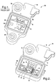
- FIG. 1 One example of a conventional satellite crash sensor module employed on a vehicle is illustrated in FIG. 1.
- the conventional sensor module 100 shown includes a plastic overmolded housing 112 and a printed circuit board 140 made from an alumina hybrid substrate.
- the circuit board substrate 140 is generally located in a recessed chamber 114 in housing 112, which is typically covered.
- the housing 112 is bolted to a vehicle via bolts extending through two mounting holes 116 and 117, and the connector end 118 is plugged into an electrical interface connector.
- the sensor 124 and related sensor signal processing electronics 144 are generally located on the alumina hybrid substrate 140 or FR4 printed circuit board.
- the placement of the sensor on an alumina-based substrate allows for a cost affordable sensor module, however, a number of drawbacks exist.
- the alumina-based substrate is relatively large as compared to the circuitry used in a typical satellite crash sensor. Additionally, there is generally little flexibility and insufficient room to add a second sensing technology within a common housing. Also, the electromagnetic interference (EMI) requirements of an alumina-based sensor are generally difficult to meet due to the large area and lack of adequate shielding.
- the housing generally must be sufficiently rigid to ensure that the crash signals are accurately transmitted to the sensor on the substrate. Further, the large area of the alumina-based substrate generally requires multiple mounting bolts to ensure a high resonant frequency to avoid distortion of input signals generated during a crash.
- a compact and cost affordable sensor module It is therefore desirable to provide for a compact and cost affordable sensor module.
- a sensor module that may be conveniently employed as a crash sensor on a vehicle. It is further desirable to provide for such a crash sensor that is relatively immune to electromagnetic interference and can be easily mounted onto the vehicle.
- a compact and cost affordable sensor module includes a housing and a low temperature co-fired ceramic substrate located on the housing.
- a sensor is located on the low temperature co-fired ceramic substrate.
- signal processing circuitry is located on the low temperature co-fired ceramic substrate.
- the sensor module further includes a metal shield substantially encapsulating the sensor.
- the sensor module is cost affordable, compact and generally immune to electromagnetic interference. According to one aspect of the present invention, the sensor module may be employed as a crash sensor module for use on a vehicle to sense pressure and/or acceleration, according to various embodiments.
- a satellite crash sensor module 10 is generally illustrated according to one embodiment of the present invention.
- the sensor module 10 contains two sensors in a packaged module capable of sensing pressure and acceleration.
- the sensing module 10 may contain other sensing devices.
- the sensor module 10 may contain one or more sensors for sensing pressure, acceleration, velocity and other conditions alone or in combination, according to other embodiments. While the sensor module 10 is described herein as a satellite crash sensor module, it should be appreciated that the sensor module 10 may be employed in various applications on and off a vehicle.
- the sensor module 10 includes a housing 12 generally having a recessed cavity 14 for receiving the sensors and related circuitry.
- the housing 12 may be made of plastic or metal.
- a metal grommet is formed extending through housing 12 generally defining a single mounting hole 16 for receiving a bolt to fasten the module 10 onto a rigid structure, such as an A-pillar or a door of a vehicle.
- the housing 12 further includes an electrical connecting end 18 for matingly receiving an electrical interface connector to allow for signal communications, as should be evident to those skilled in the art.
- the cavity 14 of housing 12 houses one, two or more sensors and various signal processing circuitry as described herein. It should be appreciated that the cavity 14 may be closed via a top cover (not shown) to encapsulate the sensor(s) and processing circuitry within housing 12.
- the top cover may include a plastic lid adhered or fastened to housing 12, or a conformal coat barrier which keeps out moisture.
- the sensor module 10 contains a pair of sensors 22 and 32 mounted onto respective first and second low temperature co-fired ceramic substrates 20 and 30.
- the first sensor 22 may include a pressure sensing element, such as a microelectromechanical system (MEMS) pressure sensor, located on the bottom side of the first low temperature co-fired ceramic (LTCC) 20.
- MEMS microelectromechanical system
- LTCC first low temperature co-fired ceramic
- the signal processing circuitry 24 may include application specific integrated circuitry (ASIC) for providing signal compensation and other processing of the sensor signals.
- ASIC application specific integrated circuitry
- Also mounted on the top surface of the first LTCC 20 are various signal compact pads 54 and a plurality of circuit components 50 which may include resistors, capacitors and other circuit components.
- the first and second LTCC 20 and second LTCC 30 are made from multiple thin layers of ceramic.
- the multiple thin layers of ceramic are co-fired at a low temperature (e.g., 850°C) to form the LTCCs 20 and 30.
- a low temperature e.g., 850°C
- low temperature co-fired ceramics are commercially available from E.I. du Pont de Nemours and Company, referred to as Green TapeTM LTCC materials, which are made using multilayer strip lines or a combination of strip lines and microstrip structures.
- the LTCC materials offer dimensional stability, low dielectric loss and good performance.
- the pressure sensor 22 and processing circuitry 24 are shown substantially encapsulated by a metal shield formed of an upper metal can 26 and a lower metal can 28.
- the upper metal can 26 is connected to the top surface of the first LTCC 20 via a solder ring 56.
- the top metal can 26 thereby substantially covers the processing circuitry 24.
- the bottom metal can 28 is connected to the bottom side of the first LTCC 20 via a solder ring 58 to substantially encapsulate the pressure sensor 22. While metal cans 26 and 28 are shown soldered to the LTCC via solder rings 56 and 58, respectively, it should be appreciated that the metal cans 26 and 28 may be adhered or otherwise connected to the LTCC 20.
- the bottom metal can 28 covering pressure sensor 22 has a vent hole 48 formed therein. Additionally, the housing 12 has a vent hole 46, substantially lined up with vent hole 48 that leads to the ambient environment. The vent holes 46 and 48 allow input pressure waves to get to the pressure sensor 22, without requiring a cover closure. This reduces cost and minimizes time delay in the generated crash signals.
- the second sensor 32 referred to in the first embodiment as an accelerometer, is mounted onto the second LTCC 30 and is substantially encapsulated by a bottom metal can 38.
- the accelerometer sensor 32 may include a microelectromechanical system (MEMS) accelerometer for sensing linear or angular acceleration, according to one embodiment.
- processing circuitry 34 such as in the form of an ASIC according to one embodiment, is mounted on the top surface of the second LTCC 30.
- a top metal can 36 substantially covers the processing circuitry 34. The top metal can 36 and bottom metal can 38 thereby substantially encapsulate the accelerometer sensor 32 and processing circuitry 34, in a manner similar to that described in connection with the first sensor 22.
- multiple sensors such as the pressure sensor 22 and accelerometer 32, can be located on a single LTCC 20 as shown in FIG. 8.
- both pressure sensor 22 and accelerometer 32 are substantially encapsulated together on the bottom side by metal can 28.
- the signal processing circuitry may then be located on the opposite side of the LTCC 20 and substantially encapsulated by an upper metal can.
- an alternative sensor module 10' is further illustrated according to a further embodiment of the present invention.
- the alternative sensor module 10' is shown containing a single sensor, such as pressure sensor 22, located on a single LTCC 20.
- the LTCC 20 and pressure sensor 20 are mounted on the LTCC 20 and are substantially encapsulated by a top metal can 24 and bottom metal can as described above in connection with the other embodiments.
- the sensing module 10' may contain other sensing elements, such as an accelerometer. It should further be appreciated that more than two sensing elements may be employed on the sensor module 10 or 10', without departing from the teachings of the present invention.
- the sensor module 10 or 10' advantageously is compact and requires less volume. Additionally, by utilizing a smaller housing, only a single bolt is required to fasten the sensor module 10 or 10' to a rigid structure while still maintaining a sufficiently high resonant frequency to ensure that generated crash signals are not distorted.
- the resultant flexible packaging approach achieved with the sensor module 10 or 10' allows for the accommodation of one or more pressure sensors, accelerometers, other sensors, or any combination, which is particularly useful for use as crash satellite sensors employed onboard a vehicle. Further, the sensor module 10 or 10' is reliable and minimizes the adverse effects of electromagnetic interference.
Landscapes
- Physics & Mathematics (AREA)
- General Physics & Mathematics (AREA)
- Measuring Fluid Pressure (AREA)
- Pressure Sensors (AREA)
Abstract
Description
- The present invention generally relates to sensors and, more particularly, relates to packaged sensor modules, such as crash sensor modules for use on vehicles.
- Electronic crash sensors are commonly employed on vehicles to sense vehicle dynamics. In particular, satellite crash sensors are used for vehicle crash detection systems to sense frontal and side impact during a vehicle crash (collision). To effectively detect vehicle crashes, many vehicle crash detection systems require satellite crash sensors mounted in crush zones of the vehicle. The signal outputs of satellite crash sensors located in select crash zones typically offer optimal signal-to-noise ratio.
- Many vehicle crash detection systems require several satellite crash sensors at selected locations to ensure accurate detection of a vehicle crash. For example, air bag deployment systems typically employ a multitude of sensors for sensing longitudinal and/or lateral acceleration (or deceleration). Currently, vehicles are typically equipped with pressure sensors and acceleration sensors (accelerometers). Pressure sensors are generally located in the vehicle door crush zone. Accelerometers are commonly located in a rigid beam, such as the vehicle A-pillar.
- In conventional packaged sensor modules, pressure sensors and/or accelerometers are typically packaged individually. One example of a conventional satellite crash sensor module employed on a vehicle is illustrated in FIG. 1. The
conventional sensor module 100 shown includes a plastic overmoldedhousing 112 and a printedcircuit board 140 made from an alumina hybrid substrate. Thecircuit board substrate 140 is generally located in arecessed chamber 114 inhousing 112, which is typically covered. Thehousing 112 is bolted to a vehicle via bolts extending through twomounting holes connector end 118 is plugged into an electrical interface connector. Thesensor 124 and related sensorsignal processing electronics 144 are generally located on thealumina hybrid substrate 140 or FR4 printed circuit board. - The placement of the sensor on an alumina-based substrate allows for a cost affordable sensor module, however, a number of drawbacks exist. The alumina-based substrate is relatively large as compared to the circuitry used in a typical satellite crash sensor. Additionally, there is generally little flexibility and insufficient room to add a second sensing technology within a common housing. Also, the electromagnetic interference (EMI) requirements of an alumina-based sensor are generally difficult to meet due to the large area and lack of adequate shielding. The housing generally must be sufficiently rigid to ensure that the crash signals are accurately transmitted to the sensor on the substrate. Further, the large area of the alumina-based substrate generally requires multiple mounting bolts to ensure a high resonant frequency to avoid distortion of input signals generated during a crash.
- It is therefore desirable to provide for a compact and cost affordable sensor module. In particular, it is desirable to provide for a sensor module that may be conveniently employed as a crash sensor on a vehicle. It is further desirable to provide for such a crash sensor that is relatively immune to electromagnetic interference and can be easily mounted onto the vehicle.
- In accordance with the teachings of the present invention, a compact and cost affordable sensor module is provided. The sensor module includes a housing and a low temperature co-fired ceramic substrate located on the housing. A sensor is located on the low temperature co-fired ceramic substrate. Additionally, signal processing circuitry is located on the low temperature co-fired ceramic substrate. The sensor module further includes a metal shield substantially encapsulating the sensor.
- The sensor module is cost affordable, compact and generally immune to electromagnetic interference. According to one aspect of the present invention, the sensor module may be employed as a crash sensor module for use on a vehicle to sense pressure and/or acceleration, according to various embodiments.
- These and other features, advantages and objects of the present invention will be further understood and appreciated by those skilled in the art by reference to the following specification, claims and appended drawings.
- The present invention will now be described, by way of example, with reference to the accompanying drawings, in which:
- FIG. 1 is a perspective view of a conventional satellite crash sensor module;
- FIG. 2 is a top perspective view of a crash sensor module with the cover removed, according to one embodiment of the present invention;
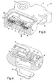
- FIG. 3 is a perspective cross-sectional view of the sensor module in FIG. 2 taken through lines III-III;
- FIG. 4 is an enlarged exploded view of section IV of FIG. 3;
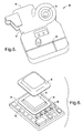
- FIG. 5 is a bottom perspective view of the sensor module shown in FIG. 2;
- FIG. 6 is an exploded view of the top of the pressure sensing portion of the sensor module;
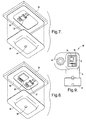
- FIG. 7 is an exploded view of the bottom of the pressure sensing portion of the pressure sensor;
- FIG. 8 is an exploded view of the bottom of a combination pressure and acceleration sensing portion of a sensor module according to another embodiment; and
- FIG. 9 is a top view of a sensor module employing a single sensor, according to a further embodiment.
- Referring now to FIGS. 1-5, a satellite
crash sensor module 10 is generally illustrated according to one embodiment of the present invention. In the first embodiment shown, thesensor module 10 contains two sensors in a packaged module capable of sensing pressure and acceleration. However, it should be appreciated that thesensing module 10 may contain other sensing devices. For example, thesensor module 10 may contain one or more sensors for sensing pressure, acceleration, velocity and other conditions alone or in combination, according to other embodiments. While thesensor module 10 is described herein as a satellite crash sensor module, it should be appreciated that thesensor module 10 may be employed in various applications on and off a vehicle. - The
sensor module 10 includes ahousing 12 generally having arecessed cavity 14 for receiving the sensors and related circuitry. Thehousing 12 may be made of plastic or metal. A metal grommet is formed extending throughhousing 12 generally defining asingle mounting hole 16 for receiving a bolt to fasten themodule 10 onto a rigid structure, such as an A-pillar or a door of a vehicle. Thehousing 12 further includes anelectrical connecting end 18 for matingly receiving an electrical interface connector to allow for signal communications, as should be evident to those skilled in the art. - The
cavity 14 ofhousing 12 houses one, two or more sensors and various signal processing circuitry as described herein. It should be appreciated that thecavity 14 may be closed via a top cover (not shown) to encapsulate the sensor(s) and processing circuitry withinhousing 12. The top cover may include a plastic lid adhered or fastened tohousing 12, or a conformal coat barrier which keeps out moisture. - In the first embodiment shown, the
sensor module 10 contains a pair ofsensors ceramic substrates first sensor 22 may include a pressure sensing element, such as a microelectromechanical system (MEMS) pressure sensor, located on the bottom side of the first low temperature co-fired ceramic (LTCC) 20. Mounted on the opposite top side of the first LTCC 20 issignal processing circuitry 24. Thesignal processing circuitry 24 may include application specific integrated circuitry (ASIC) for providing signal compensation and other processing of the sensor signals. Also mounted on the top surface of the first LTCC 20 are various signalcompact pads 54 and a plurality ofcircuit components 50 which may include resistors, capacitors and other circuit components. - The first and
second LTCC 20 andsecond LTCC 30 are made from multiple thin layers of ceramic. The multiple thin layers of ceramic are co-fired at a low temperature (e.g., 850°C) to form theLTCCs - With particular reference to FIGS. 6 and 7, the
pressure sensor 22 andprocessing circuitry 24 are shown substantially encapsulated by a metal shield formed of an upper metal can 26 and a lower metal can 28. The upper metal can 26 is connected to the top surface of thefirst LTCC 20 via asolder ring 56. The top metal can 26 thereby substantially covers theprocessing circuitry 24. Similarly, the bottom metal can 28 is connected to the bottom side of thefirst LTCC 20 via asolder ring 58 to substantially encapsulate thepressure sensor 22. Whilemetal cans metal cans LTCC 20. - The upper and
lower metal cans sensor 22 andprocessing circuitry 24 to provide electrical shielding to minimize the effects of electromagnetic interference (EMI). Additionally, themetal cans LTCC 20 and provide enhanced accuracy signals for thesensor 22. It should be appreciated that the overall surface area of theLTCC 20 is substantially smaller than the surface area of substrates employed on conventional sensor modules, such as FR4, which allows for use of a much smaller housing and an overall reducedsize sensor module 10. - The bottom metal can 28
covering pressure sensor 22 has avent hole 48 formed therein. Additionally, thehousing 12 has avent hole 46, substantially lined up withvent hole 48 that leads to the ambient environment. The vent holes 46 and 48 allow input pressure waves to get to thepressure sensor 22, without requiring a cover closure. This reduces cost and minimizes time delay in the generated crash signals. - The
second sensor 32, referred to in the first embodiment as an accelerometer, is mounted onto thesecond LTCC 30 and is substantially encapsulated by a bottom metal can 38. Theaccelerometer sensor 32 may include a microelectromechanical system (MEMS) accelerometer for sensing linear or angular acceleration, according to one embodiment. Additionally, processingcircuitry 34, such as in the form of an ASIC according to one embodiment, is mounted on the top surface of thesecond LTCC 30. Similarly, a top metal can 36 substantially covers theprocessing circuitry 34. The top metal can 36 and bottom metal can 38 thereby substantially encapsulate theaccelerometer sensor 32 andprocessing circuitry 34, in a manner similar to that described in connection with thefirst sensor 22. - According to another embodiment, multiple sensors, such as the
pressure sensor 22 andaccelerometer 32, can be located on asingle LTCC 20 as shown in FIG. 8. In this embodiment, bothpressure sensor 22 andaccelerometer 32 are substantially encapsulated together on the bottom side by metal can 28. The signal processing circuitry may then be located on the opposite side of theLTCC 20 and substantially encapsulated by an upper metal can. - Referring to FIG. 9, an alternative sensor module 10' is further illustrated according to a further embodiment of the present invention. The alternative sensor module 10' is shown containing a single sensor, such as
pressure sensor 22, located on asingle LTCC 20. TheLTCC 20 andpressure sensor 20 are mounted on theLTCC 20 and are substantially encapsulated by a top metal can 24 and bottom metal can as described above in connection with the other embodiments. - According to other embodiments, the sensing module 10' may contain other sensing elements, such as an accelerometer. It should further be appreciated that more than two sensing elements may be employed on the
sensor module 10 or 10', without departing from the teachings of the present invention. - The
sensor module 10 or 10' advantageously is compact and requires less volume. Additionally, by utilizing a smaller housing, only a single bolt is required to fasten thesensor module 10 or 10' to a rigid structure while still maintaining a sufficiently high resonant frequency to ensure that generated crash signals are not distorted. The resultant flexible packaging approach achieved with thesensor module 10 or 10' allows for the accommodation of one or more pressure sensors, accelerometers, other sensors, or any combination, which is particularly useful for use as crash satellite sensors employed onboard a vehicle. Further, thesensor module 10 or 10' is reliable and minimizes the adverse effects of electromagnetic interference. - It will be understood by those who practice the invention and those skilled in the art, that various modifications and improvements may be made to the invention without departing from the spirit of the disclosed concept. The scope of protection afforded is to be determined by the claims and by the breadth of interpretation allowed by law.
Claims (9)
- A sensor module (10) comprising:a housing (12);a low temperature co-fired ceramic substrate (20) located on the housing (12);a sensor (22) located on the low temperature co-fired ceramic substrate (20);signal processing circuitry (24) located on the low temperature co-fired ceramic substrate (20); anda metal shield (28) substantially encapsulating the sensor (22).
- The sensor module as defined in claim 1, wherein the metal shield comprises a first metal can (28) overlying the sensor (22) on one side of the low temperature co-fired ceramic substrate (20), and a second metal can (26) located on a second opposite side of the low temperature co-fired ceramic substrate (20).
- The sensor module as defined in claim 2, wherein the signal processing circuitry (24) is located on the second side of the low temperature co-fired ceramic substrate (20) and is at least partially encapsulated by the second metal can (26).
- The sensor module as defined in claim 1, wherein the signal processing circuitry (24) comprises an ASIC.
- The sensor module as defined in claim 1 further comprising another sensor (32) formed on another low temperature co-fired ceramic substrate (30), said another sensor (32) having another metal shield (38).
- The sensor module as defined in claim 5, wherein the sensors comprise a pressure sensor (22) and an accelerometer (32).
- The sensor module as defined in claim 1, wherein the sensor comprises a pressure sensor (22).
- The sensor module as defined in claim 1, wherein the sensor comprises an accelerometer (32).
- The sensor module as defined in claim 1, wherein the sensor (22) is a vehicle crash sensor.
Applications Claiming Priority (1)
| Application Number | Priority Date | Filing Date | Title |
|---|---|---|---|
| US11/328,032 US7331212B2 (en) | 2006-01-09 | 2006-01-09 | Sensor module |
Publications (1)
| Publication Number | Publication Date |
|---|---|
| EP1806565A1 true EP1806565A1 (en) | 2007-07-11 |
Family
ID=37909803
Family Applications (1)
| Application Number | Title | Priority Date | Filing Date |
|---|---|---|---|
| EP06077303A Withdrawn EP1806565A1 (en) | 2006-01-09 | 2006-12-22 | Sensor module |
Country Status (2)
| Country | Link |
|---|---|
| US (1) | US7331212B2 (en) |
| EP (1) | EP1806565A1 (en) |
Cited By (1)
| Publication number | Priority date | Publication date | Assignee | Title |
|---|---|---|---|---|
| EP3413057A1 (en) * | 2017-06-09 | 2018-12-12 | Simmonds Precision Products, Inc. | High frequency accelerometer housing |
Families Citing this family (23)
| Publication number | Priority date | Publication date | Assignee | Title |
|---|---|---|---|---|
| US7433197B2 (en) * | 2005-08-26 | 2008-10-07 | Tk Holdings Inc | Electronic module and method for sealing an electronic module |
| US20090265671A1 (en) * | 2008-04-21 | 2009-10-22 | Invensense | Mobile devices with motion gesture recognition |
| US8462109B2 (en) | 2007-01-05 | 2013-06-11 | Invensense, Inc. | Controlling and accessing content using motion processing on mobile devices |
| US8250921B2 (en) * | 2007-07-06 | 2012-08-28 | Invensense, Inc. | Integrated motion processing unit (MPU) with MEMS inertial sensing and embedded digital electronics |
| US20100071467A1 (en) * | 2008-09-24 | 2010-03-25 | Invensense | Integrated multiaxis motion sensor |
| US7934423B2 (en) | 2007-12-10 | 2011-05-03 | Invensense, Inc. | Vertically integrated 3-axis MEMS angular accelerometer with integrated electronics |
| US20090262074A1 (en) * | 2007-01-05 | 2009-10-22 | Invensense Inc. | Controlling and accessing content using motion processing on mobile devices |
| US8047075B2 (en) * | 2007-06-21 | 2011-11-01 | Invensense, Inc. | Vertically integrated 3-axis MEMS accelerometer with electronics |
| US8020441B2 (en) * | 2008-02-05 | 2011-09-20 | Invensense, Inc. | Dual mode sensing for vibratory gyroscope |
| US8141424B2 (en) * | 2008-09-12 | 2012-03-27 | Invensense, Inc. | Low inertia frame for detecting coriolis acceleration |
| US8508039B1 (en) | 2008-05-08 | 2013-08-13 | Invensense, Inc. | Wafer scale chip scale packaging of vertically integrated MEMS sensors with electronics |
| US8952832B2 (en) | 2008-01-18 | 2015-02-10 | Invensense, Inc. | Interfacing application programs and motion sensors of a device |
| US20080173107A1 (en) * | 2007-01-19 | 2008-07-24 | Autoliv Asp, Inc. | Combination pressure and acceleration sensor |
| KR101296426B1 (en) * | 2008-07-28 | 2013-08-13 | 티알더블유 오토모티브 유.에스. 엘엘씨 | Method and apparatus for packaging crash sensors |
| US8220330B2 (en) * | 2009-03-24 | 2012-07-17 | Freescale Semiconductor, Inc. | Vertically integrated MEMS sensor device with multi-stimulus sensing |
| DE102009060002A1 (en) * | 2009-12-21 | 2011-06-22 | Micro-Epsilon Messtechnik GmbH & Co. KG, 94496 | sensor |
| US9872111B2 (en) * | 2013-03-06 | 2018-01-16 | Infineon Technologies Austria Ag | Acoustic sensor package |
| KR20160024331A (en) * | 2014-08-25 | 2016-03-04 | 삼성전기주식회사 | Multi-axis sensor and method for manufacturing the same |
| US10527523B2 (en) * | 2015-12-18 | 2020-01-07 | Ge Global Sourcing Llc | Vehicle sensor assembly having an RF sensor disposed in the sensor assembly to wirelessly communicate data to outside the sensor assembly |
| JP6699243B2 (en) * | 2016-03-03 | 2020-05-27 | オムロン株式会社 | Sensor device |
| US10340211B1 (en) | 2018-03-15 | 2019-07-02 | Nxp B.V. | Sensor module with blade insert |
| US10921207B2 (en) * | 2018-03-28 | 2021-02-16 | Veoneer Us Inc. | Sensor assembly with linear contacts |
| DE102023212700A1 (en) * | 2023-12-14 | 2025-06-18 | Fraunhofer-Gesellschaft zur Förderung der angewandten Forschung eingetragener Verein | Method for producing an inertial sensor system and an inertial sensor system produced by the method |
Citations (3)
| Publication number | Priority date | Publication date | Assignee | Title |
|---|---|---|---|---|
| JP2000028629A (en) * | 1998-07-08 | 2000-01-28 | Honda Motor Co Ltd | Gas angular velocity sensor |
| US20040004554A1 (en) * | 2000-12-08 | 2004-01-08 | Regaswamy Srinivasan | Wireless multi-funtional sensor platform, system containing same and method for its use |
| US20040200279A1 (en) * | 2001-06-25 | 2004-10-14 | Tomohiro Mitani | Composite sensor for detecting angular velocity and acceleration |
Family Cites Families (6)
| Publication number | Priority date | Publication date | Assignee | Title |
|---|---|---|---|---|
| US5345823A (en) * | 1991-11-12 | 1994-09-13 | Texas Instruments Incorporated | Accelerometer |
| US6145380A (en) * | 1997-12-18 | 2000-11-14 | Alliedsignal | Silicon micro-machined accelerometer using integrated electrical and mechanical packaging |
| US6993975B2 (en) * | 2003-11-03 | 2006-02-07 | Delphi Technologies, Inc. | Pressure sensor module having stress isolation platform |
| US7231803B2 (en) * | 2004-06-11 | 2007-06-19 | Robert Bosch Gmbh | Hybrid impact sensor |
| US7038150B1 (en) * | 2004-07-06 | 2006-05-02 | Sandia Corporation | Micro environmental sensing device |
| US7683775B2 (en) * | 2005-11-30 | 2010-03-23 | Frank Levinson | Low power pulse modulation communication in mesh networks with modular sensors |
-
2006
- 2006-01-09 US US11/328,032 patent/US7331212B2/en not_active Expired - Lifetime
- 2006-12-22 EP EP06077303A patent/EP1806565A1/en not_active Withdrawn
Patent Citations (3)
| Publication number | Priority date | Publication date | Assignee | Title |
|---|---|---|---|---|
| JP2000028629A (en) * | 1998-07-08 | 2000-01-28 | Honda Motor Co Ltd | Gas angular velocity sensor |
| US20040004554A1 (en) * | 2000-12-08 | 2004-01-08 | Regaswamy Srinivasan | Wireless multi-funtional sensor platform, system containing same and method for its use |
| US20040200279A1 (en) * | 2001-06-25 | 2004-10-14 | Tomohiro Mitani | Composite sensor for detecting angular velocity and acceleration |
Cited By (2)
| Publication number | Priority date | Publication date | Assignee | Title |
|---|---|---|---|---|
| EP3413057A1 (en) * | 2017-06-09 | 2018-12-12 | Simmonds Precision Products, Inc. | High frequency accelerometer housing |
| US10788509B2 (en) | 2017-06-09 | 2020-09-29 | Simmonds Precision Products, Inc. | High frequency accelerometer housing including circuit board disposed directly above support pad |
Also Published As
| Publication number | Publication date |
|---|---|
| US20070157699A1 (en) | 2007-07-12 |
| US7331212B2 (en) | 2008-02-19 |
Similar Documents
| Publication | Publication Date | Title |
|---|---|---|
| US7331212B2 (en) | Sensor module | |
| KR100225330B1 (en) | Semiconductor sensor | |
| US6891239B2 (en) | Integrated sensor and electronics package | |
| EP2099654B1 (en) | Electric vehicle motion sensor | |
| EP2342160B1 (en) | Inertial sensor with dual cavity package and method of fabrication | |
| US7155975B2 (en) | Composite sensor for detecting angular velocity and acceleration | |
| EP1785392B1 (en) | Miniature package for translation of sensor sense axis | |
| EP0989032A2 (en) | Multi-sensor module for communicating sensor information over a vehicle data bus | |
| US8013404B2 (en) | Folded lead-frame packages for MEMS devices | |
| EP1903845A2 (en) | Electronics enclosure and method of fabricating an electronics enclosure | |
| US5503016A (en) | Vertically mounted accelerometer chip | |
| EP1630561B1 (en) | Accelerometer assembly with two possible orientations of the sensing axis relative to the housing | |
| US7196404B2 (en) | Motion detector and method of producing the same | |
| US20040244510A1 (en) | Multi-surface mounting member and electronic device | |
| US5433110A (en) | Detector having selectable multiple axes of sensitivity | |
| EP3432111B1 (en) | Control apparatus for unmanned aerial vehicle, and unmanned aerial vehicle | |
| US7147486B2 (en) | Method and apparatus for attaching a sensor assembly in a control unit | |
| EP3260821B1 (en) | Sensor package and method of producing the sensor package | |
| US7134334B2 (en) | Integrated fastener and motion detector | |
| KR20080087108A (en) | Board structure and electronic device | |
| EP4172102B1 (en) | Semiconductor package with built-in vibration isolation, thermal stability, and connector decoupling | |
| US20210123947A1 (en) | Inertial measurement apparatus, electronic instrument, and moving object | |
| US5719334A (en) | Hermetically protected sensor assembly | |
| US5714409A (en) | Method and apparatus for packaging a vehicle sensor and integrated circuit chip | |
| US12116270B2 (en) | Device for supporting MEMS and/or ASIC components |
Legal Events
| Date | Code | Title | Description |
|---|---|---|---|
| PUAI | Public reference made under article 153(3) epc to a published international application that has entered the european phase |
Free format text: ORIGINAL CODE: 0009012 |
|
| AK | Designated contracting states |
Kind code of ref document: A1 Designated state(s): AT BE BG CH CY CZ DE DK EE ES FI FR GB GR HU IE IS IT LI LT LU LV MC NL PL PT RO SE SI SK TR |
|
| AX | Request for extension of the european patent |
Extension state: AL BA HR MK YU |
|
| 17P | Request for examination filed |
Effective date: 20080111 |
|
| AKX | Designation fees paid |
Designated state(s): AT BE BG CH CY CZ DE DK EE ES FI FR GB GR HU IE IS IT LI LT LU LV MC NL PL PT RO SE SI SK TR |
|
| 17Q | First examination report despatched |
Effective date: 20080225 |
|
| STAA | Information on the status of an ep patent application or granted ep patent |
Free format text: STATUS: THE APPLICATION IS DEEMED TO BE WITHDRAWN |
|
| 18D | Application deemed to be withdrawn |
Effective date: 20130712 |