EP1806389A1 - Phosphor, process for producing the same and luminescence apparatus - Google Patents
Phosphor, process for producing the same and luminescence apparatus Download PDFInfo
- Publication number
- EP1806389A1 EP1806389A1 EP05785843A EP05785843A EP1806389A1 EP 1806389 A1 EP1806389 A1 EP 1806389A1 EP 05785843 A EP05785843 A EP 05785843A EP 05785843 A EP05785843 A EP 05785843A EP 1806389 A1 EP1806389 A1 EP 1806389A1
- Authority
- EP
- European Patent Office
- Prior art keywords
- phosphor
- crystal
- inclusive
- light
- production method
- Prior art date
- Legal status (The legal status is an assumption and is not a legal conclusion. Google has not performed a legal analysis and makes no representation as to the accuracy of the status listed.)
- Granted
Links
- OAICVXFJPJFONN-UHFFFAOYSA-N Phosphorus Chemical compound [P] OAICVXFJPJFONN-UHFFFAOYSA-N 0.000 title claims abstract description 297
- 238000000034 method Methods 0.000 title claims description 35
- 230000008569 process Effects 0.000 title description 3
- 238000004020 luminiscence type Methods 0.000 title 1
- 239000000203 mixture Substances 0.000 claims abstract description 137
- 229910052581 Si3N4 Inorganic materials 0.000 claims abstract description 43
- VYPSYNLAJGMNEJ-UHFFFAOYSA-N Silicium dioxide Chemical compound O=[Si]=O VYPSYNLAJGMNEJ-UHFFFAOYSA-N 0.000 claims abstract description 40
- 229910052751 metal Inorganic materials 0.000 claims abstract description 21
- 229910052712 strontium Inorganic materials 0.000 claims abstract description 19
- 229910052791 calcium Inorganic materials 0.000 claims abstract description 18
- 229910052788 barium Inorganic materials 0.000 claims abstract description 17
- 229910052684 Cerium Inorganic materials 0.000 claims abstract description 16
- 229910052693 Europium Inorganic materials 0.000 claims abstract description 16
- 229910052692 Dysprosium Inorganic materials 0.000 claims abstract description 14
- 229910052691 Erbium Inorganic materials 0.000 claims abstract description 14
- 229910052689 Holmium Inorganic materials 0.000 claims abstract description 14
- 229910052779 Neodymium Inorganic materials 0.000 claims abstract description 14
- 229910052772 Samarium Inorganic materials 0.000 claims abstract description 14
- 229910052771 Terbium Inorganic materials 0.000 claims abstract description 14
- 229910052775 Thulium Inorganic materials 0.000 claims abstract description 14
- 229910052769 Ytterbium Inorganic materials 0.000 claims abstract description 14
- 229910052681 coesite Inorganic materials 0.000 claims abstract description 14
- 229910052906 cristobalite Inorganic materials 0.000 claims abstract description 14
- 229910052748 manganese Inorganic materials 0.000 claims abstract description 14
- 238000010587 phase diagram Methods 0.000 claims abstract description 14
- 239000000377 silicon dioxide Substances 0.000 claims abstract description 14
- 229910052682 stishovite Inorganic materials 0.000 claims abstract description 14
- 229910052905 tridymite Inorganic materials 0.000 claims abstract description 14
- 239000007787 solid Substances 0.000 claims abstract description 12
- 229910052749 magnesium Inorganic materials 0.000 claims abstract description 9
- 239000013078 crystal Substances 0.000 claims description 152
- 239000000843 powder Substances 0.000 claims description 81
- 150000002484 inorganic compounds Chemical class 0.000 claims description 52
- 229910010272 inorganic material Inorganic materials 0.000 claims description 52
- 239000006104 solid solution Substances 0.000 claims description 45
- 238000004519 manufacturing process Methods 0.000 claims description 39
- 238000010304 firing Methods 0.000 claims description 38
- IJGRMHOSHXDMSA-UHFFFAOYSA-N Atomic nitrogen Chemical compound N#N IJGRMHOSHXDMSA-UHFFFAOYSA-N 0.000 claims description 37
- HQVNEWCFYHHQES-UHFFFAOYSA-N silicon nitride Chemical compound N12[Si]34N5[Si]62N3[Si]51N64 HQVNEWCFYHHQES-UHFFFAOYSA-N 0.000 claims description 36
- 239000012071 phase Substances 0.000 claims description 35
- 229910052757 nitrogen Inorganic materials 0.000 claims description 26
- 150000001875 compounds Chemical class 0.000 claims description 24
- 230000005284 excitation Effects 0.000 claims description 24
- 230000003213 activating effect Effects 0.000 claims description 22
- 150000004767 nitrides Chemical class 0.000 claims description 20
- 229910052760 oxygen Inorganic materials 0.000 claims description 20
- 239000007858 starting material Substances 0.000 claims description 17
- 230000001747 exhibiting effect Effects 0.000 claims description 15
- 239000002245 particle Substances 0.000 claims description 15
- 239000000126 substance Substances 0.000 claims description 15
- 239000000470 constituent Substances 0.000 claims description 14
- QVGXLLKOCUKJST-UHFFFAOYSA-N atomic oxygen Chemical compound [O] QVGXLLKOCUKJST-UHFFFAOYSA-N 0.000 claims description 13
- 239000001301 oxygen Substances 0.000 claims description 13
- KRHYYFGTRYWZRS-UHFFFAOYSA-N Fluorane Chemical compound F KRHYYFGTRYWZRS-UHFFFAOYSA-N 0.000 claims description 12
- QAOWNCQODCNURD-UHFFFAOYSA-N Sulfuric acid Chemical compound OS(O)(=O)=O QAOWNCQODCNURD-UHFFFAOYSA-N 0.000 claims description 12
- 229910001940 europium oxide Inorganic materials 0.000 claims description 12
- AEBZCFFCDTZXHP-UHFFFAOYSA-N europium(3+);oxygen(2-) Chemical compound [O-2].[O-2].[O-2].[Eu+3].[Eu+3] AEBZCFFCDTZXHP-UHFFFAOYSA-N 0.000 claims description 12
- 239000000047 product Substances 0.000 claims description 12
- 229910052710 silicon Inorganic materials 0.000 claims description 11
- 239000012298 atmosphere Substances 0.000 claims description 10
- 238000002156 mixing Methods 0.000 claims description 10
- BVKZGUZCCUSVTD-UHFFFAOYSA-L Carbonate Chemical compound [O-]C([O-])=O BVKZGUZCCUSVTD-UHFFFAOYSA-L 0.000 claims description 9
- 238000010894 electron beam technology Methods 0.000 claims description 9
- 238000005245 sintering Methods 0.000 claims description 9
- 238000011049 filling Methods 0.000 claims description 8
- 229910000765 intermetallic Inorganic materials 0.000 claims description 8
- 239000002184 metal Substances 0.000 claims description 8
- 229910002797 Si3–xAlx Inorganic materials 0.000 claims description 7
- 239000007789 gas Substances 0.000 claims description 7
- 239000012535 impurity Substances 0.000 claims description 7
- 238000010298 pulverizing process Methods 0.000 claims description 7
- 229910052582 BN Inorganic materials 0.000 claims description 6
- PZNSFCLAULLKQX-UHFFFAOYSA-N Boron nitride Chemical compound N#B PZNSFCLAULLKQX-UHFFFAOYSA-N 0.000 claims description 6
- VEXZGXHMUGYJMC-UHFFFAOYSA-M Chloride anion Chemical compound [Cl-] VEXZGXHMUGYJMC-UHFFFAOYSA-M 0.000 claims description 6
- KRHYYFGTRYWZRS-UHFFFAOYSA-M Fluoride anion Chemical compound [F-] KRHYYFGTRYWZRS-UHFFFAOYSA-M 0.000 claims description 6
- VEXZGXHMUGYJMC-UHFFFAOYSA-N Hydrochloric acid Chemical compound Cl VEXZGXHMUGYJMC-UHFFFAOYSA-N 0.000 claims description 6
- 230000004907 flux Effects 0.000 claims description 6
- 239000011521 glass Substances 0.000 claims description 6
- XLYOFNOQVPJJNP-UHFFFAOYSA-N water Substances O XLYOFNOQVPJJNP-UHFFFAOYSA-N 0.000 claims description 6
- 239000002253 acid Substances 0.000 claims description 5
- 229910052733 gallium Inorganic materials 0.000 claims description 5
- 229910052814 silicon oxide Inorganic materials 0.000 claims description 5
- 229910052725 zinc Inorganic materials 0.000 claims description 5
- PMHQVHHXPFUNSP-UHFFFAOYSA-M copper(1+);methylsulfanylmethane;bromide Chemical compound Br[Cu].CSC PMHQVHHXPFUNSP-UHFFFAOYSA-M 0.000 claims description 4
- 239000012299 nitrogen atmosphere Substances 0.000 claims description 4
- GRYLNZFGIOXLOG-UHFFFAOYSA-N Nitric acid Chemical compound O[N+]([O-])=O GRYLNZFGIOXLOG-UHFFFAOYSA-N 0.000 claims description 3
- 230000002378 acidificating effect Effects 0.000 claims description 3
- 238000004220 aggregation Methods 0.000 claims description 3
- 230000002776 aggregation Effects 0.000 claims description 3
- 229910052738 indium Inorganic materials 0.000 claims description 3
- 229910017604 nitric acid Inorganic materials 0.000 claims description 3
- 150000007524 organic acids Chemical class 0.000 claims description 3
- 235000005985 organic acids Nutrition 0.000 claims description 3
- TWNQGVIAIRXVLR-UHFFFAOYSA-N oxo(oxoalumanyloxy)alumane Chemical compound O=[Al]O[Al]=O TWNQGVIAIRXVLR-UHFFFAOYSA-N 0.000 claims description 3
- 239000000243 solution Substances 0.000 claims description 3
- 239000002904 solvent Substances 0.000 claims description 3
- 229910052718 tin Inorganic materials 0.000 claims description 3
- 238000005406 washing Methods 0.000 claims description 3
- BTBUEUYNUDRHOZ-UHFFFAOYSA-N Borate Chemical compound [O-]B([O-])[O-] BTBUEUYNUDRHOZ-UHFFFAOYSA-N 0.000 claims description 2
- 238000010306 acid treatment Methods 0.000 claims description 2
- 230000005684 electric field Effects 0.000 claims description 2
- 239000007791 liquid phase Substances 0.000 claims description 2
- 238000009877 rendering Methods 0.000 abstract description 6
- 235000019557 luminance Nutrition 0.000 description 37
- 229920005989 resin Polymers 0.000 description 32
- 239000011347 resin Substances 0.000 description 32
- 238000000295 emission spectrum Methods 0.000 description 23
- 238000000695 excitation spectrum Methods 0.000 description 21
- 239000000463 material Substances 0.000 description 19
- 239000011575 calcium Substances 0.000 description 18
- VTYYLEPIZMXCLO-UHFFFAOYSA-L Calcium carbonate Chemical compound [Ca+2].[O-]C([O-])=O VTYYLEPIZMXCLO-UHFFFAOYSA-L 0.000 description 12
- 238000002441 X-ray diffraction Methods 0.000 description 12
- 239000000758 substrate Substances 0.000 description 11
- 238000010438 heat treatment Methods 0.000 description 10
- WABPQHHGFIMREM-UHFFFAOYSA-N lead(0) Chemical compound [Pb] WABPQHHGFIMREM-UHFFFAOYSA-N 0.000 description 10
- 230000002542 deteriorative effect Effects 0.000 description 9
- 238000005259 measurement Methods 0.000 description 8
- 229910052782 aluminium Inorganic materials 0.000 description 6
- 229910000019 calcium carbonate Inorganic materials 0.000 description 6
- 238000004090 dissolution Methods 0.000 description 6
- BDAGIHXWWSANSR-NJFSPNSNSA-N hydroxyformaldehyde Chemical compound O[14CH]=O BDAGIHXWWSANSR-NJFSPNSNSA-N 0.000 description 6
- 239000011777 magnesium Substances 0.000 description 6
- 229910000018 strontium carbonate Inorganic materials 0.000 description 6
- 230000002194 synthesizing effect Effects 0.000 description 6
- 229910052688 Gadolinium Inorganic materials 0.000 description 5
- 239000003086 colorant Substances 0.000 description 5
- 230000006866 deterioration Effects 0.000 description 5
- 239000004570 mortar (masonry) Substances 0.000 description 5
- 229910052727 yttrium Inorganic materials 0.000 description 5
- -1 as a host material Chemical compound 0.000 description 4
- AYJRCSIUFZENHW-UHFFFAOYSA-L barium carbonate Chemical compound [Ba+2].[O-]C([O-])=O AYJRCSIUFZENHW-UHFFFAOYSA-L 0.000 description 4
- 230000015572 biosynthetic process Effects 0.000 description 4
- 230000000694 effects Effects 0.000 description 4
- 239000003822 epoxy resin Substances 0.000 description 4
- 150000002500 ions Chemical class 0.000 description 4
- 239000011812 mixed powder Substances 0.000 description 4
- 229920000647 polyepoxide Polymers 0.000 description 4
- 229910052761 rare earth metal Inorganic materials 0.000 description 4
- IATRAKWUXMZMIY-UHFFFAOYSA-N strontium oxide Chemical compound [O-2].[Sr+2] IATRAKWUXMZMIY-UHFFFAOYSA-N 0.000 description 4
- 238000003786 synthesis reaction Methods 0.000 description 4
- PNEYBMLMFCGWSK-UHFFFAOYSA-N Alumina Chemical compound [O-2].[O-2].[O-2].[Al+3].[Al+3] PNEYBMLMFCGWSK-UHFFFAOYSA-N 0.000 description 3
- 229910052777 Praseodymium Inorganic materials 0.000 description 3
- XAGFODPZIPBFFR-UHFFFAOYSA-N aluminium Chemical compound [Al] XAGFODPZIPBFFR-UHFFFAOYSA-N 0.000 description 3
- 230000007547 defect Effects 0.000 description 3
- 238000002284 excitation--emission spectrum Methods 0.000 description 3
- 239000002223 garnet Substances 0.000 description 3
- CPLXHLVBOLITMK-UHFFFAOYSA-N magnesium oxide Inorganic materials [Mg]=O CPLXHLVBOLITMK-UHFFFAOYSA-N 0.000 description 3
- 150000002739 metals Chemical class 0.000 description 3
- VWQVUPCCIRVNHF-UHFFFAOYSA-N yttrium atom Chemical compound [Y] VWQVUPCCIRVNHF-UHFFFAOYSA-N 0.000 description 3
- 229910016310 MxSiy Inorganic materials 0.000 description 2
- XUIMIQQOPSSXEZ-UHFFFAOYSA-N Silicon Chemical compound [Si] XUIMIQQOPSSXEZ-UHFFFAOYSA-N 0.000 description 2
- 229910002795 Si–Al–O–N Inorganic materials 0.000 description 2
- 230000004913 activation Effects 0.000 description 2
- 229910000287 alkaline earth metal oxide Inorganic materials 0.000 description 2
- 229910052793 cadmium Inorganic materials 0.000 description 2
- BDOSMKKIYDKNTQ-UHFFFAOYSA-N cadmium atom Chemical compound [Cd] BDOSMKKIYDKNTQ-UHFFFAOYSA-N 0.000 description 2
- 238000005266 casting Methods 0.000 description 2
- 238000013461 design Methods 0.000 description 2
- 238000009792 diffusion process Methods 0.000 description 2
- 239000006185 dispersion Substances 0.000 description 2
- 230000003028 elevating effect Effects 0.000 description 2
- PCHJSUWPFVWCPO-UHFFFAOYSA-N gold Chemical compound [Au] PCHJSUWPFVWCPO-UHFFFAOYSA-N 0.000 description 2
- 229910052737 gold Inorganic materials 0.000 description 2
- 239000010931 gold Substances 0.000 description 2
- 230000007774 longterm Effects 0.000 description 2
- 239000000395 magnesium oxide Substances 0.000 description 2
- 238000000634 powder X-ray diffraction Methods 0.000 description 2
- 150000002910 rare earth metals Chemical class 0.000 description 2
- 238000002310 reflectometry Methods 0.000 description 2
- 239000010703 silicon Substances 0.000 description 2
- 229920002050 silicone resin Polymers 0.000 description 2
- PIGFYZPCRLYGLF-UHFFFAOYSA-N Aluminum nitride Chemical compound [Al]#N PIGFYZPCRLYGLF-UHFFFAOYSA-N 0.000 description 1
- OKTJSMMVPCPJKN-UHFFFAOYSA-N Carbon Chemical compound [C] OKTJSMMVPCPJKN-UHFFFAOYSA-N 0.000 description 1
- BPQQTUXANYXVAA-UHFFFAOYSA-N Orthosilicate Chemical compound [O-][Si]([O-])([O-])[O-] BPQQTUXANYXVAA-UHFFFAOYSA-N 0.000 description 1
- 238000003991 Rietveld refinement Methods 0.000 description 1
- UCKMPCXJQFINFW-UHFFFAOYSA-N Sulphide Chemical compound [S-2] UCKMPCXJQFINFW-UHFFFAOYSA-N 0.000 description 1
- 239000012190 activator Substances 0.000 description 1
- 229910052783 alkali metal Inorganic materials 0.000 description 1
- 150000001340 alkali metals Chemical class 0.000 description 1
- 150000004645 aluminates Chemical class 0.000 description 1
- 238000004458 analytical method Methods 0.000 description 1
- POJOORKDYOPQLS-UHFFFAOYSA-L barium(2+) 5-chloro-2-[(2-hydroxynaphthalen-1-yl)diazenyl]-4-methylbenzenesulfonate Chemical compound [Ba+2].C1=C(Cl)C(C)=CC(N=NC=2C3=CC=CC=C3C=CC=2O)=C1S([O-])(=O)=O.C1=C(Cl)C(C)=CC(N=NC=2C3=CC=CC=C3C=CC=2O)=C1S([O-])(=O)=O POJOORKDYOPQLS-UHFFFAOYSA-L 0.000 description 1
- 229910052799 carbon Inorganic materials 0.000 description 1
- 230000015556 catabolic process Effects 0.000 description 1
- 239000000919 ceramic Substances 0.000 description 1
- 229910019990 cerium-doped yttrium aluminum garnet Inorganic materials 0.000 description 1
- 230000008859 change Effects 0.000 description 1
- 238000006243 chemical reaction Methods 0.000 description 1
- 239000007795 chemical reaction product Substances 0.000 description 1
- 230000003247 decreasing effect Effects 0.000 description 1
- 238000006731 degradation reaction Methods 0.000 description 1
- 238000011161 development Methods 0.000 description 1
- 238000002050 diffraction method Methods 0.000 description 1
- 229910001873 dinitrogen Inorganic materials 0.000 description 1
- 238000009826 distribution Methods 0.000 description 1
- 238000003912 environmental pollution Methods 0.000 description 1
- 238000007731 hot pressing Methods 0.000 description 1
- 230000006872 improvement Effects 0.000 description 1
- 238000009776 industrial production Methods 0.000 description 1
- 238000011835 investigation Methods 0.000 description 1
- 229910052742 iron Inorganic materials 0.000 description 1
- 238000011068 loading method Methods 0.000 description 1
- 239000002932 luster Substances 0.000 description 1
- AXZKOIWUVFPNLO-UHFFFAOYSA-N magnesium;oxygen(2-) Chemical compound [O-2].[Mg+2] AXZKOIWUVFPNLO-UHFFFAOYSA-N 0.000 description 1
- 229910052759 nickel Inorganic materials 0.000 description 1
- 230000001590 oxidative effect Effects 0.000 description 1
- IBIRZFNPWYRWOG-UHFFFAOYSA-N phosphane;phosphoric acid Chemical compound P.OP(O)(O)=O IBIRZFNPWYRWOG-UHFFFAOYSA-N 0.000 description 1
- 238000002360 preparation method Methods 0.000 description 1
- 238000010791 quenching Methods 0.000 description 1
- 230000000171 quenching effect Effects 0.000 description 1
- 230000009257 reactivity Effects 0.000 description 1
- 239000004065 semiconductor Substances 0.000 description 1
- 230000007704 transition Effects 0.000 description 1
- 239000012780 transparent material Substances 0.000 description 1
- 229910052844 willemite Inorganic materials 0.000 description 1
Images


Classifications
-
- C—CHEMISTRY; METALLURGY
- C09—DYES; PAINTS; POLISHES; NATURAL RESINS; ADHESIVES; COMPOSITIONS NOT OTHERWISE PROVIDED FOR; APPLICATIONS OF MATERIALS NOT OTHERWISE PROVIDED FOR
- C09K—MATERIALS FOR MISCELLANEOUS APPLICATIONS, NOT PROVIDED FOR ELSEWHERE
- C09K11/00—Luminescent, e.g. electroluminescent, chemiluminescent materials
- C09K11/08—Luminescent, e.g. electroluminescent, chemiluminescent materials containing inorganic luminescent materials
- C09K11/59—Luminescent, e.g. electroluminescent, chemiluminescent materials containing inorganic luminescent materials containing silicon
-
- C—CHEMISTRY; METALLURGY
- C04—CEMENTS; CONCRETE; ARTIFICIAL STONE; CERAMICS; REFRACTORIES
- C04B—LIME, MAGNESIA; SLAG; CEMENTS; COMPOSITIONS THEREOF, e.g. MORTARS, CONCRETE OR LIKE BUILDING MATERIALS; ARTIFICIAL STONE; CERAMICS; REFRACTORIES; TREATMENT OF NATURAL STONE
- C04B35/00—Shaped ceramic products characterised by their composition; Ceramics compositions; Processing powders of inorganic compounds preparatory to the manufacturing of ceramic products
- C04B35/515—Shaped ceramic products characterised by their composition; Ceramics compositions; Processing powders of inorganic compounds preparatory to the manufacturing of ceramic products based on non-oxide ceramics
- C04B35/58—Shaped ceramic products characterised by their composition; Ceramics compositions; Processing powders of inorganic compounds preparatory to the manufacturing of ceramic products based on non-oxide ceramics based on borides, nitrides, i.e. nitrides, oxynitrides, carbonitrides or oxycarbonitrides or silicides
- C04B35/597—Shaped ceramic products characterised by their composition; Ceramics compositions; Processing powders of inorganic compounds preparatory to the manufacturing of ceramic products based on non-oxide ceramics based on borides, nitrides, i.e. nitrides, oxynitrides, carbonitrides or oxycarbonitrides or silicides based on silicon oxynitride, e.g. SIALONS
-
- C—CHEMISTRY; METALLURGY
- C04—CEMENTS; CONCRETE; ARTIFICIAL STONE; CERAMICS; REFRACTORIES
- C04B—LIME, MAGNESIA; SLAG; CEMENTS; COMPOSITIONS THEREOF, e.g. MORTARS, CONCRETE OR LIKE BUILDING MATERIALS; ARTIFICIAL STONE; CERAMICS; REFRACTORIES; TREATMENT OF NATURAL STONE
- C04B35/00—Shaped ceramic products characterised by their composition; Ceramics compositions; Processing powders of inorganic compounds preparatory to the manufacturing of ceramic products
- C04B35/622—Forming processes; Processing powders of inorganic compounds preparatory to the manufacturing of ceramic products
- C04B35/626—Preparing or treating the powders individually or as batches ; preparing or treating macroscopic reinforcing agents for ceramic products, e.g. fibres; mechanical aspects section B
- C04B35/62605—Treating the starting powders individually or as mixtures
- C04B35/6261—Milling
- C04B35/6262—Milling of calcined, sintered clinker or ceramics
-
- C—CHEMISTRY; METALLURGY
- C04—CEMENTS; CONCRETE; ARTIFICIAL STONE; CERAMICS; REFRACTORIES
- C04B—LIME, MAGNESIA; SLAG; CEMENTS; COMPOSITIONS THEREOF, e.g. MORTARS, CONCRETE OR LIKE BUILDING MATERIALS; ARTIFICIAL STONE; CERAMICS; REFRACTORIES; TREATMENT OF NATURAL STONE
- C04B35/00—Shaped ceramic products characterised by their composition; Ceramics compositions; Processing powders of inorganic compounds preparatory to the manufacturing of ceramic products
- C04B35/622—Forming processes; Processing powders of inorganic compounds preparatory to the manufacturing of ceramic products
- C04B35/626—Preparing or treating the powders individually or as batches ; preparing or treating macroscopic reinforcing agents for ceramic products, e.g. fibres; mechanical aspects section B
- C04B35/62605—Treating the starting powders individually or as mixtures
- C04B35/62645—Thermal treatment of powders or mixtures thereof other than sintering
- C04B35/62675—Thermal treatment of powders or mixtures thereof other than sintering characterised by the treatment temperature
-
- C—CHEMISTRY; METALLURGY
- C04—CEMENTS; CONCRETE; ARTIFICIAL STONE; CERAMICS; REFRACTORIES
- C04B—LIME, MAGNESIA; SLAG; CEMENTS; COMPOSITIONS THEREOF, e.g. MORTARS, CONCRETE OR LIKE BUILDING MATERIALS; ARTIFICIAL STONE; CERAMICS; REFRACTORIES; TREATMENT OF NATURAL STONE
- C04B35/00—Shaped ceramic products characterised by their composition; Ceramics compositions; Processing powders of inorganic compounds preparatory to the manufacturing of ceramic products
- C04B35/622—Forming processes; Processing powders of inorganic compounds preparatory to the manufacturing of ceramic products
- C04B35/626—Preparing or treating the powders individually or as batches ; preparing or treating macroscopic reinforcing agents for ceramic products, e.g. fibres; mechanical aspects section B
- C04B35/62605—Treating the starting powders individually or as mixtures
- C04B35/62645—Thermal treatment of powders or mixtures thereof other than sintering
- C04B35/6268—Thermal treatment of powders or mixtures thereof other than sintering characterised by the applied pressure or type of atmosphere, e.g. in vacuum, hydrogen or a specific oxygen pressure
-
- C—CHEMISTRY; METALLURGY
- C04—CEMENTS; CONCRETE; ARTIFICIAL STONE; CERAMICS; REFRACTORIES
- C04B—LIME, MAGNESIA; SLAG; CEMENTS; COMPOSITIONS THEREOF, e.g. MORTARS, CONCRETE OR LIKE BUILDING MATERIALS; ARTIFICIAL STONE; CERAMICS; REFRACTORIES; TREATMENT OF NATURAL STONE
- C04B35/00—Shaped ceramic products characterised by their composition; Ceramics compositions; Processing powders of inorganic compounds preparatory to the manufacturing of ceramic products
- C04B35/622—Forming processes; Processing powders of inorganic compounds preparatory to the manufacturing of ceramic products
- C04B35/626—Preparing or treating the powders individually or as batches ; preparing or treating macroscopic reinforcing agents for ceramic products, e.g. fibres; mechanical aspects section B
- C04B35/62605—Treating the starting powders individually or as mixtures
- C04B35/62685—Treating the starting powders individually or as mixtures characterised by the order of addition of constituents or additives
-
- C—CHEMISTRY; METALLURGY
- C09—DYES; PAINTS; POLISHES; NATURAL RESINS; ADHESIVES; COMPOSITIONS NOT OTHERWISE PROVIDED FOR; APPLICATIONS OF MATERIALS NOT OTHERWISE PROVIDED FOR
- C09K—MATERIALS FOR MISCELLANEOUS APPLICATIONS, NOT PROVIDED FOR ELSEWHERE
- C09K11/00—Luminescent, e.g. electroluminescent, chemiluminescent materials
- C09K11/08—Luminescent, e.g. electroluminescent, chemiluminescent materials containing inorganic luminescent materials
- C09K11/0883—Arsenides; Nitrides; Phosphides
-
- C—CHEMISTRY; METALLURGY
- C09—DYES; PAINTS; POLISHES; NATURAL RESINS; ADHESIVES; COMPOSITIONS NOT OTHERWISE PROVIDED FOR; APPLICATIONS OF MATERIALS NOT OTHERWISE PROVIDED FOR
- C09K—MATERIALS FOR MISCELLANEOUS APPLICATIONS, NOT PROVIDED FOR ELSEWHERE
- C09K11/00—Luminescent, e.g. electroluminescent, chemiluminescent materials
- C09K11/08—Luminescent, e.g. electroluminescent, chemiluminescent materials containing inorganic luminescent materials
- C09K11/64—Luminescent, e.g. electroluminescent, chemiluminescent materials containing inorganic luminescent materials containing aluminium
-
- C—CHEMISTRY; METALLURGY
- C09—DYES; PAINTS; POLISHES; NATURAL RESINS; ADHESIVES; COMPOSITIONS NOT OTHERWISE PROVIDED FOR; APPLICATIONS OF MATERIALS NOT OTHERWISE PROVIDED FOR
- C09K—MATERIALS FOR MISCELLANEOUS APPLICATIONS, NOT PROVIDED FOR ELSEWHERE
- C09K11/00—Luminescent, e.g. electroluminescent, chemiluminescent materials
- C09K11/08—Luminescent, e.g. electroluminescent, chemiluminescent materials containing inorganic luminescent materials
- C09K11/77—Luminescent, e.g. electroluminescent, chemiluminescent materials containing inorganic luminescent materials containing rare earth metals
- C09K11/7728—Luminescent, e.g. electroluminescent, chemiluminescent materials containing inorganic luminescent materials containing rare earth metals containing europium
- C09K11/77347—Silicon Nitrides or Silicon Oxynitrides
-
- C—CHEMISTRY; METALLURGY
- C09—DYES; PAINTS; POLISHES; NATURAL RESINS; ADHESIVES; COMPOSITIONS NOT OTHERWISE PROVIDED FOR; APPLICATIONS OF MATERIALS NOT OTHERWISE PROVIDED FOR
- C09K—MATERIALS FOR MISCELLANEOUS APPLICATIONS, NOT PROVIDED FOR ELSEWHERE
- C09K11/00—Luminescent, e.g. electroluminescent, chemiluminescent materials
- C09K11/08—Luminescent, e.g. electroluminescent, chemiluminescent materials containing inorganic luminescent materials
- C09K11/77—Luminescent, e.g. electroluminescent, chemiluminescent materials containing inorganic luminescent materials containing rare earth metals
- C09K11/7728—Luminescent, e.g. electroluminescent, chemiluminescent materials containing inorganic luminescent materials containing rare earth metals containing europium
- C09K11/77348—Silicon Aluminium Nitrides or Silicon Aluminium Oxynitrides
-
- H—ELECTRICITY
- H01—ELECTRIC ELEMENTS
- H01J—ELECTRIC DISCHARGE TUBES OR DISCHARGE LAMPS
- H01J29/00—Details of cathode-ray tubes or of electron-beam tubes of the types covered by group H01J31/00
- H01J29/02—Electrodes; Screens; Mounting, supporting, spacing or insulating thereof
- H01J29/10—Screens on or from which an image or pattern is formed, picked up, converted or stored
- H01J29/18—Luminescent screens
- H01J29/20—Luminescent screens characterised by the luminescent material
-
- C—CHEMISTRY; METALLURGY
- C04—CEMENTS; CONCRETE; ARTIFICIAL STONE; CERAMICS; REFRACTORIES
- C04B—LIME, MAGNESIA; SLAG; CEMENTS; COMPOSITIONS THEREOF, e.g. MORTARS, CONCRETE OR LIKE BUILDING MATERIALS; ARTIFICIAL STONE; CERAMICS; REFRACTORIES; TREATMENT OF NATURAL STONE
- C04B2235/00—Aspects relating to ceramic starting mixtures or sintered ceramic products
- C04B2235/02—Composition of constituents of the starting material or of secondary phases of the final product
- C04B2235/30—Constituents and secondary phases not being of a fibrous nature
- C04B2235/32—Metal oxides, mixed metal oxides, or oxide-forming salts thereof, e.g. carbonates, nitrates, (oxy)hydroxides, chlorides
- C04B2235/3205—Alkaline earth oxides or oxide forming salts thereof, e.g. beryllium oxide
- C04B2235/3206—Magnesium oxides or oxide-forming salts thereof
-
- C—CHEMISTRY; METALLURGY
- C04—CEMENTS; CONCRETE; ARTIFICIAL STONE; CERAMICS; REFRACTORIES
- C04B—LIME, MAGNESIA; SLAG; CEMENTS; COMPOSITIONS THEREOF, e.g. MORTARS, CONCRETE OR LIKE BUILDING MATERIALS; ARTIFICIAL STONE; CERAMICS; REFRACTORIES; TREATMENT OF NATURAL STONE
- C04B2235/00—Aspects relating to ceramic starting mixtures or sintered ceramic products
- C04B2235/02—Composition of constituents of the starting material or of secondary phases of the final product
- C04B2235/30—Constituents and secondary phases not being of a fibrous nature
- C04B2235/32—Metal oxides, mixed metal oxides, or oxide-forming salts thereof, e.g. carbonates, nitrates, (oxy)hydroxides, chlorides
- C04B2235/3205—Alkaline earth oxides or oxide forming salts thereof, e.g. beryllium oxide
- C04B2235/3208—Calcium oxide or oxide-forming salts thereof, e.g. lime
-
- C—CHEMISTRY; METALLURGY
- C04—CEMENTS; CONCRETE; ARTIFICIAL STONE; CERAMICS; REFRACTORIES
- C04B—LIME, MAGNESIA; SLAG; CEMENTS; COMPOSITIONS THEREOF, e.g. MORTARS, CONCRETE OR LIKE BUILDING MATERIALS; ARTIFICIAL STONE; CERAMICS; REFRACTORIES; TREATMENT OF NATURAL STONE
- C04B2235/00—Aspects relating to ceramic starting mixtures or sintered ceramic products
- C04B2235/02—Composition of constituents of the starting material or of secondary phases of the final product
- C04B2235/30—Constituents and secondary phases not being of a fibrous nature
- C04B2235/32—Metal oxides, mixed metal oxides, or oxide-forming salts thereof, e.g. carbonates, nitrates, (oxy)hydroxides, chlorides
- C04B2235/3205—Alkaline earth oxides or oxide forming salts thereof, e.g. beryllium oxide
- C04B2235/3213—Strontium oxides or oxide-forming salts thereof
-
- C—CHEMISTRY; METALLURGY
- C04—CEMENTS; CONCRETE; ARTIFICIAL STONE; CERAMICS; REFRACTORIES
- C04B—LIME, MAGNESIA; SLAG; CEMENTS; COMPOSITIONS THEREOF, e.g. MORTARS, CONCRETE OR LIKE BUILDING MATERIALS; ARTIFICIAL STONE; CERAMICS; REFRACTORIES; TREATMENT OF NATURAL STONE
- C04B2235/00—Aspects relating to ceramic starting mixtures or sintered ceramic products
- C04B2235/02—Composition of constituents of the starting material or of secondary phases of the final product
- C04B2235/30—Constituents and secondary phases not being of a fibrous nature
- C04B2235/32—Metal oxides, mixed metal oxides, or oxide-forming salts thereof, e.g. carbonates, nitrates, (oxy)hydroxides, chlorides
- C04B2235/3205—Alkaline earth oxides or oxide forming salts thereof, e.g. beryllium oxide
- C04B2235/3215—Barium oxides or oxide-forming salts thereof
-
- C—CHEMISTRY; METALLURGY
- C04—CEMENTS; CONCRETE; ARTIFICIAL STONE; CERAMICS; REFRACTORIES
- C04B—LIME, MAGNESIA; SLAG; CEMENTS; COMPOSITIONS THEREOF, e.g. MORTARS, CONCRETE OR LIKE BUILDING MATERIALS; ARTIFICIAL STONE; CERAMICS; REFRACTORIES; TREATMENT OF NATURAL STONE
- C04B2235/00—Aspects relating to ceramic starting mixtures or sintered ceramic products
- C04B2235/02—Composition of constituents of the starting material or of secondary phases of the final product
- C04B2235/30—Constituents and secondary phases not being of a fibrous nature
- C04B2235/32—Metal oxides, mixed metal oxides, or oxide-forming salts thereof, e.g. carbonates, nitrates, (oxy)hydroxides, chlorides
- C04B2235/3217—Aluminum oxide or oxide forming salts thereof, e.g. bauxite, alpha-alumina
-
- C—CHEMISTRY; METALLURGY
- C04—CEMENTS; CONCRETE; ARTIFICIAL STONE; CERAMICS; REFRACTORIES
- C04B—LIME, MAGNESIA; SLAG; CEMENTS; COMPOSITIONS THEREOF, e.g. MORTARS, CONCRETE OR LIKE BUILDING MATERIALS; ARTIFICIAL STONE; CERAMICS; REFRACTORIES; TREATMENT OF NATURAL STONE
- C04B2235/00—Aspects relating to ceramic starting mixtures or sintered ceramic products
- C04B2235/02—Composition of constituents of the starting material or of secondary phases of the final product
- C04B2235/30—Constituents and secondary phases not being of a fibrous nature
- C04B2235/32—Metal oxides, mixed metal oxides, or oxide-forming salts thereof, e.g. carbonates, nitrates, (oxy)hydroxides, chlorides
- C04B2235/3224—Rare earth oxide or oxide forming salts thereof, e.g. scandium oxide
-
- C—CHEMISTRY; METALLURGY
- C04—CEMENTS; CONCRETE; ARTIFICIAL STONE; CERAMICS; REFRACTORIES
- C04B—LIME, MAGNESIA; SLAG; CEMENTS; COMPOSITIONS THEREOF, e.g. MORTARS, CONCRETE OR LIKE BUILDING MATERIALS; ARTIFICIAL STONE; CERAMICS; REFRACTORIES; TREATMENT OF NATURAL STONE
- C04B2235/00—Aspects relating to ceramic starting mixtures or sintered ceramic products
- C04B2235/02—Composition of constituents of the starting material or of secondary phases of the final product
- C04B2235/30—Constituents and secondary phases not being of a fibrous nature
- C04B2235/34—Non-metal oxides, non-metal mixed oxides, or salts thereof that form the non-metal oxides upon heating, e.g. carbonates, nitrates, (oxy)hydroxides, chlorides
- C04B2235/3418—Silicon oxide, silicic acids, or oxide forming salts thereof, e.g. silica sol, fused silica, silica fume, cristobalite, quartz or flint
-
- C—CHEMISTRY; METALLURGY
- C04—CEMENTS; CONCRETE; ARTIFICIAL STONE; CERAMICS; REFRACTORIES
- C04B—LIME, MAGNESIA; SLAG; CEMENTS; COMPOSITIONS THEREOF, e.g. MORTARS, CONCRETE OR LIKE BUILDING MATERIALS; ARTIFICIAL STONE; CERAMICS; REFRACTORIES; TREATMENT OF NATURAL STONE
- C04B2235/00—Aspects relating to ceramic starting mixtures or sintered ceramic products
- C04B2235/02—Composition of constituents of the starting material or of secondary phases of the final product
- C04B2235/30—Constituents and secondary phases not being of a fibrous nature
- C04B2235/38—Non-oxide ceramic constituents or additives
- C04B2235/3817—Carbides
- C04B2235/3821—Boron carbides
-
- C—CHEMISTRY; METALLURGY
- C04—CEMENTS; CONCRETE; ARTIFICIAL STONE; CERAMICS; REFRACTORIES
- C04B—LIME, MAGNESIA; SLAG; CEMENTS; COMPOSITIONS THEREOF, e.g. MORTARS, CONCRETE OR LIKE BUILDING MATERIALS; ARTIFICIAL STONE; CERAMICS; REFRACTORIES; TREATMENT OF NATURAL STONE
- C04B2235/00—Aspects relating to ceramic starting mixtures or sintered ceramic products
- C04B2235/02—Composition of constituents of the starting material or of secondary phases of the final product
- C04B2235/30—Constituents and secondary phases not being of a fibrous nature
- C04B2235/38—Non-oxide ceramic constituents or additives
- C04B2235/3852—Nitrides, e.g. oxynitrides, carbonitrides, oxycarbonitrides, lithium nitride, magnesium nitride
- C04B2235/3865—Aluminium nitrides
-
- C—CHEMISTRY; METALLURGY
- C04—CEMENTS; CONCRETE; ARTIFICIAL STONE; CERAMICS; REFRACTORIES
- C04B—LIME, MAGNESIA; SLAG; CEMENTS; COMPOSITIONS THEREOF, e.g. MORTARS, CONCRETE OR LIKE BUILDING MATERIALS; ARTIFICIAL STONE; CERAMICS; REFRACTORIES; TREATMENT OF NATURAL STONE
- C04B2235/00—Aspects relating to ceramic starting mixtures or sintered ceramic products
- C04B2235/02—Composition of constituents of the starting material or of secondary phases of the final product
- C04B2235/30—Constituents and secondary phases not being of a fibrous nature
- C04B2235/38—Non-oxide ceramic constituents or additives
- C04B2235/3852—Nitrides, e.g. oxynitrides, carbonitrides, oxycarbonitrides, lithium nitride, magnesium nitride
- C04B2235/3873—Silicon nitrides, e.g. silicon carbonitride, silicon oxynitride
- C04B2235/3878—Alpha silicon nitrides
-
- C—CHEMISTRY; METALLURGY
- C04—CEMENTS; CONCRETE; ARTIFICIAL STONE; CERAMICS; REFRACTORIES
- C04B—LIME, MAGNESIA; SLAG; CEMENTS; COMPOSITIONS THEREOF, e.g. MORTARS, CONCRETE OR LIKE BUILDING MATERIALS; ARTIFICIAL STONE; CERAMICS; REFRACTORIES; TREATMENT OF NATURAL STONE
- C04B2235/00—Aspects relating to ceramic starting mixtures or sintered ceramic products
- C04B2235/02—Composition of constituents of the starting material or of secondary phases of the final product
- C04B2235/30—Constituents and secondary phases not being of a fibrous nature
- C04B2235/38—Non-oxide ceramic constituents or additives
- C04B2235/3895—Non-oxides with a defined oxygen content, e.g. SiOC, TiON
-
- C—CHEMISTRY; METALLURGY
- C04—CEMENTS; CONCRETE; ARTIFICIAL STONE; CERAMICS; REFRACTORIES
- C04B—LIME, MAGNESIA; SLAG; CEMENTS; COMPOSITIONS THEREOF, e.g. MORTARS, CONCRETE OR LIKE BUILDING MATERIALS; ARTIFICIAL STONE; CERAMICS; REFRACTORIES; TREATMENT OF NATURAL STONE
- C04B2235/00—Aspects relating to ceramic starting mixtures or sintered ceramic products
- C04B2235/02—Composition of constituents of the starting material or of secondary phases of the final product
- C04B2235/30—Constituents and secondary phases not being of a fibrous nature
- C04B2235/44—Metal salt constituents or additives chosen for the nature of the anions, e.g. hydrides or acetylacetonate
- C04B2235/442—Carbonates
-
- C—CHEMISTRY; METALLURGY
- C04—CEMENTS; CONCRETE; ARTIFICIAL STONE; CERAMICS; REFRACTORIES
- C04B—LIME, MAGNESIA; SLAG; CEMENTS; COMPOSITIONS THEREOF, e.g. MORTARS, CONCRETE OR LIKE BUILDING MATERIALS; ARTIFICIAL STONE; CERAMICS; REFRACTORIES; TREATMENT OF NATURAL STONE
- C04B2235/00—Aspects relating to ceramic starting mixtures or sintered ceramic products
- C04B2235/02—Composition of constituents of the starting material or of secondary phases of the final product
- C04B2235/50—Constituents or additives of the starting mixture chosen for their shape or used because of their shape or their physical appearance
- C04B2235/54—Particle size related information
- C04B2235/5409—Particle size related information expressed by specific surface values
-
- C—CHEMISTRY; METALLURGY
- C04—CEMENTS; CONCRETE; ARTIFICIAL STONE; CERAMICS; REFRACTORIES
- C04B—LIME, MAGNESIA; SLAG; CEMENTS; COMPOSITIONS THEREOF, e.g. MORTARS, CONCRETE OR LIKE BUILDING MATERIALS; ARTIFICIAL STONE; CERAMICS; REFRACTORIES; TREATMENT OF NATURAL STONE
- C04B2235/00—Aspects relating to ceramic starting mixtures or sintered ceramic products
- C04B2235/02—Composition of constituents of the starting material or of secondary phases of the final product
- C04B2235/50—Constituents or additives of the starting mixture chosen for their shape or used because of their shape or their physical appearance
- C04B2235/54—Particle size related information
- C04B2235/5418—Particle size related information expressed by the size of the particles or aggregates thereof
- C04B2235/5436—Particle size related information expressed by the size of the particles or aggregates thereof micrometer sized, i.e. from 1 to 100 micron
-
- C—CHEMISTRY; METALLURGY
- C04—CEMENTS; CONCRETE; ARTIFICIAL STONE; CERAMICS; REFRACTORIES
- C04B—LIME, MAGNESIA; SLAG; CEMENTS; COMPOSITIONS THEREOF, e.g. MORTARS, CONCRETE OR LIKE BUILDING MATERIALS; ARTIFICIAL STONE; CERAMICS; REFRACTORIES; TREATMENT OF NATURAL STONE
- C04B2235/00—Aspects relating to ceramic starting mixtures or sintered ceramic products
- C04B2235/70—Aspects relating to sintered or melt-casted ceramic products
- C04B2235/80—Phases present in the sintered or melt-cast ceramic products other than the main phase
- C04B2235/81—Materials characterised by the absence of phases other than the main phase, i.e. single phase materials
-
- H—ELECTRICITY
- H01—ELECTRIC ELEMENTS
- H01J—ELECTRIC DISCHARGE TUBES OR DISCHARGE LAMPS
- H01J2211/00—Plasma display panels with alternate current induction of the discharge, e.g. AC-PDPs
- H01J2211/20—Constructional details
- H01J2211/34—Vessels, containers or parts thereof, e.g. substrates
- H01J2211/42—Fluorescent layers
-
- H—ELECTRICITY
- H01—ELECTRIC ELEMENTS
- H01L—SEMICONDUCTOR DEVICES NOT COVERED BY CLASS H10
- H01L2224/00—Indexing scheme for arrangements for connecting or disconnecting semiconductor or solid-state bodies and methods related thereto as covered by H01L24/00
- H01L2224/01—Means for bonding being attached to, or being formed on, the surface to be connected, e.g. chip-to-package, die-attach, "first-level" interconnects; Manufacturing methods related thereto
- H01L2224/42—Wire connectors; Manufacturing methods related thereto
- H01L2224/44—Structure, shape, material or disposition of the wire connectors prior to the connecting process
- H01L2224/45—Structure, shape, material or disposition of the wire connectors prior to the connecting process of an individual wire connector
- H01L2224/45001—Core members of the connector
- H01L2224/45099—Material
- H01L2224/451—Material with a principal constituent of the material being a metal or a metalloid, e.g. boron (B), silicon (Si), germanium (Ge), arsenic (As), antimony (Sb), tellurium (Te) and polonium (Po), and alloys thereof
- H01L2224/45138—Material with a principal constituent of the material being a metal or a metalloid, e.g. boron (B), silicon (Si), germanium (Ge), arsenic (As), antimony (Sb), tellurium (Te) and polonium (Po), and alloys thereof the principal constituent melting at a temperature of greater than or equal to 950°C and less than 1550°C
- H01L2224/45144—Gold (Au) as principal constituent
-
- H—ELECTRICITY
- H01—ELECTRIC ELEMENTS
- H01L—SEMICONDUCTOR DEVICES NOT COVERED BY CLASS H10
- H01L2224/00—Indexing scheme for arrangements for connecting or disconnecting semiconductor or solid-state bodies and methods related thereto as covered by H01L24/00
- H01L2224/01—Means for bonding being attached to, or being formed on, the surface to be connected, e.g. chip-to-package, die-attach, "first-level" interconnects; Manufacturing methods related thereto
- H01L2224/42—Wire connectors; Manufacturing methods related thereto
- H01L2224/47—Structure, shape, material or disposition of the wire connectors after the connecting process
- H01L2224/48—Structure, shape, material or disposition of the wire connectors after the connecting process of an individual wire connector
- H01L2224/481—Disposition
- H01L2224/48151—Connecting between a semiconductor or solid-state body and an item not being a semiconductor or solid-state body, e.g. chip-to-substrate, chip-to-passive
- H01L2224/48221—Connecting between a semiconductor or solid-state body and an item not being a semiconductor or solid-state body, e.g. chip-to-substrate, chip-to-passive the body and the item being stacked
- H01L2224/48245—Connecting between a semiconductor or solid-state body and an item not being a semiconductor or solid-state body, e.g. chip-to-substrate, chip-to-passive the body and the item being stacked the item being metallic
- H01L2224/48247—Connecting between a semiconductor or solid-state body and an item not being a semiconductor or solid-state body, e.g. chip-to-substrate, chip-to-passive the body and the item being stacked the item being metallic connecting the wire to a bond pad of the item
-
- H—ELECTRICITY
- H01—ELECTRIC ELEMENTS
- H01L—SEMICONDUCTOR DEVICES NOT COVERED BY CLASS H10
- H01L2224/00—Indexing scheme for arrangements for connecting or disconnecting semiconductor or solid-state bodies and methods related thereto as covered by H01L24/00
- H01L2224/80—Methods for connecting semiconductor or other solid state bodies using means for bonding being attached to, or being formed on, the surface to be connected
- H01L2224/85—Methods for connecting semiconductor or other solid state bodies using means for bonding being attached to, or being formed on, the surface to be connected using a wire connector
- H01L2224/85909—Post-treatment of the connector or wire bonding area
- H01L2224/8592—Applying permanent coating, e.g. protective coating
-
- H—ELECTRICITY
- H01—ELECTRIC ELEMENTS
- H01L—SEMICONDUCTOR DEVICES NOT COVERED BY CLASS H10
- H01L2924/00—Indexing scheme for arrangements or methods for connecting or disconnecting semiconductor or solid-state bodies as covered by H01L24/00
- H01L2924/15—Details of package parts other than the semiconductor or other solid state devices to be connected
- H01L2924/181—Encapsulation
-
- H—ELECTRICITY
- H01—ELECTRIC ELEMENTS
- H01L—SEMICONDUCTOR DEVICES NOT COVERED BY CLASS H10
- H01L33/00—Semiconductor devices with at least one potential-jump barrier or surface barrier specially adapted for light emission; Processes or apparatus specially adapted for the manufacture or treatment thereof or of parts thereof; Details thereof
- H01L33/48—Semiconductor devices with at least one potential-jump barrier or surface barrier specially adapted for light emission; Processes or apparatus specially adapted for the manufacture or treatment thereof or of parts thereof; Details thereof characterised by the semiconductor body packages
- H01L33/50—Wavelength conversion elements
- H01L33/501—Wavelength conversion elements characterised by the materials, e.g. binder
- H01L33/502—Wavelength conversion materials
Definitions
- the present invention relates to a phosphor mainly including an inorganic compound and a production method and usage thereof. More particularly, the usage relates to a light emitting instrument for a lighting instrument and for an image displaying apparatus, utilizing the nature possessed by the phosphor, i.e., the property to emit fluorescence at long wavelengths between 570 nm and 700 nm.
- VFD vacuum fluorescent displays
- FED field emission displays
- PDP plasma display panels
- CRT cathode ray tubes
- LED white light emitting diodes
- sialon phosphor as a phosphor exhibiting less luminance deterioration, instead of the conventional silicate phosphor, phosphate phosphor, aluminate phosphor, sulfide phosphor, and the like.
- the sialon phosphor is produced by a production process as generally described below. Firstly, there are mutually mixed silicon nitride (Si 3 N 4 ), aluminum nitride (AlN), calcium carbonate (CaCO 3 ), and europium oxide (Eu 2 O 3 ) at a predetermined molar ratio, followed by holding for 1 hour at a temperature of 1,700°C in nitrogen at 1 atm (0.1 MPa), and firing by hot pressing for production (see Patent Document 1, for example).
- phosphors including, as host crystals, MSi 3 N 5 , M 2 Si 4 N 7 , M 4 Si 6 N 11 , M 9 Si 11 N 23 , M 16 Si 15 O 6 N 32 , M 13 Si 18 Al 12 O 18 N 36 , MSi 5 Al 2 ON 9 , and M 3 Si 5 AlON 10 (where M is Ba, Ca, Sr, or rare earth element) activated with Eu, Ce, or the like in JP-A-2003-206481 (Patent Document 3) and U.S. Patent No. 6,670,748 (Patent Document 4), and there have been described therein a phosphor which emits red light and an LED lighting unit utilizing the phosphor.
- SrSiAl 2 O 3 N 2 :Eu 2+ and Sr 2 Si 4 AlON 7 :Eu 2+ have been known as compounds based on Eu a Sr b Si c Al d O e N f . Further, there has been reported a phosphor obtained by activating an Sr 2 Si 5 N 8 or SrSi 7 N 10 crystal with Ce, in JP-A-2002-322474 (Patent Document 5).
- Patent Document 6 JP-A-2003-321675 (Patent Document 6), there have been found a description of a phosphor L x M y N (2/3x+4/3y) :Z (L is a divalent element such as Ca, Sr, Ba, or the like, and M is a tetravalent element such as Si, Ge, or the like, and Z is an activator such as Eu), and a description that addition of a small amount of Al brings about an effect of restricting afterglow. Further, it has been known that a combination of the phosphor with a blue LED provides a light emitting apparatus for emitting warm color based and slightly reddish white light.
- the phosphors represented by those of the aforementioned Patent Documents 2 through 7 have been reported as ones including various different crystal phases as host materials while providing known phosphors for emitting red light, emission luminances of red light have been insufficient insofar as based on excitation by blue visible light. Further, the phosphors have been chemically unstable depending on compositions, thereby exhibiting a problem of durability. Moreover, there have been adopted metals such as Ca, Sr, and the like, or nitride, as starting materials, so that the applicable powder is required to be mixedly obtained in a state where air is to be shut off, thereby exhibiting a problem of productivity.
- a white light emitting diode based on a combination of a blue light emitting diode element with a blue-light absorbing/yellow-light emitting phosphor, which has been practiced in various lighting usages.
- Representative examples thereof include those described in JP-2900928 (Patent Document 9) entitled “Light Emitting Diode”, JP-2927279 (Patent Document 10) entitled “Light Emitting Diode”, JP-3364229 (Patent Document 11) entitled "Casting Material for Wavelength Conversion, Production Method Thereof, and Light Emitting Element", and the like.
- the phosphors which are particularly frequently utilized in these light emitting diodes, are yttrium/aluminum/garnet based phosphors represented by a general formula (Y, Gd) 3 (Al, Ga) 5 O 12 :Ce 3+ .
- the white light emitting diode comprising the blue light emitting diode element and the yttrium/aluminum/garnet based phosphor has a feature to emit bluish white light due to lack of a red component, thereby problematically exhibiting deviation in a color rendering property.
- the red-aimed phosphor described in JP-A-10-163535 includes cadmium, thereby exhibiting a problem of environmental pollution. Contrary, although the red-light emitting phosphors including Ca 1.97 Si 5 N 8 :Eu 0.03 described in JP-A-2003-321675 (the Patent Document 6) as a representative example do not include cadmium, the phosphors are low in luminance, thereby still necessitating a further improvement of emission intensities thereof.
- the present invention intends to satisfy such a demand, and has an object to provide a chemically stabilized inorganic phosphor, among oxynitride phosphors including alkaline earths, which oxynitride phosphor emits orange or red light at longer wavelengths and at higher luminance than conventional sialon phosphors activated by rare earths.
- the present inventors have specifically investigated phosphors including, as host materials, inorganic multi-component nitride crystals including (i) divalent alkaline earth elements (A) such as Mg, Ca, Sr, and Ba, and (ii) Si, both as main metallic elements, and have found that those phosphors allow for preparation of powders therefor in the atmosphere and emit fluorescence at higher luminance than the conventionally reported ones including, as host crystals, nitrides, oxynitrides, and the like, which phosphors by the present inventors include, as host materials, inorganic crystals having a specific composition based on Si 3 N 4 -SiO 2 -AO, a specific composition based on Si 2 N 2 O-AO, or a specific composition based on Si 3 N 4 -AO, which is activated by photoactive metals such as Mn, Ce, Nd, Sm, Eu, Tb, Dy, Ho, Er, Tm, Yb, and the like.
- photoactive metals
- the present inventors have earnestly and repeatedly investigated inorganic compounds mainly including oxynitrides containing: an M element (M is one kind or two or more kinds of element(s) selected from Mn, Ce, Pr, Nd, Sm, Eu, Gd, Tb, Dy, Ho, Er, Tm, and Yb) to be matured into a light emitting ion; a divalent A element (A is one kind or two or more kinds of element(s) selected from Mg, Ca, Sr, and Ba); Si; nitrogen; and oxygen; and have found that there can be obtained phosphors which emit orange or red light at higher luminance, each derived from a crystal of a specific composition represented by M a A b Si c O d N e , and particularly based on an inorganic compound including A 2 Si 3 O 2 N 4 crystal, A 2 Si 3 O 2 N 4 solid solution crystal, A 3 Si 3 O 3 N 4 crystal, A 3 Si 3 O 3 N 4 solid solution crystal, A 3 Si 2 O 4
- this phosphor allows for obtainment of a white light emitting diode having a higher light-emission efficiency and being excellent in color rendering property with a rich red component, and an image displaying apparatus for exhibiting brilliant red color.
- the host crystal of the phosphor according to the present invention includes a specific crystal represented by M a A b Si c O d N e as a host material to thereby achieve emission at a luminance which has never been provided up to now, unlike the ternary nitrides including divalent and tetravalent elements as represented by the conventionally reported L x M y N (2/3x+4/3y ).
- the present invention resides in a novel phosphor including, as a host material, a crystal having a composition and a crystal structure which are fully different from those of M 13 Si 18 Al 12 O 18 N 36 , MSi 5 Al 2 ON 9 , M 3 Si 5 AlON 10 (M is Ca, Ba, Sr, or the like) , SrSiAl 2 O 3 N 2 : Eu 2+ , Sr 2 Si 4 AlON 7 :Eu 2+ conventionally reported in the Patent Documents 3, 4, and the like, and the sialon such as Ca 1.47 Eu 0.03 Si 9 Al 3 N 16 described in the eleventh chapter of the Non-patent Document 2.
- phosphors including inorganic host crystals activated with Mn or rare earth element as an emission center element M exhibit light emission colors and luminances which vary depending on electronic states around the M element. For example, it has been reported that change of host crystals in phosphors each including Eu as an emission center leads to emission in blue, green, yellow, or red color.
- phosphors having similar compositions exhibit fully different light emission colors and luminances when crystal structures of the host materials or atom positions in the crystal structures for introducing M thereinto are changed, so that such phosphors are regarded as ones different from one another.
- the present invention has devised, as host materials, crystals which are fully different from the conventionally reported compositions of nitrides, oxynitrides, sialons, and the like, and any phosphors including such crystals as host materials have been never reported in the conventional.
- the phosphors including the compositions of the present invention as host materials have luminances higher than those phosphors including conventional crystals as host materials, and exhibit red light emission at specific compositions.
- the present inventors have earnestly and repetitively conducted investigation in view of the above-described actual situation, and have succeeded in providing phosphors which exhibit emission phenomena at higher luminances over specific wavelength ranges, respectively, by achieving configurations recited in the following items (1) through (29).
- the present inventors have succeeded in producing phosphors having excellent emission characteristics, by adopting the methods of items (30) through (45).
- the present inventors have also succeeded in providing a lighting instrument and an image displaying apparatus having excellent properties by using the phosphor and achieving configurations recited in items (46) through (55), and the above configurations are recited in the following items (1) through (55).
- the phosphors of the present invention each include, as a main component: a crystal of a specific composition represented by M a A b Si c O d N e including a divalent alkaline earth element, Si, oxygen, and nitrogen; and particularly include an inorganic compound as a main component including, as host crystals, A 2 Si 3 O 2 N 4 crystal, A 2 Si 3 O 2 N4 solid solution crystal, A 3 Si 3 O 3 N 4 crystal, A 3 Si 3 O 3 N 4 solid solution crystal, A 3 Si 2 O 4 N 2 crystal, or A 3 Si 2 O 4 N 2 solid solution crystal, which is activated by an M element such as Eu; so that the phosphors of the present invention exhibit emission at longer wavelengths than those by conventional sialon phosphors and oxynitride phosphors, and the like, and are excellent as phosphors for emission in orange, red, and the like.
- M element such as Eu
- compositions can be synthesized by using, as starting materials, Si 3 N 4 , SiO 2 , MO (oxide of M), and AO (oxide of A) or ACO 3 (carbonate of A) which are stable in air, and thus the compositions are excellent in productivity. Further, the compositions are excellent in chemical stability, thereby providing useful phosphors to be preferably used for VFD, FED, PDP, CRT, white LED, and the like without luminance deterioration even when exposed to excitation sources.
- Phosphors of the present invention are each a composition containing at least an activation element M, a divalent alkaline earth element A, nitrogen, oxygen, and Si.
- Examples of representative constituent elements include: as M, one kind or two or more kinds of element(s) selected from Mn, Ce, Pr, Nd, Sm, Eu, Gd, Tb, Dy, Ho, Er, Tm, and Yb; and as A, one kind or two or more kinds of element(s) selected from Mg, Ca, Sr, and Ba.
- the phosphors each include, as a main component, an inorganic compound which is constituted of the above listed elements and which comprises:
- the pseudo-ternary phase diagram including AO, Si 3 N 4 , and SiO 2 as end members is a representation of compositions including AO, Si 3 N 4, and SiO 2 at apexes of a triangle as shown in FIG. 1, where the conditions (1), (2), and (3) correspond to compositions within a quadrilateral surrounded by points 1, 2, 3, and 4 in FIG. 1.
- concentration quenching due to interference among M elements thereby deteriorating an emission intensity.
- the range of 0.0005 to 0.01 is desirable, by virtue of specifically higher emission intensities then.
- compositions will be each called a "Si 3 N 4 AO type" hereinafter.
- the composition formula represents a composition hSi 3 N 4 +iAO, which is given along a line connecting between Si 3 N 4 and AO on the pseudo-ternary phase diagram including AO, Si 3 N 4 , and SiO 2 as end members.
- hSi 3 N 4 +iAO represents a composition where Si 3 N 4 and AO are mutually mixed at a molar ratio of h:i.
- the “d” value indicates an oxygen amount, which is preferably between 0.8 ⁇ (a+b) inclusive and 1.25 ⁇ (a+b) inclusive. Values outside this range lead to products other than the intended crystal phase, thereby deteriorating an emission intensity.
- the "f” value is a nitrogen amount, which is preferably between 0.8x((4/3)xc) inclusive and 1.25x((4/3)xc). Values outside this range lead to products other than the intended crystal phase, thereby deteriorating an emission intensity.
- examples of host materials exhibiting red light emission at specifically higher luminances include a composition hSi 3 N 4 +iAO ("h" and "i" are values between 0 inclusive and 1 inclusive, and 0.2 ⁇ i/(h+i) ⁇ 0.95).
- h and i are values between 0 inclusive and 1 inclusive, and 0.2 ⁇ i/(h+i) ⁇ 0.95).
- a 2 Si 3 O 2 N 4 and A 3 Si 3 O 3 N 4 crystals exhibit specifically higher emission intensities, respectively.
- solid solution crystals of these crystals also exhibit excellent emission characteristics, respectively.
- ASi 6 ON 8 also exhibits a higher emission intensity.
- a 2 Si 3 O 2 N 4 crystals are inorganic compounds each constituted of silicon nitride (Si 3 N 4 ) and alkaline earth oxide (AO) at a composition ratio of 1:2.
- Si 3 N 4 silicon nitride
- AO alkaline earth oxide
- FIG. 2 shows an X-ray diffractometry result of an Sr 2 Si 3 O 2 N 4 crystal which is a representative A 2 Si 3 O 2 N 4 crystal.
- solid-state dissolution elements are not specifically specified in an A 2 Si 3 O 2 N 4 solid solution crystal
- examples of inorganic compounds particularly excellent in chemical stability include A 2 Si 3-x Al x O 2+x N 4-x (0 ⁇ x ⁇ 0.5).
- This solid solution is a crystal obtained by substituting a part of Si with A1 and a part of N with O in the A 2 Si 3 O 2 N 4 crystal.
- solid-state dissolution of Al improves chemical stability, crystal structures are made unstable and luminances are deteriorated when "x" has exceeded 0.5.
- compositions will be each called a "Si 2 N 2 OAO" type hereinafter.
- the composition formula represents a composition hSi 2 N 2 O+iAO, which is given along a line connecting between Si 2 N 2 O (midpoint between Si 3 N 4 and SiO 2 ) and AO on the pseudo-ternary phase diagram including AO, Si 3 N 4' and SiO 2 as end members.
- applicable phosphors each have a composition which can be synthesized by reacting an equimolar mixture of Si 3 N 4 and SiO 2 with a mixture of AO and oxide of M.
- one of "f" value and "g” value is smaller than 0.8 or larger than 1.25, there are caused products other than the intended crystal phase, thereby deteriorating an emission intensity.
- the "d” value indicates an oxygen amount, which is preferably between 0.8x(a+b+(1/2)xc) inclusive and 1.25x(a+b+(1/2)xc) inclusive. Values outside this range lead to products other than the intended crystal phase, thereby deteriorating an emission intensity.
- the "e” value indicates a nitrogen amount, which is preferably between 0.8xc inclusive and 1.25xc inclusive. Values outside this range lead to products other than the intended crystal phase, thereby deteriorating an emission intensity.
- compositions of Si 2 N 2 OAO types examples of compositions of host crystals having specifically higher emission intensities include compositions satisfying c ⁇ b.
- examples of host materials exhibiting red light emission at specifically higher luminances include a composition hSi 2 N 2 O+iAO ("h” and "i” are values between 0 inclusive and 1 inclusive, and 0.2 ⁇ i/ (h+i) ⁇ 0. 9) .
- h and i are values between 0 inclusive and 1 inclusive, and 0.2 ⁇ i/ (h+i) ⁇ 0. 9) .
- a 3 Si 2 O 4 N 2 crystals exhibit specifically higher emission intensities, respectively.
- solid solution crystals of A 3 Si 2 O 4 N 2 also exhibit excellent emission characteristics.
- a 3 Si 2 O 4 N 2 crystals are inorganic compounds each constituted of silicon oxynitride (Si 2 N 2 O) and alkaline earth oxide (AO) at a composition ratio of 1:3. Further, what has been changed in lattice constant due to solid-state dissolution while maintaining an A 3 Si 2 O 4 N 2 crystal structure, is defined as an A 3 Si 2 O 4 N 2 solid solution crystal.
- solid-state dissolution elements are not specifically specified in an A 3 Si 2 O 4 N 2 solid solution crystal
- examples of inorganic compounds particularly excellent in chemical stability include A 3 Si 2-x Al x O 4+x N 2-x (0 ⁇ x ⁇ 0.5).
- This solid solution is a crystal obtained by substituting a part of Si with Al and a part of N with 0 in the A 3 Si 2 O 4 N 2 crystal.
- solid-state dissolution of Al improves chemical stability, crystal structures are made unstable and luminances are deteriorated when "x" has exceeded 0.5.
- compositions capable of obtaining higher luminance phosphors include A 3 Si 3-y O 3-y N 4-2y crystals (0 ⁇ y ⁇ 1.8) or A 3 Si 3-y O 3+y N 4-2y crystals.
- the element M is particularly preferable to add at least Eu for orange or red light emission at wavelengths from 570 nm to 700 nm.
- Exclusive addition of Eu is preferable for color exhibition from 620 nm to 630 nm which is desirable for white LED usage.
- Eu acts as a divalent ion in a phosphor, and exhibits wider orange or red light emission by virtue of transition from a 5d electronic state to a 4f electronic state.
- the alkaline earth element A from Mg, Ca, Sr, and Ba depending on a desired fluorescence color
- Compositions exclusively including Sr allow for obtainment of higher luminance phosphors.
- the Sr 2 Si 3 O 2 N 4 :Eu obtained by selecting Eu as M and Sr as A emits fluorescence at a higher luminance having an emission peak at a wavelength between 620 nm and 630 nm which is desired for white LED usage, the same is suitable for this usage.
- the representation of Sr 2 Si 3 O 2 N 4 :Eu indicates a substance including, as a host crystal, an Sr 2 Si 3 O 2 N 4 crystal and Eu acting as a light emitting ion which substitutes for a part of Sr in the host crystal.
- examples of inorganic compounds exhibiting red light at higher luminance identically to Sr 2 Si 3 O 2 N 4 :Eu include Sr 3 Si 3 O 3 N 4 : Eu and Sr 3 Si 2 O 4 N 2 :Eu. Furthermore, since Sr 2 Si 3-x Al x O 2+x N 4-x :Eu, Sr 3 Si 3-x Al x O 3+x N 4-x :Eu, and Sr 3 Si 2 - x Al x O 4+x N 2-x :Eu, which are solid solutions thereof, are more excellent in chemical stability than those which do not include Al, the former are suitably utilized depending on the usage.
- compositions of the present invention which include Ca and Ba as A in addition to Sr, serve as phosphors having emission wavelengths different from those exclusively including Sr in a manner that emission wavelengths are continuously changed by varying mixing amounts, so that the compositions may be suitably selected depending on usage.
- averaged particle sizes between 0.1 ⁇ m inclusive and 50 ⁇ m inclusive are desirable, from standpoints of dispersibility into resin, flowability of the powder, and the like. Additionally, making the powder as single crystal particles in this range, further improves emission luminance.
- the M a A b Si c O d N e inorganic compounds such as A 2 Si 3 O 2 N 4 :M and A 3 Si 2 O 4 N 2 :M acting as constituent components of the oxynitrides are to be highly pure and to be included as much as possible, and are to be possibly and desirably constituted of a single phase from a standpoint of fluorescence emission, it is also possible to constitute the inorganic compound by a mixture with another crystal phase or amorphous phase within an extent where due properties are not deteriorated. In this case, it is desirable that the content of M a A b Si c O d N e inorganic compound is 10 mass% or more, so as to obtain higher luminance.
- the content of the M a A b Si c O d N e inorganic compound is at least 10 mass% or more.
- the content of the M a A b Si c O d N e inorganic compound can be obtained by multi-phase analysis based on a Rietveld method while conducting X-ray diffractometry. Expediently, it is possible to obtain the content of the M a A b Si c O d N e inorganic compound from a ratio of maximum line thereof to those of other crystals by using an X-ray diffractometry result.
- the phosphor of the present invention When the phosphor of the present invention is used for application where the same is excited by electron beam, it is possible to provide the phosphor with electroconductivity by mixing an inorganic substance having electroconductivity with the phosphor.
- inorganic substances having electroconductivity include oxides, oxynitrides, nitrides, and mixtures thereof each including one kind or two or more kinds of element(s) selected from Zn, Al, Ga, In, and Sn.
- the phosphors of the present invention emit red light
- inorganic phosphors therewith which emit other color(s) such as yellow, green, blue, and the like as required, when the red color is required to be mixed with such other color(s).
- the phosphors of the present invention to be obtained in the above manner are characterized in that: the present phosphors have wider excitation ranges from electron beam, to X-rays, ultraviolet light, and visible light; that the phosphors exhibit orange or red light emission at 570 nm or longer; and that the phosphors of specific compositions exhibit red light from 600 nm to 650 nm; in a manner to exhibit red light emission in a color range where a "y" value is between 0.44 inclusive and. 0.73 inclusive in terms of (x, y) values on CIE chromaticity coordinates.
- the phosphors are desirable for a lighting instrument and an image displaying apparatus. Additionally, the phosphors are excellent in heat resistance since the same are never deteriorated even when exposed to high temperatures, and the phosphors are also excellent in long-term stability in an oxidative atmosphere and a moisture environment.
- the phosphors of the present invention are not defined in production method, it is possible to produce the phosphors having higher luminance by the following methods.
- the mixed powder of metallic compounds is desirably fired in a state where the same is held at a filling ratio exhibiting a bulk density of 40% or less.
- the bulk density is a volumetric filling ratio of a powder of metallic compounds, and indicates a value to be obtained by dividing: a ratio of a mass of the powder filled in a constant container, to the volume of the container; by a theoretical density of the metallic compounds.
- Suitable as the container is a boron nitride sintered body, since it exhibits a lower reactivity with the metallic compounds.
- the reason, why the starting material powder is to be fired in the state where its bulk density is held at 40% or less, is as follows. Namely, firing the powder in a state where free spaces are left around the powder, causes the crystals of reaction products to grow into the free spaces with less contact among the crystals, thereby enabling synthesis of a crystal having fewer surface defects.
- the thus obtained metallic compound mixture is fired at a temperature range between 1,200°C inclusive and 2,200°C inclusive in an inert atmosphere containing nitrogen, thereby synthesizing a phosphor.
- the furnace to be used for firing is preferably an electric one in a metal resistance heating type or black lead resistance heating type which utilizes carbon as a material for the hot portion of the furnace.
- the firing procedure is preferably a sintering procedure such as an ordinary pressure sintering method or a gas pressure sintering method where no mechanical pressurization is applied from the exterior, so as to conduct firing while keeping the bulk density high.
- the powder aggregation obtained by firing is firmly solidified, the same is to be pulverized by a pulverizer such as a ball mill, jet mill, or the like to be commonly used in factories.
- the pulverization is to be conducted until the averaged particle size becomes 50 ⁇ m or less.
- the averaged particle size is between 0.1 ⁇ m inclusive and 5 ⁇ m inclusive.
- Averaged particle sizes exceeding 50 ⁇ m lead to a deteriorated flowability of the powder and deteriorated dispersibility thereof in the resin, and lead to non-uniform emission intensities site by site upon fabricating a light emitting apparatus by combination with a light emitting element.
- Averaged particle sizes of 0.1 ⁇ m or less lead to a large number of defects at the surface of the phosphor powder, thereby deteriorating emission intensities depending on compositions of the phosphors.
- Such defects introduced into the surface of the phosphor powder such as upon pulverization are decreased to improve luminance, by heat treating the phosphor powder after firing, the phosphor powder after pulverization treatment, or the phosphor powder after granularity adjustment, at a temperature between 1,000°C inclusive and the firing temperature inclusive.
- Washing the product after firing by a solvent comprising water or an acidic water solution allows for decrease of contents of a glass phase, second phase, or impurity phase included in the product, thereby improving luminance.
- a solvent comprising water or an acidic water solution
- the phosphors of the present invention each exhibit higher luminances than the conventional sialon phosphors, and are each less in luminance deterioration of the phosphor when exposed to an excitation source, so that the phosphors of the present invention are suitably utilized for VFD, FED, PDP, CRT, white LED, and the like.
- the lighting instrument of the present invention is constituted of at least a light-emitting source and the phosphor of the present invention.
- the lighting instruments include an LED lighting instrument, a fluorescent lamp, and the like.
- LED lighting instruments can be produced by utilizing the phosphors of the present invention, based on the known methods such as described in JP-A-5-152609 , JP-A-7-99345 , JP-2927279 , and the like.
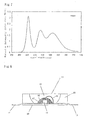
- desirable examples of light-emitting sources include ones for emitting light at wavelengths of 330 to 500 nm, and particularly, ultraviolet (or violet) LED light emitting elements for 330 to 420 nm, or blue LED light emitting elements for 420 to 500 nm.
- Such light emitting elements include ones comprising nitride semiconductor such as GaN, InGaN, or the like, which can be made into light-emitting sources for emitting light at predetermined wavelengths by composition adjustment.
- a lighting instrument for emitting light in a desired color by combiningly using a phosphor having another emission characteristic.
- a lighting instrument for emitting light in a desired color by combiningly using a phosphor having another emission characteristic.
- examples thereof include a combination of: an ultraviolet LED light emitting element of 330 to 420 nm; a blue-aimed phosphor to be excited at the above-mentioned wavelength to thereby emit light at a wavelength between 420 nm inclusive and 480 nm inclusive; a green-aimed phosphor to be similarly excited to thereby emit light at a wavelength between 500 nm inclusive and 550 nm inclusive; and the phosphor of the present invention.
- blue-aimed phosphors and green-aimed phosphors examples include BaMgAl 10 O 17 :Eu and BaMgAl 10 O 17 :Eu, Mn, respectively.
- ultraviolet rays emitted by the LED are irradiated to the phosphors which then emit light in three colors of red, blue, and green, thereby establishing a lighting instrument for emitting white light mixedly including these light.
- Another way includes a combination of: a blue LED light emitting element of 420 to 500 nm; a yellow-aimed phosphor to be excited at the above-mentioned wavelength to thereby emit light at a wavelength between 550 nm inclusive and 600 nm inclusive; and the phosphor of the present invention.
- yellow-aimed phosphors include (Y, Gd) 2 (Al, Ga) 5 O 12 :Ce described in JP-2927279 , ⁇ -sialon:Eu described in JP-A-2002-363554 , and the like.
- Ca- ⁇ -sialon including Eu dissolved therein in a solid state is preferable by virtue of a higher emission luminance.
- blue light emitted by the LED is irradiated to the phosphors which then emit light in two colors of red and yellow, which light is mixed with the blue light by the LED itself, thereby establishing a lighting instrument for emitting light in white or reddish incandescent color.
- Still another way includes a combination of: a blue LED light emitting element of 420 to 500 nm; a green-aimed phosphor to be excited at the above-mentioned wavelength to thereby emit light at a wavelength between 500 nm inclusive and 570 nm inclusive; and the phosphor of the present invention.
- green-aimed phosphors include Y 2 Al 5 O 12 :Ce, ⁇ -sialon:Eu, and the like.
- blue light emitted by the LED is irradiated to the phosphors which then emit light in two colors of red and green, which light is mixed with the blue light by the LED itself, thereby establishing a lighting instrument for emitting white light.
- the image displaying apparatus of the present invention is constituted of at least an excitation source and the phosphor of the present invention, and examples thereof include a vacuum fluorescent display (VFD), field emission display (FED), plasma display panel (PDP), cathode ray tube (CRT), and the like. It has been confirmed that the phosphors of the present invention can each emit light by excitation of vacuum ultraviolet light from 100 to 190 nm, ultraviolet light from 190 to 380 nm, electron beam, and the like, and combining such an excitation source with the phosphor of the present invention enables establishment of such an image displaying apparatus as described above.
- VFD vacuum fluorescent display
- FED field emission display
- PDP plasma display panel
- CRT cathode ray tube
- the crucible containing the mixed powder therein was set in an electric furnace of a black lead resistance heating type. There was conducted a firing operation by firstly bringing the firing environment to vacuum by a diffusion pump, heating from a room temperature up to 800°C at a rate of 500°C/hour, introducing nitrogen at a purity of 99.999vol% at 800°C to achieve a pressure of 1 MPa, elevating the temperature to 1,800°C at a rate of 500°C/hour, and holding for 2 hours at 1,800°C.
- the synthesized compound was pulverized by an agate mortar, and there was conducted a powder X-ray diffraction measurement by K ⁇ line of Cu.
- the resultingly obtained chart is shown in FIG. 2, and there were not detected unreacted Si 3 N 4 , SrO, and the like, and an already reported compound of Si 3 N 4 -SrO type.
- the substance shown in X-ray diffractometry in FIG. 2 was confirmed to be Sr 2 Si 3 O 2 N 4 in a single phase.
- Sr 2 Si 3 O 2 N 4 activated with Eu Used as starting material powders were: a silicon nitride powder having an averaged particle size of 0.5 ⁇ m, an oxygen content of 0.93wt%, and an ⁇ -type content of 92%; a strontium carbonate powder having a specific surface area of 3.3 m 2 /g; and a europium oxide powder.
- the crucible containing the mixed powder therein was set in an electric furnace of a black lead resistance heating type. There was conducted a firing operation by firstly bringing the firing environment to vacuum by a diffusion pump, heating from a room temperature up to 800°C at a rate of 500°C/hour, introducing nitrogen at a purity of 99.999vol% at 800°C to achieve a pressure of 1 MPa, elevating the temperature to 1,800°C at a rate of 500°C/hour, and holding for 2 hours at 1,800°C.
- the obtained fired body was roughly pulverized, and then manually pulverized by a crucible and a mortar both made of silicon nitride sintered body, followed by passage through a sieve of 30 ⁇ m mesh. Measurement of particle size distribution showed an averaged particle size of 10 ⁇ m.
- the synthesized compound was pulverized by an agate mortar, and there was conducted a powder X-ray diffraction measurement by K ⁇ line of Cu.
- the obtained chart was confirmed to represent a crystal having the same crystal structure as an Sr 2 Si 3 O 2 N 4 crystal, and any other crystal phases were not detected.
- This powder was irradiated by a lamp emitting light at a wavelength of 365 nm, thereby confirming that the powder emitted red light.
- the powder was measured by a spectrophotofluorometer to provide an emission spectrum and an excitation spectrum (FIG. 3), thereby resultingly showed that the powder was a phosphor having a peak at 438 nm in the excitation spectrum, and a peak at red light of 624 nm in the emission spectrum based on the excitation of 438 nm.
- the emission intensity at the peak was 0.91 count. Note that the count value has an arbitrary unit, since it varies depending on a measurement device, a measurement condition, and the like.
- starting materials were mutually mixed at mixture compositions listed in Table 2, followed by firing in firing conditions listed in Table 3, as well as subsequent application of heat treatment in conditions listed in Table 3 as required, respectively.
- the inorganic compounds were thus synthesized, by the otherwise same procedures as those in the method for Example 1.
- the powders were each measured by a spectrophotofluorometer to provide an emission spectrum and an excitation spectrum, thereby resultingly obtaining phosphors having peak wavelengths in excitation spectra, peak wavelengths in emission spectra, and peak emission intensities in the emission spectra listed in Table 4, respectively.
- Table 1 shows parameters of designed compositions of Examples 1 through 37, respectively.
- Table 2 shows mixture compositions of starting material powders of Examples 1 through 37, respectively.
- Table 3 shows firing conditions and heat treatment conditions of Examples 1 through 37, respectively.
- Table 4 shows peak wavelengths of excitation spectra, and peak wavelengths and peak intensities of emission spectra of Examples 1 through 37, respectively.
- Table 1 Parameter of Designed Composition Example Eu (M) A (parameter b) Si O N a Mg Ca Sr Ba c d e 1 0.0018 0 0 0.1800 0 0.2727 0.1818 0.3636 2 0.0011 0 0 0.1100 0 0.3333 0.1111 0.4444 3 0.0006 0 0 0.0619 0 0.3750 0.0625 0.5000 4 0.0004 0 0 0.0430 0 0.3913 0.043 0.5217 5 0.0003 0 0 0.330 0 0.4000 0.0333 0.5333 6 0.0003 0 0 0.0268 0 0.4054 0.0270 0.5405 7 0.0002 0 0 0.0225 0 0.4091 0.0227 0.5455 8 0.0002 0 0 0.0171 0 0.4138 0.0172 0.5517 9 0.0002 0
- an inorganic compound Ca 0.95 Eu 0.05 Si 5 ON 8 to be provided by activating a CaSi 6 ON 8 crystal with Eu there were mixed a silicon nitride powder, a calcium carbonate powder, and a europium oxide powder at a ratio of 72.977 mass%, 24.73 mass%, and 2.29 mass%, respectively, followed by firing for 2 hours at 1,800°C in nitrogen at 0.45 MPa, thereby synthesizing a phosphor.
- the synthesis was conducted in the otherwise same procedures as those in the method for Example 1.
- the obtained inorganic compound exhibited the same X-ray diffractometry pattern as the CaSi 6 ON 8 crystal, and was thus confirmed to be an inorganic compound obtained by activating a CaSi 6 ON 8 crystal with Eu.
- the powder was measured by a spectrophotofluorometer to obtain an emission spectrum and an excitation spectrum, thereby resultingly obtaining a phosphor having properties of excitation spectrum and emission spectrum shown in FIG. 10.
- an inorganic compound Sr 0.95 Eu 0.08 Si 5 ON 8 to be provided by activating an SrSi 6 ON 8 crystal with Eu, there were mixed a silicon nitride powder, a strontium carbonate powder, and a europium oxide powder at a ratio of 72.42 mass%:, 25.412 mass, and 2.168 mass%, respectively, followed by firing for 2 hours at 1,800°C in nitrogen at 0.45 MPa, thereby synthesizing a phosphor.
- the synthesis was conducted in the otherwise same procedures as those in the method for Example 1.
- the obtained inorganic compound exhibited the same X-ray diffractometry pattern as the SrSi 6 ON 8 crystal, and was thus confirmed to be an inorganic compound obtained by activating an SrSi 6 ON 8 crystal with Eu.
- the powder was measured by a spectrophotofluorometer to obtain an emission spectrum and an excitation spectrum, thereby resultingly obtaining a phosphor having properties of excitation spectrum and emission spectrum shown in FIG. 11.
- an inorganic compound Ba 0.95 Eu 0.05 Si 5 ON 8 to be provided by activating a BaSi 6 ON 8 crystal with Eu there were mixed a silicon nitride powder, a calcium carbonate powder, and a europium oxide powder at a ratio of 64.555 mass%, 33.513 mass%, and 1.932 mass%, respectively, followed by firing for 2 hours at 1,800°C in nitrogen at 0.45 MPa, thereby synthesizing a phosphor.
- the synthesis was conducted in the otherwise same procedures as those in the method for Example 1.
- the obtained inorganic compound exhibited the same X-ray diffractometry pattern as the BaSi 6 ON 8 crystal, and was thus confirmed to be an inorganic compound obtained by activating a BaSi 6 ON 8 crystal with Eu.
- the powder was measured by a spectrophotofluorometer to obtain an emission spectrum and an excitation spectrum, thereby resultingly obtaining a phosphor having properties of excitation spectrum and emission spectrum shown in FIG. 12.
- a green-aimed phosphor to be used for a lighting instrument there was synthesized a phosphor, i.e., ⁇ -sialon : Eu comprising ⁇ -sialon containing Eu dissolved therein in a solid state.
- FIG. 6 There was fabricated a so-called bullet-type white light emitting diode lamp (1) shown in FIG. 6. It included two lead wires (2, 3), one (2) of which had a depression having a blue light emitting diode element (4) placed therein.
- the blue light emitting diode element (4) had a lower electrode electrically connected to a bottom surface of the depression by an electroconductive paste, and an upper electrode electrically connected to the other lead wire (3) via thin gold line (5).
- a phosphor obtained by mixing a first phosphor and a second phosphor was used.
- the first phosphor was the ⁇ -sialon:Eu synthesized in this Example
- the second phosphor was one synthesized in Example 22.
- Mounted near the light emitting diode element (4) was the phosphor (7) obtained by mixing the first phosphor and the second phosphor and which was dispersed in a resin.
- the phosphors were dispersed in a first resin (6) which was transparent and which covered the whole of the blue light emitting diode element (4).
- a second transparent resin (8) Encapsulated in a second transparent resin (8) were the tip end of the lead wire including the depression, the blue light emitting diode element, and the first resin including the phosphors dispersed therein.
- the second transparent resin (8) was in a substantially column shape as a whole, and had a tip end portion of a curved surface in a lens shape, which is typically called a bullet type.
- the mixing ratio between the first phosphor powder and second phosphor powder was set to be 5:1, this mixed powder was blended into an epoxy resin at a concentration of 35wt%, and the resultant resin was dropped at an appropriate amount by a dispenser, thereby forming the first resin (6) including the mixed phosphor (7) dispersed therein.
- FIG. 7 shows an emission spectrum of this white light emitting diode.
- the blue light emitting diode element (4) is die-bonded by an electroconductive paste onto the element placement depression of one (2) of the paired lead wires, to thereby electrically connect the lead wire to the lower electrode of the blue light emitting diode element and to fix the blue light emitting diode element (4).
- the upper electrode of the blue light emitting diode element (4) is die bonded to the other of lead wires, thereby electrically connecting them to each other.
- the first green-aimed phosphor powder and the second red-aimed phosphor powder are the first green-aimed phosphor powder and the second red-aimed phosphor powder, and this mixed phosphor powder is mixed into an epoxy resin at a concentration of 35wt%.
- the resultant resin is coated in an appropriate amount onto the depression by a dispenser to cover the blue light emitting diode element, and then cured to form the first resin (6) .
- the tip end of the lead wire including the depression, the blue light emitting diode element, and the first resin including the phosphors dispersed therein are wholly encapsulated in the second resin by a casting method.
- the same epoxy resin was used for the first resin and second resin in this Example, it is possible to adopt another resin such as a silicone resin, or a transparent material such as glass. It is desirable to select a material which is less in degradation due to ultraviolet light.
- a white alumina ceramic substrate (29) having a higher reflectivity to visible light, and two lead wires (22, 23) fixed thereto, and the lead wires each included one end located at substantially the center position of the substrate, and the other end drawn out to the exterior to form an electrode to be soldered to an electric substrate upon mounting thereto.
- a blue light emitting diode element (24) Placed onto and fixed to the one end of one (22) of the lead wires, was a blue light emitting diode element (24) so as to be located at the central portion of the substrate.
- the blue light emitting diode element (29) had a lower electrode electrically connected to the lead wire thereunder by an electroconductive paste, and an upper electrode electrically connected to the other lead wire (23) by a thin gold line (25).
- a resin including a phosphor (27) which was dispersed therein and which was obtained by mixing a first resin and a second phosphor with each other.
- the first resin (26) including the phosphor dispersed therein was transparent and covered the whole of the blue light emitting diode element (24).
- a wall surface member (30) in a shape having a hole at a central portion As shown in FIG. 8, the wall surface member (30) had its central portion acting as the hole for accommodating therein the blue light emitting diode element (24) and the first resin (26) including the phosphor (27) dispersed therein, and had a portion which was faced to the center and which was formed into an inclined surface.
- This inclined surface was a reflective surface for forwardly directing light-beams, and had a curved shape to be determined in consideration of the reflected directions of light-beams. Further, at least the surface which constituted the reflective surface, was formed into a surface which was white in color or had metallic luster and which had a higher reflectivity to visible light.
- the wall surface member was constituted of a white silicone resin (30). While the hole of the wall surface member at its central portion constitutes a depression as a final shape of the chip-type light emitting diode lamp, the depression is filled with a second transparent resin (28) in a manner to encapsulate all the blue light emitting diode element (24) and the first resin (26) including the phosphor (27) dispersed therein.
- Adopted as the first resin (26) and second resin (28) in this Example was the same epoxy resin.
- the mixing ratio between the first phosphor and second phosphor, the achieved chromaticity, and the like were substantially the same as those of the first configuration.
- the producing procedure was substantially the same as that of the first configuration, except for a step for fixing the lead wires (22, 23) and the wall surface member (30) to the alumina ceramic substrate (29).
- a lighting apparatus having a configuration different from the above. This is provided based on the lighting apparatus of FIG. 6, in a structure including: a blue LED of 450 nm as a light emitting element; and a Phosphor dispersion resin layer covered on the blue LED, the resin layer being provided by dispersing, in a layer of resin, the phosphor of Example 1 of the present invention and a yellow-aimed phosphor of Ca-a-sialon:Eu having a composition of Ca 0.75 Eu 0.25 Si 8.625 Al 3.375 O 1.125 N 14.875 .
- a lighting apparatus having another configuration different from the above. This is provided based on the lighting apparatus of FIG. 6, in a structure including: an ultraviolet LED of 380 nm as a light emitting element; and a Phosphor dispersion resin layer covered on the ultraviolet LED, the resin layer being provided by dispersing, in a layer of resin, the phosphor of Example 1 of the present invention, a blue-aimed phosphor (BaMgAl 10 O 17 :Eu), and a green-aimed phosphor (BaMgAl 10 O 17 :Eu, Mn).
- a blue-aimed phosphor BaMgAl 10 O 17 :Eu
- a green-aimed phosphor BaMgAl 10 O 17 :Eu, Mn
- FIG. 9 is a principle schematic view of a plasma display panel as an image displaying apparatus.
- the apparatus includes cells 34, 35, and 36 having inner surfaces coated with the red-aimed phosphor of Example 1 of the present invention, a green-aimed phosphor (Zn 2 SiO 4 :Mn) and a blue-aimed phosphor (BaMgAl 10 O 17 :Eu), respectively.
- the nitride phosphors of the present invention exhibit emission at longer wavelengths than those by conventional sialon phosphors and oxynitride phosphors, are excellent as red-aimed phosphors, and are less in luminance deterioration even upon exposure to excitation sources, thereby serving as nitride phosphors preferably usable for VFD, FED, PDP, CRT, white LED, and the like.
- the nitride phosphors of the present invention can be expected to be utilized to a great extent in material design of various display devices, thereby contributing to development of the industry.
Abstract
a composition on a pseudo-ternary phase diagram including AO (A is one kind or two or more kinds of element(s) selected from Mg, Ca, Sr, and Ba; and AO is oxide of A), Si3N4, and SiO2 as end members, respectively, and satisfying all of the following conditions:
in a composition formula, pAO-qSi3N4-rSiO2 (p+q+r=1),
and
and
at least a metallic element M (M is one kind or two or more kinds of element(s) selected from Mn, Ce, Nd, Sm, Eu, Tb, Dy, Ho, Er, Tm, and Yb) dissolved, in a solid state, in the composition.
Description
- The present invention relates to a phosphor mainly including an inorganic compound and a production method and usage thereof. More particularly, the usage relates to a light emitting instrument for a lighting instrument and for an image displaying apparatus, utilizing the nature possessed by the phosphor, i.e., the property to emit fluorescence at long wavelengths between 570 nm and 700 nm.
- Phosphors have been utilized for vacuum fluorescent displays (VFD), field emission displays (FED), plasma display panels (PDP), cathode ray tubes (CRT), white light emitting diodes (LED), and the like. In all these usages, it is required to supply an energy to an applicable phosphor to thereby excite it so as to cause it to emit light, and the phosphor is excited by an excitation source having high energy such as vacuum ultraviolet light, ultraviolet light, electron beam, blue light, or the like, such that the phosphor is caused to emit visible light.
- However, since phosphors are exposed to the aforementioned excitation sources to resultingly cause a problem of deteriorated luminance during long-term usage, thereby necessitating a phosphor which is free of luminance deterioration. As such, there has been proposed a sialon phosphor as a phosphor exhibiting less luminance deterioration, instead of the conventional silicate phosphor, phosphate phosphor, aluminate phosphor, sulfide phosphor, and the like.
- The sialon phosphor is produced by a production process as generally described below. Firstly, there are mutually mixed silicon nitride (Si3N4), aluminum nitride (AlN), calcium carbonate (CaCO3), and europium oxide (Eu2O3) at a predetermined molar ratio, followed by holding for 1 hour at a temperature of 1,700°C in nitrogen at 1 atm (0.1 MPa), and firing by hot pressing for production (see
Patent Document 1, for example). - It has been reported that α-sialon obtained by the process and activated by Eu ion is established into a phosphor which is excited by blue light at 450 to 500 nm and caused to emit yellow light at 550 to 600 nm. However, there have been demanded not only the phosphor which emits yellow light but also phosphors which emit orange light and red light, respectively, for usages such as white LED and plasma display each having an ultraviolet LED as an excitation source. Further, there have been demanded phosphors which emit orange light, red light, and the like, respectively, in a white LED having a blue LED as an excitation source, for an improved color rendering property.
- As a phosphor which emits red light, there has been reported an inorganic substance (Ba2-xEuxSi5N8 ; where x=0.14 to 1.16) obtained by activating a Ba2Si5N8 crystal with Eu, in a scientific literature (see Non-patent Document 1) prior to filing of the present application. There has been further reported a phosphor including, as a host material, a ternary nitride of alkali metals and silicon at various compositions, MxSiyNz (M= Ca, Sr, Ba, Zn; where x, y, and z take various values, respectively), in the second chapter of a publication "On new rare-earth doped M-Si-Al-O-N materials" (see Non-patent Document 2). Similarly, there has been reported MxSiyNz:Eu (M= Ca, Sr, Ba, Zn; where z=2/3x+4/3y), in
U.S. Patent No. 6,682,663 (Patent Document 2). - As other sialon phosphors, nitride phosphors, and oxynitride phosphors, there have been described phosphors including, as host crystals, MSi3N5, M2Si4N7, M4Si6N11, M9Si11N23, M16Si15O6N32, M13Si18Al12O18N36, MSi5Al2ON9, and M3Si5AlON10 (where M is Ba, Ca, Sr, or rare earth element) activated with Eu, Ce, or the like in
JP-A-2003-206481 U.S. Patent No. 6,670,748 (Patent Document 4), and there have been described therein a phosphor which emits red light and an LED lighting unit utilizing the phosphor. - Among them, SrSiAl2O3N2:Eu2+ and Sr2Si4AlON7:Eu2+ have been known as compounds based on EuaSrbSicAldOeNf. Further, there has been reported a phosphor obtained by activating an Sr2Si5N8 or SrSi7N10 crystal with Ce, in
JP-A-2002-322474 - In
JP-A-2003-321675 - In turn, there has been reported a phosphor configured with various L elements, M elements, and Z elements, as an LxMyN(2/3x+4/3y):Z phosphor, in
JP-A-2003-277746 JP-A-2004-10786 - Although the phosphors represented by those of the
aforementioned Patent Documents 2 through 7 have been reported as ones including various different crystal phases as host materials while providing known phosphors for emitting red light, emission luminances of red light have been insufficient insofar as based on excitation by blue visible light. Further, the phosphors have been chemically unstable depending on compositions, thereby exhibiting a problem of durability. Moreover, there have been adopted metals such as Ca, Sr, and the like, or nitride, as starting materials, so that the applicable powder is required to be mixedly obtained in a state where air is to be shut off, thereby exhibiting a problem of productivity. - As the related art of lighting apparatus, there has been known a white light emitting diode based on a combination of a blue light emitting diode element with a blue-light absorbing/yellow-light emitting phosphor, which has been practiced in various lighting usages. Representative examples thereof include those described in
JP-2900928 JP-2927279 JP-3364229 - The phosphors, which are particularly frequently utilized in these light emitting diodes, are yttrium/aluminum/garnet based phosphors represented by a general formula (Y, Gd)3(Al, Ga)5O12:Ce3+.
- However, the white light emitting diode comprising the blue light emitting diode element and the yttrium/aluminum/garnet based phosphor has a feature to emit bluish white light due to lack of a red component, thereby problematically exhibiting deviation in a color rendering property.
- Under such circumstances, there has been investigated a white light emitting diode including two kinds of mixed and dispersed phosphors, such that a red component lacking in case of a yttrium/aluminum/garnet based phosphor is compensated for by an additional red-aimed phosphor. Examples of such light emitting diodes include
JP-A-10-163535 JP-A-2003-321675 JP-A-10-163535 JP-A-2003-321675 - Referenced Literature/Publication:
- Non-patent Document 1: H. A. Hoppe, and four others, "Journal of Physics and Chemistry of Solids", 2000, No. 61, pp. 2001-2006
- Non-patent Document 2: "On new rare-earth doped M-Si-Al-O-N meterials", written by J. W. H. van Krevel, TU Eindhoven 2000, ISBN 90-386-2711-4
- Patent Document 1:
JP-A-2002-363554 - Patent Document 2:
U.S. Patent No. 6,682,663 - Patent Document 3:
JP-A-2003-206481 - Patent Document 4:
U.S. Patent No. 6,670,748 - Patent Document 5:
JP-A-2002-322474 - Patent Document 6:
JP-A-2003-321675 - Patent Document 7:
JP-A-2003-277746 - Patent Document 8:
JP-A-2004-10786 - Patent Document 9:
JP-2900928 - Patent Document 10:
JP-2927279 - Patent Document 11:
JP-3364229 - Patent Document 12:
JP-A-10-163535 - The present invention intends to satisfy such a demand, and has an object to provide a chemically stabilized inorganic phosphor, among oxynitride phosphors including alkaline earths, which oxynitride phosphor emits orange or red light at longer wavelengths and at higher luminance than conventional sialon phosphors activated by rare earths.
- It is another object of the present invention to provide a production method therefor suitable for industrial production, by adopting starting materials which are stable in the atmosphere. It is still another object of the present invention to provide a light emitting instrument utilizing such a phosphor, for a lighting instrument excellent in color rendering property and for an image displaying apparatus excellent in durability.
- Under these circumstances, the present inventors have specifically investigated phosphors including, as host materials, inorganic multi-component nitride crystals including (i) divalent alkaline earth elements (A) such as Mg, Ca, Sr, and Ba, and (ii) Si, both as main metallic elements, and have found that those phosphors allow for preparation of powders therefor in the atmosphere and emit fluorescence at higher luminance than the conventionally reported ones including, as host crystals, nitrides, oxynitrides, and the like, which phosphors by the present inventors include, as host materials, inorganic crystals having a specific composition based on Si3N4-SiO2-AO, a specific composition based on Si2N2O-AO, or a specific composition based on Si3N4-AO, which is activated by photoactive metals such as Mn, Ce, Nd, Sm, Eu, Tb, Dy, Ho, Er, Tm, Yb, and the like.
- Namely, the present inventors have earnestly and repeatedly investigated inorganic compounds mainly including oxynitrides containing: an M element (M is one kind or two or more kinds of element(s) selected from Mn, Ce, Pr, Nd, Sm, Eu, Gd, Tb, Dy, Ho, Er, Tm, and Yb) to be matured into a light emitting ion; a divalent A element (A is one kind or two or more kinds of element(s) selected from Mg, Ca, Sr, and Ba); Si; nitrogen; and oxygen; and have found that there can be obtained phosphors which emit orange or red light at higher luminance, each derived from a crystal of a specific composition represented by MaAbSicOdNe, and particularly based on an inorganic compound including A2Si3O2N4 crystal, A2Si3O2N4 solid solution crystal, A3Si3O3N4 crystal, A3Si3O3N4 solid solution crystal, A3Si2O4N2 crystal, or A3Si2O4N2 solid solution crystal, which is activated by an M element such as Eu.
- Further, the present inventors have found that adoption of this phosphor allows for obtainment of a white light emitting diode having a higher light-emission efficiency and being excellent in color rendering property with a rich red component, and an image displaying apparatus for exhibiting brilliant red color.
- The present inventors have also found that the host crystal of the phosphor according to the present invention includes a specific crystal represented by MaAbSicOdNe as a host material to thereby achieve emission at a luminance which has never been provided up to now, unlike the ternary nitrides including divalent and tetravalent elements as represented by the conventionally reported LxMyN(2/3x+4/3y). Further, the present invention resides in a novel phosphor including, as a host material, a crystal having a composition and a crystal structure which are fully different from those of M13Si18Al12O18N36, MSi5Al2ON9, M3Si5AlON10 (M is Ca, Ba, Sr, or the like) , SrSiAl2O3N2: Eu2+, Sr2Si4AlON7:Eu2+ conventionally reported in the
Patent Documents 3, 4, and the like, and the sialon such as Ca1.47Eu0.03Si9Al3N16 described in the eleventh chapter of the Non-patentDocument 2. - Generally, phosphors including inorganic host crystals activated with Mn or rare earth element as an emission center element M, exhibit light emission colors and luminances which vary depending on electronic states around the M element. For example, it has been reported that change of host crystals in phosphors each including Eu as an emission center leads to emission in blue, green, yellow, or red color.
- Namely, even phosphors having similar compositions exhibit fully different light emission colors and luminances when crystal structures of the host materials or atom positions in the crystal structures for introducing M thereinto are changed, so that such phosphors are regarded as ones different from one another. The present invention has devised, as host materials, crystals which are fully different from the conventionally reported compositions of nitrides, oxynitrides, sialons, and the like, and any phosphors including such crystals as host materials have been never reported in the conventional.
- Moreover, the phosphors including the compositions of the present invention as host materials, have luminances higher than those phosphors including conventional crystals as host materials, and exhibit red light emission at specific compositions.
- The present inventors have earnestly and repetitively conducted investigation in view of the above-described actual situation, and have succeeded in providing phosphors which exhibit emission phenomena at higher luminances over specific wavelength ranges, respectively, by achieving configurations recited in the following items (1) through (29).
- Further, the present inventors have succeeded in producing phosphors having excellent emission characteristics, by adopting the methods of items (30) through (45).
- Moreover, the present inventors have also succeeded in providing a lighting instrument and an image displaying apparatus having excellent properties by using the phosphor and achieving configurations recited in items (46) through (55), and the above configurations are recited in the following items (1) through (55).
- (1) A phosphor, characterized in that the phosphor includes, as a main component, an inorganic compound comprising:
- a composition on a pseudo-ternary phase diagram including AO (A is one kind or two or more kinds of element(s) selected from Mg, Ca, Sr, and Ba; and AO is oxide of A), Si3N4, and SiO2 as end members, respectively, and satisfying all of the following conditions:
in a composition formula, pAO-qSi3N4-rSiO2 (p+q+r=1),

and
and
at least a metallic element M (M is one kind or two or more kinds of element(s) selected from Mn, Ce, Nd, Sm, Eu, Tb, Dy, Ho, Er, Tm, and Yb) dissolved, in a solid state, in the composition.
- a composition on a pseudo-ternary phase diagram including AO (A is one kind or two or more kinds of element(s) selected from Mg, Ca, Sr, and Ba; and AO is oxide of A), Si3N4, and SiO2 as end members, respectively, and satisfying all of the following conditions:
- (2) The phosphor of item (1), characterized in that the composition on the pseudo-ternary phase diagram including AO, Si3N4, and SiO2 as end members, respectively, is in a crystal phase.
- (3) The phosphor of item (1) or (2), characterized in that the phosphor includes at least the metallic element M (M is one kind or two or more kinds of element(s) selected from Mn, Ce, Nd, Sm, Eu, Tb, Dy, Ho, Er, Tm, and Yb), a metallic element A, Si, oxygen, and nitrogen; and
that the ratio among the elements M, A, O, Si, and N is represented by a composition formula MaAbSicOdNe (a+b+c+d+e=l) which satisfies all of the following conditions:


and
- (4) The phosphor of item (3), characterized in that f=1 and g=1.
- (5) The phosphor of item (3) or (4), characterized in that c≤3b.
- (6) The phosphor of any one of items (1) through (5), characterized in that the phosphor includes, as the main component, an inorganic compound comprising:
a crystal represented by a composition formula hSi3N4+iAO ("h" and "i" are between 0 inclusive and 1 inclusive, and 0.2≤i / (h+i) ≤0.95), or a solid solution of the crystal; and
the M element for activating the crystal or the solid solution of the crystal. - (7) The phosphor of any one of items (1) through (6), characterized in that the phosphor includes, as the main component, an inorganic compound comprising:
- an A2Si3O2N4 crystal, or a solid solution crystal thereof; and
- the M element for activating the crystal or solid solution crystal.
- (8) The phosphor of item (7), characterized in that the solid solution crystal of A2Si3O2N4 is A2Si3-xAlxO2+xN4-x (0≤x≤0.5).
- (9) The phosphor of any one of items (1) through (6), characterized in that the phosphor includes, as the main component, an inorganic compound comprising:
- an A3Si3O3N4 crystal, or a solid solution crystal thereof; and
- the M element for activating the crystal or solid solution crystal.
- (10) The phosphor of item (9), characterized in that the solid solution crystal of A3Si3O3N4 is A3Si3-xAlxO3+xN4-x (0≤x≤0.5).
- (11) The phosphor of item (1) or (2), characterized in that the phosphor includes at least the metallic element M (M is one kind or two or more kinds of element(s) selected from Mn, Ce, Nd, Sm, Eu, Tb, Dy, Ho, Er, Tm, and Yb), the metallic element A, Si, oxygen, and nitrogen; and
that the ratio among the elements M, A, Si, O, and N is represented by a composition formula MaAbSicOdNe (a+b+c+d+e=1), which satisfies all of the following conditions:


and
- (12) The phosphor of item (11), characterized in that f=1 and g=1.
- (13) The phosphor of item (11) or (12), characterized in that c≤b.
- (14) The phosphor of any one of items (1), (2), and (11) through (13), characterized in that the phosphor includes, as the main component, an inorganic compound comprising:
a crystal represented by a composition formula hSi2N2O+iAO ("h" and "i" are between 0 inclusive and 1 inclusive, and 0.2≤i/(h+i)≤0.95), or a solid solution of the crystal; and
the M element for activating the crystal or the solid solution of the crystal. - (15) The phosphor of any one of items (1), (2), and (11) through (14), characterized in that the phosphor includes, as the main component, an inorganic compound comprising:
- an A3Si2O4N2 crystal, or a solid solution crystal thereof; and
- the M element for activating the crystal or solid solution crystal.
- (16) The phosphor of item (15), characterized in that the solid solution crystal of A3Si2O4N2 is A3Si2-xAlxO4+xN2-x (0≤x≤0.5) .
- (17) The phosphor of any one of items (1) through (16), characterized in that the phosphor includes, as the main component, an inorganic compound comprising:
an A3Si3-yO3+yN4-2y crystal (0≤y≤1.8), or a solid solution crystal thereof; and
the M element for activating the crystal or solid solution crystal. - (18) The phosphor of any one of items (1) through (17), characterized in that the phosphor includes at least Eu in M.
- (19) The phosphor of any one of items (1) through (18), characterized in that the phosphor includes at least Sr in A.
- (20) The phosphor of any one of items (1) through (19), characterized in that M is Eu and A is Sr.
- (21) The phosphor of any one of items (1) through (20), characterized in that A is a mixture of Ca and Sr.
- (22) The phosphor of any one of items (1) through (20), characterized in that A is a mixture of Ba and Sr.
- (23) The phosphor of any one of items (1) through (22), characterized in that the phosphor emits orange or red fluorescence at a wavelength between 570 nm inclusive and 700 nm inclusive, by irradiation of an excitation source comprising ultraviolet light, visible light, or electron beam.
- (24) The phosphor of any one of items (1) through (23), characterized in that the phosphor emits fluorescence having a "y" value between 0.44 inclusive and 0.73 inclusive in terms of CIE chromaticity representation.
- (25) The phosphor of any one of items (1) through (24), characterized in that the inorganic compound is a powder having an averaged particle size between 0.1 µm inclusive and 50 µm inclusive.
- (26) A phosphor characterized in that the phosphor is constituted of a mixture of the inorganic compound of any one of items (1) through (25) and an additional crystal phase or amorphous phase; and
that the inorganic compound of any one of items (1) through (25) is included at a content of 10 mass% or more. - (27) The phosphor of item (26), characterized in that the content of inorganic compound of any one of items (1) through (25) is 50 mass% or more.
- (28) The phosphor of item (26) or (27), characterized in that the additional crystal phase or amorphous phase is an inorganic substance having electroconductivity.
- (29) The phosphor of item (28), characterized in that the inorganic substance having electroconductivity is oxide, oxynitride, nitride, or a mixture thereof including one kind or two or more kinds of element(s) selected from Zn, Ga, In, and Sn.
- (30) A production method of the phosphor of any one of items (1) through (29), characterized in that the method comprises the step of:
- firing a starting material mixture in a nitrogen atmosphere at a temperature range between 1,200°C inclusive and 2,200°C inclusive,
- (31) The production method of the phosphor of item (30), characterized in that the metallic compound mixture is a mixture of: a metal, oxide, carbonate, nitride, fluoride, chloride, or oxynitride of M; a metal, oxide, carbonate, nitride, fluoride, chloride, or oxynitride of A; silicon nitride; silicon oxide as required; aluminum nitride as required; and aluminum oxide as required.
- (32) The production method of the phosphor of item (30) or (31), characterized in that the metallic compound mixture is obtained by mutually mixing; europium oxide; oxide or carbonate of A; silicon nitride; and silicon oxide as required; at a molar composition ratio (where the molar amount of A is calculated as oxide, in case of adopting carbonate of A) represented by:

where p+q+r+s=1,

and
- (33) The production method of the phosphor of item (32), characterized in that r=0.
- (34) The production method of the phosphor of item (32), characterized in that q=r.
- (35) The production method of the phosphor of any one of items (30) through (34), characterized in that the method further comprises the step of:
- adding a flux compound for generating a liquid phase at the firing temperature, into the metallic compound mixture.
- (36) The production method of the phosphor of item (35), characterized in that the flux compound is a compound selected from fluoride, chloride, and borate of the A element.
- (37) The production method of the phosphor of any one of items (30) through (36), characterized in that the nitrogen atmosphere is a gas atmosphere at a pressure in a range between 0.1 MPa inclusive and 100 MPa inclusive.
- (38) The production method of the phosphor of any one of items (30) through (37), characterized in that the method further comprises the step of:
- firing the metallic compounds each in a form of powder or aggregation, after filling the metallic compounds in a container in a state where the metallic compounds are held at a filling ratio exhibiting a relative bulk density of 40% or less.
- (39) The production method of the phosphor of item (38), characterized in that the container is made of boron nitride.
- (40) The production method of the phosphor of any one of items (30) through (39), characterized in that the sintering step is conducted not by means of hot-press, but exclusively by means of ordinary pressure sintering or gas pressure sintering.
- (41) The production method of the phosphor of any one of items (30) through (40), characterized in that the method further comprises the step of:
- adjusting the synthesized phosphor powder in granularity, to cause the same to have an averaged particle size between 50 nm inclusive and 50 µm inclusive, by a single or multiple procedures selected from pulverization, classification, and acid treatment.
- (42) The production method of the phosphor of any one of items (30) through (41), characterized in that the method further comprises the step of:
- heat treating the phosphor powder after firing, the phosphor powder after pulverization treatment, or the phosphor powder after granularity adjustment, at a temperature between 1,000°C inclusive and the firing temperature inclusive.
- (43) The production method of the phosphor of any one of items (30) through (42), characterized in that the method further comprises the step of:
- washing the product after firing by a solvent comprising water or an acidic water solution, to thereby decrease contents of a glass phase, second phase, flux component phase, or impurity phase included in the product.
- (44) The production method of the phosphor of item (43), characterized in that the acid comprises a single or a combination of sulfuric acid, hydrochloric acid, nitric acid, hydrofluoric acid, and organic acids.
- (45) The production method of the phosphor of item (43) or (44), characterized in that the acid is a mixture of hydrofluoric acid and sulfuric acid.
- (46) A lighting instrument constituted of at least a light-emitting source and a phosphor, characterized in that the phosphor of at least one of items (1) through (29) is used.
- (47) The lighting instrument of item (46), characterized in that the light-emitting source is a light emitting diode (LED), laser diode, or organic EL light emitting element for emitting light at a wavelength of 330 to 500 nm.
- (48) The lighting instrument of item (46) or (47), characterized in that the light-emitting source is an LED for emitting light at a wavelength between 330 and 420 nm; and
that the constituent phosphor is provided by adopting: the phosphor of any one of items (1) through (29); a blue-aimed phosphor for emitting light between 420 nm inclusive and 500 nm inclusive by pump light between 330 and 420 nm; and a green-aimed phosphor for emitting light between 500 nm inclusive and 570 nm inclusive by pump light between 330 and 420 nm; so that the constituent phosphor emits white light mixedly including red light, green light, and blue light. - (49) The lighting instrument of item (46) or (47), characterized in that the light-emitting source is an LED for emitting light at a wavelength between 420 and 500 nm; and
that the constituent phosphor is provided by adopting: the phosphor of any one of items (1) through (29); and a green-aimed phosphor for emitting light between 500 nm inclusive and 570 nm inclusive by pump light between 420 and 500 nm; so that the constituent phosphor emits white light. - (50) The lighting instrument of item (46) or (47), characterized in that the light-emitting source is an LED for emitting light at a wavelength between 420 and 500 nm; and
that the constituent phosphor is provided by adopting: the phosphor of any one of items (1) through (29); and a yellow-aimed phosphor for emitting light between 550 nm inclusive and 600 nm inclusive by pump light between 420 and 500 nm; so that the constituent phosphor emits white light. - (51) The lighting instrument of item (50), characterized in that the yellow-aimed phosphor is Ca-α-sialon including Eu dissolved therein in a solid state.
- (52) The lighting instrument of item (48) or (49), characterized in that the green-aimed phosphor is β-sialon including Eu dissolved therein in a solid state.
- (53) An image displaying apparatus constituted of at least an excitation source and a phosphor, characterized in that the phosphor of at least one of items (1) through (29) is used.
- (54) The image displaying apparatus of item (53),
characterized in that the excitation source is electron beam, electric field, vacuum ultraviolet light, or ultraviolet light. - (55) The image displaying apparatus of item (53) or (54), characterized in that the image displaying apparatus is a vacuum fluorescent display (VFD), field emission display (FED), plasma display panel (PDP), or cathode ray tube (CRT).
- The phosphors of the present invention each include, as a main component: a crystal of a specific composition represented by MaAbSicOdNe including a divalent alkaline earth element, Si, oxygen, and nitrogen; and particularly include an inorganic compound as a main component including, as host crystals, A2Si3O2N4 crystal, A2Si3O2N4 solid solution crystal, A3Si3O3N4 crystal, A3Si3O3N4 solid solution crystal, A3Si2O4N2 crystal, or A3Si2O4N2 solid solution crystal, which is activated by an M element such as Eu; so that the phosphors of the present invention exhibit emission at longer wavelengths than those by conventional sialon phosphors and oxynitride phosphors, and the like, and are excellent as phosphors for emission in orange, red, and the like. Such compositions can be synthesized by using, as starting materials, Si3N4, SiO2, MO (oxide of M), and AO (oxide of A) or ACO3 (carbonate of A) which are stable in air, and thus the compositions are excellent in productivity. Further, the compositions are excellent in chemical stability, thereby providing useful phosphors to be preferably used for VFD, FED, PDP, CRT, white LED, and the like without luminance deterioration even when exposed to excitation sources.
-
- FIG. is a pseudo-ternary phase diagram including AO, SiO2, and Si3N4 as end members, respectively.
- FIG. 2 is an X-ray diffractometry chart of an Sr2Si3O2N4 crystal.
- FIG. 3 is a graph showing an emission spectrum and an excitation spectrum of a phosphor (Example 1).
- FIG. 4 is a graph showing an emission spectrum and an excitation spectrum of a phosphor (Example 22).
- FIG. 5 is a graph showing an emission spectrum and an excitation spectrum of β-sialon:Eu green-aimed phosphor.
- FIG. 6 is a schematic view of a lighting instrument (LED lighting instrument) according to the present invention.
- FIG. 7 is a graph showing an emission spectrum of the lighting instrument.
- FIG. 8 is a schematic view of a lighting instrument (LED lighting instrument) according to the present invention.
- FIG. 9 is a schematic view of an image displaying apparatus (plasma display panel) according to the present invention.
- FIG. 10 is a graph showing an emission spectrum and an excitation spectrum of a phosphor (Example 38).
- FIG. 11 is a graph showing an emission spectrum and an excitation spectrum of a phosphor (Example 39).
- FIG. 12 is a graph showing an emission spectrum and an excitation spectrum of a phosphor (Example 40).
-
- 1
- bullet type light emitting diode lamp
- 2, 3
- lead wire
- 4
- light emitting diode element
- 5
- bonding wire
- 6, 8
- resin
- 7
- phosphor
- 11
- chip-type white light emitting diode lamp to be mounted on substrate
- 12, 13
- lead wire
- 14
- light emitting diode element
- 15
- bonding wire
- 16, 18
- resin
- 17
- phosphor
- 19
- alumina ceramic substrate
- 20
- side member
- 31
- red-aimed phosphor
- 32
- green-aimed phosphor
- 33
- blue-aimed phosphor
- 34, 35, 36
- ultraviolet emission cell
- 37, 38, 39, 40
- electrode
- 41, 42
- dielectric layer
- 43
- protection layer
- 44, 45
- glass substrate
- The present invention will be described in detail based on Examples and drawings.
- Phosphors of the present invention are each a composition containing at least an activation element M, a divalent alkaline earth element A, nitrogen, oxygen, and Si. Examples of representative constituent elements include: as M, one kind or two or more kinds of element(s) selected from Mn, Ce, Pr, Nd, Sm, Eu, Gd, Tb, Dy, Ho, Er, Tm, and Yb; and as A, one kind or two or more kinds of element(s) selected from Mg, Ca, Sr, and Ba. The phosphors each include, as a main component, an inorganic compound which is constituted of the above listed elements and which comprises:
- a composition on a pseudo-ternary phase diagram including AO (AO is oxide of A), Si3N4, and SiO2 as end members, respectively, and satisfying all of the following conditions:
in a composition formula, pAO-qSi3N4-rSiOz (p+q+r=1),

and
and
at least a metallic element M (M is one kind or two or more kinds of element(s) selected from Mn, Ce, Nd, Sm, Eu, Tb, Dy, Ho, Er, Tm, and Yb) dissolved, in a solid state, in the composition. - Here, the pseudo-ternary phase diagram including AO, Si3N4, and SiO2 as end members, is a representation of compositions including AO, Si3N4, and SiO2 at apexes of a triangle as shown in FIG. 1, where the conditions (1), (2), and (3) correspond to compositions within a quadrilateral surrounded by
points - The phosphors of the present invention each has a composition represented by a composition formula MaAbSicOdNe (a+b+c+d+e=1), and the "a" value indicating an adding amount of the photoactive M element is selected from values satisfying the following condition:

"a" values smaller than 0.00001 lead to a smaller number of elements contributing to light emission, thereby deteriorating an emission intensity. When larger than 0.03, there is caused concentration quenching due to interference among M elements, thereby deteriorating an emission intensity. Particularly, the range of 0.0005 to 0.01 is desirable, by virtue of specifically higher emission intensities then. - Among the inorganic compounds of the present invention, examples of compositions exhibiting specifically higher emission intensities include compositions satisfying the following conditions:


and
- These compositions will be each called a "Si3N4AO type" hereinafter.
- When f=1 and g=1, the composition formula represents a composition hSi3N4+iAO, which is given along a line connecting between Si3N4 and AO on the pseudo-ternary phase diagram including AO, Si3N4, and SiO2 as end members. Here, hSi3N4+iAO represents a composition where Si3N4 and AO are mutually mixed at a molar ratio of h:i. The "f" value and "g" value indicate a discrepancy from hSi3N4+iAO which is an ideal value of the composition, and the values are preferably close to f=1 and g=1 When one of "f" value and "g" value is smaller than 0.8 or larger than 1.25, there are caused products other than the intended crystal phase, thereby deteriorating an emission intensity.
- The "d" value indicates an oxygen amount, which is preferably between 0.8×(a+b) inclusive and 1.25×(a+b) inclusive. Values outside this range lead to products other than the intended crystal phase, thereby deteriorating an emission intensity.
- The "f" value is a nitrogen amount, which is preferably between 0.8x((4/3)xc) inclusive and 1.25x((4/3)xc). Values outside this range lead to products other than the intended crystal phase, thereby deteriorating an emission intensity.
- Among compositions of Si3N4AO types, examples of compositions of host crystals having specifically higher emission intensities include compositions satisfying c≤3b. This composition corresponds to the composition Si3N4≤AO on a binary phase diagram of Si3N4 and AO, in case of an ideal composition where f=1 and g=1.
- In the Si3N4AO types and among compositions on the binary phase diagram of Si3N4 and AO, examples of host materials exhibiting red light emission at specifically higher luminances include a composition hSi3N4+iAO ("h" and "i" are values between 0 inclusive and 1 inclusive, and 0.2≤i/(h+i)≤0.95). Among them, A2Si3O2N4 and A3Si3O3N4 crystals exhibit specifically higher emission intensities, respectively. Further, solid solution crystals of these crystals also exhibit excellent emission characteristics, respectively. Furthermore, ASi6ON8 also exhibits a higher emission intensity. By adopting them as host crystals and activating them with photoactive M elements, respectively, there can be obtained phosphors exhibiting light emission at higher luminances.
- A2Si3O2N4 crystals are inorganic compounds each constituted of silicon nitride (Si3N4) and alkaline earth oxide (AO) at a composition ratio of 1:2. Although the crystal structure of A2Si3O2N4 is not perfectly clarified in the present state, what has the same X-ray diffractometry data as the diffractometry data shown by the present invention is defined as an A2Si3O2N4 crystal. Further, what has been changed in lattice constant due to solid-state dissolution while maintaining a crystal structure, is defined as an A2Si3O2N4. solid solution crystal. FIG. 2 shows an X-ray diffractometry result of an Sr2Si3O2N4 crystal which is a representative A2Si3O2N4 crystal.
- Although solid-state dissolution elements are not specifically specified in an A2Si3O2N4 solid solution crystal, examples of inorganic compounds particularly excellent in chemical stability include A2Si3-xAlxO2+xN4-x (0≤x≤0.5). This solid solution is a crystal obtained by substituting a part of Si with A1 and a part of N with O in the A2Si3O2N4 crystal. Although solid-state dissolution of Al improves chemical stability, crystal structures are made unstable and luminances are deteriorated when "x" has exceeded 0.5.
- Examples of hosts capable of providing phosphors of higher luminances other than the Si3N4AO types include compositions satisfying the following conditions:


and
- These compositions will be each called a "Si2N2OAO" type hereinafter.
- When f=1 and g=1, the composition formula represents a composition hSi2N2O+iAO, which is given along a line connecting between Si2N2O (midpoint between Si3N4 and SiO2) and AO on the pseudo-ternary phase diagram including AO, Si3N4' and SiO2 as end members. Namely, applicable phosphors each have a composition which can be synthesized by reacting an equimolar mixture of Si3N4 and SiO2 with a mixture of AO and oxide of M. The "f" value and "g" value indicate a discrepancy from hSi2N2O+iAO which is an ideal value of the composition, and the values are preferably close to f=1 and g=1. When one of "f" value and "g" value is smaller than 0.8 or larger than 1.25, there are caused products other than the intended crystal phase, thereby deteriorating an emission intensity.
- The "d" value indicates an oxygen amount, which is preferably between 0.8x(a+b+(1/2)xc) inclusive and 1.25x(a+b+(1/2)xc) inclusive. Values outside this range lead to products other than the intended crystal phase, thereby deteriorating an emission intensity.
- The "e" value indicates a nitrogen amount, which is preferably between 0.8xc inclusive and 1.25xc inclusive. Values outside this range lead to products other than the intended crystal phase, thereby deteriorating an emission intensity.
- Among compositions of Si2N2OAO types, examples of compositions of host crystals having specifically higher emission intensities include compositions satisfying c≤b.
- This composition corresponds to the composition Si2N2O5≤2AO in a binary phase diagram of Si2N2O and AO, in case of an ideal composition where f=1 and g=1.
- In the Si2N2OAO types and among compositions on the binary phase diagram of Si2N2O and AO, examples of host materials exhibiting red light emission at specifically higher luminances include a composition hSi2N2O+iAO ("h" and "i" are values between 0 inclusive and 1 inclusive, and 0.2≤i/ (h+i)≤0. 9) . Among them, A3Si2O4N2 crystals exhibit specifically higher emission intensities, respectively. Further, solid solution crystals of A3Si2O4N2 also exhibit excellent emission characteristics. By adopting them as host crystals and activating them with photoactive M elements, respectively, there can be obtained phosphors exhibiting light emission at higher luminances.
- A3Si2O4N2 crystals are inorganic compounds each constituted of silicon oxynitride (Si2N2O) and alkaline earth oxide (AO) at a composition ratio of 1:3. Further, what has been changed in lattice constant due to solid-state dissolution while maintaining an A3Si2O4N2 crystal structure, is defined as an A3Si2O4N2 solid solution crystal.
- Although solid-state dissolution elements are not specifically specified in an A3Si2O4N2 solid solution crystal, examples of inorganic compounds particularly excellent in chemical stability include A3Si2-xAlxO4+xN2-x (0≤x≤0.5). This solid solution is a crystal obtained by substituting a part of Si with Al and a part of N with 0 in the A3Si2O4N2 crystal. Although solid-state dissolution of Al improves chemical stability, crystal structures are made unstable and luminances are deteriorated when "x" has exceeded 0.5.
- Other examples of compositions capable of obtaining higher luminance phosphors, include A3Si3-yO3-yN4-2y crystals (0≤y≤1.8) or A3Si3-yO3+yN4-2y crystals.
- Although it is possible to select the element M from Mn, Ce, Pr, Nd, Sm, Eu, Gd, Tb, Dy, Ho, Er, Tm, and Yb depending on a desired fluorescence color, it is particularly preferable to add at least Eu for orange or red light emission at wavelengths from 570 nm to 700 nm. Exclusive addition of Eu is preferable for color exhibition from 620 nm to 630 nm which is desirable for white LED usage. Eu acts as a divalent ion in a phosphor, and exhibits wider orange or red light emission by virtue of transition from a 5d electronic state to a 4f electronic state.
- Although it is possible to select the alkaline earth element A from Mg, Ca, Sr, and Ba depending on a desired fluorescence color, it is particularly preferable to add at least Sr for orange or red light emission at wavelengths from 570 nm to 700 nm. Compositions exclusively including Sr allow for obtainment of higher luminance phosphors.
- In the present invention, since the Sr2Si3O2N4:Eu obtained by selecting Eu as M and Sr as A emits fluorescence at a higher luminance having an emission peak at a wavelength between 620 nm and 630 nm which is desired for white LED usage, the same is suitable for this usage. Here, the representation of Sr2Si3O2N4:Eu indicates a substance including, as a host crystal, an Sr2Si3O2N4 crystal and Eu acting as a light emitting ion which substitutes for a part of Sr in the host crystal.
- Further, examples of inorganic compounds exhibiting red light at higher luminance identically to Sr2Si3O2N4:Eu, include Sr3Si3O3N4: Eu and Sr3Si2O4N2:Eu. Furthermore, since Sr2Si3-xAlxO2+xN4-x:Eu, Sr3Si3-xAlxO3+xN4-x:Eu, and Sr3Si2-xAlxO4+xN2-x:Eu, which are solid solutions thereof, are more excellent in chemical stability than those which do not include Al, the former are suitably utilized depending on the usage.
- Those compositions of the present invention which include Ca and Ba as A in addition to Sr, serve as phosphors having emission wavelengths different from those exclusively including Sr in a manner that emission wavelengths are continuously changed by varying mixing amounts, so that the compositions may be suitably selected depending on usage.
- In case of utilizing the phosphor of the present invention as a powder, averaged particle sizes between 0.1 µm inclusive and 50 µm inclusive are desirable, from standpoints of dispersibility into resin, flowability of the powder, and the like. Additionally, making the powder as single crystal particles in this range, further improves emission luminance.
- To obtain a phosphor having a higher emission luminance, it is desirable to extremely decrease impurities included in the applicable inorganic compound. Particularly, since light emission is obstructed by inclusion of large amounts of Fe, Co, Ni impurity elements, it is desirable to control selecting and synthesizing processes for starting material powders such that the total amount of these impurity elements is limited to 500ppm or less.
- In the present invention, although the MaAbSicOdNe inorganic compounds such as A2Si3O2N4:M and A3Si2O4N2:M acting as constituent components of the oxynitrides are to be highly pure and to be included as much as possible, and are to be possibly and desirably constituted of a single phase from a standpoint of fluorescence emission, it is also possible to constitute the inorganic compound by a mixture with another crystal phase or amorphous phase within an extent where due properties are not deteriorated. In this case, it is desirable that the content of MaAbSicOdNe inorganic compound is 10 mass% or more, so as to obtain higher luminance. More preferably, luminance is remarkably improved by 50 mass% or more. For the range of the main component in the present invention, the content of the MaAbSicOdNe inorganic compound is at least 10 mass% or more. The content of the MaAbSicOdNe inorganic compound can be obtained by multi-phase analysis based on a Rietveld method while conducting X-ray diffractometry. Expediently, it is possible to obtain the content of the MaAbSicOdNe inorganic compound from a ratio of maximum line thereof to those of other crystals by using an X-ray diffractometry result.
- When the phosphor of the present invention is used for application where the same is excited by electron beam, it is possible to provide the phosphor with electroconductivity by mixing an inorganic substance having electroconductivity with the phosphor. Examples of inorganic substances having electroconductivity include oxides, oxynitrides, nitrides, and mixtures thereof each including one kind or two or more kinds of element(s) selected from Zn, Al, Ga, In, and Sn.
- Although the phosphors of the present invention emit red light, it is possible to mix inorganic phosphors therewith which emit other color(s) such as yellow, green, blue, and the like as required, when the red color is required to be mixed with such other color(s).
- As compared with ordinary oxide phosphors or existing sialon phosphors, the phosphors of the present invention to be obtained in the above manner are characterized in that: the present phosphors have wider excitation ranges from electron beam, to X-rays, ultraviolet light, and visible light; that the phosphors exhibit orange or red light emission at 570 nm or longer; and that the phosphors of specific compositions exhibit red light from 600 nm to 650 nm; in a manner to exhibit red light emission in a color range where a "y" value is between 0.44 inclusive and. 0.73 inclusive in terms of (x, y) values on CIE chromaticity coordinates. Based on the above emission characteristics, the phosphors are desirable for a lighting instrument and an image displaying apparatus. Additionally, the phosphors are excellent in heat resistance since the same are never deteriorated even when exposed to high temperatures, and the phosphors are also excellent in long-term stability in an oxidative atmosphere and a moisture environment.
- Although the phosphors of the present invention are not defined in production method, it is possible to produce the phosphors having higher luminance by the following methods.
- It is possible to obtain a higher luminance phosphor by firing, in an inert atmosphere containing nitrogen at a temperature range from 1,200°C inclusive and 2,200°C inclusive, a starting material mixture or metallic compound mixture (including Al as required) which is capable of constituting a composition represented by M, A, Si, O, and N when fired.
- In case of synthesizing a phosphor containing Eu, Sr, Si, N, and O, it is desirable to adopt, as starting materials, a powdery mixture of europium oxide, strontium carbonate or strontium oxide, silicon nitride, and as required, silicon oxide.
- The mixed powder of metallic compounds is desirably fired in a state where the same is held at a filling ratio exhibiting a bulk density of 40% or less. The bulk density is a volumetric filling ratio of a powder of metallic compounds, and indicates a value to be obtained by dividing: a ratio of a mass of the powder filled in a constant container, to the volume of the container; by a theoretical density of the metallic compounds. Suitable as the container is a boron nitride sintered body, since it exhibits a lower reactivity with the metallic compounds.
- The reason, why the starting material powder is to be fired in the state where its bulk density is held at 40% or less, is as follows. Namely, firing the powder in a state where free spaces are left around the powder, causes the crystals of reaction products to grow into the free spaces with less contact among the crystals, thereby enabling synthesis of a crystal having fewer surface defects.
- Next, the thus obtained metallic compound mixture is fired at a temperature range between 1,200°C inclusive and 2,200°C inclusive in an inert atmosphere containing nitrogen, thereby synthesizing a phosphor. Since the firing temperature is high and the firing environment is an inert atmosphere containing nitrogen, the furnace to be used for firing is preferably an electric one in a metal resistance heating type or black lead resistance heating type which utilizes carbon as a material for the hot portion of the furnace. The firing procedure is preferably a sintering procedure such as an ordinary pressure sintering method or a gas pressure sintering method where no mechanical pressurization is applied from the exterior, so as to conduct firing while keeping the bulk density high.
- When the powder aggregation obtained by firing is firmly solidified, the same is to be pulverized by a pulverizer such as a ball mill, jet mill, or the like to be commonly used in factories. The pulverization is to be conducted until the averaged particle size becomes 50 µm or less. Particularly desirably, the averaged particle size is between 0.1 µm inclusive and 5 µm inclusive. Averaged particle sizes exceeding 50 µm lead to a deteriorated flowability of the powder and deteriorated dispersibility thereof in the resin, and lead to non-uniform emission intensities site by site upon fabricating a light emitting apparatus by combination with a light emitting element. Averaged particle sizes of 0.1 µm or less lead to a large number of defects at the surface of the phosphor powder, thereby deteriorating emission intensities depending on compositions of the phosphors.
- Such defects introduced into the surface of the phosphor powder such as upon pulverization are decreased to improve luminance, by heat treating the phosphor powder after firing, the phosphor powder after pulverization treatment, or the phosphor powder after granularity adjustment, at a temperature between 1,000°C inclusive and the firing temperature inclusive.
- Washing the product after firing by a solvent comprising water or an acidic water solution, allows for decrease of contents of a glass phase, second phase, or impurity phase included in the product, thereby improving luminance. In this case, it is possible to select, as the acid, a single of or a mixture of sulfuric acid, hydrochloric acid, nitric acid, hydrofluoric acid, and organic acids, and there can be obtained a remarkable effect for eliminating impurities by adopting a mixture of hydrofluoric acid and sulfuric acid.
- As described above, the phosphors of the present invention each exhibit higher luminances than the conventional sialon phosphors, and are each less in luminance deterioration of the phosphor when exposed to an excitation source, so that the phosphors of the present invention are suitably utilized for VFD, FED, PDP, CRT, white LED, and the like.
- The lighting instrument of the present invention is constituted of at least a light-emitting source and the phosphor of the present invention. Examples of the lighting instruments include an LED lighting instrument, a fluorescent lamp, and the like. LED lighting instruments can be produced by utilizing the phosphors of the present invention, based on the known methods such as described in
JP-A-5-152609 JP-A-7-99345 JP-2927279 - Such light emitting elements include ones comprising nitride semiconductor such as GaN, InGaN, or the like, which can be made into light-emitting sources for emitting light at predetermined wavelengths by composition adjustment.
- In addition to the way to solely adopt the phosphor of the present invention in a lighting instrument, it is possible to constitute a lighting instrument for emitting light in a desired color by combiningly using a phosphor having another emission characteristic. Examples thereof include a combination of: an ultraviolet LED light emitting element of 330 to 420 nm; a blue-aimed phosphor to be excited at the above-mentioned wavelength to thereby emit light at a wavelength between 420 nm inclusive and 480 nm inclusive; a green-aimed phosphor to be similarly excited to thereby emit light at a wavelength between 500 nm inclusive and 550 nm inclusive; and the phosphor of the present invention. Examples of such blue-aimed phosphors and green-aimed phosphors include BaMgAl10O17:Eu and BaMgAl10O17:Eu, Mn, respectively. In this configuration, ultraviolet rays emitted by the LED are irradiated to the phosphors which then emit light in three colors of red, blue, and green, thereby establishing a lighting instrument for emitting white light mixedly including these light.
- Another way includes a combination of: a blue LED light emitting element of 420 to 500 nm; a yellow-aimed phosphor to be excited at the above-mentioned wavelength to thereby emit light at a wavelength between 550 nm inclusive and 600 nm inclusive; and the phosphor of the present invention. Examples of such yellow-aimed phosphors include (Y, Gd)2(Al, Ga)5O12:Ce described in
JP-2927279 JP-A-2002-363554 - Still another way includes a combination of: a blue LED light emitting element of 420 to 500 nm; a green-aimed phosphor to be excited at the above-mentioned wavelength to thereby emit light at a wavelength between 500 nm inclusive and 570 nm inclusive; and the phosphor of the present invention. Examples of such green-aimed phosphors include Y2Al5O12:Ce, β-sialon:Eu, and the like. In this configuration, blue light emitted by the LED is irradiated to the phosphors which then emit light in two colors of red and green, which light is mixed with the blue light by the LED itself, thereby establishing a lighting instrument for emitting white light.
- The image displaying apparatus of the present invention is constituted of at least an excitation source and the phosphor of the present invention, and examples thereof include a vacuum fluorescent display (VFD), field emission display (FED), plasma display panel (PDP), cathode ray tube (CRT), and the like. It has been confirmed that the phosphors of the present invention can each emit light by excitation of vacuum ultraviolet light from 100 to 190 nm, ultraviolet light from 190 to 380 nm, electron beam, and the like, and combining such an excitation source with the phosphor of the present invention enables establishment of such an image displaying apparatus as described above.
- Although the present invention will be detailedly described based on the following Examples, these Examples are merely disclosed to aid in readily understanding the present invention, without limiting the present invention thereto.
- Firstly, to synthesize Sr2Si3O2N4 without including activation metals M, there were weighed: 32.21wt% of a silicon nitride powder having an averaged particle size of 0.5 µm, an oxygen content of 0.93wt%, an α-type content of 92%; and 67.79wt% of a strontium carbonate powder; and the powders were then mutually mixed for 30 minutes in the atmosphere by an agate pestle and an agate mortar; followed by natural drop of the obtained mixture into a crucible made of boron nitride through a sieve of 500 µm, thereby filling the powder into the crucible. The powder had a bulk density of about 22%. The crucible containing the mixed powder therein was set in an electric furnace of a black lead resistance heating type. There was conducted a firing operation by firstly bringing the firing environment to vacuum by a diffusion pump, heating from a room temperature up to 800°C at a rate of 500°C/hour, introducing nitrogen at a purity of 99.999vol% at 800°C to achieve a pressure of 1 MPa, elevating the temperature to 1,800°C at a rate of 500°C/hour, and holding for 2 hours at 1,800°C.
- Next, the synthesized compound was pulverized by an agate mortar, and there was conducted a powder X-ray diffraction measurement by Kα line of Cu. The resultingly obtained chart is shown in FIG. 2, and there were not detected unreacted Si3N4, SrO, and the like, and an already reported compound of Si3N4-SrO type. The substance shown in X-ray diffractometry in FIG. 2 was confirmed to be Sr2Si3O2N4 in a single phase.
- Then, there was synthesized Sr2Si3O2N4 activated with Eu. Used as starting material powders were: a silicon nitride powder having an averaged particle size of 0.5 µm, an oxygen content of 0.93wt%, and an α-type content of 92%; a strontium carbonate powder having a specific surface area of 3.3 m2/g; and a europium oxide powder.
- To obtain a compound represented by a composition formula Eu0.001818Sr0.18Si0.272727O0.181818N0.363636 (Table 1 Shows parameters of designed compositions, and Table 2 shows mixture compositions of starting material powders), there were weighed 32.16wt%, 67.03wt%, and 0.81wt% of a silicon nitride powder, a strontium carbonate powder, and a europium oxide powder, respectively; and the powders were then mutually mixed for 30 minutes in the atmosphere by an agate pestle and an agate mortar; followed by natural drop of the obtained mixture into a crucible made of boron nitride through a sieve of 500 µm, thereby filling the powder into the crucible. The powder had a bulk density of about 22%.
- The crucible containing the mixed powder therein was set in an electric furnace of a black lead resistance heating type. There was conducted a firing operation by firstly bringing the firing environment to vacuum by a diffusion pump, heating from a room temperature up to 800°C at a rate of 500°C/hour, introducing nitrogen at a purity of 99.999vol% at 800°C to achieve a pressure of 1 MPa, elevating the temperature to 1,800°C at a rate of 500°C/hour, and holding for 2 hours at 1,800°C.
- After firing, the obtained fired body was roughly pulverized, and then manually pulverized by a crucible and a mortar both made of silicon nitride sintered body, followed by passage through a sieve of 30 µm mesh. Measurement of particle size distribution showed an averaged particle size of 10 µm.
- Next, the synthesized compound was pulverized by an agate mortar, and there was conducted a powder X-ray diffraction measurement by Kα line of Cu. As a result, the obtained chart was confirmed to represent a crystal having the same crystal structure as an Sr2Si3O2N4 crystal, and any other crystal phases were not detected.
- This powder was irradiated by a lamp emitting light at a wavelength of 365 nm, thereby confirming that the powder emitted red light. The powder was measured by a spectrophotofluorometer to provide an emission spectrum and an excitation spectrum (FIG. 3), thereby resultingly showed that the powder was a phosphor having a peak at 438 nm in the excitation spectrum, and a peak at red light of 624 nm in the emission spectrum based on the excitation of 438 nm. The emission intensity at the peak was 0.91 count. Note that the count value has an arbitrary unit, since it varies depending on a measurement device, a measurement condition, and the like. In the present invention, the count value is indicated by standardization such that the emission intensity of a commercially available YAG:Ce phosphor (P46Y3: produced by KASEI OPTONIX, LTD.) becomes 1. Further, the CIE chromaticity obtained from the emission spectrum based on the excitation of 438 nm was red where x=0.61 and y=0.37.
- Used as starting material powders were: a silicon nitride powder having an averaged particle size of 0.5 µm, an oxygen content of 0.93wt%, and an α-type content of 92%; an aluminum nitride powder having a specific surface area of 3.3 m2/g, and an oxygen content of 0.79%; and a silicon dioxide powder, aluminum oxide powder, strontium carbonate powder, magnesium oxide powder, calcium carbonate powder, barium carbonate powder, and europium oxide. To obtain inorganic compounds of designed compositions listed in Table 1, starting materials were mutually mixed at mixture compositions listed in Table 2, followed by firing in firing conditions listed in Table 3, as well as subsequent application of heat treatment in conditions listed in Table 3 as required, respectively. The inorganic compounds were thus synthesized, by the otherwise same procedures as those in the method for Example 1.
- The powders were each measured by a spectrophotofluorometer to provide an emission spectrum and an excitation spectrum, thereby resultingly obtaining phosphors having peak wavelengths in excitation spectra, peak wavelengths in emission spectra, and peak emission intensities in the emission spectra listed in Table 4, respectively.
- Example 22 had an emission intensity of 1.506 which was the highest in the Examples. Its emission spectrum and excitation spectrum are shown in FIG. 4. The excitation spectrum has a peak wavelength of 438 nm, and the emission spectrum has a peak wavelength of 619 nm. Further, the CIE chromaticity obtained from the emission spectrum based on excitation of 438 nm was red where x=0.62 and y=0.37.
- The above results are collectively listed in Table 1 through Table 4 below. The details thereof are follows.
- Table 1 shows parameters of designed compositions of Examples 1 through 37, respectively.
- Table 2 shows mixture compositions of starting material powders of Examples 1 through 37, respectively.
- Table 3 shows firing conditions and heat treatment conditions of Examples 1 through 37, respectively.
- Table 4 shows peak wavelengths of excitation spectra, and peak wavelengths and peak intensities of emission spectra of Examples 1 through 37, respectively.
Table 1 : Parameter of Designed Composition Example Eu (M) A (parameter b) Si O N a Mg Ca Sr Ba c d e 1 0.0018 0 0 0.1800 0 0.2727 0.1818 0.3636 2 0.0011 0 0 0.1100 0 0.3333 0.1111 0.4444 3 0.0006 0 0 0.0619 0 0.3750 0.0625 0.5000 4 0.0004 0 0 0.0430 0 0.3913 0.043 0.5217 5 0.0003 0 0 0.330 0 0.4000 0.0333 0.5333 6 0.0003 0 0 0.0268 0 0.4054 0.0270 0.5405 7 0.0002 0 0 0.0225 0 0.4091 0.0227 0.5455 8 0.0002 0 0 0.0171 0 0.4138 0.0172 0.5517 9 0.0002 0 0 0.0152 0 0.4154 0.0154 0.5538 10 0.0011 0 0 0.1100 0 0.3333 0.1111 0.4444 11 0.0015 0 0 0.1485 0 0.3000 0.1500 0.4000 12 0.0017 0 0 0.1681 0 0.2830 0.1698 0.3774 13 0.0019 0 0 0.1911 0 0.2632 0.1930 0.3509 14 0.0020 0 0 0.2014 0 0.2542 0.2034 0.3390 15 0.0021 0 0 0.2110 0 0.2459 0.2131 0.3279 16 0.0022 0 0 0.2200 0 0.2381 0.2222 0.3175 17 0.0023 0 0 0.2285 0 0.2308 0.2308 0.3077 18 0.0024 0 0 0.2364 0 0.2239 0.2388 0.2985 19 0.0025 0 0 0.2475 0 0.2143 0.2500 0 0.2857 20 0.0027 0 0 0.2640 0 0.2000 0.2667 0.2667 21 0.0018 0 0 0.1800 0 0.2727 0.1818 0.3636 22 0.0024 0 0 0.2364 0 0.2239 0.0388 0.2985 23 0.0025 0 0 0.2475 0 0.2143 0.2500 0.2857 24 0.0027 0 0 0.2640 0 0.2000 0.2667 0.2667 25 0.0073 0 0 0.1745 0 0.2727 0.1818 0.3636 26 0.001.8 0 0 0.1800 0 0 0.2727 0.1818 0.3636 27 0.0011 0 0 0.1807 0 0.2727 0.1818 0.3636 28 0.0005 0 0 0.1813 0 0.2727 0.1818 0.3636 29 0.0073 0 0 0.1745 0 0.2727 0.1818 0.3636 30 0.0036 0 0 0.1782 0 0.2727 0.1818 0.3636 31 0.0011 0 0 0.1807 0 0.2727 0.1818 0.3636 32 0.0005 0 0 0.1813 0 0.2727 0.1818 0.3636 33 0.0036 0 0.0356 0.1425 0 0.2727 0.1818 0.3636 34 0.0036 0.0891 0 0.0891 0 0.2727 0.1818 0.3636 35 0.0036 0.0356 0 0.1425 0 0.2727 0.1818 0.3636 36 0.0036 0 0 0.356 0.1425 0.2727 0.1818 0.3636 37 0.0036 0 0 0.0891 0.0891 0.2727 0.1818 0.3636 Table 2: Mixture Composition (Mass%) of Starting Materials Example Si3N4 MgO CaCO3 SrCO2 BaCO3 Eu2C3 1 32.17 0 0 67.03 0 0.81 2 48.67 0 0 50.72 0 0.61 3 65.48 0 0 34.11 0 0.41 4 73.99 0 0 25.70 0 0.31 5 79.14 0 0 20.61 0 0.25 6 82.58 0 0 17.21 0 0.21 7 85.05 0 0 14.77 0 0.18 8 88.35 0 0 11.51 0 0.14 9 89.51 0 0 10.36 0 0.12 10 48.67 0 0 50.72 0 0.61 11 38.73 0 0 60.54 0 0.73 12 34.51 0 0 64.72 0 0.78 13 30.12 0 0 69.05 0 0.83 14 28.32 0 0 70.83 0 0.85 15 26.73 0 0 72.40 0 0.07 16 25.30 0 0 73.81 0 0.89 17 24.02 0 0 75.08 0 0.90 18 22.86 0 0 76.22 0 0.92 19 21.32 0 0 77.75 0 0.94 20 19.16 0 0 79.87 0 0.96 21 32.17 0 0 67.03 0 0.81 22 22.86 0 0 76.22 0 0.92 23 21.32 0 0 77.75 0 0.94 24 19.16 0 0 79.87 0 0.96 25 32.04 0 0 64.74 0 3.22 26 32.17 0 0 67.03 0 0.81 27 32.18 0 0 67.33 0 0.48 28 32.19 0 0 67.56 0 0.24 29 31.96 0 0 63.23 0 4.81 30 31.79 0 0 60.23 0 7.98 31 31.59 0 0 56.52 0 11.89 32 31.39 0 0 52.86 0 15.75 33 33.56 0 9.39 55.37 0 1.68 34 42.32 11.92 0 43.65 0 2.12 35 35.55 4.00 0 58.66 0 1.78 36 27.26 0 0 11.25 60.13 1.37 37 28.90 0 0 29.81 39.84 1.45 Table 3: Firing and Heat Treatment Conditions Example Firing Condition Heat Treatment Condition Temperature (°C) Time (hour) Gas Pressure Temperature (°C) Time (hour) Gas Pressure 1 1800 2 10 2 1800 2 10 3 1800 2 10 4 1800 2 10 5 1800 2 10 6 1800 2 10 7 1800 2 10 8 1800 2 10 9 1800 2 10 10 1600 2 5 11 1600 2 5 12 1600 2 5 13 1600 2 5 14 1600 2 5 15 1600 2 5 16 1600 2 5 17 1. 600 2 5 18 1600 2 5 19 1600 2 5 20 1600 2 5 21 1600 2 5 1600 25 22 1600 2 5 1600 2 5 23 1600 2 5 1600 2 5 24 1600 2 5 1600 2 5 25 1.800 6 5 26 1800 6 5 27 1800 6 5 28 1800 6 5 29 1600 2 5 30 1600 2 5 31 1600 2 5 32 1600 2 5 33 1600 2 5 34 1600 2 5 35 1600 2 5 36 1600 2 5 37 1600 2 5 Table 4: Peak Wavelengths and Peak Emission Intensities of Excitation and Emission Spectra Example Excitation Peak wavelength Emission Peak wavelength Emission Intensity nm nm arbitrary unit 1 438 624 0.9070 2 412 615 0.4012 3 375 542 0.348 4 376 538 0.2813 5 376 542 0.3232 6 376 539 0.2687 7 376 538 0.2326 8 378 538 0.2873 9 378 538 0.2075 10 415 621 0.1716 11 425 620 0.5103 12 420 621 0.1714 13 421 620 0.4294 14 420 621 0.1741 15 420 619 0.1522 16 418 620 0.082 17 433 621 0.6707 18 433 623 0.8506 19 433 621 0.8315 20 445 621 0.9598 21 433 620 0.8713 22 438 619 1.5057 23 438 621 1.3682 24 446 623 1.3107 25 448 644 0.7740 26 448 633 0.7150 27 436 624 0.7000 28 437 621 0.6595 29 449 653 0.7778 30 449 663 0.8867 31 449 675 0.7430 32 492 680 0.6515 33 449 640 0.7250 34 380 542 0.5200 35 449 628 0.4474 36 368 520 0.7380 37 449 648 0.2595 - To obtain an inorganic compound Ca0.95Eu0.05Si5ON8 to be provided by activating a CaSi6ON8 crystal with Eu, there were mixed a silicon nitride powder, a calcium carbonate powder, and a europium oxide powder at a ratio of 72.977 mass%, 24.73 mass%, and 2.29 mass%, respectively, followed by firing for 2 hours at 1,800°C in nitrogen at 0.45 MPa, thereby synthesizing a phosphor. The synthesis was conducted in the otherwise same procedures as those in the method for Example 1. According to X-ray diffractometry measurement, the obtained inorganic compound exhibited the same X-ray diffractometry pattern as the CaSi6ON8 crystal, and was thus confirmed to be an inorganic compound obtained by activating a CaSi6ON8 crystal with Eu.
- The powder was measured by a spectrophotofluorometer to obtain an emission spectrum and an excitation spectrum, thereby resultingly obtaining a phosphor having properties of excitation spectrum and emission spectrum shown in FIG. 10.
- To obtain an inorganic compound Sr0.95Eu0.08Si5ON8 to be provided by activating an SrSi6ON8 crystal with Eu, there were mixed a silicon nitride powder, a strontium carbonate powder, and a europium oxide powder at a ratio of 72.42 mass%:, 25.412 mass, and 2.168 mass%, respectively, followed by firing for 2 hours at 1,800°C in nitrogen at 0.45 MPa, thereby synthesizing a phosphor. The synthesis was conducted in the otherwise same procedures as those in the method for Example 1. According to X-ray diffractometry measurement, the obtained inorganic compound exhibited the same X-ray diffractometry pattern as the SrSi6ON8 crystal, and was thus confirmed to be an inorganic compound obtained by activating an SrSi6ON8 crystal with Eu.
- The powder was measured by a spectrophotofluorometer to obtain an emission spectrum and an excitation spectrum, thereby resultingly obtaining a phosphor having properties of excitation spectrum and emission spectrum shown in FIG. 11.
- To obtain an inorganic compound Ba0.95Eu0.05Si5ON8 to be provided by activating a BaSi6ON8 crystal with Eu, there were mixed a silicon nitride powder, a calcium carbonate powder, and a europium oxide powder at a ratio of 64.555 mass%, 33.513 mass%, and 1.932 mass%, respectively, followed by firing for 2 hours at 1,800°C in nitrogen at 0.45 MPa, thereby synthesizing a phosphor. The synthesis was conducted in the otherwise same procedures as those in the method for Example 1. According to X-ray diffractometry measurement, the obtained inorganic compound exhibited the same X-ray diffractometry pattern as the BaSi6ON8 crystal, and was thus confirmed to be an inorganic compound obtained by activating a BaSi6ON8 crystal with Eu.
- The powder was measured by a spectrophotofluorometer to obtain an emission spectrum and an excitation spectrum, thereby resultingly obtaining a phosphor having properties of excitation spectrum and emission spectrum shown in FIG. 12.
- There will be now explained lighting instruments each adopting the phosphor comprising the nitride of the present invention.
- Firstly, as a green-aimed phosphor to be used for a lighting instrument, there was synthesized a phosphor, i.e., β-sialon : Eu comprising β-sialon containing Eu dissolved therein in a solid state.
- Namely, to obtain a compound represented by a composition formula Eu0.00296Si0.41395Al0.01334O0.00444N0.56528, there were mixed a silicon nitride powder, an aluminum nitride powder, and a europium oxide powder at a ratio of 94.77wt%, 2.68wt%, and 2.556wt%, respectively, followed by loading into a crucible made of boron nitride and by firing for 8 hours at 1,900°C in nitrogen gas at 1 MPa. The thus obtained powder was an inorganic compound comprising β-sialon containing Eu dissolved therein in a solid state, and was a green-aimed phosphor as seen from an excitation spectrum and an emission spectrum of FIG. 5.
- There was fabricated a so-called bullet-type white light emitting diode lamp (1) shown in FIG. 6. It included two lead wires (2, 3), one (2) of which had a depression having a blue light emitting diode element (4) placed therein. The blue light emitting diode element (4) had a lower electrode electrically connected to a bottom surface of the depression by an electroconductive paste, and an upper electrode electrically connected to the other lead wire (3) via thin gold line (5).
- There was used a phosphor obtained by mixing a first phosphor and a second phosphor. The first phosphor was the β-sialon:Eu synthesized in this Example, and the second phosphor was one synthesized in Example 22. Mounted near the light emitting diode element (4) was the phosphor (7) obtained by mixing the first phosphor and the second phosphor and which was dispersed in a resin. The phosphors were dispersed in a first resin (6) which was transparent and which covered the whole of the blue light emitting diode element (4). Encapsulated in a second transparent resin (8) were the tip end of the lead wire including the depression, the blue light emitting diode element, and the first resin including the phosphors dispersed therein. The second transparent resin (8) was in a substantially column shape as a whole, and had a tip end portion of a curved surface in a lens shape, which is typically called a bullet type.
- In this Example, the mixing ratio between the first phosphor powder and second phosphor powder was set to be 5:1, this mixed powder was blended into an epoxy resin at a concentration of 35wt%, and the resultant resin was dropped at an appropriate amount by a dispenser, thereby forming the first resin (6) including the mixed phosphor (7) dispersed therein. The obtained chromaticity was white where x=0.33 and y=0.33. FIG. 7 shows an emission spectrum of this white light emitting diode.
- There will be next explained a producing procedure of the bullet type white light emitting diode of this first configuration. Firstly, the blue light emitting diode element (4) is die-bonded by an electroconductive paste onto the element placement depression of one (2) of the paired lead wires, to thereby electrically connect the lead wire to the lower electrode of the blue light emitting diode element and to fix the blue light emitting diode element (4). Next, the upper electrode of the blue light emitting diode element (4) is die bonded to the other of lead wires, thereby electrically connecting them to each other.
- Previously mixed with each other at a mixing ratio of 5:2 are the first green-aimed phosphor powder and the second red-aimed phosphor powder, and this mixed phosphor powder is mixed into an epoxy resin at a concentration of 35wt%. Next, the resultant resin is coated in an appropriate amount onto the depression by a dispenser to cover the blue light emitting diode element, and then cured to form the first resin (6) . Finally, the tip end of the lead wire including the depression, the blue light emitting diode element, and the first resin including the phosphors dispersed therein, are wholly encapsulated in the second resin by a casting method.
- Although the same epoxy resin was used for the first resin and second resin in this Example, it is possible to adopt another resin such as a silicone resin, or a transparent material such as glass. It is desirable to select a material which is less in degradation due to ultraviolet light.
- There was fabricated a chip-type white light emitting diode lamp (21) to be mounted on a substrate. Its configuration is shown in FIG. 8.
- It included a white alumina ceramic substrate (29) having a higher reflectivity to visible light, and two lead wires (22, 23) fixed thereto, and the lead wires each included one end located at substantially the center position of the substrate, and the other end drawn out to the exterior to form an electrode to be soldered to an electric substrate upon mounting thereto. Placed onto and fixed to the one end of one (22) of the lead wires, was a blue light emitting diode element (24) so as to be located at the central portion of the substrate. The blue light emitting diode element (29) had a lower electrode electrically connected to the lead wire thereunder by an electroconductive paste, and an upper electrode electrically connected to the other lead wire (23) by a thin gold line (25).
- Mounted near the light emitting diode element was a resin including a phosphor (27) which was dispersed therein and which was obtained by mixing a first resin and a second phosphor with each other. The first resin (26) including the phosphor dispersed therein was transparent and covered the whole of the blue light emitting diode element (24). Further, fixed on the ceramic substrate was a wall surface member (30) in a shape having a hole at a central portion. As shown in FIG. 8, the wall surface member (30) had its central portion acting as the hole for accommodating therein the blue light emitting diode element (24) and the first resin (26) including the phosphor (27) dispersed therein, and had a portion which was faced to the center and which was formed into an inclined surface. This inclined surface was a reflective surface for forwardly directing light-beams, and had a curved shape to be determined in consideration of the reflected directions of light-beams. Further, at least the surface which constituted the reflective surface, was formed into a surface which was white in color or had metallic luster and which had a higher reflectivity to visible light. In this embodiment, the wall surface member was constituted of a white silicone resin (30). While the hole of the wall surface member at its central portion constitutes a depression as a final shape of the chip-type light emitting diode lamp, the depression is filled with a second transparent resin (28) in a manner to encapsulate all the blue light emitting diode element (24) and the first resin (26) including the phosphor (27) dispersed therein. Adopted as the first resin (26) and second resin (28) in this Example was the same epoxy resin. The mixing ratio between the first phosphor and second phosphor, the achieved chromaticity, and the like were substantially the same as those of the first configuration. The producing procedure was substantially the same as that of the first configuration, except for a step for fixing the lead wires (22, 23) and the wall surface member (30) to the alumina ceramic substrate (29).
- There will be described a lighting apparatus having a configuration different from the above. This is provided based on the lighting apparatus of FIG. 6, in a structure including: a blue LED of 450 nm as a light emitting element; and a Phosphor dispersion resin layer covered on the blue LED, the resin layer being provided by dispersing, in a layer of resin, the phosphor of Example 1 of the present invention and a yellow-aimed phosphor of Ca-a-sialon:Eu having a composition of Ca0.75Eu0.25Si8.625Al3.375O1.125N14.875. Flowing an electric current through electroconductive terminals of the LED caused it to emit light at 450 nm, which excited the yellow-aimed phosphor and red-aimed phosphor to cause them to emit yellow light and red light, respectively, thereby clarifying that the structure was capable of functioning as a lighting instrument for emitting incandescent color light mixedly including the LED light, yellow light, and red light.
- There will be described a lighting apparatus having another configuration different from the above. This is provided based on the lighting apparatus of FIG. 6, in a structure including: an ultraviolet LED of 380 nm as a light emitting element; and a Phosphor dispersion resin layer covered on the ultraviolet LED, the resin layer being provided by dispersing, in a layer of resin, the phosphor of Example 1 of the present invention, a blue-aimed phosphor (BaMgAl10O17:Eu), and a green-aimed phosphor (BaMgAl10O17:Eu, Mn). Flowing an electric current through electroconductive terminals of the LED caused it to emit light at 380 nm, which excited the red-aimed phosphor, green-aimed phosphor, and blue-aimed phosphor to cause them to emit red light, green light, and blue light, respectively. This clarified that the structure was capable of functioning as a lighting instrument for emitting white light mixedly including these light.
- There will be now explained an exemplary design of an image displaying apparatus adopting the phosphor of the present invention.
- FIG. 9 is a principle schematic view of a plasma display panel as an image displaying apparatus. The apparatus includes
cells electrodes protection layer 43, adielectric layer 42, and aglass substrate 45, and thus the panel is capable of functioning as an image displaying apparatus. - The nitride phosphors of the present invention exhibit emission at longer wavelengths than those by conventional sialon phosphors and oxynitride phosphors, are excellent as red-aimed phosphors, and are less in luminance deterioration even upon exposure to excitation sources, thereby serving as nitride phosphors preferably usable for VFD, FED, PDP, CRT, white LED, and the like. Thus, the nitride phosphors of the present invention can be expected to be utilized to a great extent in material design of various display devices, thereby contributing to development of the industry.
Claims (55)
- A phosphor, characterized in that the phosphor includes, as a main component, an inorganic compound comprising:a composition on a pseudo-ternary phase diagram including AO (A is one kind or two or more kinds of element(s) selected from Mg, Ca, Sr, and Ba; and AO is oxide of A), Si3N4, and SiO2 as end members, respectively, and satisfying all of the following conditions:
in a composition formula, pAO-qSi3N4-rSiO2 (p+q+r=1),

and
and
at least a metallic element M (M is one kind or two or more kinds of element(s) selected from Mn, Ce, Nd, Sm, Eu, Tb, Dy, Ho, Er, Tm, and Yb) dissolved, in a solid state, in the composition. - The phosphor of claim 1, characterized in that the composition on the pseudo-ternary phase diagram including AO, Si3N4, and SiO2 as end members, respectively, is in a crystal phase.
- The phosphor of claim 1 or 2, characterized in that the phosphor includes at least the metallic element M (M is one kind or two or more kinds of element(s) selected from Mn, Ce, Nd, Sm, Eu, Tb, Dy, Ho, Er, Tm, and Yb), a metallic element A, Si, oxygen, and nitrogen; and
that the ratio among the elements M, A, Si, O, and N is represented by a composition formula MaAbSicOdNe (a+b+c+d+e=1) which satisfies all of the following conditions:


and
- The phosphor of claim 3, characterized in that f=1 and g=1.
- The phosphor of claim 3 or 4, characterized in that c≤3b.
- The phosphor of any one of claims 1 through 5, characterized in that the phosphor includes, as the main component, an inorganic compound comprising:
a crystal represented by a composition formula hSi3N4+iAO ("h" and "i" are between 0 inclusive and 1 inclusive, and 0.2≤i/(h+i)≤0.95), or a solid solution of the crystal; and
the M element for activating the crystal or the solid solution of the crystal. - The phosphor of any one of claims 1 through 6, characterized in that the phosphor includes, as the main component, an inorganic compound comprising:an A2Si3O2N4 crystal, or a solid solution crystal thereof; andthe M element for activating the crystal or solid solution crystal.
- The phosphor of claim 7, characterized in that the solid solution crystal of A2Si3O2N4 is A2Si3-xAlxO2-xN4-x (0≤x≤0.5).
- The phosphor of any one of claims 1 through 6, characterized in that the phosphor includes, as the main component, an inorganic compound comprising:an A3Si3O3N4 crystal, or a solid solution crystal thereof; andthe M element for activating the crystal or solid solution crystal.
- The phosphor of claim 9, characterized in that the solid solution crystal of A3Si3O3N4 is A3Si3-xAlxO3+xN4-x (0≤x≤0.5).
- The phosphor of claim 1 or 2, characterized in that the phosphor includes at least the metallic element M (M is one kind or two or more kinds of element(s) selected from Mn, Ce, Nd, Sm, Eu, Tb, Dy, Ho, Er, Tm, and Yb), the metallic element A, Si, oxygen, and nitrogen; and
that the ratio among the elements M, A, Si, O, and N is represented by a composition formula MaAbSicOdNe (a+b+c+d-e=1), which satisfies all of the following conditions:


and
- The phosphor of claim 11, characterized in that f=1 and g=1.
- The phosphor of claim 11 or 12, characterized in that c≤b.
- The phosphor of any one of claims 1, 2, and 11 through 13, characterized in that the phosphor includes, as the main component, an inorganic compound comprising:
a crystal represented by a composition formula hSi2N2O+iAO ("h" and "i" are between 0 inclusive and 1 inclusive, and 0.2≤i/h+i)≤0.95), or a solid solution of the crystal; and
the M element for activating the crystal or the solid solution of the crystal. - The phosphor of any one of claims 1, 2, and 11 through 14, characterized in that the phosphor includes, as the main component, an inorganic compound comprising:an R2Si2O4N2 crystal, or a solid solution crystal thereof; andthe M element for activating the crystal or solid solution crystal.
- The phosphor of claim 15, characterized in that the solid solution crystal of A3Si2O4N2 is A3Si2-xAlxO4+xN2-x (0≤x≤0.5).
- The phosphor of any one of claims 1 through 16, characterized in that the phosphor includes, as the main component, an inorganic compound comprising:
an A3Si3-yO3+yN4-2y crystal (0≤y≤1.8), or a solid solution crystal thereof; and
the M element for activating the crystal or solid solution crystal. - The phosphor of any one of claims 1 through 17, characterized in that the phosphor includes at least Eu in M.
- The phosphor of any one of claims 1 through 18, characterized in that the phosphor includes at least Sr in A.
- The phosphor of any one of claims 1 through 19, characterized in that M is Eu and A is Sr.
- The phosphor of any one of claims 1 through 20, characterized in that A is a mixture of Ca and Sr.
- The phosphor of any one of claims 1 through 20, characterized in that A is a mixture of Ba and Sr.
- The phosphor of any one of claims 1 through 22, characterized in that the phosphor emits orange or red fluorescence at a wavelength between 570 nm inclusive and 700 nm inclusive, by irradiation of an excitation source comprising ultraviolet light, visible light, or electron beam.
- The phosphor of any one of claims 1 through 23, characterized in that the phosphor emits fluorescence having a "y" value between 0.44 inclusive and 0.73 inclusive in terms of CIE chromaticity representation, by irradiation of an excitation source comprising ultraviolet light, visible light, or electron beam.
- The phosphor of any one of claims 1 through 24, characterized in that the inorganic compound is a powder having an averaged particle size between 0.1 µm inclusive and 50 µm inclusive.
- A phosphor characterized in that the phosphor is constituted of a mixture of the inorganic compound of any one of claims 1 through 25 and an additional crystal phase or amorphous phase; and
that the inorganic compound of any one of claims 1 through 25 is included at a content of 10 mass% or more. - The phosphor of claim 26, characterized in that the content of inorganic compound of any one of claims 1 through 25 is 50 mass% or more.
- The phosphor of claim 26 or 27, characterized in that the additional crystal phase or amorphous phase is an inorganic substance having electroconductivity.
- The phosphor of claim 28, characterized in that the inorganic substance having electroconductivity is oxide, oxynitride, nitride, or a mixture thereof including one kind or two or more kinds of element(s) selected from Zn, Ga, In, and Sn.
- A production method of the phosphor of any one of claims through 29, characterized in that the method comprises the step of:firing a starting material mixture in a nitrogen atmosphere at a temperature range between 1,200°C inclusive and 2,200°C inclusive,wherein the starting material mixture is a mixture of metallic compounds, and is capable of constituting a composition comprising M, A, Si, O, and N, and including Al as required (M is one kind or two or more kinds of element(s) selected from Mn, Ce, Nd, Sm, Eu, Tb, Dy, Ho, Er, Tm, and Yb; and A is one kind or two or more kinds of element(s) selected from Mg, Ca, Sr, and Ba).
- The production method of the phosphor of claim 30, characterized in that the metallic compound mixture is a mixture of: a metal, oxide, carbonate, nitride, fluoride, chloride, or oxynitride of M; a metal, oxide, carbonate, nitride, fluoride, chloride, or oxynitride of A; silicon nitride; silicon oxide as required; aluminum nitride as required; and aluminum oxide as required.
- The production method of the phosphor of claim 30 or 31, characterized in that the metallic compound mixture is obtained by mutually mixing; europium oxide; oxide or carbonate of A; silicon nitride; and silicon oxide as required; at a molar composition ratio (where the molar amount of A is calculated as oxide, in case of adopting carbonate of A) represented by:

where p+q+r+s=1,

and
- The production method of the phosphor of claim 32, characterized in that r=0.
- The production method of the phosphor of claim 32, characterized in that q=r.
- The production method of the phosphor of any one of claims 30 through 34, characterized in that the method further comprises the step of:adding a flux compound for generating a liquid phase at the firing temperature, into the metallic compound mixture.
- The production method of the phosphor of claim 35, characterized in that the flux compound is a compound selected from fluoride, chloride, and borate of the A element.
- The production method of the phosphor of any one of claims 30 through 36, characterized in that the nitrogen atmosphere is a gas atmosphere at a pressure in a range between 0.1 MPa inclusive and 100 MPa inclusive.
- The production method of the phosphor of any one of claims 30 through 37, characterized in that the method further comprises the step of:firing the metallic compounds each in a form of powder or aggregation, after filling the metallic compounds in a container in a state where the metallic compounds are held at a filling ratio exhibiting a relative bulk density of 40% or less.
- The production method of the phosphor of claim 38, characterized in that the container is made of boron nitride.
- The production method of the phosphor of any one of claims 30 through 39, characterized in that the sintering step is conducted not by means of hot-press, but exclusively by means of ordinary pressure sintering or gas pressure sintering.
- The production method of the phosphor of any one of claims 30 through 40, characterized in that the method further comprises the step of:adjusting the synthesized phosphor powder in granularity, to cause the same to have an averaged particle size between 50 nm inclusive and 50 µm inclusive, by a single or multiple procedures selected from pulverization, classification, and acid treatment.
- The production method of the phosphor of any one of claims 30 through 41, characterized in that the method further comprises the step of:heat treating the phosphor powder after firing, the phosphor powder after pulverization treatment, or the phosphor powder after granularity adjustment, at a temperature between 1,000°C inclusive and the firing temperature inclusive.
- The production method of the phosphor of any one of claims 30 through 42, characterized in that the method further comprises the step of:washing the product after firing by a solvent comprising water or an acidic water solution, to thereby decrease contents of a glass phase, second phase, flux component phase, or impurity phase included in the product.
- The production method of the phosphor of claim 43, characterized in that the acid comprises a single or a combination of sulfuric acid, hydrochloric acid, nitric acid, hydrofluoric acid, and organic acids.
- The production method of the phosphor of claim 43 or 44, characterized in that the acid is a mixture of hydrofluoric acid and sulfuric acid.
- A lighting instrument constituted of at least a light-emitting source and a phosphor, characterized in that the phosphor of at least one of claims 1 through 29 is used.
- The lighting instrument of claim 46, characterized in that the light-emitting source is a light emitting diode (LED), laser diode, or organic EL light emitting element for emitting light at a wavelength of 330 to 500 nm.
- The lighting instrument of claim 46 or 47, characterized in that the light-emitting source is an LED for emitting light at a wavelength between 330 and 420 nm; and
that the constituent phosphor is provided by adopting: the phosphor of any one of claims 1 through 29; a blue-aimed phosphor for emitting light between 420 nm inclusive and 500 nm inclusive by pump light between 330 and 420 nm; and a green-aimed phosphor for emitting light between 500 nm inclusive and 570 nm inclusive by pump light between 330 and 420 nm; so that the constituent phosphor emits white light mixedly including red light, green light, and blue light. - The lighting instrument of claim 46 or 47, characterized in that the light-emitting source is an LED for emitting light at a wavelength between 420 and 500 nm; and
that the constituent phosphor is provided by adopting: the phosphor of any one of claims 1 through 29; and a green-aimed phosphor for emitting light between 500 nm inclusive and 570 nm inclusive by pump light between 420 and 500 nm; so that the constituent phosphor emits white light. - The lighting instrument of claim 46 or 47, characterized in that the light-emitting source is an LED for emitting light at a wavelength between 420 and 500 nm; and
that the constituent phosphor is provided by adopting: the phosphor of any one of claims 1 through 29; and a yellow-aimed phosphor for emitting light between 550 nm inclusive and 600 nm inclusive by pump light between 420 and 500 nm; so that the constituent phosphor emits white light. - The lighting instrument of claim 50, characterized in that the yellow-aimed phosphor is Ca-α-sialon including Eu dissolved therein in a solid state.
- The lighting instrument of claim 48 or 49, characterized in that the green-aimed phosphor is β-sialon including Eu dissolved therein in a solid state.
- An image displaying apparatus constituted of at least an excitation source and a phosphor, characterized in that the phosphor of at least one of claims 1 through 29 is used.
- The image displaying apparatus of claim 53, characterized in that the excitation source is electron beam, electric field, vacuum ultraviolet light, or ultraviolet light.
- The image displaying apparatus of claim 53 or 54, characterized in that the image displaying apparatus is a vacuum fluorescent display (VFD), field emission display (FED), plasma display panel (PDP), or cathode ray tube (CRT).
Priority Applications (2)
| Application Number | Priority Date | Filing Date | Title |
|---|---|---|---|
| EP11166697.0A EP2360225B1 (en) | 2004-09-22 | 2005-09-16 | Phosphor, production method thereof and light emitting instrument |
| EP11166695.4A EP2366754B1 (en) | 2004-09-22 | 2005-09-16 | Phosphor, production method thereof and light emitting instrument |
Applications Claiming Priority (2)
| Application Number | Priority Date | Filing Date | Title |
|---|---|---|---|
| JP2004274781 | 2004-09-22 | ||
| PCT/JP2005/017546 WO2006033418A1 (en) | 2004-09-22 | 2005-09-16 | Phosphor, process for producing the same and luminescence apparatus |
Related Child Applications (3)
| Application Number | Title | Priority Date | Filing Date |
|---|---|---|---|
| EP11166695.4A Division EP2366754B1 (en) | 2004-09-22 | 2005-09-16 | Phosphor, production method thereof and light emitting instrument |
| EP11166695.4 Division-Into | 2011-05-19 | ||
| EP11166697.0 Division-Into | 2011-05-19 |
Publications (3)
| Publication Number | Publication Date |
|---|---|
| EP1806389A1 true EP1806389A1 (en) | 2007-07-11 |
| EP1806389A4 EP1806389A4 (en) | 2010-04-28 |
| EP1806389B1 EP1806389B1 (en) | 2012-03-28 |
Family
ID=36090172
Family Applications (3)
| Application Number | Title | Priority Date | Filing Date |
|---|---|---|---|
| EP11166697.0A Active EP2360225B1 (en) | 2004-09-22 | 2005-09-16 | Phosphor, production method thereof and light emitting instrument |
| EP05785843A Active EP1806389B1 (en) | 2004-09-22 | 2005-09-16 | Phosphor, process for producing the same and luminescence apparatus |
| EP11166695.4A Active EP2366754B1 (en) | 2004-09-22 | 2005-09-16 | Phosphor, production method thereof and light emitting instrument |
Family Applications Before (1)
| Application Number | Title | Priority Date | Filing Date |
|---|---|---|---|
| EP11166697.0A Active EP2360225B1 (en) | 2004-09-22 | 2005-09-16 | Phosphor, production method thereof and light emitting instrument |
Family Applications After (1)
| Application Number | Title | Priority Date | Filing Date |
|---|---|---|---|
| EP11166695.4A Active EP2366754B1 (en) | 2004-09-22 | 2005-09-16 | Phosphor, production method thereof and light emitting instrument |
Country Status (7)
| Country | Link |
|---|---|
| US (1) | US7540977B2 (en) |
| EP (3) | EP2360225B1 (en) |
| JP (1) | JP5105347B2 (en) |
| KR (1) | KR101168177B1 (en) |
| CN (2) | CN102660260B (en) |
| TW (1) | TW200619358A (en) |
| WO (1) | WO2006033418A1 (en) |
Cited By (1)
| Publication number | Priority date | Publication date | Assignee | Title |
|---|---|---|---|---|
| JP2016523998A (en) * | 2013-05-16 | 2016-08-12 | オスラム オプト セミコンダクターズ ゲゼルシャフト ミット ベシュレンクテル ハフツングOsram Opto Semiconductors GmbH | Phosphor production method, phosphor and optoelectronic device |
Families Citing this family (36)
| Publication number | Priority date | Publication date | Assignee | Title |
|---|---|---|---|---|
| DE112005002277T5 (en) * | 2004-09-29 | 2009-05-07 | Showa Denko K.K. | Oxynitride based fluorescent material and method of making the same |
| KR100845493B1 (en) * | 2004-09-29 | 2008-07-10 | 쇼와 덴코 가부시키가이샤 | Oxynitride-based fluorescent material and method for production thereof |
| JP4798335B2 (en) * | 2004-12-20 | 2011-10-19 | Dowaエレクトロニクス株式会社 | Phosphor and light source using phosphor |
| JP4756261B2 (en) * | 2005-01-27 | 2011-08-24 | 独立行政法人物質・材料研究機構 | Phosphor, method for producing the same, and light emitting device |
| EP2003183B1 (en) | 2006-03-10 | 2012-08-29 | Kabushiki Kaisha Toshiba | Phosphor and light-emitting device |
| KR100731678B1 (en) * | 2006-05-08 | 2007-06-22 | 서울반도체 주식회사 | Chip-type led package and light emitting apparatus having the same |
| WO2008004640A1 (en) * | 2006-07-05 | 2008-01-10 | Ube Industries, Ltd. | Sialon-base oxynitride phosphors and process for production thereof |
| JP5367218B2 (en) | 2006-11-24 | 2013-12-11 | シャープ株式会社 | Method for manufacturing phosphor and method for manufacturing light emitting device |
| JP2008266385A (en) * | 2007-04-17 | 2008-11-06 | Showa Denko Kk | Fluorescent substance, method for producing the same, and light-emitting device using the same |
| JP5360857B2 (en) * | 2007-05-17 | 2013-12-04 | Necライティング株式会社 | Green light emitting phosphor, manufacturing method thereof, and light emitting device using the same |
| US8513876B2 (en) | 2007-05-22 | 2013-08-20 | National Institute For Materials Science | Fluorescent substance, method for producing the same, and light-emitting device using the same |
| JP5710089B2 (en) * | 2007-06-25 | 2015-04-30 | 三星電子株式会社Samsung Electronics Co.,Ltd. | Green light emitting oxynitride phosphor and light emitting device using the same |
| DE102007035592B4 (en) * | 2007-07-30 | 2023-05-04 | Osram Gmbh | Temperature-stable phosphor, use of a phosphor and method for producing a phosphor |
| JP2009138070A (en) * | 2007-12-05 | 2009-06-25 | Stanley Electric Co Ltd | Phosphor, method for producing the same, and light-emitting device using phosphor |
| US8274215B2 (en) | 2008-12-15 | 2012-09-25 | Intematix Corporation | Nitride-based, red-emitting phosphors |
| DE102008058295A1 (en) * | 2008-11-20 | 2010-05-27 | Osram Gesellschaft mit beschränkter Haftung | Red-emitting phosphor from the class of nitridosilicates and light source with such a phosphor and method for producing the phosphor |
| KR101172143B1 (en) * | 2009-08-10 | 2012-08-07 | 엘지이노텍 주식회사 | OXYNITRIDE-BASED PHOSPHORS COMPOSING OF SiON ELEMENT FOR WHITE LEDs, MANUFACTURING METHOD THEREOF AND LEDs USING THE SAME |
| KR101163902B1 (en) * | 2010-08-10 | 2012-07-09 | 엘지이노텍 주식회사 | Light emitting device |
| US9909058B2 (en) * | 2009-09-02 | 2018-03-06 | Lg Innotek Co., Ltd. | Phosphor, phosphor manufacturing method, and white light emitting device |
| EP2646523B1 (en) * | 2010-12-01 | 2015-11-25 | Koninklijke Philips N.V. | Red emitting luminescent materials |
| WO2012077042A1 (en) * | 2010-12-08 | 2012-06-14 | Koninklijke Philips Electronics N.V. | Orange to red emitting silicion- oxyntirde luminescent materials |
| TWI538979B (en) * | 2011-07-05 | 2016-06-21 | Formosa Epitaxy Inc | Production method of nitrogen oxide fluorescent powder |
| US8585929B2 (en) * | 2011-09-23 | 2013-11-19 | Epistar Corporation | Phosphor and method for preparing the same |
| JP2015506396A (en) | 2011-12-30 | 2015-03-02 | インテマティックス・コーポレーションIntematix Corporation | Nitride phosphors with interstitial cations for charge equilibrium |
| US8663502B2 (en) | 2011-12-30 | 2014-03-04 | Intematix Corporation | Red-emitting nitride-based phosphors |
| CN103375708B (en) * | 2012-04-26 | 2015-10-28 | 展晶科技(深圳)有限公司 | Light-emitting diode lamp source device |
| US8597545B1 (en) | 2012-07-18 | 2013-12-03 | Intematix Corporation | Red-emitting nitride-based calcium-stabilized phosphors |
| KR101704942B1 (en) * | 2012-07-25 | 2017-02-08 | 코쿠리츠켄큐카이하츠호징 붓시쯔 자이료 켄큐키코 | Fluorophore, method for producing same, light-emitting device, and image display device |
| CN103087708B (en) * | 2012-11-27 | 2014-11-05 | 厦门通士达新材料有限公司 | Red oxynitride fluorescent material and preparation method thereof |
| US9219202B2 (en) * | 2013-04-19 | 2015-12-22 | Cree, Inc. | Semiconductor light emitting devices including red phosphors that exhibit good color rendering properties and related red phosphors |
| JP2013256675A (en) * | 2013-10-02 | 2013-12-26 | Nec Lighting Ltd | Green emission oxynitride phosphor |
| CN104212449B (en) * | 2014-08-29 | 2016-06-08 | 浙江大学 | A kind of burst of ultraviolel nitrogen oxides red light fluorescent powder and preparation method thereof |
| JP6008017B2 (en) * | 2015-06-12 | 2016-10-19 | 日亜化学工業株式会社 | Phosphor and light emitting device using the same |
| CN106281312A (en) * | 2016-07-15 | 2017-01-04 | 烟台希尔德新材料有限公司 | A kind of rear-earth-doped nitrogen oxides red emitter and illuminating device |
| WO2018054753A1 (en) | 2016-09-26 | 2018-03-29 | Lumileds Holding B.V. | Wavelength converting material for a light emitting device |
| CN108676556B (en) * | 2018-04-04 | 2021-07-23 | 烟台布莱特光电材料有限公司 | Ba3Si3N4O3Crystal and fluorescent powder and preparation method |
Citations (2)
| Publication number | Priority date | Publication date | Assignee | Title |
|---|---|---|---|---|
| EP1296376A2 (en) * | 2001-09-25 | 2003-03-26 | Patent-Treuhand-Gesellschaft für elektrische Glühlampen mbH | Illumination device with at least one LED as the light source |
| JP2004189997A (en) * | 2002-10-16 | 2004-07-08 | Nichia Chem Ind Ltd | Light-emitting device using oxynitride fluorescent material |
Family Cites Families (31)
| Publication number | Priority date | Publication date | Assignee | Title |
|---|---|---|---|---|
| JPH05152609A (en) | 1991-11-25 | 1993-06-18 | Nichia Chem Ind Ltd | Light emitting diode |
| JPH0799345A (en) | 1993-09-28 | 1995-04-11 | Nichia Chem Ind Ltd | Light emitting diode |
| DE19638667C2 (en) | 1996-09-20 | 2001-05-17 | Osram Opto Semiconductors Gmbh | Mixed-color light-emitting semiconductor component with luminescence conversion element |
| JP2927279B2 (en) | 1996-07-29 | 1999-07-28 | 日亜化学工業株式会社 | Light emitting diode |
| JPH10163535A (en) | 1996-11-27 | 1998-06-19 | Kasei Optonix Co Ltd | White light-emitting element |
| JP2900928B2 (en) | 1997-10-20 | 1999-06-02 | 日亜化学工業株式会社 | Light emitting diode |
| EP1104799A1 (en) | 1999-11-30 | 2001-06-06 | Patent-Treuhand-Gesellschaft für elektrische Glühlampen mbH | Red emitting luminescent material |
| DE10105800B4 (en) | 2001-02-07 | 2017-08-31 | Osram Gmbh | Highly efficient phosphor and its use |
| JP3668770B2 (en) | 2001-06-07 | 2005-07-06 | 独立行政法人物質・材料研究機構 | Oxynitride phosphor activated with rare earth elements |
| JP4868685B2 (en) | 2002-06-07 | 2012-02-01 | 日亜化学工業株式会社 | Phosphor |
| JP2003321675A (en) | 2002-04-26 | 2003-11-14 | Nichia Chem Ind Ltd | Nitride fluorophor and method for producing the same |
| JP4009828B2 (en) | 2002-03-22 | 2007-11-21 | 日亜化学工業株式会社 | Nitride phosphor and method of manufacturing the same |
| KR100961342B1 (en) * | 2002-03-22 | 2010-06-04 | 니치아 카가쿠 고교 가부시키가이샤 | Nitride Phosphor and Production Process Thereof, and Light Emitting Device |
| JP2004027022A (en) * | 2002-06-26 | 2004-01-29 | Toyota Central Res & Dev Lab Inc | Oxynitride phosphor |
| WO2004027022A2 (en) | 2002-09-05 | 2004-04-01 | Incyte Corporation | Enzymes |
| EP1413619A1 (en) * | 2002-09-24 | 2004-04-28 | Osram Opto Semiconductors GmbH | Luminescent material, especially for LED application |
| EP1413618A1 (en) | 2002-09-24 | 2004-04-28 | Osram Opto Semiconductors GmbH | Luminescent material, especially for LED application |
| US6717353B1 (en) * | 2002-10-14 | 2004-04-06 | Lumileds Lighting U.S., Llc | Phosphor converted light emitting device |
| JP2004210921A (en) | 2002-12-27 | 2004-07-29 | Nichia Chem Ind Ltd | Oxynitride fluorophor and method for producing the same and light-emitting device using the same |
| JP4415547B2 (en) | 2002-10-16 | 2010-02-17 | 日亜化学工業株式会社 | Oxynitride phosphor and method for producing the same |
| ATE357746T1 (en) * | 2002-12-13 | 2007-04-15 | Koninkl Philips Electronics Nv | LIGHTING DEVICE WITH RADIATION SOURCE AND FLUORESCENT MATERIAL |
| JP3914991B2 (en) * | 2003-11-27 | 2007-05-16 | 独立行政法人物質・材料研究機構 | Method for producing sialon phosphor |
| CN100549128C (en) * | 2004-03-22 | 2009-10-14 | 株式会社藤仓 | Oxonitride phosphor and luminescent device |
| JP4581120B2 (en) * | 2004-04-26 | 2010-11-17 | 独立行政法人物質・材料研究機構 | Oxynitride powder and method for producing the same |
| JP4524468B2 (en) * | 2004-05-14 | 2010-08-18 | Dowaエレクトロニクス株式会社 | Phosphor, method for producing the same, light source using the phosphor, and LED |
| WO2006006582A1 (en) * | 2004-07-13 | 2006-01-19 | Fujikura Ltd. | Fluorescent substance and light bulb color light emitting diode lamp using the fluorescent substance and emitting light bulb color light |
| JP4888624B2 (en) * | 2004-07-30 | 2012-02-29 | 独立行政法人物質・材料研究機構 | Method for producing α-sialon powder |
| JP2006257385A (en) * | 2004-09-09 | 2006-09-28 | Showa Denko Kk | Oxynitride phosphor and method for producing the same |
| JP4674348B2 (en) * | 2004-09-22 | 2011-04-20 | 独立行政法人物質・材料研究機構 | Phosphor, method for producing the same, and light emitting device |
| KR100845493B1 (en) * | 2004-09-29 | 2008-07-10 | 쇼와 덴코 가부시키가이샤 | Oxynitride-based fluorescent material and method for production thereof |
| US7857994B2 (en) * | 2007-05-30 | 2010-12-28 | GE Lighting Solutions, LLC | Green emitting phosphors and blends thereof |
-
2005
- 2005-09-16 EP EP11166697.0A patent/EP2360225B1/en active Active
- 2005-09-16 JP JP2006536429A patent/JP5105347B2/en active Active
- 2005-09-16 CN CN201210106881.6A patent/CN102660260B/en active Active
- 2005-09-16 EP EP05785843A patent/EP1806389B1/en active Active
- 2005-09-16 KR KR1020077008241A patent/KR101168177B1/en active IP Right Grant
- 2005-09-16 CN CN2005800361649A patent/CN101044222B/en active Active
- 2005-09-16 US US11/663,449 patent/US7540977B2/en active Active
- 2005-09-16 EP EP11166695.4A patent/EP2366754B1/en active Active
- 2005-09-16 WO PCT/JP2005/017546 patent/WO2006033418A1/en active Application Filing
- 2005-09-22 TW TW094132785A patent/TW200619358A/en unknown
Patent Citations (2)
| Publication number | Priority date | Publication date | Assignee | Title |
|---|---|---|---|---|
| EP1296376A2 (en) * | 2001-09-25 | 2003-03-26 | Patent-Treuhand-Gesellschaft für elektrische Glühlampen mbH | Illumination device with at least one LED as the light source |
| JP2004189997A (en) * | 2002-10-16 | 2004-07-08 | Nichia Chem Ind Ltd | Light-emitting device using oxynitride fluorescent material |
Non-Patent Citations (1)
| Title |
|---|
| See also references of WO2006033418A1 * |
Cited By (2)
| Publication number | Priority date | Publication date | Assignee | Title |
|---|---|---|---|---|
| JP2016523998A (en) * | 2013-05-16 | 2016-08-12 | オスラム オプト セミコンダクターズ ゲゼルシャフト ミット ベシュレンクテル ハフツングOsram Opto Semiconductors GmbH | Phosphor production method, phosphor and optoelectronic device |
| US10174245B2 (en) | 2013-05-16 | 2019-01-08 | Osram Opto Semiconductor Gmbh | Method for producing a luminescent material, luminescent material and optoelectronic component |
Also Published As
| Publication number | Publication date |
|---|---|
| CN102660260B (en) | 2015-09-30 |
| EP2366754B1 (en) | 2014-08-27 |
| EP2360225B1 (en) | 2013-06-26 |
| TW200619358A (en) | 2006-06-16 |
| JP5105347B2 (en) | 2012-12-26 |
| CN101044222B (en) | 2012-06-06 |
| TWI375710B (en) | 2012-11-01 |
| US7540977B2 (en) | 2009-06-02 |
| WO2006033418A1 (en) | 2006-03-30 |
| EP2366754A1 (en) | 2011-09-21 |
| EP1806389A4 (en) | 2010-04-28 |
| KR20070061865A (en) | 2007-06-14 |
| KR101168177B1 (en) | 2012-07-24 |
| US20080143246A1 (en) | 2008-06-19 |
| EP2360225A1 (en) | 2011-08-24 |
| EP1806389B1 (en) | 2012-03-28 |
| JPWO2006033418A1 (en) | 2008-05-15 |
| CN101044222A (en) | 2007-09-26 |
| CN102660260A (en) | 2012-09-12 |
Similar Documents
| Publication | Publication Date | Title |
|---|---|---|
| EP2366754B1 (en) | Phosphor, production method thereof and light emitting instrument | |
| EP1806390B1 (en) | Phosphor and method for production thereof, and luminous utensil | |
| US7947198B2 (en) | Phosphor and light emitting instrument | |
| JP5145534B2 (en) | Phosphor, method of manufacturing the same, and lighting fixture | |
| JP5110518B2 (en) | Phosphor, method of manufacturing the same, and lighting fixture | |
| JP4756261B2 (en) | Phosphor, method for producing the same, and light emitting device | |
| EP1795574B1 (en) | Phosphor, method for producing same and light-emitting device | |
| EP2998381B1 (en) | Phosphor, production method for same, light-emitting device, image display device, pigment, and ultraviolet absorber | |
| EP2878648B1 (en) | Fluorophore, method for producing same, light-emitting device using fluorophore, image display device, pigment, and ultraviolet absorbent | |
| EP3992264A1 (en) | Fluorescent body, method for manufacturing same, and light-emitting device using same | |
| JP2008266385A (en) | Fluorescent substance, method for producing the same, and light-emitting device using the same |
Legal Events
| Date | Code | Title | Description |
|---|---|---|---|
| PUAI | Public reference made under article 153(3) epc to a published international application that has entered the european phase |
Free format text: ORIGINAL CODE: 0009012 |
|
| 17P | Request for examination filed |
Effective date: 20070419 |
|
| AK | Designated contracting states |
Kind code of ref document: A1 Designated state(s): DE FR GB NL |
|
| DAX | Request for extension of the european patent (deleted) | ||
| RBV | Designated contracting states (corrected) |
Designated state(s): DE FR GB NL |
|
| A4 | Supplementary search report drawn up and despatched |
Effective date: 20100326 |
|
| 17Q | First examination report despatched |
Effective date: 20100908 |
|
| GRAP | Despatch of communication of intention to grant a patent |
Free format text: ORIGINAL CODE: EPIDOSNIGR1 |
|
| RIC1 | Information provided on ipc code assigned before grant |
Ipc: C09K 11/08 20060101ALI20110630BHEP Ipc: C09K 11/59 20060101AFI20110630BHEP Ipc: H01J 31/12 20060101ALI20110630BHEP Ipc: H01J 11/02 20060101ALI20110630BHEP Ipc: C09K 11/64 20060101ALI20110630BHEP Ipc: H01J 29/20 20060101ALI20110630BHEP |
|
| GRAS | Grant fee paid |
Free format text: ORIGINAL CODE: EPIDOSNIGR3 |
|
| RIN1 | Information on inventor provided before grant (corrected) |
Inventor name: HIROSAKI, NAOTO,C/O NATIONAL INSTITUTE FOR MATERIA Inventor name: XIE, RONG-JUN,C/O NATIONAL INSTITUTE FOR MATERIALS |
|
| GRAA | (expected) grant |
Free format text: ORIGINAL CODE: 0009210 |
|
| RIC1 | Information provided on ipc code assigned before grant |
Ipc: H01J 31/12 20060101ALI20120215BHEP Ipc: H01J 29/20 20060101ALI20120215BHEP Ipc: C09K 11/59 20060101AFI20120215BHEP Ipc: C09K 11/64 20060101ALI20120215BHEP Ipc: C09K 11/08 20060101ALI20120215BHEP |
|
| AK | Designated contracting states |
Kind code of ref document: B1 Designated state(s): DE FR GB NL |
|
| REG | Reference to a national code |
Ref country code: GB Ref legal event code: FG4D |
|
| REG | Reference to a national code |
Ref country code: NL Ref legal event code: T3 |
|
| REG | Reference to a national code |
Ref country code: DE Ref legal event code: R096 Ref document number: 602005033416 Country of ref document: DE Effective date: 20120524 |
|
| PLBE | No opposition filed within time limit |
Free format text: ORIGINAL CODE: 0009261 |
|
| STAA | Information on the status of an ep patent application or granted ep patent |
Free format text: STATUS: NO OPPOSITION FILED WITHIN TIME LIMIT |
|
| 26N | No opposition filed |
Effective date: 20130103 |
|
| REG | Reference to a national code |
Ref country code: DE Ref legal event code: R097 Ref document number: 602005033416 Country of ref document: DE Effective date: 20130103 |
|
| REG | Reference to a national code |
Ref country code: FR Ref legal event code: PLFP Year of fee payment: 11 |
|
| REG | Reference to a national code |
Ref country code: FR Ref legal event code: PLFP Year of fee payment: 12 |
|
| REG | Reference to a national code |
Ref country code: FR Ref legal event code: PLFP Year of fee payment: 13 |
|
| REG | Reference to a national code |
Ref country code: FR Ref legal event code: PLFP Year of fee payment: 14 |
|
| P01 | Opt-out of the competence of the unified patent court (upc) registered |
Effective date: 20230526 |
|
| PGFP | Annual fee paid to national office [announced via postgrant information from national office to epo] |
Ref country code: NL Payment date: 20230915 Year of fee payment: 19 Ref country code: GB Payment date: 20230927 Year of fee payment: 19 |
|
| PGFP | Annual fee paid to national office [announced via postgrant information from national office to epo] |
Ref country code: FR Payment date: 20230915 Year of fee payment: 19 Ref country code: DE Payment date: 20230929 Year of fee payment: 19 |