EP1805061B1 - A pivot connection - Google Patents
A pivot connection Download PDFInfo
- Publication number
- EP1805061B1 EP1805061B1 EP05799174A EP05799174A EP1805061B1 EP 1805061 B1 EP1805061 B1 EP 1805061B1 EP 05799174 A EP05799174 A EP 05799174A EP 05799174 A EP05799174 A EP 05799174A EP 1805061 B1 EP1805061 B1 EP 1805061B1
- Authority
- EP
- European Patent Office
- Prior art keywords
- cylindrical head
- pivot connection
- socket
- connection according
- plate
- Prior art date
- Legal status (The legal status is an assumption and is not a legal conclusion. Google has not performed a legal analysis and makes no representation as to the accuracy of the status listed.)
- Expired - Lifetime
Links
Images


Classifications
-
- B—PERFORMING OPERATIONS; TRANSPORTING
- B60—VEHICLES IN GENERAL
- B60R—VEHICLES, VEHICLE FITTINGS, OR VEHICLE PARTS, NOT OTHERWISE PROVIDED FOR
- B60R1/00—Optical viewing arrangements; Real-time viewing arrangements for drivers or passengers using optical image capturing systems, e.g. cameras or video systems specially adapted for use in or on vehicles
- B60R1/02—Rear-view mirror arrangements
- B60R1/06—Rear-view mirror arrangements mounted on vehicle exterior
- B60R1/062—Rear-view mirror arrangements mounted on vehicle exterior with remote control for adjusting position
- B60R1/07—Rear-view mirror arrangements mounted on vehicle exterior with remote control for adjusting position by electrically powered actuators
- B60R1/072—Rear-view mirror arrangements mounted on vehicle exterior with remote control for adjusting position by electrically powered actuators for adjusting the mirror relative to its housing
-
- F—MECHANICAL ENGINEERING; LIGHTING; HEATING; WEAPONS; BLASTING
- F16—ENGINEERING ELEMENTS AND UNITS; GENERAL MEASURES FOR PRODUCING AND MAINTAINING EFFECTIVE FUNCTIONING OF MACHINES OR INSTALLATIONS; THERMAL INSULATION IN GENERAL
- F16H—GEARING
- F16H55/00—Elements with teeth or friction surfaces for conveying motion; Worms, pulleys or sheaves for gearing mechanisms
- F16H55/02—Toothed members; Worms
- F16H55/17—Toothed wheels
- F16H55/18—Special devices for taking up backlash
-
- F—MECHANICAL ENGINEERING; LIGHTING; HEATING; WEAPONS; BLASTING
- F16—ENGINEERING ELEMENTS AND UNITS; GENERAL MEASURES FOR PRODUCING AND MAINTAINING EFFECTIVE FUNCTIONING OF MACHINES OR INSTALLATIONS; THERMAL INSULATION IN GENERAL
- F16H—GEARING
- F16H55/00—Elements with teeth or friction surfaces for conveying motion; Worms, pulleys or sheaves for gearing mechanisms
- F16H55/02—Toothed members; Worms
- F16H55/26—Racks
- F16H55/28—Special devices for taking up backlash
-
- Y—GENERAL TAGGING OF NEW TECHNOLOGICAL DEVELOPMENTS; GENERAL TAGGING OF CROSS-SECTIONAL TECHNOLOGIES SPANNING OVER SEVERAL SECTIONS OF THE IPC; TECHNICAL SUBJECTS COVERED BY FORMER USPC CROSS-REFERENCE ART COLLECTIONS [XRACs] AND DIGESTS
- Y10—TECHNICAL SUBJECTS COVERED BY FORMER USPC
- Y10T—TECHNICAL SUBJECTS COVERED BY FORMER US CLASSIFICATION
- Y10T403/00—Joints and connections
- Y10T403/32—Articulated members
- Y10T403/32606—Pivoted
-
- Y—GENERAL TAGGING OF NEW TECHNOLOGICAL DEVELOPMENTS; GENERAL TAGGING OF CROSS-SECTIONAL TECHNOLOGIES SPANNING OVER SEVERAL SECTIONS OF THE IPC; TECHNICAL SUBJECTS COVERED BY FORMER USPC CROSS-REFERENCE ART COLLECTIONS [XRACs] AND DIGESTS
- Y10—TECHNICAL SUBJECTS COVERED BY FORMER USPC
- Y10T—TECHNICAL SUBJECTS COVERED BY FORMER US CLASSIFICATION
- Y10T403/00—Joints and connections
- Y10T403/32—Articulated members
- Y10T403/32606—Pivoted
- Y10T403/32861—T-pivot, e.g., wrist pin, etc.
- Y10T403/32877—Pin is integral with or secured to inner member
Definitions
- This invention relates to a pivot connection and in particular to the means of assembling the pivot connection.
- This invention addresses the design of a pivot connection which enables easy connection particularly in relation to pivot connection members moulded from resilient or plastic material.
- DE 2447688 A1 discloses a pivot connection according to the preamble of claim 1 for a glass actuation in a rear view mirror of a vehicle.
- the connection is a cardan joint with the elements 6,7 and 8.
- the pivot pin 8 is one element of the joint and can be moved in two ways, first rotated around an axis parallel to the surface of the plate and than along the surface of the plate.
- the pivot pin is beard in the support 1 at a first area.
- the prior art does not give a hint how to assemble the cardan joint.
- a pivot connection comprises: a substantially cylindrical head to be pivotally located, a socket into which said cylindrical head pivotally locates, at least one first surface on said socket that engages one side of the outer surface of said cylindrical head, and second surfaces that engage the ends of said cylindrical head on a side substantially opposite to said at least one first surface to thereby retain said cylindrical head within said socket.
- shafts or other articles that require a pivotal attachment may be secured or moulded to the cylindrical head.
- the first surfaces locate and engage one side of the outer surface of the cylinder and preferably U-shaped recesses are provided at either end of the socket within which the cylindrical head locates to support either end of the cylindrical head.
- one end of the socket may be resiliently flexible to allow insertion of the cylindrical head whereby the resiliently flexible portion defects sufficiently to allow clearance for the cylindrical head to move into position.
- the cylindrical head may have ramped surfaces which assist in location of the cylindrical head in to the socket.
- the preferred embodiment is described in relation to a motor mechanism for controlling the position of an external mirror of a motor vehicle rear vision mirror. This is for ease of description but it will be realised that the invention will have other applications.
- the motor mechanism 10 shown in Figure 1 comprises an electrically driven rack 11 and pinion 12.
- the rack 11 is pivotally attached to a cover plate 13 via a cylindrical head 14. Electrical operation of the motor mechanism 10 causes movement of the rack 11 via rotation of the pinion 12. This acts to orientate the cover plate 13 in the required position.
- the rack 11 is required to be pivotally connected to the cover plate 13 in order to achieve this movement. This pivotal connection is via the cylindrical head 14 of the rack 11 and a socket 15 in to which the cylindrical head 14 locates.
- the cylindrical heads 14 have chamfered ends 17 that are used to assist in location of the cylindrical head 14 in to the socket.
- the socket 15 is a generally elongate aperture within the moulding of the cover plate 13. It is designed to retain the cylindrical head 14 while at the same time providing for rotation of the cylindrical head 14 within the socket 15.
- the socket 15 comprises an opening in the cover plate with first surfaces 19 located on either side of the socket 15.
- the surfaces 19 prevent the cylindrical head from passing through the opening of the socket 15.
- the second surfaces 20 are provided at either end of the socket 15 and each comprise a recess with a U-shaped ledge that is diametrically opposed to the surfaces 19.
- the surfaces 19 and 20 provide bearing support that enables rotation of the cylindrical head 14 within the socket 15.
- the outer wall 21 of the cover plate 13 is designed to be flexible. It is of a generally thin section and there is provided an elongate aperture 22 extending either side of the socket 15 so that the outer wall 21 is not attached to the upper surface 23 of the cover plate 13. This enables the outer wall 21 to flex outwardly during insertion of the cylindrical head 14.
- the pivoting joint is assembled by locating the first end of the cylindrical head 14 into one of the recesses formed by a surface 20. In this position, the longitudinal axis of the cylindrical head 14 is in an angle with respect to the longitudinal axis of the socket 15.
- the chamfered surface 17 acts to lead the other end of the cylindrical head 14 into its respective recess formed by surface 20. This is assisted by a small amount of flexing of the outer wall 21.
- the cylindrical head 14 snaps into location within the socket 15 so that surfaces 19 and 20 are in bearing contact with the cylindrical head 14.
Landscapes
- Engineering & Computer Science (AREA)
- Multimedia (AREA)
- Mechanical Engineering (AREA)
- Pivots And Pivotal Connections (AREA)
- Cable Accessories (AREA)
- Mechanical Coupling Of Light Guides (AREA)
- Hinges (AREA)
- Induction Machinery (AREA)
- Motor Or Generator Frames (AREA)
- Rear-View Mirror Devices That Are Mounted On The Exterior Of The Vehicle (AREA)
Abstract
Description
- This invention relates to a pivot connection and in particular to the means of assembling the pivot connection.
- This invention addresses the design of a pivot connection which enables easy connection particularly in relation to pivot connection members moulded from resilient or plastic material.
- There are numerous examples where there is a requirement for a component to be pivotally attached to another member.
-
DE 2447688 A1 discloses a pivot connection according to the preamble of claim 1 for a glass actuation in a rear view mirror of a vehicle. The connection is a cardan joint with the elements 6,7 and 8. The pivot pin 8 is one element of the joint and can be moved in two ways, first rotated around an axis parallel to the surface of the plate and than along the surface of the plate. The pivot pin is beard in the support 1 at a first area. The prior art does not give a hint how to assemble the cardan joint. - It is therefore the aim of this invention to provide such a pivot connection and to provide a pivot connection which is of a simplified design that is easy to assemble.
- In one aspect therefore, a pivot connection comprises: a substantially cylindrical head to be pivotally located, a socket into which said cylindrical head pivotally locates, at least one first surface on said socket that engages one side of the outer surface of said cylindrical head, and second surfaces that engage the ends of said cylindrical head on a side substantially opposite to said at least one first surface to thereby retain said cylindrical head within said socket.
- In this arrangement, shafts or other articles that require a pivotal attachment may be secured or moulded to the cylindrical head. Preferably, the first surfaces locate and engage one side of the outer surface of the cylinder and preferably U-shaped recesses are provided at either end of the socket within which the cylindrical head locates to support either end of the cylindrical head.
- Preferably, one end of the socket may be resiliently flexible to allow insertion of the cylindrical head whereby the resiliently flexible portion defects sufficiently to allow clearance for the cylindrical head to move into position. Further, the cylindrical head may have ramped surfaces which assist in location of the cylindrical head in to the socket.
- In order to fully understand the invention, a preferred embodiment will be described. However, it should be realised that the invention should not be restricted to the combination of features shown in the preferred embodiment.
- The preferred embodiment is described in relation to a motor mechanism for controlling the position of an external mirror of a motor vehicle rear vision mirror. This is for ease of description but it will be realised that the invention will have other applications.
- This embodiment is illustrated in the accompanying drawings in which:
-
Figure 1 shows a cross section view of a motor mechanism, -
Figure 2 shows an exploded view of selected components of a motor mechanism, and -
Figure 3 shows an enlarged view of a socket in accordance with this embodiment. - The
motor mechanism 10 shown inFigure 1 comprises an electrically drivenrack 11 andpinion 12. Therack 11 is pivotally attached to acover plate 13 via acylindrical head 14. Electrical operation of themotor mechanism 10 causes movement of therack 11 via rotation of thepinion 12. This acts to orientate thecover plate 13 in the required position. Therack 11 is required to be pivotally connected to thecover plate 13 in order to achieve this movement. This pivotal connection is via thecylindrical head 14 of therack 11 and asocket 15 in to which thecylindrical head 14 locates. - Referring to
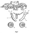
Figure 2 , thecylindrical heads 14 have chamferedends 17 that are used to assist in location of thecylindrical head 14 in to the socket. - Referring to
Figure 3 , thesocket 15 is a generally elongate aperture within the moulding of thecover plate 13. It is designed to retain thecylindrical head 14 while at the same time providing for rotation of thecylindrical head 14 within thesocket 15. - The
socket 15 comprises an opening in the cover plate withfirst surfaces 19 located on either side of thesocket 15. Thesurfaces 19 prevent the cylindrical head from passing through the opening of thesocket 15. Thesecond surfaces 20 are provided at either end of thesocket 15 and each comprise a recess with a U-shaped ledge that is diametrically opposed to thesurfaces 19. - Once the cylindrical head is located within the socket, the
surfaces cylindrical head 14 within thesocket 15. - The
outer wall 21 of thecover plate 13 is designed to be flexible. It is of a generally thin section and there is provided anelongate aperture 22 extending either side of thesocket 15 so that theouter wall 21 is not attached to theupper surface 23 of thecover plate 13. This enables theouter wall 21 to flex outwardly during insertion of thecylindrical head 14. - The pivoting joint is assembled by locating the first end of the
cylindrical head 14 into one of the recesses formed by asurface 20. In this position, the longitudinal axis of thecylindrical head 14 is in an angle with respect to the longitudinal axis of thesocket 15. The chamferedsurface 17 acts to lead the other end of thecylindrical head 14 into its respective recess formed bysurface 20. This is assisted by a small amount of flexing of theouter wall 21. Thecylindrical head 14 snaps into location within thesocket 15 so thatsurfaces cylindrical head 14. - Once in location, the resultant pivot joint is not easily disconnected. This is due to the support provided by
surfaces
Claims (9)
- A pivot connection for connecting a rack (11) to a cover plate (13) of a motor mechanism comprising: a substantially cylindrical head (14) at one end of the rack to be pivotally located, a socket (15) in the cover plate (13) into which said cylindrical head pivotally along the longitudinal axis locates, at least one first surface (19) on said socket that engages one side of the outer surface of said cylindrical head (14), characterized in that second surfaces (20) engage the chamfered ends (17) of said cylindrical head (14) on a side substantially opposite to said at least one first surface (19) to thereby retain said cylindrical head within said socket and said second surfaces (20) comprise U-shaped recesses.
- A pivot connection according to claim 1 wherein said first surface comprises a surface that restrains said cylindrical head (14) within said U-shaped recesses.
- A pivot connection according to either claim 1 or claim 2 wherein a portion of said socket is resiliently flexible to allow insertion of said cylindrical head due to said resiliently flexible portion deflecting sufficiently to allow insertion of said cylindrical head into said second surfaces.
- A pivot connection according to claim 3 wherein said cylindrical head has a chamfered surface to assist in initiating deflection of said resiliently flexible portion.
- A pivot connection according to any one of the preceding claims for use in a first plate that is pivotally connected to a second member, wherein said cylindrical head has attached a projection that is used to control movement of said first plate with respect to said second member.
- A pivot connection according to claim 5 wherein said projection is a gear toothed rack that engages with drive means in said second member.
- A pivot connection according to either claim 5 or 6 wherein said socket comprises an elongate slot in said first plate, said first surface comprises a pair of projections on either side of said slot projecting inwardly each having a curved surface that engages the other surface of said cylindrical head.
- A pivot connection according to claim 7 wherein said second surfaces are located at the end of said elongate slot.
- A pivot connection according to claim 8 wherein a second slot is formed in said first plate transverse to and at the end of said elongate slot to form said resiliently flexible portion.
Applications Claiming Priority (2)
| Application Number | Priority Date | Filing Date | Title |
|---|---|---|---|
| AU2004906227A AU2004906227A0 (en) | 2004-10-29 | A pivot connection | |
| PCT/AU2005/001674 WO2006045160A1 (en) | 2004-10-29 | 2005-10-31 | A pivot connection |
Publications (3)
| Publication Number | Publication Date |
|---|---|
| EP1805061A1 EP1805061A1 (en) | 2007-07-11 |
| EP1805061A4 EP1805061A4 (en) | 2009-08-12 |
| EP1805061B1 true EP1805061B1 (en) | 2010-06-16 |
Family
ID=36226756
Family Applications (1)
| Application Number | Title | Priority Date | Filing Date |
|---|---|---|---|
| EP05799174A Expired - Lifetime EP1805061B1 (en) | 2004-10-29 | 2005-10-31 | A pivot connection |
Country Status (5)
| Country | Link |
|---|---|
| US (1) | US8157468B2 (en) |
| EP (1) | EP1805061B1 (en) |
| AT (1) | ATE471253T1 (en) |
| DE (1) | DE602005021905D1 (en) |
| WO (1) | WO2006045160A1 (en) |
Cited By (1)
| Publication number | Priority date | Publication date | Assignee | Title |
|---|---|---|---|---|
| WO2017191132A1 (en) | 2016-05-04 | 2017-11-09 | SMR Patents S.à.r.l. | Positioning system for a rear view display device |
Families Citing this family (2)
| Publication number | Priority date | Publication date | Assignee | Title |
|---|---|---|---|---|
| CN103854984B (en) * | 2012-12-03 | 2017-03-01 | 中国科学院微电子研究所 | A method for manufacturing a dummy gate of the gate-last process and a dummy gate of the gate-last process |
| DE102019108303B4 (en) * | 2019-03-29 | 2020-12-10 | Mci (Mirror Controls International) Netherlands B.V. | Vision adjustment mechanism and adjusting means for such |
Family Cites Families (17)
| Publication number | Priority date | Publication date | Assignee | Title |
|---|---|---|---|---|
| US3564978A (en) * | 1968-12-03 | 1971-02-23 | Gen Motors Corp | Piston and connecting rod |
| DE2447688A1 (en) * | 1974-10-07 | 1976-04-08 | Maerklin & Cie Gmbh Geb | Remote controlled rear view mirror - uses universal joint as coupling between electric drive and mirror bearer |
| US4114988A (en) * | 1976-03-09 | 1978-09-19 | Ichikoh Industries, Limited | Mirror angle adjusting device, with consecutively driven worms in remotely controlled rear-view mirror apparatus |
| NL183086C (en) * | 1977-01-10 | 1988-07-18 | Koot Ind Bv | DEVICE FOR ADJUSTING AN OUTDOOR MIRROR AND A SECURITY HOUSING SUITABLE FOR RECEPTION OF THE DEVICE. |
| NL189807C (en) * | 1979-07-26 | 1993-08-02 | Iku Holding Montfoort Bv | MIRROR ADJUSTMENT FOR A VEHICLE OUTSIDE MIRROR. |
| US4477150A (en) * | 1979-10-17 | 1984-10-16 | Kabushiki Kaisha Tokai Rika Denki Seisakusho | Electric remote control rearview mirror |
| US4585200A (en) * | 1982-01-25 | 1986-04-29 | Magna International Inc. | Mounting for remotely controlled rear-view mirror |
| AU589033B2 (en) * | 1986-08-19 | 1989-09-28 | Mitsubishi Denki Kabushiki Kaisha | Constant-speed holding device for vehicles |
| US4915493A (en) * | 1989-01-04 | 1990-04-10 | Magna International Inc. | Automotive rear view mirror assembly |
| US5458365A (en) * | 1993-08-03 | 1995-10-17 | Morton International, Inc. | Adjustable snap away fastener |
| US5467230A (en) * | 1993-08-16 | 1995-11-14 | Lowell Engineering Corp. | Dual pivoted member mount for mirror |
| US5701211A (en) * | 1995-03-31 | 1997-12-23 | United Technologies Automotive Systems, Inc. | Vehicle mirror adjustment gear train |
| TW307179U (en) * | 1996-11-22 | 1997-06-01 | Xing-Yuan Xu | Multi-directional mop structure improvement |
| US5838507A (en) * | 1996-12-19 | 1998-11-17 | Lowell Engineering Corporation | Mirror assembly with friction drive |
| BR9702665A (en) * | 1997-07-28 | 1999-10-05 | Metagal Ind Stria E Comercio L | Multipurpose joint for external rear-view mirrors |
| US7231684B2 (en) * | 1998-06-25 | 2007-06-19 | Consumer Solutions, Inc. | Cleaning apparatus |
| US6942415B2 (en) * | 2002-02-26 | 2005-09-13 | The Torrington Company | Shaft assembly safety mechanism |
-
2005
- 2005-10-31 EP EP05799174A patent/EP1805061B1/en not_active Expired - Lifetime
- 2005-10-31 US US11/718,313 patent/US8157468B2/en active Active
- 2005-10-31 DE DE602005021905T patent/DE602005021905D1/en not_active Expired - Lifetime
- 2005-10-31 WO PCT/AU2005/001674 patent/WO2006045160A1/en not_active Ceased
- 2005-10-31 AT AT05799174T patent/ATE471253T1/en not_active IP Right Cessation
Cited By (2)
| Publication number | Priority date | Publication date | Assignee | Title |
|---|---|---|---|---|
| WO2017191132A1 (en) | 2016-05-04 | 2017-11-09 | SMR Patents S.à.r.l. | Positioning system for a rear view display device |
| DE102016108373A1 (en) | 2016-05-04 | 2017-11-09 | SMR Patents S.à.r.l. | Positioning system for a rearview display device |
Also Published As
| Publication number | Publication date |
|---|---|
| DE602005021905D1 (en) | 2010-07-29 |
| EP1805061A1 (en) | 2007-07-11 |
| EP1805061A4 (en) | 2009-08-12 |
| US8157468B2 (en) | 2012-04-17 |
| ATE471253T1 (en) | 2010-07-15 |
| US20090123223A1 (en) | 2009-05-14 |
| WO2006045160A1 (en) | 2006-05-04 |
Similar Documents
| Publication | Publication Date | Title |
|---|---|---|
| EP1908635B1 (en) | Vehicle outside mirror device | |
| KR100549975B1 (en) | Car outer mirror | |
| EP0511203B1 (en) | Automotive rearview mirror assembly | |
| JP4067912B2 (en) | Wiper blade coupling member and wiper blade | |
| EP1908633B1 (en) | Vehicle outside mirror device | |
| EP1739810A3 (en) | Electric motor | |
| CN107031573B (en) | Elements of a system for connecting a windscreen wiper blade holder to a drive arm | |
| JPH0256739U (en) | ||
| EP2484559B1 (en) | Mirror for vehicle | |
| US7739771B2 (en) | Windshield wiper drive assembly with dual sector gear drive | |
| US8157468B2 (en) | Pivot connection | |
| EP2212155B1 (en) | Mounting construction for an outside mirror unit | |
| KR102501553B1 (en) | Door edge protector device | |
| US5469753A (en) | Starter unit for a motor vehicle engine | |
| EP1584528B1 (en) | Wiper apparatus and wiper structure | |
| US20050029079A1 (en) | Turn signal switch device | |
| AU2005299261A1 (en) | A pivot connection | |
| JP4606880B2 (en) | Wiper drive | |
| WO2023007815A1 (en) | Input device | |
| JP2007314053A (en) | Wiper arm and wiper device | |
| JP2010048367A (en) | Ball joint structure and wiper arm | |
| JP4122081B2 (en) | Assembly structure of vehicle door handle device | |
| CN113747998A (en) | Positioning device | |
| JP2015174487A (en) | Driving device of vehicle side mirror | |
| KR100979708B1 (en) | Brush structure for actuator |
Legal Events
| Date | Code | Title | Description |
|---|---|---|---|
| PUAI | Public reference made under article 153(3) epc to a published international application that has entered the european phase |
Free format text: ORIGINAL CODE: 0009012 |
|
| 17P | Request for examination filed |
Effective date: 20070226 |
|
| AK | Designated contracting states |
Kind code of ref document: A1 Designated state(s): AT BE BG CH CY CZ DE DK EE ES FI FR GB GR HU IE IS IT LI LT LU LV MC NL PL PT RO SE SI SK TR |
|
| RIN1 | Information on inventor provided before grant (corrected) |
Inventor name: LYNN, TIM Inventor name: FLYNN, DANIEL Inventor name: DAVIES, GRAHAM |
|
| DAX | Request for extension of the european patent (deleted) | ||
| RAP1 | Party data changed (applicant data changed or rights of an application transferred) |
Owner name: VISIOCORP PATENTS S.A.R.L. |
|
| 111Z | Information provided on other rights and legal means of execution |
Free format text: AT BE BG CH CY CZ DE DK EE ES FI FR GB GR HU IE IS IT LT LU LV MC NL PL PT RO SE SI SK TR Effective date: 20080920 |
|
| A4 | Supplementary search report drawn up and despatched |
Effective date: 20090715 |
|
| RAP1 | Party data changed (applicant data changed or rights of an application transferred) |
Owner name: SMR PATENTS S.A.R.L. |
|
| 17Q | First examination report despatched |
Effective date: 20091021 |
|
| GRAP | Despatch of communication of intention to grant a patent |
Free format text: ORIGINAL CODE: EPIDOSNIGR1 |
|
| GRAS | Grant fee paid |
Free format text: ORIGINAL CODE: EPIDOSNIGR3 |
|
| GRAA | (expected) grant |
Free format text: ORIGINAL CODE: 0009210 |
|
| AK | Designated contracting states |
Kind code of ref document: B1 Designated state(s): AT BE BG CH CY CZ DE DK EE ES FI FR GB GR HU IE IS IT LI LT LU LV MC NL PL PT RO SE SI SK TR |
|
| REG | Reference to a national code |
Ref country code: CH Ref legal event code: EP |
|
| REG | Reference to a national code |
Ref country code: IE Ref legal event code: FG4D |
|
| REF | Corresponds to: |
Ref document number: 602005021905 Country of ref document: DE Date of ref document: 20100729 Kind code of ref document: P |
|
| REG | Reference to a national code |
Ref country code: NL Ref legal event code: VDEP Effective date: 20100616 |
|
| PG25 | Lapsed in a contracting state [announced via postgrant information from national office to epo] |
Ref country code: SE Free format text: LAPSE BECAUSE OF FAILURE TO SUBMIT A TRANSLATION OF THE DESCRIPTION OR TO PAY THE FEE WITHIN THE PRESCRIBED TIME-LIMIT Effective date: 20100616 Ref country code: LT Free format text: LAPSE BECAUSE OF FAILURE TO SUBMIT A TRANSLATION OF THE DESCRIPTION OR TO PAY THE FEE WITHIN THE PRESCRIBED TIME-LIMIT Effective date: 20100616 |
|
| LTIE | Lt: invalidation of european patent or patent extension |
Effective date: 20100616 |
|
| PG25 | Lapsed in a contracting state [announced via postgrant information from national office to epo] |
Ref country code: FI Free format text: LAPSE BECAUSE OF FAILURE TO SUBMIT A TRANSLATION OF THE DESCRIPTION OR TO PAY THE FEE WITHIN THE PRESCRIBED TIME-LIMIT Effective date: 20100616 Ref country code: LV Free format text: LAPSE BECAUSE OF FAILURE TO SUBMIT A TRANSLATION OF THE DESCRIPTION OR TO PAY THE FEE WITHIN THE PRESCRIBED TIME-LIMIT Effective date: 20100616 Ref country code: SI Free format text: LAPSE BECAUSE OF FAILURE TO SUBMIT A TRANSLATION OF THE DESCRIPTION OR TO PAY THE FEE WITHIN THE PRESCRIBED TIME-LIMIT Effective date: 20100616 Ref country code: AT Free format text: LAPSE BECAUSE OF FAILURE TO SUBMIT A TRANSLATION OF THE DESCRIPTION OR TO PAY THE FEE WITHIN THE PRESCRIBED TIME-LIMIT Effective date: 20100616 |
|
| PG25 | Lapsed in a contracting state [announced via postgrant information from national office to epo] |
Ref country code: GR Free format text: LAPSE BECAUSE OF FAILURE TO SUBMIT A TRANSLATION OF THE DESCRIPTION OR TO PAY THE FEE WITHIN THE PRESCRIBED TIME-LIMIT Effective date: 20100917 Ref country code: CY Free format text: LAPSE BECAUSE OF FAILURE TO SUBMIT A TRANSLATION OF THE DESCRIPTION OR TO PAY THE FEE WITHIN THE PRESCRIBED TIME-LIMIT Effective date: 20100616 Ref country code: PL Free format text: LAPSE BECAUSE OF FAILURE TO SUBMIT A TRANSLATION OF THE DESCRIPTION OR TO PAY THE FEE WITHIN THE PRESCRIBED TIME-LIMIT Effective date: 20100616 |
|
| PG25 | Lapsed in a contracting state [announced via postgrant information from national office to epo] |
Ref country code: EE Free format text: LAPSE BECAUSE OF FAILURE TO SUBMIT A TRANSLATION OF THE DESCRIPTION OR TO PAY THE FEE WITHIN THE PRESCRIBED TIME-LIMIT Effective date: 20100616 Ref country code: NL Free format text: LAPSE BECAUSE OF FAILURE TO SUBMIT A TRANSLATION OF THE DESCRIPTION OR TO PAY THE FEE WITHIN THE PRESCRIBED TIME-LIMIT Effective date: 20100616 |
|
| PG25 | Lapsed in a contracting state [announced via postgrant information from national office to epo] |
Ref country code: CZ Free format text: LAPSE BECAUSE OF FAILURE TO SUBMIT A TRANSLATION OF THE DESCRIPTION OR TO PAY THE FEE WITHIN THE PRESCRIBED TIME-LIMIT Effective date: 20100616 Ref country code: SK Free format text: LAPSE BECAUSE OF FAILURE TO SUBMIT A TRANSLATION OF THE DESCRIPTION OR TO PAY THE FEE WITHIN THE PRESCRIBED TIME-LIMIT Effective date: 20100616 Ref country code: RO Free format text: LAPSE BECAUSE OF FAILURE TO SUBMIT A TRANSLATION OF THE DESCRIPTION OR TO PAY THE FEE WITHIN THE PRESCRIBED TIME-LIMIT Effective date: 20100616 Ref country code: PT Free format text: LAPSE BECAUSE OF FAILURE TO SUBMIT A TRANSLATION OF THE DESCRIPTION OR TO PAY THE FEE WITHIN THE PRESCRIBED TIME-LIMIT Effective date: 20101018 Ref country code: IS Free format text: LAPSE BECAUSE OF FAILURE TO SUBMIT A TRANSLATION OF THE DESCRIPTION OR TO PAY THE FEE WITHIN THE PRESCRIBED TIME-LIMIT Effective date: 20101016 Ref country code: BE Free format text: LAPSE BECAUSE OF FAILURE TO SUBMIT A TRANSLATION OF THE DESCRIPTION OR TO PAY THE FEE WITHIN THE PRESCRIBED TIME-LIMIT Effective date: 20100616 |
|
| PG25 | Lapsed in a contracting state [announced via postgrant information from national office to epo] |
Ref country code: IT Free format text: LAPSE BECAUSE OF FAILURE TO SUBMIT A TRANSLATION OF THE DESCRIPTION OR TO PAY THE FEE WITHIN THE PRESCRIBED TIME-LIMIT Effective date: 20100616 |
|
| PLBE | No opposition filed within time limit |
Free format text: ORIGINAL CODE: 0009261 |
|
| STAA | Information on the status of an ep patent application or granted ep patent |
Free format text: STATUS: NO OPPOSITION FILED WITHIN TIME LIMIT |
|
| PG25 | Lapsed in a contracting state [announced via postgrant information from national office to epo] |
Ref country code: DK Free format text: LAPSE BECAUSE OF FAILURE TO SUBMIT A TRANSLATION OF THE DESCRIPTION OR TO PAY THE FEE WITHIN THE PRESCRIBED TIME-LIMIT Effective date: 20100616 |
|
| 26N | No opposition filed |
Effective date: 20110317 |
|
| PG25 | Lapsed in a contracting state [announced via postgrant information from national office to epo] |
Ref country code: MC Free format text: LAPSE BECAUSE OF NON-PAYMENT OF DUE FEES Effective date: 20101031 |
|
| REG | Reference to a national code |
Ref country code: CH Ref legal event code: PL |
|
| REG | Reference to a national code |
Ref country code: DE Ref legal event code: R097 Ref document number: 602005021905 Country of ref document: DE Effective date: 20110316 |
|
| PG25 | Lapsed in a contracting state [announced via postgrant information from national office to epo] |
Ref country code: CH Free format text: LAPSE BECAUSE OF NON-PAYMENT OF DUE FEES Effective date: 20101031 Ref country code: LI Free format text: LAPSE BECAUSE OF NON-PAYMENT OF DUE FEES Effective date: 20101031 |
|
| PG25 | Lapsed in a contracting state [announced via postgrant information from national office to epo] |
Ref country code: IE Free format text: LAPSE BECAUSE OF NON-PAYMENT OF DUE FEES Effective date: 20101031 |
|
| REG | Reference to a national code |
Ref country code: DE Ref legal event code: R082 Ref document number: 602005021905 Country of ref document: DE Representative=s name: JONES DAY RECHTSANWAELTE PATENTANWAELTE, DE |
|
| PG25 | Lapsed in a contracting state [announced via postgrant information from national office to epo] |
Ref country code: BG Free format text: LAPSE BECAUSE OF FAILURE TO SUBMIT A TRANSLATION OF THE DESCRIPTION OR TO PAY THE FEE WITHIN THE PRESCRIBED TIME-LIMIT Effective date: 20100616 Ref country code: HU Free format text: LAPSE BECAUSE OF FAILURE TO SUBMIT A TRANSLATION OF THE DESCRIPTION OR TO PAY THE FEE WITHIN THE PRESCRIBED TIME-LIMIT Effective date: 20101217 Ref country code: LU Free format text: LAPSE BECAUSE OF NON-PAYMENT OF DUE FEES Effective date: 20101031 |
|
| PG25 | Lapsed in a contracting state [announced via postgrant information from national office to epo] |
Ref country code: TR Free format text: LAPSE BECAUSE OF FAILURE TO SUBMIT A TRANSLATION OF THE DESCRIPTION OR TO PAY THE FEE WITHIN THE PRESCRIBED TIME-LIMIT Effective date: 20100616 |
|
| PG25 | Lapsed in a contracting state [announced via postgrant information from national office to epo] |
Ref country code: BG Free format text: LAPSE BECAUSE OF FAILURE TO SUBMIT A TRANSLATION OF THE DESCRIPTION OR TO PAY THE FEE WITHIN THE PRESCRIBED TIME-LIMIT Effective date: 20100916 |
|
| PG25 | Lapsed in a contracting state [announced via postgrant information from national office to epo] |
Ref country code: ES Free format text: LAPSE BECAUSE OF FAILURE TO SUBMIT A TRANSLATION OF THE DESCRIPTION OR TO PAY THE FEE WITHIN THE PRESCRIBED TIME-LIMIT Effective date: 20100927 |
|
| REG | Reference to a national code |
Ref country code: FR Ref legal event code: PLFP Year of fee payment: 11 |
|
| REG | Reference to a national code |
Ref country code: FR Ref legal event code: PLFP Year of fee payment: 12 |
|
| REG | Reference to a national code |
Ref country code: FR Ref legal event code: PLFP Year of fee payment: 13 |
|
| REG | Reference to a national code |
Ref country code: FR Ref legal event code: PLFP Year of fee payment: 14 |
|
| REG | Reference to a national code |
Ref country code: DE Ref legal event code: R084 Ref document number: 602005021905 Country of ref document: DE |
|
| P01 | Opt-out of the competence of the unified patent court (upc) registered |
Effective date: 20230616 |
|
| PGFP | Annual fee paid to national office [announced via postgrant information from national office to epo] |
Ref country code: DE Payment date: 20241022 Year of fee payment: 20 |
|
| PGFP | Annual fee paid to national office [announced via postgrant information from national office to epo] |
Ref country code: GB Payment date: 20241024 Year of fee payment: 20 |
|
| PGFP | Annual fee paid to national office [announced via postgrant information from national office to epo] |
Ref country code: FR Payment date: 20241024 Year of fee payment: 20 |
|
| REG | Reference to a national code |
Ref country code: DE Ref legal event code: R071 Ref document number: 602005021905 Country of ref document: DE |
|
| REG | Reference to a national code |
Ref country code: GB Ref legal event code: PE20 Expiry date: 20251030 |