EP1804409A1 - Method and device for reporting information related to interference components received by a first telecommunication device in some frequency subbands to a second telecommunication device - Google Patents
Method and device for reporting information related to interference components received by a first telecommunication device in some frequency subbands to a second telecommunication device Download PDFInfo
- Publication number
- EP1804409A1 EP1804409A1 EP05292815A EP05292815A EP1804409A1 EP 1804409 A1 EP1804409 A1 EP 1804409A1 EP 05292815 A EP05292815 A EP 05292815A EP 05292815 A EP05292815 A EP 05292815A EP 1804409 A1 EP1804409 A1 EP 1804409A1
- Authority
- EP
- European Patent Office
- Prior art keywords
- telecommunication device
- frequency
- telecommunication
- signals
- frequency subband
- Prior art date
- Legal status (The legal status is an assumption and is not a legal conclusion. Google has not performed a legal analysis and makes no representation as to the accuracy of the status listed.)
- Granted
Links
Images


Classifications
-
- H—ELECTRICITY
- H04—ELECTRIC COMMUNICATION TECHNIQUE
- H04W—WIRELESS COMMUNICATION NETWORKS
- H04W52/00—Power management, e.g. Transmission Power Control [TPC] or power classes
- H04W52/04—Transmission power control [TPC]
- H04W52/38—TPC being performed in particular situations
- H04W52/42—TPC being performed in particular situations in systems with time, space, frequency or polarisation diversity
-
- H—ELECTRICITY
- H04—ELECTRIC COMMUNICATION TECHNIQUE
- H04B—TRANSMISSION
- H04B17/00—Monitoring; Testing
- H04B17/20—Monitoring; Testing of receivers
- H04B17/24—Monitoring; Testing of receivers with feedback of measurements to the transmitter
-
- H—ELECTRICITY
- H04—ELECTRIC COMMUNICATION TECHNIQUE
- H04B—TRANSMISSION
- H04B17/00—Monitoring; Testing
- H04B17/30—Monitoring; Testing of propagation channels
- H04B17/309—Measuring or estimating channel quality parameters
- H04B17/345—Interference values
-
- H—ELECTRICITY
- H04—ELECTRIC COMMUNICATION TECHNIQUE
- H04L—TRANSMISSION OF DIGITAL INFORMATION, e.g. TELEGRAPHIC COMMUNICATION
- H04L27/00—Modulated-carrier systems
- H04L27/26—Systems using multi-frequency codes
- H04L27/2601—Multicarrier modulation systems
-
- H—ELECTRICITY
- H04—ELECTRIC COMMUNICATION TECHNIQUE
- H04W—WIRELESS COMMUNICATION NETWORKS
- H04W52/00—Power management, e.g. Transmission Power Control [TPC] or power classes
- H04W52/04—Transmission power control [TPC]
-
- H—ELECTRICITY
- H04—ELECTRIC COMMUNICATION TECHNIQUE
- H04L—TRANSMISSION OF DIGITAL INFORMATION, e.g. TELEGRAPHIC COMMUNICATION
- H04L1/00—Arrangements for detecting or preventing errors in the information received
- H04L1/0001—Systems modifying transmission characteristics according to link quality, e.g. power backoff
- H04L1/0002—Systems modifying transmission characteristics according to link quality, e.g. power backoff by adapting the transmission rate
- H04L1/0003—Systems modifying transmission characteristics according to link quality, e.g. power backoff by adapting the transmission rate by switching between different modulation schemes
-
- H—ELECTRICITY
- H04—ELECTRIC COMMUNICATION TECHNIQUE
- H04L—TRANSMISSION OF DIGITAL INFORMATION, e.g. TELEGRAPHIC COMMUNICATION
- H04L1/00—Arrangements for detecting or preventing errors in the information received
- H04L1/0001—Systems modifying transmission characteristics according to link quality, e.g. power backoff
- H04L1/0009—Systems modifying transmission characteristics according to link quality, e.g. power backoff by adapting the channel coding
Definitions
- the present invention relates generally to telecommunication systems and in particular, to methods and devices for reporting information related to interference components received by a telecommunication device to another telecommunication device.
- the base station is expected to control the transmission of signals to terminals.
- the base station determines the modulation and coding schemes to be used for transferring signals representative of groups of data to the terminals and/or determines the terminals to which, signals have to be transferred on a subset of frequency subbands, according the quality of the communication channel between the base station and the terminals.
- the base station obtains from the terminals, information related to the quality of the channel between the base station and the terminals.
- the Signal to Interference plus Noise Ratio measured by the terminals is used as a channel quality indication.
- Each terminal reports to the base station channel quality indication for each of the subbands of the OFDMA system.
- Such channel quality indications reporting is performed by transferring a large amount of information bits from each terminal to the base station. Such reporting requires an important part of the available bandwidth of the OFDMA system.
- each terminal transfers pilot signals to the base station, the base station receives the pilot signals, determines, for each of the terminals, the channel responses from the received pilot signals, forms a channel matrix which is representative of the channel conditions and uses the determined matrix in order to send the signals which have to be transferred to the respective terminals.
- the coefficients of the channel matrix are the complex propagation gain between the antennas of the base station and the antennas of the terminal which sent the pilot signals.
- Such determination of the channel conditions is effective when the terminal receives, in parallel with the signals transferred by the base station, interference components of the same power in each subband. If the terminal receives interference components of different power in some subbands, it is also necessary for the terminals to report their respective interference components or their respective Signal to Interference plus Noise Ratio in each subband. Such reporting requires also an important part of the available bandwidth of the OFDMA system.
- the aim of the invention is therefore to propose methods and devices which allow the reporting of information related to interference components received by a telecommunication device to another telecommunication device without decreasing in an important manner the bandwidth of the uplink channel which is used for classical data transmission.
- the present invention concerns a method for reporting, through a wireless network using multiple frequency subbands, interference components received by a first telecommunication in a first and a second frequency subbands of the wireless network, to a second telecommunication device, characterised in that the method comprises the steps executed by the first telecommunication device of :
- the present invention concerns also a device for reporting, through a wireless network using multiple frequency subbands, interference components received by a first telecommunication in a first and a second frequency subbands of the wireless network, to a second telecommunication device, characterised in that the device for reporting interference components is included in first telecommunication device and comprises :
- the first telecommunication device can report information related to interference components it receives in some frequency subbands to a second telecommunication device without decreasing in an important manner the bandwidth which is used for classical data transmission.
- the first telecommunication device and the second telecommunication device comprise one antenna, and the first and second determined weights are respectively inversely proportional to the interference components measured in the first and second frequency subbands.
- the determination, for each first and second frequency subbands, of at least one first and second weights from the measured interference components in the respective first and second frequency subbands is simple and accurate.
- the first telecommunication device determines a power information for the first and second frequency subbands, and transfers to the second telecommunication device signals representing the power information.
- the second telecommunication device is aware about that adjustment.
- the second telecommunication device is aware about each adjustment.
- the first telecommunication devices comprises M antennas
- the second telecommunication device comprises N antennas
- the measured interferences components are set, for at least the first and second frequency subbands, under the form of an interference correlation matrix R IN,l , where l denotes the indicia of the first and second frequency subbands, and the determination, for each first and second frequency subbands, of the at least one first and second weights from the measured interference components is decomposed into :
- the first telecommunication device can report information related to interference components it receives in some frequency subbands to a second telecommunication device without decreasing the bandwidth which is used for classical data transmission.
- the present invention is also adapted for systems which combine multi frequency subbands and MIMO schemes.
- the determination of the weighting vectors g l,1 to g l,M is simple fits with the spatial direction of the received interference components and their intensity.
- the first telecommunication device determines at least a power coefficient, weights the at most M pilot signals by the power coefficient and transfers to the second telecommunication device signals representing at least a power information which is related to the determined power coefficient.
- the second telecommunication device is aware about that adjustment.
- each frequency subband include plural subcarrier frequencies and the measured the interference components received by the first telecommunication device in the first frequency subband are the average of the interference components measured in each of the subcarrier frequencies of the first frequency subband and the measured the interference components received by the first telecommunication device in the second frequency subband are the average of the interference components measured in each of the subcarrier frequencies of the second frequency subband.
- the interference components measured in each subband frequency takes into account all the interference components received in each subcarrier frequency of a frequency subband.
- each frequency subband include plural subcarrier frequencies and the measured the interference components received by the first telecommunication device in the first frequency subband are the interference components measured in at least a subcarrier frequency of the first frequency subband and the measured the interference components received by the first telecommunication device in the second frequency subband the interference components measured in at least a subcarrier frequency of the first frequency subband.
- the present invention concerns a method for controlling the transfer of signals to a first telecommunication device by a second telecommunication device through a wireless network using multiple frequency subbands, characterised in the method comprises the steps executed by the second telecommunication device of :
- the present invention concerns also a device for controlling the transfer of signals to a first telecommunication device by a second telecommunication device through a wireless network using multiple subbands, characterised in the device for controlling the transfer of signals is included in the second telecommunication device and comprises :
- the second telecommunication device is informed about the interference components received by the first telecommunication device in some frequency subbands without decreasing in an important manner the bandwidth which is used for classical data transmission and can then reduce the effect of the interference components on the transferred signals representative of a group of information.
- the first telecommunication device and the second telecommunication device comprise one antenna, and the second telecommunication device receives, from the first telecommunication device, signals representing at least a power information and the information representative of interference components received by the first telecommunication device is determined from the at least first and second pilot signals and the at least one power information.
- the second telecommunication device is aware about that adjustment.
- control of the transfer of signals representative of a group of data to the first telecommunication device is the determination of the transmission power to be used for transferring at least a group of data to the first telecommunication device.
- the second telecommunication device can reduce the effect of the interference components received by the first telecommunication device.
- control of the transfer of signals representative of a group of data to the first telecommunication device is the determination of the modulation and coding scheme to be used for transferring signals representative of the group of data to the first telecommunication device.
- the resources of the wireless telecommunication network system are used efficiently.
- plural first telecommunication devices transfer at least a first and second pilot signals and signals representative of at least a power information and in that the control of the transfer of signals representative of the group of data to the first telecommunication device is the determination to which first telecommunication device or devices among the plural first telecommunication devices, signals representing at least a group of data have to be transferred.
- the resources of the wireless telecommunication network system are used efficiently.
- the present invention is also adapted for systems which combine multi frequency subbands and MIMO schemes.
- the second telecommunication device comprises N antennas and the determined information representative of interference components received by a first telecommunication device in each first and second frequency subbands are a first and a second weighting vectors and in that the control of the transfer of signals representative of a group of data to the first telecommunication device in the first and second frequency subbands is made by weighting the signals representative of the group of data respectively by the first and the second weighting vectors.
- the second telecommunication device can direct the signals transfer to the first telecommunication device according to the interference components received by the first telecommunication device.
- the first telecommunication device comprises M antennas, at most M pilot signals are received in each first and second frequency subbands and each weighting vector is determined by :
- the present invention is also adapted for systems which combine multi frequency subbands and MIMO schemes.
- the product of two matrices obtained from the calculated matrix is equal to J l * ⁇ J l T , where J l * denotes the conjugate of J l and J l T denotes the transpose of J l .
- the second telecommunication device receives from the first telecommunication device, signals representing at least a power information and the information representative of interference components received by the first telecommunication device is determined from the at most M received pilot signals and the at least one power information.
- the second telecommunication device is aware about that adjustment.
- control of the transfer of signals representative of a group of data to the first telecommunication device is the determination of the modulation and coding scheme to be used for transferring signals representative of a group of data to the first telecommunication device.
- plural first telecommunication devices transfer pilot signals and signals representative of a power information and the control of the transfer of signals representative of a group of data to the first telecommunication device is the determination to which first telecommunication device or devices among the plural first telecommunication devices signals representing at least a group of data have to be transferred.
- the resources of the wireless telecommunication network system are used efficiently.
- the present invention concerns computer programs which can be directly loadable into a programmable device, comprising instructions or portions of code for implementing the steps of the methods according to the invention, when said computer programs are executed on a programmable device.
- the present invention concerns the signals transferred according to the present invention.
- Fig. 1 is a diagram representing the architecture of a first telecommunication system in which the present invention is implemented.
- At least one first telecommunication device 20 l or 20 K is linked through a wireless network 15 to a second telecommunication device 10 using an uplink and a downlink channel.
- the second telecommunication device 10 is a base station or a node of the wireless network 15.
- the first telecommunication devices 20 l to 20 K are terminals like mobile phones or personal computers.
- the telecommunication network 15 is a wireless telecommunication system which uses Time Division Duplexing scheme (TDD).
- TDD Time Division Duplexing scheme
- the signals transferred in uplink and downlink channels are duplexed in different time periods of the same frequency band.
- the signals transferred within the wireless network 15 share the same frequency spectrum.
- the channel responses between the uplink and downlink channels of the telecommunication network 15 are reciprocal.
- Reciprocal means that if the downlink channel conditions are represented by a downlink matrix the uplink channel conditions can be expressed by an uplink matrix which is the transpose of the downlink matrix.
- the first telecommunication network 15 is according to the present invention, a wireless telecommunication system which uses Orthogonal Frequency Division Multiplexing Access scheme (OFDMA).
- OFDMA Orthogonal Frequency Division Multiplexing Access scheme
- each frequency subband is associated with respective subcarriers upon which data may be modulated.
- the second telecommunication device 10 transfers signals representatives of a group of data to the first telecommunication devices 20 1 to 20 K through the downlink channel and the first telecommunication devices 20 1 to 20 K transfer signals to the second telecommunication device 10 through the uplink channel.
- the second telecommunication device 10 has one antenna BSAn.
- the second telecommunication device 10 determines the modulation and coding scheme to be used for transferring groups of data to each first telecommunication devices 20 and/or determines the first telecommunication device 20 to which, signals representative of a group of data have to be sent according to signals transferred by the first telecommunication devices 20 as it will be disclosed hereinafter.
- the signals transferred by the first telecommunication devices 20 l to 20 K are signals representatives of a group of data and/or pilot signals which are weighted by at least a weight determined from the interference components measured by the first telecommunication devices 20 l to 20 K .
- Each first telecommunication device 20 l to 20 K has one antenna noted respectively MSAnl to MSAnK.
- a group of data is as example a frame constituted at least by a header field and a payload field which comprises classical data like data related to a phone call, or a video transfer and so on.
- Pilot signals are predetermined sequences of symbols known by the telecommunication devices. Pilot signals are as example and in a non limitative way Walsh Hadamard sequences.
- Fig. 2 is a diagram representing the architecture of a first telecommunication device according to a first mode of realisation of the present invention which is used in the first telecommunication system.
- the first telecommunication device 20 as example the first telecommunication device 20 k with k comprised between l and K , has, for example, an architecture based on components connected together by a bus 201 and a processor 200 controlled by programs related to the algorithm as disclosed in the Fig. 4.
- the first telecommunication device 20 is, in a variant, implemented under the form of one or several dedicated integrated circuits which execute the same operations as the one executed by the processor 200 as disclosed hereinafter.
- the bus 201 links the processor 200 to a read only memory ROM 202, a random access memory RAM 203 and a channel interface 205.
- the read only memory ROM 202 contains instructions of the programs related to the algorithm as disclosed in the Fig. 4 which are transferred, when the first telecommunication device 20 k is powered on to the random access memory RAM 203.
- the RAM memory 203 contains registers intended to receive variables, and the instructions of the programs related to the algorithm as disclosed in the Fig. 4.
- Each weighting coefficient ⁇ I l is determined by a power information ⁇ which is representative of the transmit power and the power I l of the interference components measured by the first telecommunication device 20 k in the l -th frequency subband.
- the interference components are electromagnetic waveforms generated by other first telecommunication devices, electromagnetic waveforms radiated by any electric equipment and/or any other noise received by the first telecommunication device 20 k .
- Each weighting coefficient ⁇ I l is used for weighting respectively a pilot signal to be transferred to the second telecommunication device 10 through each of the at most L frequency subbands.
- the channel interface 205 comprises an interference measurement module 210.
- h l is the complex propagation gain in the frequency subband l between the second telecommunication device 10 and the first telecommunication device 20 k
- the interferences components may vary in the different subcarrier frequencies included in a frequency subband.
- the interferences components in the subcarrier frequencies of a subband are then averaged.
- the measured interference components in each frequency subband are the interference components measured in at least a subcarrier of a frequency subband, as example the largest interference components measured in a frequency carrier of a frequency subband.
- the channel interface 205 comprises at most L multiplication modules.
- the channel interface 205 comprises L multiplication modules noted Mul l to Mul L which weight respectively the pilot signals R l (p) to R L (p) by the respective weighting coefficients / I l ⁇ .
- the channel interface 205 comprises an Inverse Fast Fourier Transform module (IFFT) 220 which makes an inverse fast Fourier transform on each of the weighted pilot signals R l (p) to at most R L (P).
- IFFT Inverse Fast Fourier Transform module
- the channel interface 205 comprises a parallel to serial converter 230 which converted the at most L inversed Fourier transformed weighted pilot signals into signals transferred by the antenna MSAn.
- the channel interface 205 further comprises means for transferring a power information ⁇ to the second telecommunication device 10.
- the power information ⁇ represents the multiplying factor used by the first telecommunication device 20 k for weighting the pilot signals.
- each determined power information is transferred to the second telecommunication device 10.
- Fig. 3 is a diagram representing the architecture of the second telecommunication device according to the first mode of realisation of the present invention which is used in the first telecommunication system.
- the second telecommunication device 10 has, for example, an architecture based on components connected together by a bus 301 and a processor 300 controlled by programs as disclosed in the Fig. 5.
- the second telecommunication device 10 is, in a variant, implemented into one or several dedicated integrated circuits which execute the same operations as the one executed by the processor 300 as disclosed hereinafter.
- the bus 301 links the processor 300 to a read only memory ROM 302, a random access memory RAM 303 and a channel interface 305.
- the read only memory ROM 302 contains instructions of the programs related to the algorithm as disclosed in the Fig. 5 which are transferred, when the second telecommunication 10 is powered on to the random access memory RAM 303.
- the RAM memory 303 contains registers intended to receive variables, and the instructions of the programs related to the algorithm as disclosed in the Fig. 5.
- the processor 300 is able to determine from at least signals transferred by a first telecommunication device 20 k which are representative of pilot signals weighted by weighting coefficients / I l ⁇ transferred in the frequency subbands of the OFDMA system, the modulation and coding scheme to be used for the transfer of groups of signals to that first telecommunication device 20 k and/or to determine the first telecommunication device 20 k to which signals representative of a group of data have to be sent according to signals transferred by the first telecommunication devices 20.
- the channel interface 305 comprises means for receiving at least one power information ⁇ from each second telecommunication device 20.
- Fig. 4 is an algorithm executed by the first telecommunication device according to the first mode of realisation of the present invention.
- the present algorithm is more precisely executed by each of the first telecommunication devices 20 1 to 20 K .
- the processor 200 determines the power information ⁇ which is representative of the transmit power.
- the processor 200 transfers the power information ⁇ to the channel interface 305 which transfers at least a signal representative of the power information ⁇ to the second telecommunication 10.
- the processor 200 determines the power information ⁇ according to the following formula:
- the SINR reporting is achieved by transmitting the pilot signal with a power which is inverse proportional to the interference power I l .
- Fig. 5 is an algorithm executed by the second telecommunication device according to the first mode of realisation of the present invention.
- step S500 the signals transferred at step S402 by the first telecommunication devices 20 l to 20 K , are received through the channel interface 305 of the second telecommunication device 10.
- the p -th symbol transferred by a first telecommunication device 20 k in the l -th subband by the second telecommunication device 10 is expressed as :
- the processor 300 estimates the SINR of the first telecommunication devices 20 in each frequency subbands.
- the number of frequency subbands can either equal to two to L .
- the processor 300 determines the modulation and coding scheme to be used for the transfer of signals representative of groups of date to each first telecommunication device 20 k in the respective subbands using the determined SINR in each subbands.
- the processor 300 uses the determined SINR in each subbands, determines the transmission power P BS,l in each subband in order to adjust the SINR ⁇ l pre to a predetermined value.
- the processor 300 determines, using the determined SINR for all the first telecommunication devices 20 1 to 20 K , the first telecommunication device 20 to which signals representative of a group of data have to be sent.
- Fig. 6 is a diagram representing the architecture of a second telecommunication system in which the present invention is implemented.
- At least one first telecommunication device 68 k is linked through a wireless network 65 to a second telecommunication device 60 using an uplink and a downlink channel.
- the second telecommunication device 60 is a base station or a node of the wireless network 65.
- the first telecommunication devices 68 l to 68 K are terminals like mobile phones or personal computers.
- the second telecommunication system is a wireless telecommunication system which uses OFDMA in combination with TDD and MIMO schemes.
- the signals transferred in uplink and downlink channels are duplexed in different time periods of same frequency bands.
- the overall system bandwidth is partitioned into L plural orthogonal frequency subbands, which are also referred to as frequency bins or subchannels.
- each frequency subband is associated with subcarriers upon which data may be modulated.
- the channel responses between the uplink and downlink channels of the telecommunication network 65 are reciprocal.
- Reciprocal means that if the downlink channel conditions are represented by a downlink matrix the uplink channel conditions can be expressed by an uplink matrix which is the transpose of the downlink matrix.
- the second telecommunication device 60 transfers signals representatives of a group of data to the first telecommunication devices 68 l to 68 K through the downlink channel and the first telecommunication devices 68 l to 68 K transfer signals to the second telecommunication device 60 through the uplink channel.
- the signals transferred by the first telecommunication devices 68 l to 68 K are signals representatives of a group of data and/or pilot signals which are weighted by at least a weight determined from the interference components measured by the first telecommunication devices 68 l to 68 K .
- a group of data is as example a frame constituted at least by a header field and a payload field which comprises classical data like data related to a phone call, or a video transfer and so on.
- Pilot signals are predetermined sequences of symbols known by the telecommunication devices. Pilot signals are as example and in a non limitative way Walsh Hadamard sequences.
- the second telecommunication device 60 has at least one antenna and more preferably N antennas noted BSAntl to BSAntN.
- the second telecommunication device 60 preferably controls the spatial direction of the signals transferred to each of the first telecommunication devices 68 according to at least signals transferred by the first telecommunication devices 68 l to 68 K as it will be disclosed hereinafter.
- the second telecommunication device 60 transmits signals representatives of a group of data to a given first telecommunication device 68 k through the downlink channel
- the second telecommunication device 60 performs beamforming, i.e. controls the spatial direction of the transmitted signals.
- the ellipse noted BF1 in the Fig. 6 shows the pattern of the radiated signals by the antennas BSAntl to BSAntN which are transferred to the first telecommunication device 68 1 by the second telecommunication device 60.
- the ellipse noted BFK in the Fig. 6 shows the pattern of the radiated signals by the antennas BSAnt1 to BSAntN which are transferred to the first telecommunication device 68 K by the second telecommunication device 60.
- the ellipse noted BF 1 in the Fig. 6 shows the pattern of the radiated signals by the antennas MS1Ant1 to MS1AntM which are transferred by the first telecommunication device 68 l to the second telecommunication device 60.
- the ellipse noted BFK in the Fig. 6 shows the pattern of the radiated signals by the antennas MSKAnt1 to MSKAntM which are transferred by the first telecommunication device 68 K to the second telecommunication device 60.
- Fig. 7 is a diagram representing the architecture of the first telecommunication device according to the second mode of realisation of the present invention which is used in the second telecommunication system.
- the first telecommunication device 68 as example the first telecommunication device 68 k with k comprised between 1 to K , has, for example, an architecture based on components connected together by a bus 701 and a processor 700 controlled by programs related to the algorithm as disclosed in the Fig. 11.
- the first telecommunication device 68 is, in a variant, implemented under the form of one or several dedicated integrated circuits which execute the same operations as the one executed by the processor 700 as disclosed hereinafter.
- the bus 701 links the processor 700 to a read only memory ROM 702, a random access memory RAM 703 and a channel interface 705.
- the read only memory ROM 702 contains instructions of the programs related to the algorithm as disclosed in the Fig. 11 which are transferred, when the first telecommunication device 68 k is powered on to the random access memory RAM 703.
- the RAM memory 703 contains registers intended to receive variables, and the instructions of the programs related to the algorithm as disclosed in the Fig. 11.
- the channel interface 705 will be described in more detail in reference to the Fig. 8.
- Fig. 8 is a diagram representing the architecture of a channel interface of the first telecommunication device according to the second mode of realisation of the present invention.
- the channel interface 705 comprises an interference measurement module 800 which measures the interference components measured by the first telecommunication device 68 k .
- the second telecommunication device 60 transfers, in each of the L frequency subbands, a signal s l (p) with a power P BS, l and ( E ⁇
- the channel interface 705 comprises L pilot signals processing devices noted 801 l to 810 L , M Inverse Fast Fourier Transform module (IFFT) noted 801 l to 801 M which make an inverse fast Fourier transform and M parallel to serial converters noted 802 1 to 802 M which converted the M inversed Fourier transformed signals into signals transferred to the respective antennas MSkAnt1 to MSkAntM.
- IFFT Inverse Fast Fourier Transform module
- the channel interface 705 further comprises means for transferring at least a power information ⁇ l to the second telecommunication device 60.
- These means are noted Mulc IlU to Mulc MlU in the Fig. 8.
- Each pilot signals processing device 801 l comprises M duplication modules noted Cp I1U to CP MIU which duplicate the weighted pilot symbols and means for weighting the duplicated pilot signals to be transferred to the second telecommunication device 60 by weighting vectors g m,l .
- the means for weighting the weighted pilot signals to be transferred to the second telecommunication device 60 are composed of, M*M uplink multiplication modules noted Mul lllU to Mul MlMU , M uplink summation modules noted Sum llU to Sum MlU .
- each uplink weighting vector g m,l The signals weighted by the first element of each uplink weighting vector g m,l are then summed by the adder Sum llU and transferred to the IFFT module 801 2 .
- the signals weighted by the second element of each uplink weighting vector g m,l are then summed and transferred to the IFFT module 801 2 and so on until the M -th element of the weighting vectors g m,l .
- the signals are, prior to be transferred to each antenna MSkAnt1 to MSkAntM, frequency up converted, mapped and so on, as it is done in classical wireless telecommunication devices.
- M-M' pilot signals are set to null value and/or their corresponding weighting vectors g m,l are also set to null value.
- pilot signals transferred in each frequency subband a identical, but we can understand that the pilot symbols used in a frequency subband can be different from the used in another or the other frequency subbands.
- Fig. 9 is a diagram representing the architecture of the second telecommunication device according to the second mode of realisation of the present invention which is used in the second telecommunication system.
- the second telecommunication device 60 has, for example, an architecture based on components connected together by a bus 901 and a processor 900 controlled by programs related to the algorithm as disclosed in the Fig. 12.
- the second telecommunication device 60 is, in a variant, implemented under the form of one or several dedicated integrated circuits which execute the same operations as the one executed by the processor 900 as disclosed hereinafter.
- the bus 901 links the processor 900 to a read only memory ROM 902, a random access memory RAM 903 and a channel interface 905.
- the read only memory ROM 902 contains instructions of the programs related to the algorithm as disclosed in the Fig. 12 which are transferred, when the second telecommunication device 60 is powered on to the random access memory RAM 903.
- the RAM memory 903 contains registers intended to receive variables, and the instructions of the programs related to the algorithm as disclosed in the Fig. 12.
- the processor 900 is also able to determine, from at least signals transferred by each first telecommunication device 68 1 to 68 K which are representative of pilot signals weighted by the power coefficients ⁇ l and uplink weighting vectors representative of the interference components received by the first telecommunication device 68 k which has transferred the signals, the downlink weighting vectors w n,l to be used by the second telecommunication device 60 when it transfers signals to the first telecommunication device 68 k which has transferred the signals.
- the channel interface 905 comprises means for receiving a power information ⁇ or plural power information ⁇ l from each the second telecommunication device 68.
- the channel interface 905 comprises means for receiving weighted pilot signals from each first telecommunication device 68 l to 68 K , means for receiving, from each first telecommunication device 68 l to 68 K , a power information ⁇ l for each frequency subband or a single power information ⁇ for all of the frequency subbands.
- the channel interface 905 comprises means for directing, using the downlink weighting vectors w n,l , the signals representatives of groups of data transferred by the second telecommunication device 60 to a first telecommunication device 68 l to 68 K .
- the channel interface 905 will be disclosed in more details in reference to the Fig. 10.
- Fig. 10 is a diagram representing the architecture of a channel interface of the second telecommunication device according to the second mode of realisation of the present invention.
- the channel interface 905 of the second telecommunication device 10 comprises a pilot signal reception module 1000.
- the pilot signal reception module 1000 comprises means for receiving pilot signals weighted according the present invention by the first telecommunication devices 68 l to 68 K and a power information ⁇ l for each frequency subband or a single power information ⁇ for all of the frequency subbands from each of the first telecommunication devices 68 l to 68 K .
- the channel interface 905 comprises L signals processing devices noted 1010 1 to 1010 L , N IFFT modules noted 10011 to 1001 N and N parallel to serial converters noted 1002 l to 1002 N which converted the N inversed Fourier transformed signals into signals transferred to the respective antennas BSAnt1 to BSAntN.
- the means for weighting the weighted signals to be transferred to the first telecommunication devices 68 are composed of, N*N downlink multiplication modules noted Mul lllD to Mul NlND , N downlink summation modules noted Sum llD to Sum NlD .
- each uplink weighting vector w n,l The signals weighted by the first element of each uplink weighting vector w n,l are then summed by the adder Sum llD and transferred to the IFFT module 1001 1 .
- the signals weighted by the second element of each uplink weighting vector w n,l are then summed and transferred to the IFFT module 1001 2 and so on until the N -th element of the weighting vectors w n,l .
- the signals are, prior to be transferred to each antenna BSAnt1 to BSAntN, frequency up converted, mapped and so on, as it is done in classical wireless telecommunication devices.
- N groups of data can be transferred to the first telecommunication devices 68 as it will be disclosed hereinafter.
- the signals representative of N-N' groups of data are set to null value and/or their corresponding weighting vectors w n,l are also set to null value.
- Fig. 11 is an algorithm executed by the first telecommunication device according to the second mode of realisation of the present invention.
- the present algorithm is more precisely executed by each of the first telecommunication devices 68 l to 68 K .
- the power information ⁇ l can be set to any value or to a predetermined value known by all the telecommunication devices 60 or 68.
- the processor 700 determines the same power information ⁇ for all of the frequency subbands or determines a power information ⁇ l for each subband.
- ⁇ l P S ⁇ 1 M ⁇ tr R IN , l - 1 - 1
- the processor 700 doesn't transfer the corresponding uplink weighting vector to the channel interface. In such case, a reduced number of pilot signals needs then to be transferred to the second telecommunication device 60.
- the processor 700 transfers at most M pilot signals to the channel interface 705.
- each of the at most M pilot signals are duplicating at most M times.
- Fig. 12 is an algorithm executed by the second telecommunication device according to the second mode of realisation of the present invention.
- the signals transferred at step S116 by at least a first telecommunication device 68 k are received through the channel interface 905 of the second telecommunication device 60.
- the p-th sample x BS,l (p) of the receive signal by the second telecommunication device 60 is expressed as:
- the processor 900 estimates, for each of the L frequency subbands, the product of matrices H l H ⁇ G l .
- the processor 900 executes, for each of the L frequency subbands, an eigenvalue decomposition of J l * ⁇ J l T .
- the processor 900 determines, for each of the L frequency subbands, the largest eigenvalue noted ⁇ ⁇ J l * ⁇ J l T ⁇ of each of the matrices J l * ⁇ J l T .
- the processor 900 determines the at least two largest eigenvalues of the matrix J l * ⁇ J l T .
- the downlink weighting vector W n,l for the l -th frequency subband is the eigenvector noted e ⁇ J l * ⁇ J l T ⁇ which corresponds to largest the eigenvalue.
- the processor 900 determines at least two downlink weighting vectors for each subband.
- the processor 900 determines the downlink weighting vector w n,l for the l -th frequency subband, with n being equal or upper than 2, are the eigenvector noted which corresponds to largest the at least two eigenvalues.
- the processor 900 estimates, for each of the L frequency subbands, the SINR of the first telecommunication device 68 k which has transferred the signals received at step S120.
- the second telecommunication device 60 can direct the signals transferred to the first telecommunication device 68 k which has transferred the signals received at step S120 considering the effect of interferences on the first telecommunication device 68 k without having the complete knowledge of H l and R IN,l .
- the processor 900 determines the modulation and coding scheme to be used for the transfer of signals representative of a group of data to the first telecommunication device 68 k using the determined SINR or the processor 300 determines, using the predicted SINR of all the first telecommunication devices 68 1 to 68 K , the first telecommunication device 68 k to which signals representative of a group of data have to be sent.
- the processor 900 adjusts the transmission power P S n ⁇ l by setting the predicted SINR to a predetermined SINR.
Landscapes
- Engineering & Computer Science (AREA)
- Computer Networks & Wireless Communication (AREA)
- Signal Processing (AREA)
- Physics & Mathematics (AREA)
- Electromagnetism (AREA)
- Quality & Reliability (AREA)
- Mobile Radio Communication Systems (AREA)
- Radio Transmission System (AREA)
Abstract
Description
- The present invention relates generally to telecommunication systems and in particular, to methods and devices for reporting information related to interference components received by a telecommunication device to another telecommunication device.
- Recently, efficient transmission schemes in space and frequency domains have been investigated to meet the growing demand for high data rate wireless communications. In recent years, Orthogonal Frequency Division Multiplexing Access scheme have been discussed for mobile communication systems.
- In such systems, the base station is expected to control the transmission of signals to terminals. The base station determines the modulation and coding schemes to be used for transferring signals representative of groups of data to the terminals and/or determines the terminals to which, signals have to be transferred on a subset of frequency subbands, according the quality of the communication channel between the base station and the terminals.
- For that, the base station obtains from the terminals, information related to the quality of the channel between the base station and the terminals.
- Classically, the Signal to Interference plus Noise Ratio measured by the terminals is used as a channel quality indication. Each terminal reports to the base station channel quality indication for each of the subbands of the OFDMA system. Such channel quality indications reporting is performed by transferring a large amount of information bits from each terminal to the base station. Such reporting requires an important part of the available bandwidth of the OFDMA system.
- When the base station and/or the terminals have multiple antennas, the amount of information to be transferred as channel quality indications increases according to the number of antennas. When the channel is reciprocal, e.g. in Time Division Multiplex systems, the channel conditions are obtained according to the following method : each terminal transfers pilot signals to the base station, the base station receives the pilot signals, determines, for each of the terminals, the channel responses from the received pilot signals, forms a channel matrix which is representative of the channel conditions and uses the determined matrix in order to send the signals which have to be transferred to the respective terminals.
- The coefficients of the channel matrix are the complex propagation gain between the antennas of the base station and the antennas of the terminal which sent the pilot signals.
- Such determination of the channel conditions is effective when the terminal receives, in parallel with the signals transferred by the base station, interference components of the same power in each subband. If the terminal receives interference components of different power in some subbands, it is also necessary for the terminals to report their respective interference components or their respective Signal to Interference plus Noise Ratio in each subband. Such reporting requires also an important part of the available bandwidth of the OFDMA system.
- The aim of the invention is therefore to propose methods and devices which allow the reporting of information related to interference components received by a telecommunication device to another telecommunication device without decreasing in an important manner the bandwidth of the uplink channel which is used for classical data transmission.
- To that end, the present invention concerns a method for reporting, through a wireless network using multiple frequency subbands, interference components received by a first telecommunication in a first and a second frequency subbands of the wireless network, to a second telecommunication device, characterised in that the method comprises the steps executed by the first telecommunication device of :
- measuring the interference components received by the first telecommunication device in the first frequency subband and in the second frequency subband of the wireless network,
- determining at least a first weight from the measured interference components in the first frequency subband and at least a second weight from the measured interference components in the second frequency subband,
- weighting a first pilot signal with the at least one first determined weight and weighting a second pilot signal with the at least one second determined weight,
- transferring the first weighted pilot signal through said first frequency subband and the second weighted pilot signal through said second frequency subband to the second telecommunication device.
- The present invention concerns also a device for reporting, through a wireless network using multiple frequency subbands, interference components received by a first telecommunication in a first and a second frequency subbands of the wireless network, to a second telecommunication device, characterised in that the device for reporting interference components is included in first telecommunication device and comprises :
- means for measuring the interference components received by the first telecommunication device in the first frequency subband and in the second frequency subband of the wireless network,
- means for determining at least a first weight from the measured interference components in the first frequency subband and at least a second weight from the measured interference components in the second frequency subband,
- means for weighting a first pilot signal with the at least one first determined weight and weighting a second pilot signal with the at least one second determined weight,
- means for transferring the first weighted pilot signal through said first frequency subband and the second weighted pilot signal through said second frequency subband to the second telecommunication device.
- Thus, the first telecommunication device can report information related to interference components it receives in some frequency subbands to a second telecommunication device without decreasing in an important manner the bandwidth which is used for classical data transmission.
- According to a first mode of realisation of the present invention, the first telecommunication device and the second telecommunication device comprise one antenna, and the first and second determined weights are respectively inversely proportional to the interference components measured in the first and second frequency subbands.
- Thus, the determination, for each first and second frequency subbands, of at least one first and second weights from the measured interference components in the respective first and second frequency subbands is simple and accurate.
- According to another advantageous embodiment, the first telecommunication device determines a power information for the first and second frequency subbands, and transfers to the second telecommunication device signals representing the power information.
- Thus, if the first telecommunication device adjusts its transmission power, the second telecommunication device is aware about that adjustment.
- Furthermore, as far as a single power information is transferred, the bandwidth which is used for classical data transmission is not decreased in an important manner.
- According to another advantageous embodiment, a power information is determined for each of the first and second frequency subbands and for other frequency subbands according to the following formula:
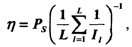
- Thus, if the first telecommunication device adjusts its transmission power differently in some frequency bands, the second telecommunication device is aware about each adjustment.
- According to a second mode of realisation of the present invention, the first telecommunication devices comprises M antennas, the second telecommunication device comprises N antennas and the measured interferences components are set, for at least the first and second frequency subbands, under the form of an interference correlation matrix RIN,l, where l denotes the indicia of the first and second frequency subbands, and the determination, for each first and second frequency subbands, of the at least one first and second weights from the measured interference components is decomposed into :
- executing an eigenvalue decomposition of the interference correlation matrix


- determining, for the first and second frequency subbands respectively at most M weighting vectors gl,m from at least the first and the second matrices, where m=1 to at most M,
- weighting each of the at most M pilot signals by a respective weighting vector.
- Thus, the first telecommunication device can report information related to interference components it receives in some frequency subbands to a second telecommunication device without decreasing the bandwidth which is used for classical data transmission.
- Furthermore, the present invention is also adapted for systems which combine multi frequency subbands and MIMO schemes.
- According to another advantageous embodiment, the at most M weighting vectors g l, 1 to gl,M are determined according to the following formula :

- Thus, the determination of the weighting vectors gl,1 to gl,M is simple fits with the spatial direction of the received interference components and their intensity.
- According to another advantageous embodiment, the first telecommunication device determines at least a power coefficient, weights the at most M pilot signals by the power coefficient and transfers to the second telecommunication device signals representing at least a power information which is related to the determined power coefficient.
- Thus, if the first telecommunication device adjusts its transmission power, the second telecommunication device is aware about that adjustment.
- According to another advantageous embodiment, a power coefficient


- According to another advantageous embodiment, a power coefficient ηl is determined for each first, second and for other frequency subbands according to the following formula :

- According to another advantageous embodiment, each frequency subband include plural subcarrier frequencies and the measured the interference components received by the first telecommunication device in the first frequency subband are the average of the interference components measured in each of the subcarrier frequencies of the first frequency subband and the measured the interference components received by the first telecommunication device in the second frequency subband are the average of the interference components measured in each of the subcarrier frequencies of the second frequency subband.
- Thus, the interference components measured in each subband frequency takes into account all the interference components received in each subcarrier frequency of a frequency subband.
- According to another advantageous embodiment, each frequency subband include plural subcarrier frequencies and the measured the interference components received by the first telecommunication device in the first frequency subband are the interference components measured in at least a subcarrier frequency of the first frequency subband and the measured the interference components received by the first telecommunication device in the second frequency subband the interference components measured in at least a subcarrier frequency of the first frequency subband.
- Thus, only some interference components measured in at least one subcarrier frequency is s taken into account.
- According to still another aspect, the present invention concerns a method for controlling the transfer of signals to a first telecommunication device by a second telecommunication device through a wireless network using multiple frequency subbands, characterised in the method comprises the steps executed by the second telecommunication device of :
- receiving from the first telecommunication device, at least a first pilot signal through a first frequency subband and at least a second pilot signal through a second frequency subband,
- determining, from the at least first pilot signal, information representative of interference components received by the first telecommunication device in the first frequency subband,
- determining, from the at least second pilot signal, information representative of interference components received by the first telecommunication device in the second frequency subband,
- controlling the transfer of signals representative of a group of data to the first telecommunication device according to the determined information representative of interference components received by the first telecommunication device.
- The present invention concerns also a device for controlling the transfer of signals to a first telecommunication device by a second telecommunication device through a wireless network using multiple subbands, characterised in the device for controlling the transfer of signals is included in the second telecommunication device and comprises :
- means for receiving, from the first telecommunication device, at least a first pilot signal through a first frequency subband and at least a second pilot signal through a second frequency subband,
- means for determining, from the at least first pilot signal, information representative of interference components received by the first telecommunication device in the first frequency subband,
- means for determining, from the at least second pilot signal, information representative of interference components received by the first telecommunication device in the second frequency subband,
- means for controlling the transfer of signals representative of a group of data to the first telecommunication device according to the determined information representative of interference components received by the first telecommunication device.
- Thus, the second telecommunication device is informed about the interference components received by the first telecommunication device in some frequency subbands without decreasing in an important manner the bandwidth which is used for classical data transmission and can then reduce the effect of the interference components on the transferred signals representative of a group of information.
- According to the first mode of realisation of the present invention, the first telecommunication device and the second telecommunication device comprise one antenna, and the second telecommunication device receives, from the first telecommunication device, signals representing at least a power information and the information representative of interference components received by the first telecommunication device is determined from the at least first and second pilot signals and the at least one power information.
- Thus, if the first telecommunication adjusts its transmission power, the second telecommunication device is aware about that adjustment.
- According to another advantageous embodiment, the control of the transfer of signals representative of a group of data to the first telecommunication device is the determination of the transmission power to be used for transferring at least a group of data to the first telecommunication device.
- Thus the second telecommunication device can reduce the effect of the interference components received by the first telecommunication device.
- According to another advantageous embodiment, the control of the transfer of signals representative of a group of data to the first telecommunication device is the determination of the modulation and coding scheme to be used for transferring signals representative of the group of data to the first telecommunication device.
- Thus, the resources of the wireless telecommunication network system are used efficiently.
- According to another advantageous embodiment, plural first telecommunication devices transfer at least a first and second pilot signals and signals representative of at least a power information and in that the control of the transfer of signals representative of the group of data to the first telecommunication device is the determination to which first telecommunication device or devices among the plural first telecommunication devices, signals representing at least a group of data have to be transferred.
- Thus, the resources of the wireless telecommunication network system are used efficiently.
- Furthermore, the present invention is also adapted for systems which combine multi frequency subbands and MIMO schemes.
- According to the second mode of realisation of the present invention, the second telecommunication device comprises N antennas and the determined information representative of interference components received by a first telecommunication device in each first and second frequency subbands are a first and a second weighting vectors and in that the control of the transfer of signals representative of a group of data to the first telecommunication device in the first and second frequency subbands is made by weighting the signals representative of the group of data respectively by the first and the second weighting vectors.
- Thus, the second telecommunication device can direct the signals transfer to the first telecommunication device according to the interference components received by the first telecommunication device.
- According to another advantageous embodiment, the first telecommunication device comprises M antennas, at most M pilot signals are received in each first and second frequency subbands and each weighting vector is determined by :
- calculating a matrix Jl from the at most M received pilot signals, where l is an indicia of the first and second frequency subbands,
- executing, for each first and second frequency subband, an eigenvalue decomposition of the product of two matrices obtained from the calculated matrix in order to obtain eigenvectors and eigenvalues,
- selecting, for each first and second frequency subband, the eigenvector corresponding to the largest eigenvalue of the respective products of two matrices obtained from the calculated matrix.
- Thus, the present invention is also adapted for systems which combine multi frequency subbands and MIMO schemes.
- According to another advantageous embodiment, the product of two matrices obtained from the calculated matrix is equal to


- According to another advantageous embodiment, the second telecommunication device receives from the first telecommunication device, signals representing at least a power information and the information representative of interference components received by the first telecommunication device is determined from the at most M received pilot signals and the at least one power information.
- Thus, if the first telecommunication device adjusts its transmission power, the second telecommunication device is aware about that adjustment.
- According to another advantageous embodiment, the control of the transfer of signals representative of a group of data to the first telecommunication device is the determination of the modulation and coding scheme to be used for transferring signals representative of a group of data to the first telecommunication device.
- According to another advantageous embodiment, plural first telecommunication devices transfer pilot signals and signals representative of a power information and the control of the transfer of signals representative of a group of data to the first telecommunication device is the determination to which first telecommunication device or devices among the plural first telecommunication devices signals representing at least a group of data have to be transferred.
- Thus, the resources of the wireless telecommunication network system are used efficiently.
- According to still another aspect, the present invention concerns computer programs which can be directly loadable into a programmable device, comprising instructions or portions of code for implementing the steps of the methods according to the invention, when said computer programs are executed on a programmable device.
- Since the features and advantages relating to the computers programs are the same as those set out above related to the methods and devices according to the invention, they will not be repeated here.
- According to still another aspect, the present invention concerns the signals transferred according to the present invention.
- Since the features and advantages relating to the signals are the same as those set out above related to the methods and devices according to the invention, they will not be repeated here.
- The characteristics of the invention will emerge more clearly from a reading of the following description of an example embodiment, the said description being produced with reference to the accompanying drawings, among which :
- Fig. 1 is a diagram representing the architecture of a first telecommunication system in which the present invention is implemented;
- Fig. 2 is a diagram representing the architecture of a first telecommunication device according to a first mode of realisation of the present invention which is used in the first telecommunication system;
- Fig. 3 is a diagram representing the architecture of the second telecommunication device according to the first mode of realisation of the present invention which is used in the first telecommunication system;
- Fig. 4 is an algorithm executed by the first telecommunication device according to the first mode of realisation of the present invention;
- Fig. 5 is an algorithm executed by the second telecommunication device according to the first mode of realisation of the present invention;
- Fig. 6 is a diagram representing the architecture of a second telecommunication system in which the present invention is implemented;
- Fig. 7 is a diagram representing the architecture of the first telecommunication device according to the second mode of realisation of the present invention which is used in the second telecommunication system;
- Fig. 8 is a diagram representing the architecture of a channel interface of the first telecommunication device according to the second mode of realisation of the present invention;
- Fig. 9 is a diagram representing the architecture of the second telecommunication device according to the second mode of realisation of the present invention which is used in the second telecommunication system;
- Fig. 10 is a diagram representing the architecture of a channel interface of the second telecommunication device according to the second mode of realisation of the present invention;
- Fig. 11 is an algorithm executed by the first telecommunication device according to the second mode of realisation of the present invention;
- Fig. 12 is an algorithm executed by the second telecommunication device according to the second mode of realisation of the present invention.
- Fig. 1 is a diagram representing the architecture of a first telecommunication system in which the present invention is implemented.
- In the first telecommunication system of the Fig. 1, at least one
first telecommunication device wireless network 15 to asecond telecommunication device 10 using an uplink and a downlink channel. - Preferably, and in a non limitative way, the
second telecommunication device 10 is a base station or a node of thewireless network 15. Thefirst telecommunication devices 20l to 20K are terminals like mobile phones or personal computers. - The
telecommunication network 15 is a wireless telecommunication system which uses Time Division Duplexing scheme (TDD). The signals transferred in uplink and downlink channels are duplexed in different time periods of the same frequency band. The signals transferred within thewireless network 15 share the same frequency spectrum. The channel responses between the uplink and downlink channels of thetelecommunication network 15 are reciprocal. - Reciprocal means that if the downlink channel conditions are represented by a downlink matrix the uplink channel conditions can be expressed by an uplink matrix which is the transpose of the downlink matrix.
- The
first telecommunication network 15 is according to the present invention, a wireless telecommunication system which uses Orthogonal Frequency Division Multiplexing Access scheme (OFDMA). - In an OFDMA scheme, the overall system bandwidth is partitioned into L plural orthogonal frequency subbands, which are also referred to as frequency bins or subchannels. With OFDMA, each frequency subband is associated with respective subcarriers upon which data may be modulated.
- The
second telecommunication device 10 transfers signals representatives of a group of data to thefirst telecommunication devices 201 to 20K through the downlink channel and thefirst telecommunication devices 201 to 20K transfer signals to thesecond telecommunication device 10 through the uplink channel. - The
second telecommunication device 10 has one antenna BSAn. Thesecond telecommunication device 10 determines the modulation and coding scheme to be used for transferring groups of data to eachfirst telecommunication devices 20 and/or determines thefirst telecommunication device 20 to which, signals representative of a group of data have to be sent according to signals transferred by thefirst telecommunication devices 20 as it will be disclosed hereinafter. - The signals transferred by the
first telecommunication devices 20l to 20K are signals representatives of a group of data and/or pilot signals which are weighted by at least a weight determined from the interference components measured by thefirst telecommunication devices 20l to 20K. Eachfirst telecommunication device 20l to 20K has one antenna noted respectively MSAnl to MSAnK. - A group of data is as example a frame constituted at least by a header field and a payload field which comprises classical data like data related to a phone call, or a video transfer and so on.
- Pilot signals are predetermined sequences of symbols known by the telecommunication devices. Pilot signals are as example and in a non limitative way Walsh Hadamard sequences.
- Fig. 2 is a diagram representing the architecture of a first telecommunication device according to a first mode of realisation of the present invention which is used in the first telecommunication system.
- The
first telecommunication device 20, as example thefirst telecommunication device 20k with k comprised between l and K, has, for example, an architecture based on components connected together by abus 201 and aprocessor 200 controlled by programs related to the algorithm as disclosed in the Fig. 4. - It has to be noted here that the
first telecommunication device 20 is, in a variant, implemented under the form of one or several dedicated integrated circuits which execute the same operations as the one executed by theprocessor 200 as disclosed hereinafter. - The
bus 201 links theprocessor 200 to a read onlymemory ROM 202, a randomaccess memory RAM 203 and achannel interface 205. - The read only
memory ROM 202 contains instructions of the programs related to the algorithm as disclosed in the Fig. 4 which are transferred, when thefirst telecommunication device 20k is powered on to the randomaccess memory RAM 203. - The
RAM memory 203 contains registers intended to receive variables, and the instructions of the programs related to the algorithm as disclosed in the Fig. 4. - According to the first mode of realisation of the present invention, the
processor 200 determines, for at least two frequency subbands, and preferably for each of the l= l to L frequency subbands of the OFDMA system, a weighting coefficient noted
first telecommunication device 20k. - Each weighting coefficient

first telecommunication device 20k in the l-th frequency subband. - The interference components are electromagnetic waveforms generated by other first telecommunication devices, electromagnetic waveforms radiated by any electric equipment and/or any other noise received by the
first telecommunication device 20k. - Each weighting coefficient

second telecommunication device 10 through each of the at most L frequency subbands. - The
channel interface 205 comprises aninterference measurement module 210. When thesecond telecommunication device 10 transfers signals sl(p) with
first telecommunication device 20k in the l-th frequency subband is equal to
where hl, is the complex propagation gain in the frequency subband l between thesecond telecommunication device 10 and thefirst telecommunication device 20k and zl (p) is the interference component of thefirst telecommunication device 20k which has a power
- The
interference measurement module 210 determines, for each of the l=1 to L frequency subbands, the power Il of the interference components in the l-th frequency subband by averaging, in the l-th frequency subband,
- It has to be noted here that, the interferences components may vary in the different subcarrier frequencies included in a frequency subband. The interferences components in the subcarrier frequencies of a subband are then averaged.
- In a variant of realisation, instead of averaging the interference components in each subcarrier, the measured interference components in each frequency subband are the interference components measured in at least a subcarrier of a frequency subband, as example the largest interference components measured in a frequency carrier of a frequency subband.
- The
channel interface 205 comprises at most L multiplication modules. Preferably and in a non limitative way, thechannel interface 205 comprises L multiplication modules noted Mull to MulL which weight respectively the pilot signals Rl(p) to RL(p) by the respective weighting coefficients
- The
channel interface 205 comprises an Inverse Fast Fourier Transform module (IFFT) 220 which makes an inverse fast Fourier transform on each of the weighted pilot signals Rl(p) to at most RL(P). - The
channel interface 205 comprises a parallel toserial converter 230 which converted the at most L inversed Fourier transformed weighted pilot signals into signals transferred by the antenna MSAn. Thechannel interface 205 further comprises means for transferring a power information η to thesecond telecommunication device 10. - The power information η represents the multiplying factor used by the
first telecommunication device 20k for weighting the pilot signals. - It has to be noted here that, different power information can be determined for the L frequency subbands. In such case, each determined power information is transferred to the
second telecommunication device 10. - Fig. 3 is a diagram representing the architecture of the second telecommunication device according to the first mode of realisation of the present invention which is used in the first telecommunication system.
- The
second telecommunication device 10, has, for example, an architecture based on components connected together by abus 301 and aprocessor 300 controlled by programs as disclosed in the Fig. 5. - It has to be noted here that the
second telecommunication device 10 is, in a variant, implemented into one or several dedicated integrated circuits which execute the same operations as the one executed by theprocessor 300 as disclosed hereinafter. - The
bus 301 links theprocessor 300 to a read onlymemory ROM 302, a randomaccess memory RAM 303 and achannel interface 305. - The read only
memory ROM 302 contains instructions of the programs related to the algorithm as disclosed in the Fig. 5 which are transferred, when thesecond telecommunication 10 is powered on to the randomaccess memory RAM 303. - The
RAM memory 303 contains registers intended to receive variables, and the instructions of the programs related to the algorithm as disclosed in the Fig. 5. - According to the first mode of realisation of the present invention, the
processor 300 is able to determine from at least signals transferred by afirst telecommunication device 20k which are representative of pilot signals weighted by weighting coefficients
first telecommunication device 20k and/or to determine thefirst telecommunication device 20k to which signals representative of a group of data have to be sent according to signals transferred by thefirst telecommunication devices 20. - According to the first mode of realisation of the present invention, the
channel interface 305 comprises means for receiving at least one power information η from eachsecond telecommunication device 20. - Fig. 4 is an algorithm executed by the first telecommunication device according to the first mode of realisation of the present invention.
- The present algorithm is more precisely executed by each of the
first telecommunication devices 201 to 20K. - At step S400, the
processor 200 obtains from thechannel interface 205 the power Il, with l=1 to at most L, of the interference components of thefirst telecommunication device 20k in the at most L respective frequency subbands. - At next step S401, the
processor 200 determines the power information η which is representative of the transmit power. - At next step S402, the
processor 200 commands the transfer, by thechannel interface 305 of L uplink pilot signals
processor 200 transfers the power information η to thechannel interface 305 which transfers at least a signal representative of the power information η to thesecond telecommunication 10. - In a preferred mode of realisation of the present invention, the
processor 200 determines the power information η according to the following formula: -

- According to the invention, the SINR reporting is achieved by transmitting the pilot signal with a power which is inverse proportional to the interference power Il .
- Fig. 5 is an algorithm executed by the second telecommunication device according to the first mode of realisation of the present invention.
- At step S500, the signals transferred at step S402 by the
first telecommunication devices 20l to 20K, are received through thechannel interface 305 of thesecond telecommunication device 10. - In the reciprocal TDD system, the p-th symbol transferred by a
first telecommunication device 20k in the l-th subband by thesecond telecommunication device 10 is expressed as : -

second telecommunication device 10 in the l-th frequency subband. - At next step S501, the
processor 300 estimates the SINR of thefirst telecommunication devices 20 in each frequency subbands. The number of frequency subbands can either equal to two to L. - Using the power information η transferred by each
first telecommunication device 20 and thesecond telecommunication device 10 transmit power PBS,l, thesecond telecommunication device 10 predicts the SINR of each of thefirst telecommunication 20k in the l-th frequency subband as:
- If the uplink pilot signal in the l-th frequency subband is composed of p l symbols, with p l > 1, the SINR prediction is given by:

- In ideal condition with zA,l (p) = 0, we have

first telecommunication device 20k. - At next step S502, the
processor 300 determines the modulation and coding scheme to be used for the transfer of signals representative of groups of date to eachfirst telecommunication device 20k in the respective subbands using the determined SINR in each subbands. - In a variant of realisation, the
processor 300, using the determined SINR in each subbands, determines the transmission power PBS,l in each subband in order to adjust the SINR
- In another variant of realisation, the
processor 300 determines, using the determined SINR for all thefirst telecommunication devices 201 to 20K, thefirst telecommunication device 20 to which signals representative of a group of data have to be sent. - Fig. 6 is a diagram representing the architecture of a second telecommunication system in which the present invention is implemented.
- In the second telecommunication system of the Fig. 6, at least one
first telecommunication device 68k, with k=1 to K, is linked through awireless network 65 to asecond telecommunication device 60 using an uplink and a downlink channel. - Preferably, and in a non limitative way, the
second telecommunication device 60 is a base station or a node of thewireless network 65. Thefirst telecommunication devices 68l to 68K are terminals like mobile phones or personal computers. - The second telecommunication system is a wireless telecommunication system which uses OFDMA in combination with TDD and MIMO schemes. The signals transferred in uplink and downlink channels are duplexed in different time periods of same frequency bands. In an OFDMA scheme, the overall system bandwidth is partitioned into L plural orthogonal frequency subbands, which are also referred to as frequency bins or subchannels. With OFDMA, each frequency subband is associated with subcarriers upon which data may be modulated. The channel responses between the uplink and downlink channels of the
telecommunication network 65 are reciprocal. - Reciprocal means that if the downlink channel conditions are represented by a downlink matrix the uplink channel conditions can be expressed by an uplink matrix which is the transpose of the downlink matrix.
- The
second telecommunication device 60 transfers signals representatives of a group of data to thefirst telecommunication devices 68l to 68K through the downlink channel and thefirst telecommunication devices 68l to 68K transfer signals to thesecond telecommunication device 60 through the uplink channel. - The signals transferred by the
first telecommunication devices 68l to 68K are signals representatives of a group of data and/or pilot signals which are weighted by at least a weight determined from the interference components measured by thefirst telecommunication devices 68l to 68K. - A group of data is as example a frame constituted at least by a header field and a payload field which comprises classical data like data related to a phone call, or a video transfer and so on.
- Pilot signals are predetermined sequences of symbols known by the telecommunication devices. Pilot signals are as example and in a non limitative way Walsh Hadamard sequences.
- The
second telecommunication device 60 has at least one antenna and more preferably N antennas noted BSAntl to BSAntN. Thesecond telecommunication device 60 preferably controls the spatial direction of the signals transferred to each of thefirst telecommunication devices 68 according to at least signals transferred by thefirst telecommunication devices 68l to 68K as it will be disclosed hereinafter. - More precisely, when the
second telecommunication device 60 transmits signals representatives of a group of data to a givenfirst telecommunication device 68k through the downlink channel, the signals are at most L*N times duplicated and each duplicated signal is weighted, i.e. multiplied, by an element of a downlink weighting vector wn,l , with n=1 to at most N, of thesecond telecommunication device 60. As a result, thesecond telecommunication device 60 performs beamforming, i.e. controls the spatial direction of the transmitted signals. - The ellipse noted BF1 in the Fig. 6 shows the pattern of the radiated signals by the antennas BSAntl to BSAntN which are transferred to the
first telecommunication device 681 by thesecond telecommunication device 60. - The ellipse noted BFK in the Fig. 6 shows the pattern of the radiated signals by the antennas BSAnt1 to BSAntN which are transferred to the
first telecommunication device 68K by thesecond telecommunication device 60. - The
first telecommunication devices 68l to 68K have M antennas noted respectively MS1Ant1 to MS1AntM and MSKAnt1 to MSKAntM. It has to be noted here that the number M of antennas may vary according to eachfirst telecommunication device 68k with k=1 to K. Eachfirst telecommunication device 68l to 68k controls the spatial direction of the signals transferred to thesecond telecommunication device 60 as it will be disclosed hereinafter. - Each
first telecommunication device 68k transfers, through the antennas MSkAnt1 to MSkAntM, signals to be transmitted to thesecond telecommunication device 60. More precisely, when thefirst telecommunication device 68k transmits signals to thesecond telecommunication device 60 through the uplink channel, the signals are at most L*M times duplicated and each duplicated signal is weighted, i.e. multiplied, by an elements of uplink weighting vectors gm,l with l=1 to L, with m=1 to at most M of thefirst telecommunication device 68k. As a result, eachfirst telecommunication device 68k performs beamforming, i.e. controls the spatial direction of the transmitted signals. - The ellipse noted
BF 1 in the Fig. 6 shows the pattern of the radiated signals by the antennas MS1Ant1 to MS1AntM which are transferred by thefirst telecommunication device 68l to thesecond telecommunication device 60. - The ellipse noted BFK in the Fig. 6 shows the pattern of the radiated signals by the antennas MSKAnt1 to MSKAntM which are transferred by the
first telecommunication device 68K to thesecond telecommunication device 60. - Fig. 7 is a diagram representing the architecture of the first telecommunication device according to the second mode of realisation of the present invention which is used in the second telecommunication system.
- The
first telecommunication device 68, as example thefirst telecommunication device 68k with k comprised between 1 to K, has, for example, an architecture based on components connected together by abus 701 and aprocessor 700 controlled by programs related to the algorithm as disclosed in the Fig. 11. - It has to be noted here that the
first telecommunication device 68 is, in a variant, implemented under the form of one or several dedicated integrated circuits which execute the same operations as the one executed by theprocessor 700 as disclosed hereinafter. - The
bus 701 links theprocessor 700 to a read onlymemory ROM 702, a randomaccess memory RAM 703 and achannel interface 705. - The read only
memory ROM 702 contains instructions of the programs related to the algorithm as disclosed in the Fig. 11 which are transferred, when thefirst telecommunication device 68k is powered on to the randomaccess memory RAM 703. - The
RAM memory 703 contains registers intended to receive variables, and the instructions of the programs related to the algorithm as disclosed in the Fig. 11. - The
channel interface 705 comprises means for measuring the interference components measured by thefirst telecommunication device 68k, means for weighting the pilot signals to be transferred to thesecond telecommunication device 60 by at least a power coefficient
second telecommunication device 60 by weighting vectors gm,l , with m=1 to M, and means for transferring at least a power information ηl to thesecond telecommunication device 60. Thechannel interface 705 will be described in more detail in reference to the Fig. 8. - According to the present invention, the
processor 700 determines, from the interference components measured by thefirst telecommunication device 68k, at most M*L uplink weighting vectors gm,l to be used for weighting respectively at most M pilot signals to be transferred to thesecond telecommunication device 60 and determines a single power coefficient η or a power coefficient ηl for each of the l=1 to at most L subbands to be used for weighting the at most M pilot signals to be transferred to thesecond telecommunication device 60. - Fig. 8 is a diagram representing the architecture of a channel interface of the first telecommunication device according to the second mode of realisation of the present invention.
- The
channel interface 705 comprises aninterference measurement module 800 which measures the interference components measured by thefirst telecommunication device 68k. - The
interference measurement module 800 determines the interference correlation matrices RIN,l , with l=1 to L, of thefirst telecommunication device 20k which are respectively representative of the interferences components measured in each of the l = 1 to L frequency subbands of the MIMO-OFDMA system. - When the
second telecommunication device 60 transfers, in each of the L frequency subbands, a signal s l (p) with a power P BS,l and (E└|s l (p)|2┘ = 1, the p-th signal xl (p) received by thefirst telecommunication device 68k in the l-th frequency subband is equal to
where zl (p)=[z l,1(p),...,zl,M (p)]T is the interference plus noise vector of thefirst telecommunication 68k in the l-th frequency subband, Hl is the MIMO channel matrix in the l-th frequency subband. - The
interference measurement module 800 determines the interference correlation matrices RIN,l by averaging
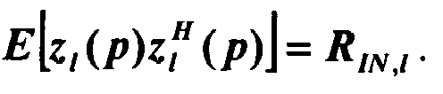
- The
channel interface 705 comprises L pilot signals processing devices noted 801l to 810L, M Inverse Fast Fourier Transform module (IFFT) noted 801l to 801M which make an inverse fast Fourier transform and M parallel to serial converters noted 8021 to 802M which converted the M inversed Fourier transformed signals into signals transferred to the respective antennas MSkAnt1 to MSkAntM. - The
channel interface 705 further comprises means for transferring at least a power information ηl to thesecond telecommunication device 60. - Each pilot signals
processing device 801l, with l=1 to L comprises M means for weighting M pilot signals noted Rl(t) to RM(t) to be transferred to thesecond telecommunication device 60 by a weighting coefficient
processing device 801l comprises M duplication modules noted CpI1U to CPMIU which duplicate the weighted pilot symbols and means for weighting the duplicated pilot signals to be transferred to thesecond telecommunication device 60 by weighting vectors gm,l . The means for weighting the weighted pilot signals to be transferred to thesecond telecommunication device 60 are composed of, M*M uplink multiplication modules noted MullllU to MulMlMU, M uplink summation modules noted SumllU to SumMlU. - Each duplicated pilot signal is weighted by the elements of a uplink weighting vector gm,l, with m=1 to M, determined by the
processor 700. - The signals weighted by the first element of each uplink weighting vector gm,l are then summed by the adder SumllU and transferred to the
IFFT module 8012. The signals weighted by the second element of each uplink weighting vector gm,l are then summed and transferred to theIFFT module 8012 and so on until the M-th element of the weighting vectors gm,l. - It has to be noted here that the signals are, prior to be transferred to each antenna MSkAnt1 to MSkAntM, frequency up converted, mapped and so on, as it is done in classical wireless telecommunication devices.
- It has to be noted here that, less than M pilot signals, as example M' pilot signals with M'≤M, can be transferred to the
second telecommunication 10 as it will be disclosed hereinafter. In such case, M-M' pilot signals are set to null value and/or their corresponding weighting vectors gm,l are also set to null value. - It has to be noted here that the pilot signals transferred in each frequency subband a identical, but we can understand that the pilot symbols used in a frequency subband can be different from the used in another or the other frequency subbands.
- Fig. 9 is a diagram representing the architecture of the second telecommunication device according to the second mode of realisation of the present invention which is used in the second telecommunication system.
- The
second telecommunication device 60 has, for example, an architecture based on components connected together by abus 901 and aprocessor 900 controlled by programs related to the algorithm as disclosed in the Fig. 12. - It has to be noted here that the
second telecommunication device 60 is, in a variant, implemented under the form of one or several dedicated integrated circuits which execute the same operations as the one executed by theprocessor 900 as disclosed hereinafter. - The
bus 901 links theprocessor 900 to a read onlymemory ROM 902, a randomaccess memory RAM 903 and achannel interface 905. - The read only
memory ROM 902 contains instructions of the programs related to the algorithm as disclosed in the Fig. 12 which are transferred, when thesecond telecommunication device 60 is powered on to the randomaccess memory RAM 903. - The
RAM memory 903 contains registers intended to receive variables, and the instructions of the programs related to the algorithm as disclosed in the Fig. 12. - According to the second mode of realisation of the present invention, the
processor 900 is able to determine from at least signals transferred by thefirst telecommunication device 68k which are representative of pilot signals weighted weighting coefficients
first telecommunication device 68k and/or to determine thefirst telecommunication device 68k to which signals representative of a group of data have to be sent according to signals transferred by thefirst telecommunication devices 60. - The
processor 900 is also able to determine, from at least signals transferred by eachfirst telecommunication device 681 to 68K which are representative of pilot signals weighted by the power coefficients
first telecommunication device 68k which has transferred the signals, the downlink weighting vectors wn,l to be used by thesecond telecommunication device 60 when it transfers signals to thefirst telecommunication device 68k which has transferred the signals. - According to the second mode of realisation of the present invention, the
channel interface 905 comprises means for receiving a power information η or plural power information ηl from each thesecond telecommunication device 68. - The
channel interface 905 comprises means for receiving weighted pilot signals from eachfirst telecommunication device 68l to 68K, means for receiving, from eachfirst telecommunication device 68l to 68K, a power information ηl for each frequency subband or a single power information η for all of the frequency subbands. Thechannel interface 905 comprises means for directing, using the downlink weighting vectors wn,l, the signals representatives of groups of data transferred by thesecond telecommunication device 60 to afirst telecommunication device 68l to 68K. Thechannel interface 905 will be disclosed in more details in reference to the Fig. 10. - Fig. 10 is a diagram representing the architecture of a channel interface of the second telecommunication device according to the second mode of realisation of the present invention.
- The
channel interface 905 of thesecond telecommunication device 10 comprises a pilotsignal reception module 1000. - The pilot
signal reception module 1000 comprises means for receiving pilot signals weighted according the present invention by thefirst telecommunication devices 68l to 68K and a power information ηl for each frequency subband or a single power information η for all of the frequency subbands from each of thefirst telecommunication devices 68l to 68K. - The
channel interface 905 comprises L signals processing devices noted 10101 to 1010L, N IFFT modules noted 10011 to 1001N and N parallel to serial converters noted 1002l to 1002N which converted the N inversed Fourier transformed signals into signals transferred to the respective antennas BSAnt1 to BSAntN. - Each signals
processing device 1010l, with l=1 to L, comprises N duplication modules noted Cp11D to CPN1D which duplicate the signals representative of a group of data and means for weighting the duplicated signals to be transferred to thefirst telecommunication devices 68 by weighting vectors wn,l. The means for weighting the weighted signals to be transferred to thefirst telecommunication devices 68 are composed of, N*N downlink multiplication modules noted MullllD to MulNlND, N downlink summation modules noted SumllD to SumNlD. - Each duplicated signal is weighted by the elements of a downlink weighting vector wn,l, with n=1 to N, determined by the
processor 900. - The signals weighted by the first element of each uplink weighting vector wn,l are then summed by the adder SumllD and transferred to the
IFFT module 10011. The signals weighted by the second element of each uplink weighting vector wn,l are then summed and transferred to theIFFT module 10012 and so on until the N-th element of the weighting vectors wn,l . - It has to be noted here that the signals are, prior to be transferred to each antenna BSAnt1 to BSAntN, frequency up converted, mapped and so on, as it is done in classical wireless telecommunication devices.
- It has to be noted here that, less than N groups of data, as example N' with N' ≤ N, can be transferred to the
first telecommunication devices 68 as it will be disclosed hereinafter. - In such case, the signals representative of N-N' groups of data are set to null value and/or their corresponding weighting vectors wn,l are also set to null value.
- Fig. 11 is an algorithm executed by the first telecommunication device according to the second mode of realisation of the present invention.
- The present algorithm is more precisely executed by each of the
first telecommunication devices 68l to 68K. - At step S 110, the
processor 700 receives the interference correlation matrices RIN,l ,with l=1 to L, of thefirst telecommunication device 68k which are respectively representative of the interferences generated by any other electric devices in each of the l= 1 to L frequency subbands of the MIMO-OFDM system. - At next step S111, the
processor 700 executes an eigenvalue decomposition of each of the interference correlation matrices
- At next step S 112, the
processor 700 determines the power information ηl for the l-th frequency subband with l=1 to L. The power information ηl can be set to any value or to a predetermined value known by all thetelecommunication devices - The
processor 700 determines the same power information η for all of the frequency subbands or determines a power information ηl for each subband. - When the same power information η is determined for all of the frequency subbands, η is preferably equal to

- When a power information ηl is determined for each frequency subband,

- At next step S113, the
processor 700 calculates the uplink weighting vectors

- In a variant of realisation, if some coefficients of the matrix Φ l are lower than a predetermined threshold, the
processor 700 doesn't transfer the corresponding uplink weighting vector to the channel interface. In such case, a reduced number of pilot signals needs then to be transferred to thesecond telecommunication device 60. - At next step S 114 the
processor 700 transfers the power information ηl or η and the uplink weighting vectors
channel interface 705. - At next step S115, the
processor 700 transfers at most M pilot signals to thechannel interface 705. The pilot signal rl,m(p), with m=1 to M, transferred has p 0 symbols which are mutually orthogonal as:
- At next step S 116, each of the at most M pilot signals are duplicating at most M times. Each duplicated pilot signal is weighted by the elements of an uplink weighting vector gl,m = [g l,m1,...,g l,mM ] T and transferred to the
second telecommunication device 60. - Fig. 12 is an algorithm executed by the second telecommunication device according to the second mode of realisation of the present invention.
- At step S120, the signals transferred at step S116 by at least a
first telecommunication device 68k, are received through thechannel interface 905 of thesecond telecommunication device 60. - In the l-th frequency subband, the p-th sample xBS,l(p) of the receive signal by the
second telecommunication device 60 is expressed as: -


first telecommunication devices 68k which sent the signals, Z BS,l (p) = [Z BS,l,1(p),...,Z BS,l,N (p)] T the N*1second telecommunication device 60 interference components and in the case of a reciprocal channel, the uplink channel is expressed as HT l using the downlink channel matrix Hl for the l-th subband. - At next step S121, the
processor 900 estimates, for each of the L frequency subbands, the product of matrices
- The received signals p = 1,..., p 0 are totally expressed in matrix form as:


where

- Then, the
processor 900 estimates

- At next step S122, the
processor 900 executes, for each of the L frequency subbands, an eigenvalue decomposition of
- At next step S 123, the
processor 900 determines, for each of the L frequency subbands, the largest eigenvalue noted
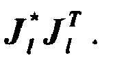
- It has to be noted here that, if at least two groups of data have to be transferred in parallel to the
first telecommunication device 68k, theprocessor 900 determines the at least two largest eigenvalues of the matrix
- At next step S124, the
processor 900 determines the downlink weighting vectors Wn,l with l=1 to L to be used in the respective l=1 to L frequency subbands for transferring signals representing a group of data to thefirst telecommunication device 68k which has transferred the signals received at step S120. - The downlink weighting vector Wn,l for the l-th frequency subband is the eigenvector noted

- If at least two groups of data have to be transferred in parallel to the first telecommunication device68k, the
processor 900 determines at least two downlink weighting vectors for each subband. Theprocessor 900 determines the downlink weighting vector wn,l for the l-th frequency subband, with n being equal or upper than 2, are the eigenvector noted which corresponds to largest the at least two eigenvalues. - At next step S125, the
processor 900 estimates, for each of the L frequency subbands, the SINR of thefirst telecommunication device 68k which has transferred the signals received at step S120. - Using the transmit power


- It has to be noted here that the
second telecommunication device 60 can direct the signals transferred to thefirst telecommunication device 68k which has transferred the signals received at step S120 considering the effect of interferences on thefirst telecommunication device 68k without having the complete knowledge of Hl and RIN,l. - At next step S126, the
processor 900 determines the modulation and coding scheme to be used for the transfer of signals representative of a group of data to thefirst telecommunication device 68k using the determined SINR or theprocessor 300 determines, using the predicted SINR of all thefirst telecommunication devices 681 to 68K, thefirst telecommunication device 68k to which signals representative of a group of data have to be sent. - In a variant of realisation, the
processor 900 adjusts the transmission power
- Naturally, many modifications can be made to the embodiments of the invention described above without departing from the scope of the present invention.
Claims (26)
- Method for reporting, through a wireless network using multiple frequency subbands, interference components received by a first telecommunication in a first and a second frequency subbands of the wireless network, to a second telecommunication device, characterised in that the method comprises the steps executed by the first telecommunication device of :- measuring the interference components received by the first telecommunication device in the first frequency subband and in the second frequency subband of the wireless network,- determining at least a first weight from the measured interference components in the first frequency subband and at least a second weight from the measured interference components in the second frequency subband,- weighting a first pilot signal with the at least one first determined weight and weighting a second pilot signal with the at least one second determined weight,- transferring the first weighted pilot signal through said first frequency subband and the second weighted pilot signal through said second frequency subband to the second telecommunication device.
- Method according to claim 1, characterised in that the first telecommunication device and the second telecommunication device comprise one antenna, and in that, the first and second determined weights are respectively inversely proportional to the interference components measured in the first and second frequency subbands.
- Method according to claim 2, characterised in that the method further comprises the steps of :- determining a power information for the first and second frequency subbands,- transferring to the second telecommunication device signals representing the power information.
- Method according to claim 2, characterised in that a power information is determined for each of the first and second frequency subbands and for other frequency subbands according to the following formula:

- Method according to any of the claims 1 to 4, characterised in that each frequency subband include plural subcarrier frequencies and in that the measured the interference components received by the first telecommunication device in the first frequency subband are the average of the interference components measured in each of the subcarrier frequencies of the first frequency subband and the measured the interference components received by the first telecommunication device in the second frequency subband are the average of the interference components measured in each of the subcarrier frequencies of the second frequency subband.
- Method according to any of the claims 1 to 4, characterised in that each frequency subband include plural subcarrier frequencies and the measured the interference components received by the first telecommunication device in the first frequency subband are the interference components measured in at least a subcarrier frequency of the first frequency subband and the measured the interference components received by the first telecommunication device in the second frequency subband the interference components measured in at least a subcarrier frequency of the first frequency subband.
- Method according to claim 1, characterised in that the first telecommunication devices comprises M antennas, the second telecommunication device comprises N antennas and in that the measured interferences components are set, for at least the first and second frequency subbands, under the form of an interference correlation matrix RIN,l , where l denotes the indicia of the first and second frequency subbands, and the determination, for each first and second frequency subbands, of the at least one first and second weights from the measured interference components is decomposed into sub-steps of :- executing an eigenvalue decomposition of the interference correlation matrix

 - determining, for the first and second frequency subbands respectively at most M weighting vectors gl,m from at least the first and the second matrices, where m=1 to at most M,- weighting each of the at most M pilot signals by a respective weighting vector.
 - Method according to claim 7, characterised in that the at most M weighting vectors gl,1 to gl,M are determined according to the following formula:

- Method according to claim 7, characterised in that the method further comprises the steps of :- determining at least a power coefficient,- weighting the at most M pilot signals by the power coefficient,- transferring to the second telecommunication device signals representing at least a power information which is related to the determined power coefficient.
- Method according to claim 9, characterised in that a power coefficient


- Method according to claim 9, characterised in that a power coefficient ηl , is determined for each the first, second and for other frequency subbands according to the following formula :

- Method for controlling the transfer of signals to a first telecommunication device by a second telecommunication device through a wireless network using multiple frequency subbands, characterised in the method comprises the steps executed by the second telecommunication device of :- receiving from the first telecommunication device, at least a first pilot signal through a first frequency subband and at least a second pilot signal through a second frequency subband,- determining, from the at least first pilot signal, information representative of interference components received by the first telecommunication device in the first frequency subband,- determining, from the at least second pilot signal, information representative of interference components received by the first telecommunication device in the second frequency subband,- controlling the transfer of signals representative of a group of data to the first telecommunication device according to the determined information representative of interference components received by the first telecommunication device.
- Method according to claim 12, characterised in that the first telecommunication device and the second telecommunication device comprise one antenna, and in that the method comprises further step of receiving, from the first telecommunication device, signals representing at least a power information and in that the information representative of interference components received by the first telecommunication device is determined from the at least first and second pilot signals and the at least one power information.
- Method according to claim 13, characterised in that the control of the transfer of signals representative of a group of data to the first telecommunication device is the determination of the transmission power to be used for transferring at least a group of data to the first telecommunication device.
- Method according to claim 13, characterised in that the control of the transfer of signals representative of a group of data to the first telecommunication device is the determination of the modulation and coding scheme to be used for transferring signals representative of the group of data to the first telecommunication device.
- Method according to any of the claims 14 or 15, characterised in that plural first telecommunication devices transfer at least a first and second pilot signals and signals representative of at least a power information and in that the control of the transfer of signals representative of the group of data to the first telecommunication device is the determination to which first telecommunication device or devices among the plural first telecommunication devices, signals representing at least a group of data have to be transferred.
- Method according to claim 12, characterised in that the second telecommunication device comprises N antennas and the determined information representative of interference components received by a first telecommunication device in each first and second frequency subbands are a first and a second weighting vectors and in that the control of the transfer of signals representative of a group of data to the first telecommunication device in the first and second frequency subbands is made by weighting the signals representative of the group of data respectively by the first and the second weighting vectors.
- Method according to claim 17, characterised in that the first telecommunication device comprises M antennas, at most M pilot signals are received in each first and second frequency subbands and in that each weighting vector is determined by :- calculating a matrix Jl from the at most M received pilot signals, where l is an indicia of the first and second frequency subbands,- executing, for each first and second frequency subband, an eigenvalue decomposition of the product of two matrices obtained from the calculated matrix in order to obtain eigenvectors and eigenvalues,- selecting, for each first and second frequency subband, the eigenvector corresponding to the largest eigenvalue of the respective products of two matrices obtained from the calculated matrix.
- Method according to claim 18, characterised in that the product of two matrices obtained from the calculated matrix is equal to


- Method according to any of the claims 17 to 19, characterised in that the method comprises further step of receiving from the first telecommunication device, signals representing at least a power information and in that the information representative of interference components received by the first telecommunication device is determined from the M received pilot signals and the at least one power information.
- Method according to claim 20, characterised in that the control of the transfer of signals representative of a group of data to the first telecommunication device is the determination of the modulation and coding scheme to be used for transferring signals representative of a group of data to the first telecommunication device.
- Method according to claim 20 or 21, characterised in that plural first telecommunication devices transfer pilot signals and signals representative of a power information and in that the control of the transfer of signals representative of a group of data to the first telecommunication device is the determination to which first telecommunication device or devices among the plural first telecommunication devices signals representing at least a group of data have to be transferred.
- Device for reporting, through a wireless network using multiple frequency subbands, interference components received by a first telecommunication in a first and a second frequency subbands of the wireless network, to a second telecommunication device, characterised in that the device for reporting interference components is included in first telecommunication device and comprises :- means for measuring the interference components received by the first telecommunication device in the first frequency subband and in the second frequency subband of the wireless network,- means for determining at least a first weight from the measured interference components in the first frequency subband and at least a second weight from the measured interference components in the second frequency subband,- means for weighting a first pilot signal with the at least one first determined weight and weighting a second pilot signal with the at least one second determined weight,- means for transferring the first weighted pilot signal through said first frequency subband and the second weighted pilot signal through said second frequency subband to the second telecommunication device.
- Device for controlling the transfer of signals to a first telecommunication device by a second telecommunication device through a wireless network using multiple subbands, characterised in the device for controlling the transfer of signals is included in the second telecommunication device and comprises :- means for receiving, from the first telecommunication device, at least a first pilot signal through a first frequency subband and at least a second pilot signal through a second frequency subband,- means for determining, from the at least first pilot signal, information representative of interference components received by the first telecommunication device in the first frequency subband,- means for determining, from the at least second pilot signal, information representative of interference components received by the first telecommunication device in the second frequency subband,- means for controlling the transfer of signals representative of a group of data to the first telecommunication device according to the determined information representative of interference components received by the first telecommunication device.
- Computer program which can be directly loadable into a programmable device, comprising instructions or portions of code for implementing the steps of the method according to claims 1 to 11, when said computer program is executed on a programmable device.
- Computer program which can be directly loadable into a programmable device, comprising instructions or portions of code for implementing the steps of the method according to claims 12 to 22, when said computer program is executed on a programmable device.
Priority Applications (5)
| Application Number | Priority Date | Filing Date | Title |
|---|---|---|---|
| EP05292815A EP1804409B1 (en) | 2005-12-27 | 2005-12-27 | Method and device for reporting information related to interference components received by a first telecommunication device in some frequency subbands to a second telecommunication device |
| AT05292815T ATE523978T1 (en) | 2005-12-27 | 2005-12-27 | METHOD AND DEVICE FOR NOTIFYING TO A SECOND TELECOMMUNICATIONS DEVICE INFORMATION RELATING TO INTERFERENCE COMPONENTS RECEIVED IN A FIRST TELECOMMUNICATIONS DEVICE IN CERTAIN FREQUENCY SUB-BANDS |
| US11/611,598 US7657229B2 (en) | 2005-12-27 | 2006-12-15 | Method and device for reporting information related to interference components received by a first telecommunication device in some frequency subbands to a second telecommunication device |
| CNA2006100644589A CN101026397A (en) | 2005-12-27 | 2006-12-26 | Method and device for reporting information related to interference components |
| JP2006352283A JP2007208966A (en) | 2005-12-27 | 2006-12-27 | Method and apparatus for reporting interference component, method and apparatus for controlling signal transfer, and computer program |
Applications Claiming Priority (1)
| Application Number | Priority Date | Filing Date | Title |
|---|---|---|---|
| EP05292815A EP1804409B1 (en) | 2005-12-27 | 2005-12-27 | Method and device for reporting information related to interference components received by a first telecommunication device in some frequency subbands to a second telecommunication device |
Publications (2)
| Publication Number | Publication Date |
|---|---|
| EP1804409A1 true EP1804409A1 (en) | 2007-07-04 |
| EP1804409B1 EP1804409B1 (en) | 2011-09-07 |
Family
ID=35985847
Family Applications (1)
| Application Number | Title | Priority Date | Filing Date |
|---|---|---|---|
| EP05292815A Expired - Lifetime EP1804409B1 (en) | 2005-12-27 | 2005-12-27 | Method and device for reporting information related to interference components received by a first telecommunication device in some frequency subbands to a second telecommunication device |
Country Status (5)
| Country | Link |
|---|---|
| US (1) | US7657229B2 (en) |
| EP (1) | EP1804409B1 (en) |
| JP (1) | JP2007208966A (en) |
| CN (1) | CN101026397A (en) |
| AT (1) | ATE523978T1 (en) |
Cited By (1)
| Publication number | Priority date | Publication date | Assignee | Title |
|---|---|---|---|---|
| WO2021113552A1 (en) * | 2019-12-04 | 2021-06-10 | Qualcomm Incorporated | Indicating a subband interference level using sounding reference signal |
Families Citing this family (11)
| Publication number | Priority date | Publication date | Assignee | Title |
|---|---|---|---|---|
| EP1804394A1 (en) * | 2005-12-27 | 2007-07-04 | Mitsubishi Electric Information Technology Centre Europe B.V. | Method and device for reporting information related to interference components received by a first telecommunication device to a second telecommunication device |
| EP1871017A1 (en) * | 2006-06-23 | 2007-12-26 | Mitsubishi Electric Information Technology Centre Europe B.V. | Method and device for reporting, through a wireless network, a channel state information between a first telecommunication device and a second telecommunication device |
| US8040278B2 (en) * | 2007-11-09 | 2011-10-18 | Intel Corporation | Adaptive antenna beamforming |
| TW200949750A (en) * | 2008-05-27 | 2009-12-01 | Inst Information Industry | Pre-loading system of personalized parameter and its method |
| US8711811B2 (en) * | 2008-06-19 | 2014-04-29 | Telefonaktiebolaget L M Ericsson (Publ) | Identifying multi-component carrier cells |
| GB2466070B (en) * | 2008-12-12 | 2014-04-30 | Nokia Corp | An apparatus |
| KR101532227B1 (en) * | 2008-12-18 | 2015-07-07 | 삼성전자주식회사 | A method of scheduling in a wireless communication system |
| US9048907B2 (en) | 2010-03-10 | 2015-06-02 | Alcatel Lucent | Methods for reducing interference in communication systems |
| US9661579B1 (en) * | 2013-05-03 | 2017-05-23 | Marvell International Ltd. | Per-tone power control in OFDM |
| WO2016119166A1 (en) * | 2015-01-29 | 2016-08-04 | Telefonaktiebolaget Lm Ericsson (Publ) | Methods for facilitating measurement at terminal device and associated radio base station and terminal device |
| US20260067011A1 (en) * | 2022-08-29 | 2026-03-05 | Nokia Technologies Oy | Interference weighting based subband selection procedure |
Citations (2)
| Publication number | Priority date | Publication date | Assignee | Title |
|---|---|---|---|---|
| WO2003001761A1 (en) * | 2001-06-22 | 2003-01-03 | Qualcomm Incorporated | Method and apparatus for transmitting data in a time division duplex system |
| WO2004038985A2 (en) * | 2002-10-25 | 2004-05-06 | Qualcomm Incorporated | Multi-mode terminal in a wireless mimo system with spatial multiplexing |
Family Cites Families (9)
| Publication number | Priority date | Publication date | Assignee | Title |
|---|---|---|---|---|
| JP2002261670A (en) * | 2001-02-27 | 2002-09-13 | Yrp Mobile Telecommunications Key Tech Res Lab Co Ltd | Wireless transmitting apparatus and wireless receiving apparatus |
| US7039363B1 (en) * | 2001-09-28 | 2006-05-02 | Arraycomm Llc | Adaptive antenna array with programmable sensitivity |
| KR100795824B1 (en) * | 2001-12-08 | 2008-01-17 | 주식회사 세스텍 | Signal processing method and apparatus for obtaining diversity gain in a communication system having an antenna array |
| US7362830B2 (en) * | 2002-12-31 | 2008-04-22 | Lg Electronics Inc. | Smart antenna system and method |
| JP4482293B2 (en) * | 2003-07-03 | 2010-06-16 | パナソニック株式会社 | Base station apparatus and transmission method |
| JP2005057497A (en) * | 2003-08-04 | 2005-03-03 | Science Univ Of Tokyo | Wireless transmission control method, wireless receiver, and wireless transmitter |
| US7457590B2 (en) * | 2003-12-23 | 2008-11-25 | Motorola, Inc. | Method, apparatus and system for use in the transmission of wireless communications using multiple antennas |
| US7194042B2 (en) * | 2004-01-13 | 2007-03-20 | Qualcomm Incorporated | Data transmission with spatial spreading in a mimo communication system |
| US8000418B2 (en) * | 2006-08-10 | 2011-08-16 | Cisco Technology, Inc. | Method and system for improving robustness of interference nulling for antenna arrays |
-
2005
- 2005-12-27 EP EP05292815A patent/EP1804409B1/en not_active Expired - Lifetime
- 2005-12-27 AT AT05292815T patent/ATE523978T1/en not_active IP Right Cessation
-
2006
- 2006-12-15 US US11/611,598 patent/US7657229B2/en not_active Expired - Fee Related
- 2006-12-26 CN CNA2006100644589A patent/CN101026397A/en active Pending
- 2006-12-27 JP JP2006352283A patent/JP2007208966A/en active Pending
Patent Citations (2)
| Publication number | Priority date | Publication date | Assignee | Title |
|---|---|---|---|---|
| WO2003001761A1 (en) * | 2001-06-22 | 2003-01-03 | Qualcomm Incorporated | Method and apparatus for transmitting data in a time division duplex system |
| WO2004038985A2 (en) * | 2002-10-25 | 2004-05-06 | Qualcomm Incorporated | Multi-mode terminal in a wireless mimo system with spatial multiplexing |
Non-Patent Citations (1)
| Title |
|---|
| MUENSTER M ET AL: "CO-CHANNEL INTERFERENCE SUPPRESSION ASSISTED ADAPTIVE OFDM IN INTERFERENCE LIMITED ENVIRONMENTS", VTC 1999-FALL. IEEE VTS 50TH. VEHICULAR TECHNOLOGY CONFERENCE. GATEWAY TO THE 21ST. CENTURY COMMUNICATIONS VILLAGE. AMSTERDAM, SEPT. 19 - 22, 1999, IEEE VEHICULAR TECHNOLGY CONFERENCE, NEW YORK, NY : IEEE, US, vol. VOL. 1 CONF. 50, September 1999 (1999-09-01), pages 284 - 288, XP000929056, ISBN: 0-7803-5436-2 * |
Cited By (2)
| Publication number | Priority date | Publication date | Assignee | Title |
|---|---|---|---|---|
| WO2021113552A1 (en) * | 2019-12-04 | 2021-06-10 | Qualcomm Incorporated | Indicating a subband interference level using sounding reference signal |
| US11212691B2 (en) | 2019-12-04 | 2021-12-28 | Qualcomm Incorporated | Indicating a subband interference level using sounding reference signal |
Also Published As
| Publication number | Publication date |
|---|---|
| ATE523978T1 (en) | 2011-09-15 |
| CN101026397A (en) | 2007-08-29 |
| EP1804409B1 (en) | 2011-09-07 |
| US20070157279A1 (en) | 2007-07-05 |
| US7657229B2 (en) | 2010-02-02 |
| JP2007208966A (en) | 2007-08-16 |
Similar Documents
| Publication | Publication Date | Title |
|---|---|---|
| US6927728B2 (en) | Method and apparatus for multi-antenna transmission | |
| EP1807990B1 (en) | Method and apparatus for closed loop data transmission | |
| US8130847B2 (en) | Closed-loop transmission feedback in wireless communication systems | |
| US8488704B2 (en) | Method for selecting subchannel mode and MIMO communication system using the same | |
| EP2523381A1 (en) | Method and system for frame formats for MIMO channel measurement exchange | |
| CN101675601B (en) | A kind of method for communicating in mimo context | |
| EP2448137A1 (en) | Method and device for signal transmission in time-division duplex mimo system | |
| EP1804409B1 (en) | Method and device for reporting information related to interference components received by a first telecommunication device in some frequency subbands to a second telecommunication device | |
| US7778605B2 (en) | Method and device for reporting information related to interference components received by a first telecommunication device to a second telecommunication device | |
| EP1871017A1 (en) | Method and device for reporting, through a wireless network, a channel state information between a first telecommunication device and a second telecommunication device | |
| US20100279699A1 (en) | Method and device for controlling channel state information transferred by a first telecommunication device to a second telecommunication device | |
| EP1780907B1 (en) | Method for controlling the transmission of signals | |
| EP2008381B1 (en) | Method for transferring power information used by a telecommunication device for weighting at least one pilot signal | |
| EP1760905A1 (en) | Method for controlling the transfer of signals from a first communication device to a second communication device through a wireless network |
Legal Events
| Date | Code | Title | Description |
|---|---|---|---|
| PUAI | Public reference made under article 153(3) epc to a published international application that has entered the european phase |
Free format text: ORIGINAL CODE: 0009012 |
|
| AK | Designated contracting states |
Kind code of ref document: A1 Designated state(s): AT BE BG CH CY CZ DE DK EE ES FI FR GB GR HU IE IS IT LI LT LU LV MC NL PL PT RO SE SI SK TR |
|
| AX | Request for extension of the european patent |
Extension state: AL BA HR MK YU |
|
| 17P | Request for examination filed |
Effective date: 20070818 |
|
| 17Q | First examination report despatched |
Effective date: 20070920 |
|
| AKX | Designation fees paid |
Designated state(s): AT BE BG CH CY CZ DE DK EE ES FI FR GB GR HU IE IS IT LI LT LU LV MC NL PL PT RO SE SI SK TR |
|
| RAP1 | Party data changed (applicant data changed or rights of an application transferred) |
Owner name: MITSUBISHI ELECTRIC R&D CENTRE EUROPE B.V. Owner name: MITSUBISHI DENKI KABUSHIKI KAISHA |
|
| GRAP | Despatch of communication of intention to grant a patent |
Free format text: ORIGINAL CODE: EPIDOSNIGR1 |
|
| RAP1 | Party data changed (applicant data changed or rights of an application transferred) |
Owner name: MITSUBISHI DENKI KABUSHIKI KAISHA Owner name: MITSUBISHI ELECTRIC R&D CENTRE EUROPE B.V. |
|
| RIN1 | Information on inventor provided before grant (corrected) |
Inventor name: HARA, YOSHITAKA, Inventor name: MOTTIER, DAVID, |
|
| GRAS | Grant fee paid |
Free format text: ORIGINAL CODE: EPIDOSNIGR3 |
|
| GRAA | (expected) grant |
Free format text: ORIGINAL CODE: 0009210 |
|
| REG | Reference to a national code |
Ref country code: GB Ref legal event code: FG4D |
|
| REG | Reference to a national code |
Ref country code: CH Ref legal event code: EP |
|
| REG | Reference to a national code |
Ref country code: IE Ref legal event code: FG4D |
|
| REG | Reference to a national code |
Ref country code: DE Ref legal event code: R096 Ref document number: 602005029861 Country of ref document: DE Effective date: 20111103 |
|
| REG | Reference to a national code |
Ref country code: NL Ref legal event code: VDEP Effective date: 20110907 |
|
| PG25 | Lapsed in a contracting state [announced via postgrant information from national office to epo] |
Ref country code: FI Free format text: LAPSE BECAUSE OF FAILURE TO SUBMIT A TRANSLATION OF THE DESCRIPTION OR TO PAY THE FEE WITHIN THE PRESCRIBED TIME-LIMIT Effective date: 20110907 Ref country code: SE Free format text: LAPSE BECAUSE OF FAILURE TO SUBMIT A TRANSLATION OF THE DESCRIPTION OR TO PAY THE FEE WITHIN THE PRESCRIBED TIME-LIMIT Effective date: 20110907 Ref country code: LT Free format text: LAPSE BECAUSE OF FAILURE TO SUBMIT A TRANSLATION OF THE DESCRIPTION OR TO PAY THE FEE WITHIN THE PRESCRIBED TIME-LIMIT Effective date: 20110907 |
|
| LTIE | Lt: invalidation of european patent or patent extension |
Effective date: 20110907 |
|
| PG25 | Lapsed in a contracting state [announced via postgrant information from national office to epo] |
Ref country code: LV Free format text: LAPSE BECAUSE OF FAILURE TO SUBMIT A TRANSLATION OF THE DESCRIPTION OR TO PAY THE FEE WITHIN THE PRESCRIBED TIME-LIMIT Effective date: 20110907 Ref country code: CY Free format text: LAPSE BECAUSE OF FAILURE TO SUBMIT A TRANSLATION OF THE DESCRIPTION OR TO PAY THE FEE WITHIN THE PRESCRIBED TIME-LIMIT Effective date: 20110907 Ref country code: SI Free format text: LAPSE BECAUSE OF FAILURE TO SUBMIT A TRANSLATION OF THE DESCRIPTION OR TO PAY THE FEE WITHIN THE PRESCRIBED TIME-LIMIT Effective date: 20110907 Ref country code: GR Free format text: LAPSE BECAUSE OF FAILURE TO SUBMIT A TRANSLATION OF THE DESCRIPTION OR TO PAY THE FEE WITHIN THE PRESCRIBED TIME-LIMIT Effective date: 20111208 Ref country code: AT Free format text: LAPSE BECAUSE OF FAILURE TO SUBMIT A TRANSLATION OF THE DESCRIPTION OR TO PAY THE FEE WITHIN THE PRESCRIBED TIME-LIMIT Effective date: 20110907 |
|
| REG | Reference to a national code |
Ref country code: AT Ref legal event code: MK05 Ref document number: 523978 Country of ref document: AT Kind code of ref document: T Effective date: 20110907 |
|
| PG25 | Lapsed in a contracting state [announced via postgrant information from national office to epo] |
Ref country code: BE Free format text: LAPSE BECAUSE OF FAILURE TO SUBMIT A TRANSLATION OF THE DESCRIPTION OR TO PAY THE FEE WITHIN THE PRESCRIBED TIME-LIMIT Effective date: 20110907 |
|
| PG25 | Lapsed in a contracting state [announced via postgrant information from national office to epo] |
Ref country code: IS Free format text: LAPSE BECAUSE OF FAILURE TO SUBMIT A TRANSLATION OF THE DESCRIPTION OR TO PAY THE FEE WITHIN THE PRESCRIBED TIME-LIMIT Effective date: 20120107 Ref country code: CZ Free format text: LAPSE BECAUSE OF FAILURE TO SUBMIT A TRANSLATION OF THE DESCRIPTION OR TO PAY THE FEE WITHIN THE PRESCRIBED TIME-LIMIT Effective date: 20110907 Ref country code: SK Free format text: LAPSE BECAUSE OF FAILURE TO SUBMIT A TRANSLATION OF THE DESCRIPTION OR TO PAY THE FEE WITHIN THE PRESCRIBED TIME-LIMIT Effective date: 20110907 |
|
| PGFP | Annual fee paid to national office [announced via postgrant information from national office to epo] |
Ref country code: FR Payment date: 20120110 Year of fee payment: 7 |
|
| PG25 | Lapsed in a contracting state [announced via postgrant information from national office to epo] |
Ref country code: PL Free format text: LAPSE BECAUSE OF FAILURE TO SUBMIT A TRANSLATION OF THE DESCRIPTION OR TO PAY THE FEE WITHIN THE PRESCRIBED TIME-LIMIT Effective date: 20110907 Ref country code: IT Free format text: LAPSE BECAUSE OF FAILURE TO SUBMIT A TRANSLATION OF THE DESCRIPTION OR TO PAY THE FEE WITHIN THE PRESCRIBED TIME-LIMIT Effective date: 20110907 Ref country code: NL Free format text: LAPSE BECAUSE OF FAILURE TO SUBMIT A TRANSLATION OF THE DESCRIPTION OR TO PAY THE FEE WITHIN THE PRESCRIBED TIME-LIMIT Effective date: 20110907 Ref country code: RO Free format text: LAPSE BECAUSE OF FAILURE TO SUBMIT A TRANSLATION OF THE DESCRIPTION OR TO PAY THE FEE WITHIN THE PRESCRIBED TIME-LIMIT Effective date: 20110907 Ref country code: EE Free format text: LAPSE BECAUSE OF FAILURE TO SUBMIT A TRANSLATION OF THE DESCRIPTION OR TO PAY THE FEE WITHIN THE PRESCRIBED TIME-LIMIT Effective date: 20110907 Ref country code: PT Free format text: LAPSE BECAUSE OF FAILURE TO SUBMIT A TRANSLATION OF THE DESCRIPTION OR TO PAY THE FEE WITHIN THE PRESCRIBED TIME-LIMIT Effective date: 20120109 |
|
| PGFP | Annual fee paid to national office [announced via postgrant information from national office to epo] |
Ref country code: DE Payment date: 20111216 Year of fee payment: 7 |
|
| PLBE | No opposition filed within time limit |
Free format text: ORIGINAL CODE: 0009261 |
|
| STAA | Information on the status of an ep patent application or granted ep patent |
Free format text: STATUS: NO OPPOSITION FILED WITHIN TIME LIMIT |
|
| PG25 | Lapsed in a contracting state [announced via postgrant information from national office to epo] |
Ref country code: DK Free format text: LAPSE BECAUSE OF FAILURE TO SUBMIT A TRANSLATION OF THE DESCRIPTION OR TO PAY THE FEE WITHIN THE PRESCRIBED TIME-LIMIT Effective date: 20110907 Ref country code: MC Free format text: LAPSE BECAUSE OF NON-PAYMENT OF DUE FEES Effective date: 20111231 |
|
| REG | Reference to a national code |
Ref country code: CH Ref legal event code: PL |
|
| 26N | No opposition filed |
Effective date: 20120611 |
|
| REG | Reference to a national code |
Ref country code: IE Ref legal event code: MM4A |
|
| REG | Reference to a national code |
Ref country code: DE Ref legal event code: R097 Ref document number: 602005029861 Country of ref document: DE Effective date: 20120611 |
|
| PG25 | Lapsed in a contracting state [announced via postgrant information from national office to epo] |
Ref country code: LI Free format text: LAPSE BECAUSE OF NON-PAYMENT OF DUE FEES Effective date: 20111231 Ref country code: CH Free format text: LAPSE BECAUSE OF NON-PAYMENT OF DUE FEES Effective date: 20111231 Ref country code: IE Free format text: LAPSE BECAUSE OF NON-PAYMENT OF DUE FEES Effective date: 20111227 |
|
| PG25 | Lapsed in a contracting state [announced via postgrant information from national office to epo] |
Ref country code: ES Free format text: LAPSE BECAUSE OF FAILURE TO SUBMIT A TRANSLATION OF THE DESCRIPTION OR TO PAY THE FEE WITHIN THE PRESCRIBED TIME-LIMIT Effective date: 20111218 |
|
| PG25 | Lapsed in a contracting state [announced via postgrant information from national office to epo] |
Ref country code: LU Free format text: LAPSE BECAUSE OF NON-PAYMENT OF DUE FEES Effective date: 20111227 |
|
| PG25 | Lapsed in a contracting state [announced via postgrant information from national office to epo] |
Ref country code: BG Free format text: LAPSE BECAUSE OF FAILURE TO SUBMIT A TRANSLATION OF THE DESCRIPTION OR TO PAY THE FEE WITHIN THE PRESCRIBED TIME-LIMIT Effective date: 20111207 |
|
| GBPC | Gb: european patent ceased through non-payment of renewal fee |
Effective date: 20121227 |
|
| REG | Reference to a national code |
Ref country code: FR Ref legal event code: ST Effective date: 20130830 |
|
| PG25 | Lapsed in a contracting state [announced via postgrant information from national office to epo] |
Ref country code: TR Free format text: LAPSE BECAUSE OF FAILURE TO SUBMIT A TRANSLATION OF THE DESCRIPTION OR TO PAY THE FEE WITHIN THE PRESCRIBED TIME-LIMIT Effective date: 20110907 |
|
| REG | Reference to a national code |
Ref country code: DE Ref legal event code: R119 Ref document number: 602005029861 Country of ref document: DE Effective date: 20130702 |
|
| PG25 | Lapsed in a contracting state [announced via postgrant information from national office to epo] |
Ref country code: DE Free format text: LAPSE BECAUSE OF NON-PAYMENT OF DUE FEES Effective date: 20130702 Ref country code: HU Free format text: LAPSE BECAUSE OF FAILURE TO SUBMIT A TRANSLATION OF THE DESCRIPTION OR TO PAY THE FEE WITHIN THE PRESCRIBED TIME-LIMIT Effective date: 20110907 |
|
| PG25 | Lapsed in a contracting state [announced via postgrant information from national office to epo] |
Ref country code: GB Free format text: LAPSE BECAUSE OF NON-PAYMENT OF DUE FEES Effective date: 20121227 Ref country code: FR Free format text: LAPSE BECAUSE OF NON-PAYMENT OF DUE FEES Effective date: 20130102 |