EP1804406A1 - A protective method for span-ring service in an optical network - Google Patents
A protective method for span-ring service in an optical network Download PDFInfo
- Publication number
- EP1804406A1 EP1804406A1 EP06742110A EP06742110A EP1804406A1 EP 1804406 A1 EP1804406 A1 EP 1804406A1 EP 06742110 A EP06742110 A EP 06742110A EP 06742110 A EP06742110 A EP 06742110A EP 1804406 A1 EP1804406 A1 EP 1804406A1
- Authority
- EP
- European Patent Office
- Prior art keywords
- ring
- node
- cross
- service
- path
- Prior art date
- Legal status (The legal status is an assumption and is not a legal conclusion. Google has not performed a legal analysis and makes no representation as to the accuracy of the status listed.)
- Ceased
Links
- 238000000034 method Methods 0.000 title claims abstract description 37
- 230000003287 optical effect Effects 0.000 title claims abstract description 27
- 230000001681 protective effect Effects 0.000 title 1
- 230000004224 protection Effects 0.000 claims abstract description 111
- 230000009977 dual effect Effects 0.000 claims description 3
- 230000032258 transport Effects 0.000 description 13
- 238000010586 diagram Methods 0.000 description 7
- 238000007726 management method Methods 0.000 description 6
- 238000004891 communication Methods 0.000 description 5
- 230000008569 process Effects 0.000 description 3
- 239000000835 fiber Substances 0.000 description 2
- 230000011664 signaling Effects 0.000 description 2
- 238000005516 engineering process Methods 0.000 description 1
- 238000012986 modification Methods 0.000 description 1
- 230000004048 modification Effects 0.000 description 1
Images


Classifications
-
- H—ELECTRICITY
- H04—ELECTRIC COMMUNICATION TECHNIQUE
- H04J—MULTIPLEX COMMUNICATION
- H04J14/00—Optical multiplex systems
- H04J14/02—Wavelength-division multiplex systems
- H04J14/0227—Operation, administration, maintenance or provisioning [OAMP] of WDM networks, e.g. media access, routing or wavelength allocation
-
- H—ELECTRICITY
- H04—ELECTRIC COMMUNICATION TECHNIQUE
- H04J—MULTIPLEX COMMUNICATION
- H04J14/00—Optical multiplex systems
- H04J14/02—Wavelength-division multiplex systems
- H04J14/0278—WDM optical network architectures
- H04J14/0283—WDM ring architectures
-
- H—ELECTRICITY
- H04—ELECTRIC COMMUNICATION TECHNIQUE
- H04J—MULTIPLEX COMMUNICATION
- H04J14/00—Optical multiplex systems
- H04J14/02—Wavelength-division multiplex systems
- H04J14/0278—WDM optical network architectures
- H04J14/0284—WDM mesh architectures
-
- H—ELECTRICITY
- H04—ELECTRIC COMMUNICATION TECHNIQUE
- H04J—MULTIPLEX COMMUNICATION
- H04J14/00—Optical multiplex systems
- H04J14/02—Wavelength-division multiplex systems
- H04J14/0278—WDM optical network architectures
- H04J14/0286—WDM hierarchical architectures
-
- H—ELECTRICITY
- H04—ELECTRIC COMMUNICATION TECHNIQUE
- H04J—MULTIPLEX COMMUNICATION
- H04J14/00—Optical multiplex systems
- H04J14/02—Wavelength-division multiplex systems
- H04J14/0287—Protection in WDM systems
- H04J14/0289—Optical multiplex section protection
-
- H—ELECTRICITY
- H04—ELECTRIC COMMUNICATION TECHNIQUE
- H04J—MULTIPLEX COMMUNICATION
- H04J14/00—Optical multiplex systems
- H04J14/02—Wavelength-division multiplex systems
- H04J14/0287—Protection in WDM systems
- H04J14/0293—Optical channel protection
- H04J14/0294—Dedicated protection at the optical channel (1+1)
-
- H—ELECTRICITY
- H04—ELECTRIC COMMUNICATION TECHNIQUE
- H04J—MULTIPLEX COMMUNICATION
- H04J14/00—Optical multiplex systems
- H04J14/02—Wavelength-division multiplex systems
- H04J14/0287—Protection in WDM systems
- H04J14/0293—Optical channel protection
- H04J14/0295—Shared protection at the optical channel (1:1, n:m)
-
- H—ELECTRICITY
- H04—ELECTRIC COMMUNICATION TECHNIQUE
- H04Q—SELECTING
- H04Q11/00—Selecting arrangements for multiplex systems
- H04Q11/0001—Selecting arrangements for multiplex systems using optical switching
- H04Q11/0062—Network aspects
-
- H—ELECTRICITY
- H04—ELECTRIC COMMUNICATION TECHNIQUE
- H04Q—SELECTING
- H04Q11/00—Selecting arrangements for multiplex systems
- H04Q11/0001—Selecting arrangements for multiplex systems using optical switching
- H04Q11/0062—Network aspects
- H04Q2011/0079—Operation or maintenance aspects
- H04Q2011/0081—Fault tolerance; Redundancy; Recovery; Reconfigurability
-
- H—ELECTRICITY
- H04—ELECTRIC COMMUNICATION TECHNIQUE
- H04Q—SELECTING
- H04Q11/00—Selecting arrangements for multiplex systems
- H04Q11/0001—Selecting arrangements for multiplex systems using optical switching
- H04Q11/0062—Network aspects
- H04Q2011/009—Topology aspects
- H04Q2011/0092—Ring
Definitions
- the present invention relates to the filed of optical communication technologies, and particularly to a method for protecting a cross-ring service in an optical network.
- the optical network topology has experienced an isolated node, a linear topology and a ring topology.
- Many networks have been provided with a topology of Mesh or quasi-Mesh Network.
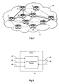
- An optical Network 10 as shown in Fig.1 includes a plurality of nodes 11 interconnected by a Mesh topology.
- the protection switching technique also has developed synchronously with the evolution of networks. ITU recommendations such as G.783, G.841, G.842 and the like provide protection methods applicable for a Link Network and a Ring Network, such as, MSP (Multiplex Section Protection) 1+1, MSP 1:n, UPSR (Unidirectional Path Switched Ring), BLSR (Bi-directional Line Switching Ring), etc., which have been used wildly.
- the protections for a transport plane mainly are a linear protection and a ring protection.
- the protection for a cross-ring (i.e. a protection ring) service mostly adopts a DNI (Dual-Node Interconnection) method.
- this DNI method relatively wastes resources and also has certain demands on the network structure, that is, a dual-node interconnection is generally required, and the configuration thereof is relatively complicated.
- Fig.2 shows a schematic diagram of a DNI protection with an SNCP (Sub Network Connection Protection), wherein a ring includes nodes 21, 22, 23 and a ring includes nodes 24, 25, 26 are interconnected via a pair of nodes 23, 24 and a pair of nodes 22, 25.
- each service is adapted to an SNCP service, where a dual-transmission of the service must be performed on an on-ring node and two interconnected nodes of a present ring, and a selective reception of the service can be performed on the two interconnected nodes of another ring and an off-node of the service of another ring.
- a method interconnecting rings with the Multiplex Section can provide such a protection.
- this method performs a service dual-transmission on interconnected local-ring nodes, and performs a selective reception on interconnected nodes at the same side of another ring.
- the configuration process for this method may be complicated which requires a manual configuration), and the bandwidth on a Multiplex Section ring may be occupied excessively (in particular when the interconnected nodes are not adjacent ones on the ring).
- this solution may be only applicable for the case of a dual-node interconnection, and fail to provide an effective protection for the case where the rings are interconnected merely via a single node or share no common node.
- the present invention provides a method for effectively protecting a cross-ring service in an optical network to overcome disadvantages of a low bandwidth utilization ratio and a strict requirement on the network topology in connection with the Dual-Node Interconnection method in the prior art used for the cross-ring service.
- An embodiment of the present invention provides a method for protecting a cross-ring service in an optical network, wherein the method may include the steps of:
- the method may further include the steps of:
- the cross-ring protection path may be established through Resource Reservation Protocol-Traffic Engineering Protocol, Open Shortest Path First-Traffic Engineering Protocol or Intermediate System-Intermediate System-Traffic Engineering Protocol.
- the method may further include the step of:
- the node for a selective reception may selectively receive a service on the working path and the cross-ring protection path.
- the node for a selective reception may selectively receive a service on an on-ring identical-direction protection path in the and the cross-ring protection path.
- the node for a selective reception may selectively receive a service on an on-ring opposite-direction protection path in the and the cross-ring protection path.
- a 1+1 or 1:1 protection may be adopted for the working path and the cross-ring protection path.
- the working path may cross rings interconnected via a single node or dual nodes or without a common node.
- a protection can be implemented for a service crossing rings interconnected via a single node.
- the embodiments of the present invention can reduce the occupancy of bandwidth resource on the Multiplex Section and improve the bandwidth utilization ratio.
- the embodiments of the present invention can provide a protection for a service crossing rings interconnected via dual nodes or without an interconnecting node, thus enabling an effective protection for a cross-ring service in an optical network.
- an optical network generally includes three logical planes, i.e. Transport Plane 33, Control Plane 32 and Management Plane 31. Control Plane 32 and Transport Plane 33 are connected respectively with Management Plane 31, and are connected with each other via Connection Control Interface 34.
- Transport Plane 33 includes transport network nodes 331 which are switching entities and interconnected through Sub Network Connection 332.
- Transport Plane 33 generally performs the functions of connecting/disconnecting, switching (routing), transporting and the like so as to provide a unidirectional or bi-directional information transport from one end point to another as well as a transport of some control information and network management information.
- Control Plane 32 performs the functions of call control, connection control and the like within an intelligent optical network.
- Control Plane 32 is supported by a signaling network and includes a plurality of functional components, such as a group of communication entities, Control Unit 322 (e.g. an optical connection controller) and a corresponding internal network node interface 324.
- Control Unit 322 respectively compose a plurality of Management Domains 321 interconnected via an external network node interface 323.
- the communication entities and Control Units 322 are primarily used for transferring a transport network resource and provide the functions related to establishing, maintaining and disconnecting (releasing the network resource) a connection. Among these functions, the functions of signaling and routing are the most important.
- Control Plane 32 is also connected to Request Proxy 36 via UNI (User Network Interface). A method for protecting a cross-ring service according to an embodiment of the present invention is implemented by Control Plane 32.
- Management Plane 31 manages Control Plane 32 and Transport Plane 33. While managing an optical transport network and the nodes 331, Management Plane 31 provides an efficient communication function between a network operation system and the nodes 331.
- Fig.4 is a schematic diagram of a service path according to an embodiment of the present invention.
- a solid line in the figure indicates a path with a ring protection, and a dashed line indicates a path without a ring protection.
- nodes A, B and E form a first ring
- nodes E, F, H, I, J and G form a second ring
- the first ring and the second ring are interconnected via single node E.
- a service goes via four nodes A, E, G and J.
- the service can obtain a good protection respectively in the first ring and the second ring.
- a service protection can be implemented via ABE, or when node G in the second ring fails, a service protection can be implemented via EFHIJ.
- interconnecting node E fails, the service can not obtain a good protection.
- the service cannot be protected even with a Dual-Node Interconnection (DNI) method, because there is one common node E between the two rings.
- DNI Dual-Node Interconnection
- Control Plane 32 When configuring a cross-ring protection path, Control Plane 32 firstly configures a working path, i.e. path AEGJ in Fig.4 (step S61).
- the configuration for the working path can be performed though Resource Reservation Protocol-Traffic Engineering (RSVP-TE) Protocol, Open Shortest Path First- Traffic Engineering (OSPF-TE) Protocol, Intermediate System-Intermediate System-Traffic Engineering (ISIS-TE) Protocol and the like of Generalized Multi-Protocol Label Switching (GMPLS).
- RSVP-TE Resource Reservation Protocol-Traffic Engineering
- OSPF-TE Open Shortest Path First- Traffic Engineering
- ISIS-TE Intermediate System-Intermediate System-Traffic Engineering
- GPLS Generalized Multi-Protocol Label Switching
- Control Plane 32 plans a cross-ring protection route at two adjacent nodes on the working path on both sides of node E that interconnects the two rings (through RSVP-TE, OSPF-TE or ISIS-TE Protocol), establishes a cross-ring protection path bypassing node E based upon a practical use status of bandwidth, and binds the cross-ring protection path and a corresponding section of the working path, wherein the corresponding section of the working path and the cross-ring protection path have the same origination node and include node E (step S63), as will be described in detail with reference to Fig.7.
- a cross-ring service 1+1 protection can be implemented through the cross-ring protection path (e.g. path AFG), wherein the service is transported simultaneously on two channels/links which do not intersect (the working channel/link and the protection channel/link), and thus those high-quality signals can be selected at the receiving end.
- 1:1 protection can also be implemented, wherein the service is only transported on the working channel/link, and the protection channel/link does not transport a service or transports a service with a low priority; and when the working channel/link fails, the service can be switched from the working channel/link to the protection channel/link, and the low-priority service on the protection channel/link may be dropped.
- a service protection (Multiplex Section protection) can be performed within the ring. Practically, the order of planning a Multiplex Section protection within a ring and planning a cross-ring protection path can be contrary to that as shown in Fig.6.
- a first node other than an off-ring node (node E in this embodiment), is selected in the first ring, and a second node, other than an on-ring node (also node E in this embodiment), is selected in the second ring.
- AF and FG have available bandwidth resources, and the first node can be node A and the second node can be node G, wherein the first node and the second node are located on the working path, i.e., path AEGJ (step S71).
- Control Plan 32 can establish a cross-ring protection path from the first node (node A) to the second node (node G) (step S72), and bind the cross-ring protection path AFG and the section AEG of the working path, and thus the 1+1 protection can be implemented for the path between AFG and AEG (step S73).
- the first node may be node A
- the second node may be node G
- the cross-ring protection path may be path ABG.
- the cross-ring protection path can include a plurality of intermediate nodes.
- the configuration for the protection path can be achieved through such techniques as OSPF-TE (Open Shortest Path First-Traffic Engineering) or the like based upon constraint information of each link, the use status of bandwidth and the like
- the service protection can also be achieved through the above method.
- the difference is that the off-ring node and the on-ring node are not coincident.
- path AFG the cross-ring protection path
- a dual-transmission of the service can be performed at node A
- a selective reception of the service can be performed at node G.
- path AFG may take the place of path AEG for a service path switching.
- a transfer for a point selectively receiving the service may be required, that is, node G is required to select a high-quality service for a selective reception from the service on protection channel E-F-H-I-J-G corresponding to working path EG after the switching and the service on path AFG, as detailed process in Fig.5.
- node G includes Service Transceiver Module 41, and is connected with a westward working channel 42, a westward protection channel 43 (a protection channel within the ring, which has an identical direction), an eastward working channel 45 and an eastward protection channel 46 (a protection channel within the ring, which has an opposite direction).
- the service when working channel AEGJ is in a normal status, the service is transported in the westward working channel 42; when the section switching occurs on section EG for the second ring EFHIJG, the service on working path AEGH may be switched to the westward protection channel 43, and all the services from G to J on the second ring EFHIJG may be transported on the eastward working channel 45; and when the ring switching occurs on section EG for the second ring EFHIJG, the service from E to G may be received on the eastward protection channel 46.
- node G is connected with the cross-ring protection channel 44 so as to achieve a protection for a cross-ring service when node E for interconnecting rings fails.
- node G receives selectively the services in Fig.4 the way as following: when no protection switching occurs on section EG of the second ring EFHIJG, Service Transceiver Module 41 selects and receives a service from the westward working channel 42 and the westward protection channel 43, and transfers the service to the eastward working channel 45; when the section protection switching occurs on section EG of the second ring EFHIJG, Service Transceiver Module 41 selects and receives a service from the westward protection channel 43 and the cross-ring protection channel 44, and transfers the service to the eastward working channel 45; and when the ring protection switching occurs on section EG of the second ring EFHIJG, Service Transceiver Module 41 selects and receives a service from the cross-ring protection channel 44 and the eastward protection channel 46, and transfers the service to the eastward working channel 45.
- the resource on path ABEFHIJ has to be occupied in order to achieve a protection for the service on cross-ring path AEGJ.
- the Multiplexing Section protection (protection for path ABE and protection for path EFHIJ, respectively) is also provided in each of the two rings (ring ABE and ring EGJIHF).
- the bandwidth on path ABEFHIJ has to be occupied twice that for the service.
- the method according to the embodiment of the present invention only adopts one service channel and one protection channel as described above, and therefore when working path AEGJ is in a normal status, the service is transferred in a working path and when the ring fails, a corresponding section switching is performed so as to switch the service on the failed working path to a corresponding protection path. Therefore, it is merely to occupy a service-corresponding bandwidth on working path AEGJ (or a corresponding protection path in the ring) or path AFG.
Landscapes
- Engineering & Computer Science (AREA)
- Computer Networks & Wireless Communication (AREA)
- Signal Processing (AREA)
- Small-Scale Networks (AREA)
- Optical Communication System (AREA)
Abstract
Description
- The present invention relates to the filed of optical communication technologies, and particularly to a method for protecting a cross-ring service in an optical network.
- The optical network topology has experienced an isolated node, a linear topology and a ring topology. At present, many networks have been provided with a topology of Mesh or quasi-Mesh Network. An
optical Network 10 as shown in Fig.1 includes a plurality ofnodes 11 interconnected by a Mesh topology. The protection switching technique also has developed synchronously with the evolution of networks. ITU recommendations such as G.783, G.841, G.842 and the like provide protection methods applicable for a Link Network and a Ring Network, such as, MSP (Multiplex Section Protection) 1+1, MSP 1:n, UPSR (Unidirectional Path Switched Ring), BLSR (Bi-directional Line Switching Ring), etc., which have been used wildly. - Although the Mesh Network topology has been used in an optical network system for some time, the protections for a transport plane mainly are a linear protection and a ring protection. The protection for a cross-ring (i.e. a protection ring) service mostly adopts a DNI (Dual-Node Interconnection) method. However, this DNI method relatively wastes resources and also has certain demands on the network structure, that is, a dual-node interconnection is generally required, and the configuration thereof is relatively complicated.
- Fig.2 shows a schematic diagram of a DNI protection with an SNCP (Sub Network Connection Protection), wherein a ring includes
nodes nodes nodes nodes - Also, a method interconnecting rings with the Multiplex Section can provide such a protection. Generally, this method performs a service dual-transmission on interconnected local-ring nodes, and performs a selective reception on interconnected nodes at the same side of another ring. The configuration process for this method may be complicated which requires a manual configuration), and the bandwidth on a Multiplex Section ring may be occupied excessively (in particular when the interconnected nodes are not adjacent ones on the ring). Moreover, this solution may be only applicable for the case of a dual-node interconnection, and fail to provide an effective protection for the case where the rings are interconnected merely via a single node or share no common node.
- The present invention provides a method for effectively protecting a cross-ring service in an optical network to overcome disadvantages of a low bandwidth utilization ratio and a strict requirement on the network topology in connection with the Dual-Node Interconnection method in the prior art used for the cross-ring service.
- An embodiment of the present invention provides a method for protecting a cross-ring service in an optical network, wherein the method may include the steps of:
- determining whether a configured working path crosses different rings; and
- in the case that the working path crosses different rings, establishing a cross-ring protection path which bypasses an off-ring node or an on-ring node of the working path on a ring, and binding the cross-ring protection path and the working path.
- Preferably, the method may further include the steps of:
- selecting a first node, other than the off-ring node, on a first ring including a service transmitting node, and selecting a second node, other than the on-ring node, on a second ring including a service receiving node, wherein the first node and the second node are located on the working path;
- establishing the cross-ring protection path with the first node being as an origination node and the second node being as a termination node; and
- binding the cross-ring protection path and a corresponding protected section of the working path, wherein the origination node and the termination node of the protected section are respectively the first node and the second node, and the protected section includes the off-ring node or the on-ring node.
- Preferably, the cross-ring protection path may be established through Resource Reservation Protocol-Traffic Engineering Protocol, Open Shortest Path First-Traffic Engineering Protocol or Intermediate System-Intermediate System-Traffic Engineering Protocol.
- Preferably, the method may further include the step of:
- a node for selectively receiving a service on the working path and the cross-ring protection path performing a transfer for a point of selectively receiving a service according to a ring switching status.
- Preferably, in the case that the ring in which the node for a selective reception is located operates normally, the node for a selective reception may selectively receive a service on the working path and the cross-ring protection path.
- Preferably, in the case that a section protection switching occurs to the ring in which the node for a selective reception is located, the node for a selective reception may selectively receive a service on an on-ring identical-direction protection path in the and the cross-ring protection path. Preferably, in the case that a ring protection switching occurs to the ring in which the node for a selective reception is located, the node for a selective reception may selectively receive a service on an on-ring opposite-direction protection path in the and the cross-ring protection path. Preferably, a 1+1 or 1:1 protection may be adopted for the working path and the cross-ring protection path.
- Preferably, the working path may cross rings interconnected via a single node or dual nodes or without a common node. According to the method for protecting a cross-ring service in an optical network in the embodiments of the present invention, with an establishment of a cross-ring protection path and a binding between the cross-ring protection path and a working path, a protection can be implemented for a service crossing rings interconnected via a single node. Moreover in comparison with the conventional Dual-Node Interconnection, the embodiments of the present invention can reduce the occupancy of bandwidth resource on the Multiplex Section and improve the bandwidth utilization ratio. In addition, the embodiments of the present invention can provide a protection for a service crossing rings interconnected via dual nodes or without an interconnecting node, thus enabling an effective protection for a cross-ring service in an optical network.
-
- FIG.1 is a schematic diagram of a Mesh Network topology in the prior art;
- FIG.2 is a schematic diagram of a Dual-Node Interconnection of a Sub Network Connection Protection ring according to the prior art;
- FIG.3 is a schematic diagram of a layered architecture of an optical network;
- FIG.4 is a schematic diagram of a service path according to an embodiment of the present invention;
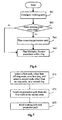
- FIG.5 is a structural schematic diagram of node G shown in Fig.4;
- FIG.6 is a flow chart of a method for protecting a cross-ring service in an optical network according to an embodiment of the present invention; and
- FIG.7 is a detailed flow chart of the step of planning a cross-ring protection path shown in Fig.6.
- The present invention will be further described hereinafter with reference to the drawings and the embodiments so as to make the principle, characteristics and advantages thereof more apparent.
- As shown in Fig.3, an optical network generally includes three logical planes, i.e.
Transport Plane 33,Control Plane 32 andManagement Plane 31.Control Plane 32 andTransport Plane 33 are connected respectively withManagement Plane 31, and are connected with each other viaConnection Control Interface 34. -
Transport Plane 33 includestransport network nodes 331 which are switching entities and interconnected through Sub NetworkConnection 332.Transport Plane 33 generally performs the functions of connecting/disconnecting, switching (routing), transporting and the like so as to provide a unidirectional or bi-directional information transport from one end point to another as well as a transport of some control information and network management information. -
Control Plane 32 performs the functions of call control, connection control and the like within an intelligent optical network.Control Plane 32 is supported by a signaling network and includes a plurality of functional components, such as a group of communication entities, Control Unit 322 (e.g. an optical connection controller) and a corresponding internalnetwork node interface 324. The communication entities and -
Control Unit 322 respectively compose a plurality ofManagement Domains 321 interconnected via an externalnetwork node interface 323. The communication entities andControl Units 322 are primarily used for transferring a transport network resource and provide the functions related to establishing, maintaining and disconnecting (releasing the network resource) a connection. Among these functions, the functions of signaling and routing are the most important. In addition,Control Plane 32 is also connected to RequestProxy 36 via UNI (User Network Interface). A method for protecting a cross-ring service according to an embodiment of the present invention is implemented by ControlPlane 32. -
Management Plane 31 managesControl Plane 32 andTransport Plane 33. While managing an optical transport network and thenodes 331,Management Plane 31 provides an efficient communication function between a network operation system and thenodes 331. - Fig.4 is a schematic diagram of a service path according to an embodiment of the present invention. A solid line in the figure indicates a path with a ring protection, and a dashed line indicates a path without a ring protection. As shown, nodes A, B and E form a first ring, nodes E, F, H, I, J and G form a second ring, and the first ring and the second ring are interconnected via single node E.
- It can be assumed that a service goes via four nodes A, E, G and J. The service can obtain a good protection respectively in the first ring and the second ring. For example, when fiber section AE in the first ring breaks, a service protection can be implemented via ABE, or when node G in the second ring fails, a service protection can be implemented via EFHIJ. However, if interconnecting node E fails, the service can not obtain a good protection. The service cannot be protected even with a Dual-Node Interconnection (DNI) method, because there is one common node E between the two rings.
- Referring to Fig.6, it is a flow chart of a method for protecting a cross-ring service in an optical network according to an embodiment of the present invention. When configuring a cross-ring protection path,
Control Plane 32 firstly configures a working path, i.e. path AEGJ in Fig.4 (step S61). The configuration for the working path can be performed though Resource Reservation Protocol-Traffic Engineering (RSVP-TE) Protocol, Open Shortest Path First- Traffic Engineering (OSPF-TE) Protocol, Intermediate System-Intermediate System-Traffic Engineering (ISIS-TE) Protocol and the like of Generalized Multi-Protocol Label Switching (GMPLS). Upon completion of the working path configuration,Control Plane 32 determines whether the working path crosses different rings, i.e., whether a service transmitting node and a service receiving node are located in the same ring (step S62). - If the service transmitting node and the service receiving node are located in the same ring, it goes to step S65 of planning a Multiplex Section protection respectively within the two rings, otherwise
Control Plane 32 plans a cross-ring protection route at two adjacent nodes on the working path on both sides of node E that interconnects the two rings (through RSVP-TE, OSPF-TE or ISIS-TE Protocol), establishes a cross-ring protection path bypassing node E based upon a practical use status of bandwidth, and binds the cross-ring protection path and a corresponding section of the working path, wherein the corresponding section of the working path and the cross-ring protection path have the same origination node and include node E (step S63), as will be described in detail with reference to Fig.7. When the common node of the two rings (node E in Fig.4) fails, a cross-ring service 1+1 protection can be implemented through the cross-ring protection path (e.g. path AFG), wherein the service is transported simultaneously on two channels/links which do not intersect (the working channel/link and the protection channel/link), and thus those high-quality signals can be selected at the receiving end. 1:1 protection can also be implemented, wherein the service is only transported on the working channel/link, and the protection channel/link does not transport a service or transports a service with a low priority; and when the working channel/link fails, the service can be switched from the working channel/link to the protection channel/link, and the low-priority service on the protection channel/link may be dropped. When a fiber breaks somewhere in the ring, a service protection (Multiplex Section protection) can be performed within the ring. Practically, the order of planning a Multiplex Section protection within a ring and planning a cross-ring protection path can be contrary to that as shown in Fig.6. - Referring to Fig.7, it is a detailed flow chart of step of planning a cross-ring protection path shown in Fig.6. Firstly, a first node, other than an off-ring node (node E in this embodiment), is selected in the first ring, and a second node, other than an on-ring node (also node E in this embodiment), is selected in the second ring. Referring to Fig.4, it can be assumed that AF and FG have available bandwidth resources, and the first node can be node A and the second node can be node G, wherein the first node and the second node are located on the working path, i.e., path AEGJ (step S71).
Control Plan 32 can establish a cross-ring protection path from the first node (node A) to the second node (node G) (step S72), and bind the cross-ring protection path AFG and the section AEG of the working path, and thus the 1+1 protection can be implemented for the path between AFG and AEG (step S73). - Practically, if AB and BG have available bandwidth resources, then the first node may be node A, the second node may be node G, and the cross-ring protection path may be path ABG. In addition to the first node and the second node, the cross-ring protection path can include a plurality of intermediate nodes. The configuration for the protection path can be achieved through such techniques as OSPF-TE (Open Shortest Path First-Traffic Engineering) or the like based upon constraint information of each link, the use status of bandwidth and the like
- In addition, when the service is transported through rings which are adjacent indirectly, the service protection can also be achieved through the above method. The difference is that the off-ring node and the on-ring node are not coincident.
- It can be assumed that the cross-ring protection path is path AFG, and a dual-transmission of the service can be performed at node A, and a selective reception of the service can be performed at node G. When the common node E of the first ring and the second ring fails, path AFG may take the place of path AEG for a service path switching.
- When a section switching or ring switching occurs due to a failure of section EG for the second multiplex ring EFHIJG, a transfer for a point selectively receiving the service may be required, that is, node G is required to select a high-quality service for a selective reception from the service on protection channel E-F-H-I-J-G corresponding to working path EG after the switching and the service on path AFG, as detailed process in Fig.5.
- In Fig.5, node G includes
Service Transceiver Module 41, and is connected with a westward workingchannel 42, a westward protection channel 43 (a protection channel within the ring, which has an identical direction), an eastward workingchannel 45 and an eastward protection channel 46 (a protection channel within the ring, which has an opposite direction). Here, when working channel AEGJ is in a normal status, the service is transported in the westward workingchannel 42; when the section switching occurs on section EG for the second ring EFHIJG, the service on working path AEGH may be switched to thewestward protection channel 43, and all the services from G to J on the second ring EFHIJG may be transported on the eastward workingchannel 45; and when the ring switching occurs on section EG for the second ring EFHIJG, the service from E to G may be received on theeastward protection channel 46. In addition, node G is connected with thecross-ring protection channel 44 so as to achieve a protection for a cross-ring service when node E for interconnecting rings fails. - Therefore, node G receives selectively the services in Fig.4 the way as following: when no protection switching occurs on section EG of the second ring EFHIJG,
Service Transceiver Module 41 selects and receives a service from the westward workingchannel 42 and thewestward protection channel 43, and transfers the service to the eastward workingchannel 45; when the section protection switching occurs on section EG of the second ring EFHIJG,Service Transceiver Module 41 selects and receives a service from thewestward protection channel 43 and thecross-ring protection channel 44, and transfers the service to the eastward workingchannel 45; and when the ring protection switching occurs on section EG of the second ring EFHIJG,Service Transceiver Module 41 selects and receives a service from thecross-ring protection channel 44 and theeastward protection channel 46, and transfers the service to the eastward workingchannel 45. - As shown in Fig.4, in the case of using the conventional
- Dual-Node Interconnection, the resource on path ABEFHIJ has to be occupied in order to achieve a protection for the service on cross-ring path AEGJ. Moreover, the Multiplexing Section protection (protection for path ABE and protection for path EFHIJ, respectively) is also provided in each of the two rings (ring ABE and ring EGJIHF). Thus, in order to achieve the protection for the service on cross-ring path AEGJ, the bandwidth on path ABEFHIJ has to be occupied twice that for the service. However, the method according to the embodiment of the present invention only adopts one service channel and one protection channel as described above, and therefore when working path AEGJ is in a normal status, the service is transferred in a working path and when the ring fails, a corresponding section switching is performed so as to switch the service on the failed working path to a corresponding protection path. Therefore, it is merely to occupy a service-corresponding bandwidth on working path AEGJ (or a corresponding protection path in the ring) or path AFG.
- The present invention has been described and illustrated by way of the embodiments of the present invention with reference to the drawings, it shall be recognized by those skilled in the art that those embodiments and drawings are merely illustrative and not restrictive, that the present invention shall be not limited thereto, and that various modifications and variations can be made thereto in light of the descriptions and the drawings without departing from the sprit and scope of the present invention as defined by the accompanying claims.
Claims (9)
- A method for protecting a cross-ring service in an optical network, wherein comprising the steps of:determining whether a configured working path crosses different rings; andin the case that the working path crosses different rings, establishing a cross-ring protection path which bypasses an off-ring node or an on-ring node of the working path on a ring, and binding the cross-ring protection path and the working path.
- A method for protecting a cross-ring service in an optical network according to claim 1, wherein further comprising the steps of:selecting a first node, other than the off-ring node, on a first ring comprising a service transmitting node, and selecting a second node, other than the on-ring node, on a second ring comprising a service receiving node, the first node and the second node being located on the working path;establishing the cross-ring protection path with the first node being as an origination node and the second node being as a termination node; andbinding the cross-ring protection path and a corresponding protected section of the working path, wherein the origination node and the termination node of the protected section are respectively the first node and the second node, and the protected section comprises the off-ring node or the on-ring node.
- A method for protecting a cross-ring service in an optical network according to claim 1, wherein the cross-ring protection path is established through Resource Reservation Protocol-Traffic Engineering Protocol, Open Shortest Path First-Traffic Engineering Protocol or Intermediate System-Intermediate System-Traffic Engineering Protocol.
- A method for protecting a cross-ring service in an optical network according to claim 1, further comprising the step of:a node for selectively receiving a service on the working path and the cross-ring protection path performing a transfer for a point of selectively receiving a service according to a ring switching status.
- A method for protecting a cross-ring service in an optical network according to claim 4, further comprising the step of:in the case that the ring in which the node for a selective reception is located operates normally, the node for a selective reception selectively receiving a service on the working path and the cross-ring protection path.
- A method for protecting a cross-ring service in an optical network according to claim 4, wherein in the case that a section protection switching occurs to the ring in which the node for a selective reception is located, the node for a selective reception selectively receives a service on an on-ring identical-direction protection path and the cross-ring protection path.
- A method for protecting a cross-ring service in an optical network according to claim 4, wherein in the case that a ring protection switching occurs to the ring in which the node for a selective reception is located, the node for a selective reception selectively receives a service on an on-ring opposite-direction protection path and the cross-ring protection path.
- A method for protecting a cross-ring service in an optical network according to claim 1, wherein a 1+1 or 1:1 protection is adopted for the working path and the cross-ring protection path.
- A method for protecting a cross-ring service in an optical network according to claim 1, wherein the working path crosses rings interconnected via a single node or dual nodes or without a common node.
Applications Claiming Priority (2)
| Application Number | Priority Date | Filing Date | Title |
|---|---|---|---|
| CNB2005100358741A CN100459553C (en) | 2005-07-06 | 2005-07-06 | Protection method for cross-ring service in optical transport network |
| PCT/CN2006/001224 WO2007003091A1 (en) | 2005-07-06 | 2006-06-06 | A protective method for span-ring service in an optical network |
Publications (2)
| Publication Number | Publication Date |
|---|---|
| EP1804406A1 true EP1804406A1 (en) | 2007-07-04 |
| EP1804406A4 EP1804406A4 (en) | 2008-04-23 |
Family
ID=37597908
Family Applications (1)
| Application Number | Title | Priority Date | Filing Date |
|---|---|---|---|
| EP06742110A Ceased EP1804406A4 (en) | 2005-07-06 | 2006-06-06 | A protective method for span-ring service in an optical network |
Country Status (4)
| Country | Link |
|---|---|
| US (1) | US7639944B2 (en) |
| EP (1) | EP1804406A4 (en) |
| CN (2) | CN100459553C (en) |
| WO (1) | WO2007003091A1 (en) |
Cited By (1)
| Publication number | Priority date | Publication date | Assignee | Title |
|---|---|---|---|---|
| EP2750336A4 (en) * | 2011-11-03 | 2014-12-10 | Zte Corp | Inter-loop service protection method and apparatus |
Families Citing this family (7)
| Publication number | Priority date | Publication date | Assignee | Title |
|---|---|---|---|---|
| WO2008080418A1 (en) * | 2006-12-28 | 2008-07-10 | Telefonaktiebolaget Lm Ericsson (Publ) | Protection scheme |
| KR100875934B1 (en) * | 2007-06-25 | 2008-12-26 | 한국전자통신연구원 | Multiring network operation method and device |
| US8203932B2 (en) * | 2008-12-02 | 2012-06-19 | Electronics And Telecommunications Research Institute | Method and system for protection switching in ethernet ring |
| CN101877665B (en) * | 2009-04-29 | 2013-12-18 | 华为技术有限公司 | Ring network protection method, network node and ring network |
| US8977123B2 (en) * | 2011-08-17 | 2015-03-10 | Nec Laboratories America, Inc. | 2-step-optimization procedure for routing and wavelength assignment with combined dedicated shared protections in multi-cable multi-fiber optical WDM networks |
| US9246627B2 (en) * | 2011-08-17 | 2016-01-26 | Nec Laboratories America, Inc. | Joint optimization procedure for routing and wavelength assignment with combined dedicated shared protections in multi-cable multi-fiber optical WDM networks |
| CN102546425B (en) * | 2012-01-31 | 2014-11-05 | 华为技术有限公司 | Crossed ring network protection method, equipment and system |
Family Cites Families (14)
| Publication number | Priority date | Publication date | Assignee | Title |
|---|---|---|---|---|
| JPH07264227A (en) | 1994-03-18 | 1995-10-13 | Fujitsu Ltd | Complex ring network control method |
| US6088141A (en) | 1995-06-26 | 2000-07-11 | Telefonaktiebolaget Lm Ericsson | Self-healing network |
| US5986783A (en) * | 1997-02-10 | 1999-11-16 | Optical Networks, Inc. | Method and apparatus for operation, protection, and restoration of heterogeneous optical communication networks |
| US6188668B1 (en) * | 1998-05-01 | 2001-02-13 | Emulex Corporation | Automatic isolation in loops |
| US6331905B1 (en) | 1999-04-01 | 2001-12-18 | The Trustees Of Columbia University In The City Of New York | Network switch failure restoration |
| US7167444B1 (en) * | 1999-12-29 | 2007-01-23 | At&T Corp. | Family ring protection technique |
| EP1217775A3 (en) | 2000-12-19 | 2005-10-19 | Nortel Networks Limited | Shared protection in an optical network |
| US8625411B2 (en) * | 2001-07-20 | 2014-01-07 | Bay Microsystems, Inc. | Robust mesh transport network comprising conjoined rings |
| US7082135B2 (en) | 2002-02-04 | 2006-07-25 | General Instrument Corporation | Extendable slot addressing system and method |
| CN100353716C (en) * | 2003-01-22 | 2007-12-05 | 华为技术有限公司 | Method of switching routes by setting up and deleting fork marker |
| DE60307230T2 (en) * | 2003-04-22 | 2007-07-05 | Alcatel Lucent | A method of using total resource capacity in an SDH network with an antiskid mechanism, in the presence of a packet-oriented data network, and associated apparatus for performing the method |
| WO2005008392A2 (en) * | 2003-07-08 | 2005-01-27 | Sycamore Networks, Inc. | Network span protection using span identifiers |
| CN100440843C (en) * | 2004-05-12 | 2008-12-03 | 华为技术有限公司 | Ring net and method for realizing service |
| CN100452751C (en) * | 2005-05-31 | 2009-01-14 | Ut斯达康通讯有限公司 | Method and station site for implementing reliable data transmission between elastic packet rings |
-
2005
- 2005-07-06 CN CNB2005100358741A patent/CN100459553C/en not_active Expired - Lifetime
-
2006
- 2006-06-06 WO PCT/CN2006/001224 patent/WO2007003091A1/en not_active Ceased
- 2006-06-06 EP EP06742110A patent/EP1804406A4/en not_active Ceased
- 2006-06-06 US US10/592,293 patent/US7639944B2/en active Active
- 2006-06-06 CN CNA2006800123397A patent/CN101160767A/en active Pending
Non-Patent Citations (6)
| Title |
|---|
| BHANDARI R: "Optimal physical diversity algorithms and survivable networks" COMPUTERS AND COMMUNICATIONS, 1997. PROCEEDINGS., SECOND IEEE SYMPOSIUM ON ALEXANDRIA, EGYPT 1-3 JULY 1997, LOS ALAMITOS, CA, USA,IEEE COMPUT. SOC, US, 1 July 1997 (1997-07-01), pages 433-441, XP010241387 ISBN: 0-8186-7852-6 * |
| DEMETRIOS STAMATELAKIS ET AL: "IP Layer Restoration and Network Planning Based on Virtual Protection Cycles" IEEE JOURNAL ON SELECTED AREAS IN COMMUNICATIONS, IEEE SERVICE CENTER, PISCATAWAY, US, vol. 18, no. 10, October 2000 (2000-10), XP011055237 ISSN: 0733-8716 * |
| RAMAMURTHY B ET AL: "Survivable Lightpath Provisioning in WDM Mesh Networks Under Shared Path Protection and Signal Quality Constraints" JOURNAL OF LIGHTWAVE TECHNOLOGY, XX, XX, vol. 23, no. 4, April 2005 (2005-04), pages 1556-1567, XP011130780 ISSN: 0733-8724 * |
| ROLDAN J ET AL: "Application of dual-access architecture, with drop and continue feature, to WDM optical networks" TECHNOLOGY AND INFRASTRUCTURE, XX, XX, 23 June 1998 (1998-06-23), pages 259-266, XP002161771 * |
| See also references of WO2007003091A1 * |
| SHI J J ET AL: "Analysis and design of survivable telecommunications networks" IEE PROCEEDINGS : COMMUNICATIONS, INSTITUTION OF ELECTRICAL ENGINEERS, GB, vol. 144, no. 5, 14 October 1997 (1997-10-14), pages 322-330, XP006008480 ISSN: 1350-2425 * |
Cited By (2)
| Publication number | Priority date | Publication date | Assignee | Title |
|---|---|---|---|---|
| EP2750336A4 (en) * | 2011-11-03 | 2014-12-10 | Zte Corp | Inter-loop service protection method and apparatus |
| RU2586568C2 (en) * | 2011-11-03 | 2016-06-10 | Зте Корпорейшн | Method and device for protection of interring communication service |
Also Published As
| Publication number | Publication date |
|---|---|
| US7639944B2 (en) | 2009-12-29 |
| US20080232802A1 (en) | 2008-09-25 |
| CN100459553C (en) | 2009-02-04 |
| WO2007003091A1 (en) | 2007-01-11 |
| EP1804406A4 (en) | 2008-04-23 |
| CN101160767A (en) | 2008-04-09 |
| CN1893385A (en) | 2007-01-10 |
Similar Documents
| Publication | Publication Date | Title |
|---|---|---|
| US7046619B2 (en) | Method and system for bi-directional path switched network | |
| US7274869B1 (en) | System and method for providing destination-to-source protection switch setup in optical network topologies | |
| US7424220B2 (en) | Optical transmission system with two-mode ring protection mechanism for prioritized client signals | |
| US7043250B1 (en) | Systems and methods for forming and operating a communications network | |
| US7346277B2 (en) | Joint-layer restoration in packet-over-optical networks | |
| CN101594191B (en) | Method and system for protecting shared link interlinking ring network and interlinking nodes | |
| EP3654664B1 (en) | Method for interconnected ring protection, computer-readable storage medium and computer program product | |
| US7414985B1 (en) | Link aggregation | |
| US20070014573A1 (en) | Exchange structure and a method of connection configuration between the optical networks | |
| US8406622B2 (en) | 1:N sparing of router resources at geographically dispersed locations | |
| CN101262403B (en) | Method and device for supplying packet ring protection | |
| US7796580B1 (en) | Method and apparatus for routing information over optical and electrical pathways | |
| CN102907022B (en) | Optical network node with restoration path | |
| EP2592790B1 (en) | Method and device for obtaining route information of electro-optical multi-layer network | |
| US7639944B2 (en) | Method for protecting cross-ring service in optical network | |
| US7529182B2 (en) | Communication device with 1:1 protection | |
| WO2003094537A2 (en) | Calculating physical routes in a communication network | |
| EP1146682A2 (en) | Two stage, hybrid logical ring protection with rapid path restoration over mesh networks | |
| CA2388978C (en) | Connection setup strategies in optical transport networks | |
| WO2006046576A1 (en) | Packet communication network and packet communication method | |
| CN116614173B (en) | A method for configuring a protection channel and a communication system | |
| JP2000078176A (en) | Communication network and communication network node device | |
| CN100548067C (en) | A control method for realizing optical channel establishment in multi-granularity optical switching network | |
| US8149687B2 (en) | Intra-node fault recovery within a multi-stage switching architecture | |
| JP3930247B2 (en) | Ring connection network system |
Legal Events
| Date | Code | Title | Description |
|---|---|---|---|
| PUAI | Public reference made under article 153(3) epc to a published international application that has entered the european phase |
Free format text: ORIGINAL CODE: 0009012 |
|
| 17P | Request for examination filed |
Effective date: 20060907 |
|
| AK | Designated contracting states |
Kind code of ref document: A1 Designated state(s): AT BE BG CH CY CZ DE DK EE ES FI FR GB GR HU IE IS IT LI LT LU LV MC NL PL PT RO SE SI SK TR |
|
| AX | Request for extension of the european patent |
Extension state: AL BA HR MK YU |
|
| DAX | Request for extension of the european patent (deleted) | ||
| A4 | Supplementary search report drawn up and despatched |
Effective date: 20080328 |
|
| RIC1 | Information provided on ipc code assigned before grant |
Ipc: H04Q 11/00 20060101ALI20080320BHEP Ipc: H04J 14/00 20060101AFI20070226BHEP |
|
| 17Q | First examination report despatched |
Effective date: 20080721 |
|
| STAA | Information on the status of an ep patent application or granted ep patent |
Free format text: STATUS: THE APPLICATION HAS BEEN REFUSED |
|
| 18R | Application refused |
Effective date: 20100303 |