EP1804342A1 - Lever-fit connector - Google Patents
Lever-fit connector Download PDFInfo
- Publication number
- EP1804342A1 EP1804342A1 EP05781938A EP05781938A EP1804342A1 EP 1804342 A1 EP1804342 A1 EP 1804342A1 EP 05781938 A EP05781938 A EP 05781938A EP 05781938 A EP05781938 A EP 05781938A EP 1804342 A1 EP1804342 A1 EP 1804342A1
- Authority
- EP
- European Patent Office
- Prior art keywords
- lever
- rotation
- lock
- housing
- connector housing
- Prior art date
- Legal status (The legal status is an assumption and is not a legal conclusion. Google has not performed a legal analysis and makes no representation as to the accuracy of the status listed.)
- Granted
Links
Images






Classifications
-
- H—ELECTRICITY
- H01—ELECTRIC ELEMENTS
- H01R—ELECTRICALLY-CONDUCTIVE CONNECTIONS; STRUCTURAL ASSOCIATIONS OF A PLURALITY OF MUTUALLY-INSULATED ELECTRICAL CONNECTING ELEMENTS; COUPLING DEVICES; CURRENT COLLECTORS
- H01R13/00—Details of coupling devices of the kinds covered by groups H01R12/70 or H01R24/00 - H01R33/00
- H01R13/62—Means for facilitating engagement or disengagement of coupling parts or for holding them in engagement
- H01R13/621—Bolt, set screw or screw clamp
-
- H—ELECTRICITY
- H01—ELECTRIC ELEMENTS
- H01R—ELECTRICALLY-CONDUCTIVE CONNECTIONS; STRUCTURAL ASSOCIATIONS OF A PLURALITY OF MUTUALLY-INSULATED ELECTRICAL CONNECTING ELEMENTS; COUPLING DEVICES; CURRENT COLLECTORS
- H01R13/00—Details of coupling devices of the kinds covered by groups H01R12/70 or H01R24/00 - H01R33/00
- H01R13/62—Means for facilitating engagement or disengagement of coupling parts or for holding them in engagement
- H01R13/629—Additional means for facilitating engagement or disengagement of coupling parts, e.g. aligning or guiding means, levers, gas pressure electrical locking indicators, manufacturing tolerances
- H01R13/631—Additional means for facilitating engagement or disengagement of coupling parts, e.g. aligning or guiding means, levers, gas pressure electrical locking indicators, manufacturing tolerances for engagement only
-
- H—ELECTRICITY
- H01—ELECTRIC ELEMENTS
- H01R—ELECTRICALLY-CONDUCTIVE CONNECTIONS; STRUCTURAL ASSOCIATIONS OF A PLURALITY OF MUTUALLY-INSULATED ELECTRICAL CONNECTING ELEMENTS; COUPLING DEVICES; CURRENT COLLECTORS
- H01R13/00—Details of coupling devices of the kinds covered by groups H01R12/70 or H01R24/00 - H01R33/00
- H01R13/62—Means for facilitating engagement or disengagement of coupling parts or for holding them in engagement
- H01R13/639—Additional means for holding or locking coupling parts together, after engagement, e.g. separate keylock, retainer strap
-
- H—ELECTRICITY
- H01—ELECTRIC ELEMENTS
- H01R—ELECTRICALLY-CONDUCTIVE CONNECTIONS; STRUCTURAL ASSOCIATIONS OF A PLURALITY OF MUTUALLY-INSULATED ELECTRICAL CONNECTING ELEMENTS; COUPLING DEVICES; CURRENT COLLECTORS
- H01R13/00—Details of coupling devices of the kinds covered by groups H01R12/70 or H01R24/00 - H01R33/00
- H01R13/62—Means for facilitating engagement or disengagement of coupling parts or for holding them in engagement
- H01R13/629—Additional means for facilitating engagement or disengagement of coupling parts, e.g. aligning or guiding means, levers, gas pressure electrical locking indicators, manufacturing tolerances
- H01R13/62933—Comprising exclusively pivoting lever
- H01R13/62938—Pivoting lever comprising own camming means
-
- H—ELECTRICITY
- H01—ELECTRIC ELEMENTS
- H01R—ELECTRICALLY-CONDUCTIVE CONNECTIONS; STRUCTURAL ASSOCIATIONS OF A PLURALITY OF MUTUALLY-INSULATED ELECTRICAL CONNECTING ELEMENTS; COUPLING DEVICES; CURRENT COLLECTORS
- H01R13/00—Details of coupling devices of the kinds covered by groups H01R12/70 or H01R24/00 - H01R33/00
- H01R13/62—Means for facilitating engagement or disengagement of coupling parts or for holding them in engagement
- H01R13/629—Additional means for facilitating engagement or disengagement of coupling parts, e.g. aligning or guiding means, levers, gas pressure electrical locking indicators, manufacturing tolerances
- H01R13/62933—Comprising exclusively pivoting lever
- H01R13/6295—Pivoting lever comprising means indicating incorrect coupling of mating connectors
-
- H—ELECTRICITY
- H01—ELECTRIC ELEMENTS
- H01R—ELECTRICALLY-CONDUCTIVE CONNECTIONS; STRUCTURAL ASSOCIATIONS OF A PLURALITY OF MUTUALLY-INSULATED ELECTRICAL CONNECTING ELEMENTS; COUPLING DEVICES; CURRENT COLLECTORS
- H01R13/00—Details of coupling devices of the kinds covered by groups H01R12/70 or H01R24/00 - H01R33/00
- H01R13/62—Means for facilitating engagement or disengagement of coupling parts or for holding them in engagement
- H01R13/629—Additional means for facilitating engagement or disengagement of coupling parts, e.g. aligning or guiding means, levers, gas pressure electrical locking indicators, manufacturing tolerances
- H01R13/62933—Comprising exclusively pivoting lever
- H01R13/62955—Pivoting lever comprising supplementary/additional locking means
Definitions
- the present invention relates to a lever-fitting type connector capable of fitting or disconnecting a female connector and a male connector into or from each other by a lever rotating operation.
- the above-state conventional connector is configured to stop rotation of the cam bolt at a position at which the paired connectors are fitted into each other, it fails to include a lock mechanism for holding fitting of these connectors.
- a lock mechanism could normally be provided in the insertion hole of the cam bolt.
- force is applied to a grip of the cam bolt, considerably strong force is applied to the insertion hole of the cam bolt.
- a stopper piece to be stopped at the cam bolt is provided as the lock mechanism at connector side and this stopper is made stronger, it is difficult to bend the stopper piece at the time of releasing the lock. As a result, lock releasing operability may possibly be deteriorated. If such a stopper piece is employed as the lock mechanism, it is difficult to simultaneously satisfy improvement in locking force and reduction in lock releasing force.
- an object of the present invention to provide a lever-fitting type connector that can ensure high connecting force for connecting two connector housings to each other and good lock releasing operability.
- a lever-fitting type connector comprising: a first connector housing; a second connector housing to be fitted into the first connector housing; and a lever rotatably held by the first connector housing, drawing the second connector housing by being rotated to fit the first connector housing and the second connector housing into each other, wherein the first connector housing includes an insertion hole into which the lever is to be inserted, and an anti-rotation lock that includes an abutment member abutting on an abutted member provided on the lever for preventing over-rotation of the lever is provided on an inner wall of the insertion hole, and wherein an abutment surface of the abutment member in a circumferential direction of the insertion hole and an abutted surface of the abutted member in a circumferential direction of the lever are inclined so that the abutment member is drawn toward the lever when the lever is over-rotated.
- the abutment member of the anti-rotation lock provided on the inner wall of the first connector housing abuts on the abutted member of the lever, thereby making it possible to prevent over-rotation of the lever.
- the abutment surface of the abutment member abuts on the abutted surface of the abutted member and is inclined so as to be drawn toward the lever. It is, therefore, difficult to release engagement between the abutment member and the abutted member and possible to ensure holding a fitting state where the connector housings are fitted into each other.
- the abutted surface can be formed on each of both sides of the abutted member in the circumferential direction of the lever.
- the abutted member can be a rotation-locking concave portion formed on a circumferential surface of the lever.
- the rotation-locking concave portion formed on the circumferential surface of the lever is used as the abutted member, whereby whichever inner wall surface of the rotation-locking concave portion in the circumferential direction of the lever is abutted against the abutment member, thus preventing rotation of the lever.
- the anti-rotation lock can include a support member protruding toward a center of the insertion hole; a lock releasing unit extending from the support member in an opposite direction to an insertion direction of the lever; a pair of arm members extending from the lock releasing unit in the insertion direction of the lever, the support member present between the pair of arms; and the abutment member formed to be connected to tip ends of the pair of arm members.
- the anti-rotation lock has a so-called seesaw lock structure in which the lock releasing unit and the abutment member connected to the pair of arm members are rotated with the support member used as a fulcrum. Therefore, by weakly pressing the lock releasing unit from outside, it is possible to easily release the lever rotation lock.
- the lock releasing unit can be exposed to an opposite side of the first connector housing to a direction in which the first connector housing is fitted into the second connector housing.
- the lock releasing unit is exposed to the opposite side of the first connector housing to the direction in which the first connector housing is fitted into the second connector housing. Accordingly, the lock releasing unit can be operated from the inlet side of the lever insertion of the first connector housing, thereby making it possible to improve operability.
- the first connector housing is covered with a waterproof cover having flexibility, and the lock releasing unit can be operated from an outside of the waterproof cover.
- the lock releasing unit can be operated from the outside of the waterproof cover that covers up the first connector housing, it is possible to improve operability.
- a release-operation concave portion that enables operating the lock releasing unit can be formed in the waterproof cover.
- the release-operation concave portion that enables operating the lock releasing unit is formed in the waterproof cover, it is possible to easily press the lock releasing unit of the anti-rotation lock by inserting a finger into this release-operation concave portion and to improve release operability.
- a lever-fitting type connector according to an embodiment of the present invention is explained below in detail.
- the outline of the lever-fitting type connector according to the embodiment of the present invention is as follows.
- a lever having a rod-like part rotatably inserted into and held by a female housing that serves as a first connector housing is rotated, whereby a male housing serving as a second connector housing is drawn and the both connector housings are fitted into each other.
- An insertion hole for inserting the lever is provided in the female housing.
- an anti-rotation lock that prevents rotation of the lever when the female and male connector housings are fully engaged (connected) is provided.
- a rotation-locking concave portion that serves as an abutted member is formed on a circumferential surface of the lever to correspond to this anti-rotation lock.
- this rib is configured to abut on a retaining unit provided on the lever simultaneously with the lever-holding lock, to prevent the lever from coming off, and to hold the lever.
- a lever-fitting type connector 1 according to the embodiment roughly includes a female housing 2, a male housing 3, a moving plate 4, and a lever 5.
- a female housing cover 60 shown in Fig. 2 is attached onto the female housing 2.
- a rubber grommet 70 is attached, as a flexible cover as shown in Fig. 3, onto the female housing 2 while the female housing cover 60 is attached onto the female housing 2.
- Fig. 5 is a perspective view showing a state where the moving plate 4 is temporarily stopped at the male housing 3, in which view the female housing cover 60 and the grommet 70 are not shown.
- a lever insertion hole 6 penetrating the female housing 2 in fitting directions A (indicated by an arrow) and serving as an insertion hole is formed generally at center in the female housing 2.
- a plurality of cavities 7 penetrating the female housing 2 along the fitting directions A is formed around the lever insertion hole 6 in the female housing 2.
- a female-terminal metal fitting (not shown) is stored and held in each of the cavities 7.
- the female housing cover 60 for guiding and protecting the electric wire is provided on an end surface of the female housing 2 into the side of which surface the lever 5 is inserted.
- the lever insertion hole 6 is a cylindrical hole of a cylinder 9 protruding from a generally central portion of the female housing 2 on its non-fitted surface side toward a direction opposite to a direction in which the female housing 2 is fitted into the male housing 3, and is provided to penetrate a main body of the female housing 2.
- a rib 10 protruding into the lever insertion hole 6, a flexible and arm-like lever holding lock 11 facing this lever insertion hole 6, and an anti-rotation lock 12 are provided on an inner wall 6A of the lever insertion hole 6.
- the rib 10 which is a rectangular parallelepiped small protrusion, is configured to be thrust into a key groove 54 formed in the lever 5 and serving as a guide groove, to be described later, when the lever 5 is at a predetermined rotation angle with respect to the female housing 2.
- the lever holding lock 11 forms a part of the inner wall 6A of the lever insertion hole 6, and a lever holding protrusion 11A protruding into the lever insertion hole 6 is formed on a free end of the lever holding lock 11. Further, a lever release protrusion 11B into which a release tool (not shown) is caught protrudes toward the male housing 3 in the fitting directions A in an outside portion of the free end of the lever holding lock 11.
- the rib 10 and the lever holding protrusion 11A of the lever holding lock 11 are arranged at positions almost identical in depth in the lever insertion hole 6, the positions of which are deviated from each other by about 90 degrees around a rotation axis.
- the anti-rotation lock 12 is provided on an end of an inlet of the cylinder 9 of the female housing 2.
- This anti-rotation lock 12 has an intermediate portion formed integrally with the cylinder 9, and includes a support member 12A protruding from the end of the inlet of the cylinder 9 toward the center of the insertion hole 6, a release-operation plate member 12B rising from an end of the support member 12A and exhibiting repellence, trailing arms 12C extending from lower portions of respective both sides of the release-operation plate member 12B toward inward of the lever insertion hole 6, and a rotation locking member 12D that are ends of the paired trailing arms 12C and that serves as a generally-rectangular abutment member.
- This rotation locking member 12D is thrust into a rotation-locking concave portion 58 of the lever 5, to be described later, thereby preventing over-rotation of the lever 5.
- each of both side surfaces 12E in a rotation direction of the lever 5 and an inner side surface 12F opposed to the lever 5 of the rotation locking member 12D are set to form an angle smaller than 90 degrees with respect to each other. Due to this, if the lever 5 is over-rotated, then the lever 5 abuts on a sidewall surface 58B of the rotation-locking concave portion 58, to be described later, and the rotation-locking member 12D is urged to be drawn in a direction of the lever 5. Accordingly, it is possible to prevent the anti-rotation lock 12 from being released by over-rotation of the lever 5.
- the rotation locking member 12D of the anti-rotation lock 12 is located to be shifted toward a lever inlet side of the lever insertion hole 6 with respect to the rib 10 and the lever holding protrusion 11A of the lever holding lock 11 on the inner wall 6A of the lever insertion hole 6. Furthermore, in the present embodiment, the anti-rotation lock 12 is arranged at a position at 180 degrees with respect to the lever holding lock 11, that is, at a position opposed to the lever holding lock 11 around the rotation axis of the lever insertion hole 6.
- a partition plate 13 that divides the through wiring path 8 from the fitted portion of the female housing 2 is formed on the side of the female housing 2 on which side the female housing 2 is fitted into the male housing 3.
- the female housing cover 60 is attached onto the non-fitted surface of the female housing 2.
- the female housing cover 60 is configured so that a cover main body 62, which covers up the non-fitted surface of the female housing 2 and in which a plurality of engagement portions 61 to be engaged with a peripheral edge portion of the female housing 2 is formed, is formed integrally with a wire leading member 63 extending sideways from the cover main body 62.
- the cover main body 62 is generally circular, and a cylindrical insertion port 64 into which the above cylinder 9 of the female housing 2 is to be fitted is formed at center of the cover main body 62. Furthermore, a notch space 65 having a generally fan-shaped flat surface is formed from a part of the cylindrical insertion port 64 to outside so as to communicate with this cylindrical insertion port 64. This notch space 65 is used as a space for operating the release-operation plate member 12B of the anti-rotation lock 12 formed on the cylinder 9 via the grommet 70 to be described later.
- a position at which the female housing cover 60 is attached onto the female housing 2 is set so that the release-operation plate member 12B provided on the cylinder 9 is opposed to the notch space 65 when the cylinder 9 is inserted into the cylindrical insertion port 64.
- the wire leading member 63 bundles and orients a wire connected to the female-terminal metal fittings (not shown) of the female housing 2 and the wire arranged to pass through the through wiring path 8, and functions to protect these wires.
- the grommet 70 is a waterproof rubber cover covering up the female housing cover 60 and having flexibility, and is configured so that a grommet main body 71 generally cylindrical container-shaped and covering up the cover main body 62 of the female housing cover 60, a leading member 72 covering up the wire leading member 63 of the female housing cover 60, and a bellows-like bundling cylinder 73 extending from an end of the leading member 72, bundling the wires, and having flexibility are formed integrally with one another.
- a lever inlet 74 that communicates with the lever insertion hole 6 and the cylindrical insertion port 64 of the female housing cover 2 when the female housing 2 is mounted with the female housing cover 60 is formed at center of the grommet main body 71.
- a release-operation concave portion 75 is formed at a predetermined position of a side of this lever inlet 74. As shown in Fig. 13, the position of the release-operation concave portion 75 is set so that the release-operation concave portion 75 is opposed to the release-operation plate member 12B of the anti-rotation lock 12 provided on the above female housing 2 along an outer side surface of the release-operation plate member 12B. Furthermore, the release-operation plate member 12B forms a space into which a finger can be inserted.
- a configuration of the male housing 3 will be described next with reference to Figs. 1, 4, and 5.
- a hood member 14 protruding toward the female housing 2 is formed on a fitted surface of a main body of the male housing 3, and the female housing 2 is fitted into this hood member 14.
- the hood member 14 is shaped to surround a portion of the male housing 3 in which portion the female housing 2 is fitted into the male housing 3, and structured so that the partition plate 13 of the female housing 2 is arranged outside of the hood member 14 when the female and male housings 2 and 3 are fitted into each other.
- a plurality of cavities 15 is formed in the main body of the male housing 3 within the hood member 14 along the fitting directions A.
- a male-terminal metal fitting (not shown) is stored and fixed in each of these cavities 15, and the male-terminal metal fittings protrude into the hood member 14.
- engagement protrusions 16A to be captured by and stored in screw grooves 55A and 55B formed on the outer circumferential surface of the lever 5, to be described later, protrude at positions at which they are opposed each other on the opposed surfaces of the paired lever engagement plates 16, respectively.
- the moving plate 4 is shaped to be stored in the hood member 14 of the male housing 3, and a plurality of terminal insertion holes 17 into which the respective male-terminal metal fittings (not shown) protruding in the hood member 14 are inserted is formed in the moving plate 4.
- Stopper pieces 19 temporarily stopped on the male housing 3 side and engaged with stopper protrusions (not shown) formed at the female housing 2 when the female and male housings 2 and 3 are connected to each other are formed in four corners of this notch 18, respectively, to protrude toward the female housing 2.
- stopper pieces 20 are formed to protrude in two portions of a peripheral edge of the moving plate 4, respectively.
- the lever 5 is configured so that a lever main body 51 to be inserted into the female and male housings 2 and 3, and operating units 52 and 53 provided on a rear end of the lever 5 on opposite side to a direction in which this lever main body 51 is inserted into the female housing 2 for manually performing a rotation operation are formed.
- the operating unit 52 is a relatively long rod-like grip member provided at right angle with respect to the lever main body 51, and the operating unit 53 is provided at a predetermined angle (which is about 70 degrees in this embodiment) with respect to the operating unit 52 and at right angle with respect to the lever main body 51.
- the lever main body 51 is set to have a length so as to at least penetrate the lever insertion hole 6 of the female housing 2 and arrive between the paired lever engagement plates 16 of the male housing 3 in a state where the female housing 2 is not fitted into the male housing 3 and where the both housings 2 and 3 abut on each other.
- a tip end of the lever main body 51 is formed to be tapered toward the tip end. Because of such a structure tapered toward the tip end, the lever main body 51 can be easily guided to the lever insertion hole 6 of the female housing 2 and to between the paired lever engagement plate 16 of the male housing 3.
- one key groove 54 serving as a linear guide groove having a predetermined length from the tip end of the lever main body 51 along axial direction is formed on a circumferential surface of the lever main body 51.
- the screw grooves 55A and 55B each almost making a turn are formed in a range shorter than the length of the key groove 54 from the tip end of the lever main body 51 in parallel to start spirally at opposed circumferential surfaces of the tip end portion, respectively.
- This key groove 54 is set to have such a length that both starting points (tip ends) of the screw grooves 55A and 55B on the tip end portion can pick up (store) the engagement protrusions 16A protruding on the opposed surfaces of the respective paired lever engagement plates 16 of the male housing 3 when a rear end of the key groove 54 is inserted into positions of the rib 10 and the lever holding protrusion 11A of the lever holding lock 11.
- the rear end of the key groove 54 is formed to be continuous with a lever retaining groove 56 formed circumferentially around the lever main body 51.
- a stepped portion 57A is formed in a predetermined area of a wall member (sidewall surface) 57 of this lever retaining groove 56 located on the tip end side of the lever main body 51.
- One end of the stepped portion 57A is formed to be continuous with the wall member 57 via a tapered surface 57B.
- the stepped portion 57A has a height difference D from the wall member 57.
- a rotation-locking concave portion 58 in which the rotation locking member 12D of the anti-rotation lock 12 is to be stored and serving as an abutted portion is formed in rear of the lever retaining groove 56 of the lever main body 51 (on a rear end side of the lever main body 51).
- this rotation-locking concave portion 58 is set to be located at a position so that the rotation locking member 12D of the anti-rotation lock 12 is stored in the rotation-locking concave portion 58 when the lever 5 is operated to complete connection between the female housing 2 and the male housing 3. Further, as shown in Fig.
- a length of the rotation-locking concave portion 58 in a circumferential direction of the lever main body 51 is set to be slightly larger than a width of the rotation locking member 12D.
- Fig. 12 is a cross-sectional view taken along 12-12 of Fig. 11. As shown in Fig. 12, the rotation-locking concave portion 58 includes a bottom 58A that is a part of the circumferential surface of the lever 5 and sidewall surfaces 58B provide on both sides of the rotation-locking concave portion 58, respectively and rising outward from the bottom at an angle ⁇ smaller than 90 degrees.
- the moving plate 4 is temporarily stopped at the male housing 3.
- the male-terminal metal fittings (not shown) protruding in the hood member 14 of the male housing 3 are inserted into the corresponding terminal insertion holes 17 formed in the moving plate 4, respectively.
- a wire harness W necessary for through wiring is inserted into the through wiring path 8 of the female housing 2.
- tip ends of the screw grooves 55A and 55B of the lever main body 51 are in states where they can cooperatively pick up the engagement protrusions 16A protruding on the opposed surfaces of the paired lever engagement plates 16.
- the rotation locking member 12D of the anti-rotation lock 12 is stored in a concave portion 59 circumferentially adjacent to the rotation-locking concave portion 58 formed in the lever main body 51.
- the operating units 52 and 53 of the lever 5 thus temporarily stopped are rotated counterclockwise, whereby the tip ends of the screw grooves 55A and 55B pick up (store) the engagement protrusions 16A of the lever engagement plates 16, and the female housing 2 and the male housing 3 are drawn toward each other and fitted into each other.
- the engagement protrusions 16A are located on rear ends of the screw grooves 55A and 55B.
- the rotation locking member 12D of the anti-rotation lock 12 overpasses the wall member that separates the concave portion 59 from the rotation-locking concave portion 58 and is stored in the rotation-locking concave portion 58.
- the rotation locking member 12D is engaged with the rotation-locking concave portion 58 and the rotation operation (over-rotation) of the lever main body 51 turns into a prevented state (a fully stopped state).
- the lever holding protrusion 11A of the lever holding lock 11 makes relative movement along the wall member 57 and abuts on the stepped portion 57A via the tapered surface 57B to eliminate the clearance, so that it is possible to prevent the lever 5 from becoming shaky in the axial direction.
- a finger is put into the release-operation concave portion 75 of the grommet 70 so as to press the release-operation plate member 12B toward inside of the lever insertion hole 6 (indicated by a thick arrow in Fig. 7B) via the rubber sidewall of the release-operation concave portion 75.
- the rotation locking member 12D stored in the rotation-locking concave portion 58 is moved outward (indicated by a thick arrow in Fig. 7B) with the support member 12A used as a fulcrum, thus making the lever main body 51 rotatable.
- the lever release protrusion 11B is bent outward toward a position indicated by a chain line shown in Fig. 6 using a release tool or the like, thereby making it possible to move the lever main body 51 in the axial direction.
- the lever main body 51 can be pulled out from the lever insertion hole 6.
- the lever-fitting type connector 1 has be described so far.
- the rotation locking member 12D serving as the abutment member of the anti-rotation lock 12 provided on the inner wall 6A of the lever insertion hole 6 of the female housing 2 abuts on the rotation-locking concave portion 58 serving as the abutted member formed on the lever 5, thereby making it possible to prevent over-rotation of the lever.
- the abutment surface of the rotation locking member 12D and the abutted surface of the rotation-locking concave portion 58 are inclined so that the rotation locking member 12D is drawn toward the lever at the time of over-rotation. It is, therefore, possible to make it difficult to release the anti-rotation lock 12 and ensure holding the state where the housings are fitted into each other.
- the anti-rotation lock 12 has a so-called seesaw lock structure in which the release-operation plate member 12B and the rotation locking member 12D connected to the paired trailing arms 12C are rotated with the support member 12A used as the fulcrum. Therefore, by weakly pressing the release-operation plate member 12B from outside via the grommet 70, it is possible to easily release the lever rotation lock. Accordingly, the anti-rotation lock 12 can be operated from the side of the lever insertion hole 6 of the female housing 2, thus improving operability.
- the lever 5 can be inserted into the lever insertion hole 6 only when the rib 10 provided on the inner wall 6A of the lever insertion hole 6 formed in the female housing 2 meshes with the key groove 54 formed in the lever 5. It is, therefore, possible to prevent the lever 5 from being inserted into the female housing 2 when the lever 5 is located at positions other than the predetermined rotation position and to prevent so-called connection error.
- the lever holding lock 11 having flexibility and the rib 10 that are provided on the inner wall 6A of the lever insertion hole 6 simultaneously abut on the wall member 57 of the retaining groove 56 serving as a retaining unit formed in the lever 5, and can prevent the lever 5 from coming off and hold the lever 5. It is, therefore, possible to increase holding force for temporarily stopping (holding) the lever 5 at the female housing 2. Further, to release the lever 5, the axial movement of which is restricted by the lever holding lock 11 and the rib 10, from the female housing 2, it suffices to perform an operation for releasing only a state where the lever holding lock 11 is engaged with the lever 5 while the anti-rotation lock 12 is temporarily released. It is, therefore, possible to improve lever release operability.
- the rib 10 provided on the inner wall 6A of the lever insertion hole 6 is stored in the key groove 54 of the lever 5, whereby the lever 5 can be inserted into the lever insertion hole 6. It is, therefore, possible to set dimension for close fitting so as not to generate backlash between the lever insertion hole 6 and the lever 5. This can prevent the lever 5 from becoming shaky irrespectively of strength and magnitude of the lever holding lock 11 having flexibility. Accordingly, if the male housing 3 is to be connected to the female housing 2 by rotating the lever 5 while the lever 5 is being held at the female housing 2, then it is possible to suppress shaking the lever 5 and ensure connecting the male housing 3 to the female housing 2 side.
- the rib 10 and the lever holding protrusion 11A of the lever holding lock 11 are arranged at the positions deviated from each other in the longitudinal direction of the lever main body 51 by as much as the overstroke of the lever holding lock 11. Due to this, as shown in Fig. 10, a wall surface of a wide portion 56 (the wall member 57) on which the rib 10 abuts and a wall surface of a narrow portion 56B (the stepped member 57A) on which the lever holding protrusion 11A of the lever holding lock 11 abuts while the lever 5 is in the fully stopped state are formed on the lever 5, thereby making it possible to prevent the lever 5 from becoming shaky.
- the wall surface of the wide portion 56A (wall member 57) and that of the narrow portion 56B (stepped member 57A) are made continuous on the tapered surface 57B, whereby the female housing 2 is fitted into the male housing 3. Accordingly, when the lever 5 is rotated, the lever holding protrusion 11A of the lever holding lock 11 can slide on the tapered surface 57B and the wall surface of the narrow portion 56B (stepped member 57A) can smoothly move toward the lever holding protrusion 11A, thereby making it possible to improve operability.
- the operating units 52 and 53 are provide integrally with the base of the lever 5, thereby making it possible to facilitate rotating the lever 5.
- the lever-fitting type connector 1 is configured to temporarily stop the lever 5 at the female housing 2. Needless to say, the lever 5 can be temporarily stopped at the male housing 3.
- the present invention can be applied to a case where a car interior-side connector housing and an engine room-side connector housing are connected to each other via, for example, an instrument panel of a car between them.
- a penetrating hole is formed in the instrument panel
- the other housing is temporarily stopped from an opposite side to the instrument panel while holding one housing at the instrument panel, and the lever 5 is rotated from, for example, the car interior side. It is thereby possible to connect the connector housings to each other and facilitate connector attachment operations and release operations.
Landscapes
- Details Of Connecting Devices For Male And Female Coupling (AREA)
- Connector Housings Or Holding Contact Members (AREA)
Abstract
Description
- The present invention relates to a lever-fitting type connector capable of fitting or disconnecting a female connector and a male connector into or from each other by a lever rotating operation.
- There is conventionally known a connector having a fitting-operation cam bolt (lever) for fitting a female connector into a male connector by rotating the cam bolt (
Japanese Utility Model Examined Publication No. H07-41103 - Although the above-state conventional connector is configured to stop rotation of the cam bolt at a position at which the paired connectors are fitted into each other, it fails to include a lock mechanism for holding fitting of these connectors.
- If the lock mechanism is to be provided in such a connector, a lock mechanism could normally be provided in the insertion hole of the cam bolt. However, if force is applied to a grip of the cam bolt, considerably strong force is applied to the insertion hole of the cam bolt. To satisfy the standard of the force for holding engagement of the cam bolt, it is necessary to make the lock mechanism itself stronger. If a stopper piece to be stopped at the cam bolt, for example, is provided as the lock mechanism at connector side and this stopper is made stronger, it is difficult to bend the stopper piece at the time of releasing the lock. As a result, lock releasing operability may possibly be deteriorated. If such a stopper piece is employed as the lock mechanism, it is difficult to simultaneously satisfy improvement in locking force and reduction in lock releasing force.
- It is, therefore, an object of the present invention to provide a lever-fitting type connector that can ensure high connecting force for connecting two connector housings to each other and good lock releasing operability.
- According to an aspect of the present invention, there is provided a lever-fitting type connector comprising: a first connector housing; a second connector housing to be fitted into the first connector housing; and a lever rotatably held by the first connector housing, drawing the second connector housing by being rotated to fit the first connector housing and the second connector housing into each other, wherein the first connector housing includes an insertion hole into which the lever is to be inserted, and an anti-rotation lock that includes an abutment member abutting on an abutted member provided on the lever for preventing over-rotation of the lever is provided on an inner wall of the insertion hole, and wherein an abutment surface of the abutment member in a circumferential direction of the insertion hole and an abutted surface of the abutted member in a circumferential direction of the lever are inclined so that the abutment member is drawn toward the lever when the lever is over-rotated.
- With the above configuration, the abutment member of the anti-rotation lock provided on the inner wall of the first connector housing abuts on the abutted member of the lever, thereby making it possible to prevent over-rotation of the lever. Further, the abutment surface of the abutment member abuts on the abutted surface of the abutted member and is inclined so as to be drawn toward the lever. It is, therefore, difficult to release engagement between the abutment member and the abutted member and possible to ensure holding a fitting state where the connector housings are fitted into each other.
- The abutted surface can be formed on each of both sides of the abutted member in the circumferential direction of the lever.
- With the above configuration, since the abutted surface is formed on each of the both sides of the abutted surface in the circumferential direction of the lever, one of the both abutted surfaces is abutted against the abutment member of the anti-rotation lock-according to the rotation direction of the lever. It is, therefore, possible to prevent the lever from being rotated in any direction circumferentially and prevent the lever from being erroneously rotated.
- The abutted member can be a rotation-locking concave portion formed on a circumferential surface of the lever.
- With the above configuration, the rotation-locking concave portion formed on the circumferential surface of the lever is used as the abutted member, whereby whichever inner wall surface of the rotation-locking concave portion in the circumferential direction of the lever is abutted against the abutment member, thus preventing rotation of the lever.
- Furthermore, the anti-rotation lock can include a support member protruding toward a center of the insertion hole; a lock releasing unit extending from the support member in an opposite direction to an insertion direction of the lever; a pair of arm members extending from the lock releasing unit in the insertion direction of the lever, the support member present between the pair of arms; and the abutment member formed to be connected to tip ends of the pair of arm members.
- With the above configuration, the anti-rotation lock has a so-called seesaw lock structure in which the lock releasing unit and the abutment member connected to the pair of arm members are rotated with the support member used as a fulcrum. Therefore, by weakly pressing the lock releasing unit from outside, it is possible to easily release the lever rotation lock.
- Moreover, the lock releasing unit can be exposed to an opposite side of the first connector housing to a direction in which the first connector housing is fitted into the second connector housing.
- With the above configuration, the lock releasing unit is exposed to the opposite side of the first connector housing to the direction in which the first connector housing is fitted into the second connector housing. Accordingly, the lock releasing unit can be operated from the inlet side of the lever insertion of the first connector housing, thereby making it possible to improve operability.
- Furthermore, the first connector housing is covered with a waterproof cover having flexibility, and the lock releasing unit can be operated from an outside of the waterproof cover.
- With the above configuration, since the lock releasing unit can be operated from the outside of the waterproof cover that covers up the first connector housing, it is possible to improve operability.
- Moreover, a release-operation concave portion that enables operating the lock releasing unit can be formed in the waterproof cover.
- With the above configuration, since the release-operation concave portion that enables operating the lock releasing unit is formed in the waterproof cover, it is possible to easily press the lock releasing unit of the anti-rotation lock by inserting a finger into this release-operation concave portion and to improve release operability.
-
- Fig. 1 is an exploded perspective view of a lever-fitting type connector according to an embodiment of the present invention;
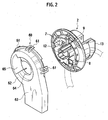
- Fig. 2 is a perspective view of a
female housing 2 and a female housing cover according to the embodiment of the present invention; - Fig. 3 is a perspective view of a grommet according to the embodiment of the present invention;
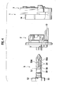
- Fig. 4 is an exploded side view of the lever-fitting type connector according to the embodiment of the present invention;
- Fig. 5 is an exploded side view of the lever-fitting type connector according to the embodiment of the present invention;
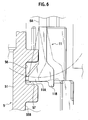
- Fig. 6 is a cross-sectional view of principal parts of the lever-fitting type connector according to the embodiment of the present invention;
- Fig. 7(a) is a front view of an anti-rotation lock of the lever-fitting type connector according to the embodiment of the present invention, and Fig. 7(b) is a cross-sectional view taken along 7b-7b of Fig. 7(a);
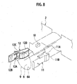
- Fig. 8 is a perspective view of principal parts of the female housing according to the embodiment of the present invention;
- Fig. 9 is a side view of a lever according to the embodiment of the present invention;
- Fig. 10 is a side view of principal parts of the lever according to the embodiment of the present invention;
- Fig. 11 is a cross-sectional view showing a state where the female housing is fully engaged with the lever in the lever-fitting type connector according to the embodiment of the present invention;
- Fig. 12 is a cross-sectional view taken along 12-12 of Fig. 11; and
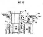
- Fig. 13 is a cross-sectional view of principal parts of the lever-fitting type connector according to the embodiment of the present invention.
- A lever-fitting type connector according to an embodiment of the present invention is explained below in detail.
- The outline of the lever-fitting type connector according to the embodiment of the present invention is as follows. A lever having a rod-like part rotatably inserted into and held by a female housing that serves as a first connector housing is rotated, whereby a male housing serving as a second connector housing is drawn and the both connector housings are fitted into each other. An insertion hole for inserting the lever is provided in the female housing. On an inner wall of this insertion hole, an anti-rotation lock that prevents rotation of the lever when the female and male connector housings are fully engaged (connected) is provided. Further, a rotation-locking concave portion that serves as an abutted member is formed on a circumferential surface of the lever to correspond to this anti-rotation lock.
- On the inner wall of this insertion hole, not only the anti-rotation lock but also a rib that causes the lever to be insertable into the female housing only when the lever is located at a predetermined rotation position and a lever-holding lock having flexibility are provided. This rib is configured to abut on a retaining unit provided on the lever simultaneously with the lever-holding lock, to prevent the lever from coming off, and to hold the lever.
- The lever-fitting type connector according to the present embodiment will be described specifically based on the drawings. As shown in Fig. 1, a lever-
fitting type connector 1 according to the embodiment roughly includes afemale housing 2, amale housing 3, a movingplate 4, and alever 5. Afemale housing cover 60 shown in Fig. 2 is attached onto thefemale housing 2. Further, arubber grommet 70 is attached, as a flexible cover as shown in Fig. 3, onto thefemale housing 2 while thefemale housing cover 60 is attached onto thefemale housing 2. Fig. 5 is a perspective view showing a state where the movingplate 4 is temporarily stopped at themale housing 3, in which view thefemale housing cover 60 and thegrommet 70 are not shown. - As shown in Fig. 1, a
lever insertion hole 6 penetrating thefemale housing 2 in fitting directions A (indicated by an arrow) and serving as an insertion hole is formed generally at center in thefemale housing 2. A plurality ofcavities 7 penetrating thefemale housing 2 along the fitting directions A is formed around thelever insertion hole 6 in thefemale housing 2. A female-terminal metal fitting (not shown) is stored and held in each of thecavities 7. - A through
wiring path 8 which an electric wire (indicated by a chain line in Fig. 2) can be inserted into and arranged in from one of the fitting directions A to the other fitting direction A of thefemale housing 2 without via a fitted portion in which thefemale housing 2 and themale housing 3 are fitted into each other is formed in thefemale housing 2 according to the present embodiment. - As shown in Fig. 2, the
female housing cover 60 for guiding and protecting the electric wire is provided on an end surface of thefemale housing 2 into the side of which surface thelever 5 is inserted. - The
lever insertion hole 6 is a cylindrical hole of acylinder 9 protruding from a generally central portion of thefemale housing 2 on its non-fitted surface side toward a direction opposite to a direction in which thefemale housing 2 is fitted into themale housing 3, and is provided to penetrate a main body of thefemale housing 2. - As shown in Figs. 5 and 8, a
rib 10 protruding into thelever insertion hole 6, a flexible and arm-likelever holding lock 11 facing thislever insertion hole 6, and ananti-rotation lock 12 are provided on aninner wall 6A of thelever insertion hole 6. - The
rib 10, which is a rectangular parallelepiped small protrusion, is configured to be thrust into akey groove 54 formed in thelever 5 and serving as a guide groove, to be described later, when thelever 5 is at a predetermined rotation angle with respect to thefemale housing 2. - As shown in Figs. 5 and 6, the
lever holding lock 11 forms a part of theinner wall 6A of thelever insertion hole 6, and alever holding protrusion 11A protruding into thelever insertion hole 6 is formed on a free end of thelever holding lock 11. Further, alever release protrusion 11B into which a release tool (not shown) is caught protrudes toward themale housing 3 in the fitting directions A in an outside portion of the free end of thelever holding lock 11. - In the present embodiment, as shown in Figs. 5 and 8, the
rib 10 and thelever holding protrusion 11A of thelever holding lock 11 are arranged at positions almost identical in depth in thelever insertion hole 6, the positions of which are deviated from each other by about 90 degrees around a rotation axis. - As shown in Figs. 5, 7(a), and 7(b), the
anti-rotation lock 12 is provided on an end of an inlet of thecylinder 9 of thefemale housing 2. Thisanti-rotation lock 12 has an intermediate portion formed integrally with thecylinder 9, and includes asupport member 12A protruding from the end of the inlet of thecylinder 9 toward the center of theinsertion hole 6, a release-operation plate member 12B rising from an end of thesupport member 12A and exhibiting repellence, trailingarms 12C extending from lower portions of respective both sides of the release-operation plate member 12B toward inward of thelever insertion hole 6, and arotation locking member 12D that are ends of the paired trailingarms 12C and that serves as a generally-rectangular abutment member. Thisrotation locking member 12D is thrust into a rotation-lockingconcave portion 58 of thelever 5, to be described later, thereby preventing over-rotation of thelever 5. - As shown in Fig. 12, each of both
side surfaces 12E in a rotation direction of thelever 5 and aninner side surface 12F opposed to thelever 5 of therotation locking member 12D are set to form an angle smaller than 90 degrees with respect to each other. Due to this, if thelever 5 is over-rotated, then thelever 5 abuts on asidewall surface 58B of the rotation-lockingconcave portion 58, to be described later, and the rotation-lockingmember 12D is urged to be drawn in a direction of thelever 5. Accordingly, it is possible to prevent theanti-rotation lock 12 from being released by over-rotation of thelever 5. - As shown in Fig. 8, the
rotation locking member 12D of theanti-rotation lock 12 is located to be shifted toward a lever inlet side of thelever insertion hole 6 with respect to therib 10 and thelever holding protrusion 11A of thelever holding lock 11 on theinner wall 6A of thelever insertion hole 6. Furthermore, in the present embodiment, theanti-rotation lock 12 is arranged at a position at 180 degrees with respect to thelever holding lock 11, that is, at a position opposed to thelever holding lock 11 around the rotation axis of thelever insertion hole 6. - Moreover, as shown in Fig. 1, a
partition plate 13 that divides the throughwiring path 8 from the fitted portion of thefemale housing 2 is formed on the side of thefemale housing 2 on which side thefemale housing 2 is fitted into themale housing 3. - A configuration of the
female housing cover 60 will be described next with reference to Fig. 2. Thisfemale housing cover 60 is attached onto the non-fitted surface of thefemale housing 2. Thefemale housing cover 60 is configured so that a covermain body 62, which covers up the non-fitted surface of thefemale housing 2 and in which a plurality ofengagement portions 61 to be engaged with a peripheral edge portion of thefemale housing 2 is formed, is formed integrally with awire leading member 63 extending sideways from the covermain body 62. - The cover
main body 62 is generally circular, and acylindrical insertion port 64 into which theabove cylinder 9 of thefemale housing 2 is to be fitted is formed at center of the covermain body 62. Furthermore, anotch space 65 having a generally fan-shaped flat surface is formed from a part of thecylindrical insertion port 64 to outside so as to communicate with thiscylindrical insertion port 64. Thisnotch space 65 is used as a space for operating the release-operation plate member 12B of theanti-rotation lock 12 formed on thecylinder 9 via thegrommet 70 to be described later. - Accordingly, a position at which the
female housing cover 60 is attached onto thefemale housing 2 is set so that the release-operation plate member 12B provided on thecylinder 9 is opposed to thenotch space 65 when thecylinder 9 is inserted into thecylindrical insertion port 64. - Moreover, the
wire leading member 63 bundles and orients a wire connected to the female-terminal metal fittings (not shown) of thefemale housing 2 and the wire arranged to pass through the throughwiring path 8, and functions to protect these wires. - A configuration of the
grommet 70 will be described next with reference to Fig. 3. Thegrommet 70 is a waterproof rubber cover covering up thefemale housing cover 60 and having flexibility, and is configured so that a grommetmain body 71 generally cylindrical container-shaped and covering up the covermain body 62 of thefemale housing cover 60, a leadingmember 72 covering up thewire leading member 63 of thefemale housing cover 60, and a bellows-like bundling cylinder 73 extending from an end of the leadingmember 72, bundling the wires, and having flexibility are formed integrally with one another. - A
lever inlet 74 that communicates with thelever insertion hole 6 and thecylindrical insertion port 64 of thefemale housing cover 2 when thefemale housing 2 is mounted with thefemale housing cover 60 is formed at center of the grommetmain body 71. A release-operationconcave portion 75 is formed at a predetermined position of a side of thislever inlet 74. As shown in Fig. 13, the position of the release-operationconcave portion 75 is set so that the release-operationconcave portion 75 is opposed to the release-operation plate member 12B of theanti-rotation lock 12 provided on the abovefemale housing 2 along an outer side surface of the release-operation plate member 12B. Furthermore, the release-operation plate member 12B forms a space into which a finger can be inserted. - A configuration of the
male housing 3 will be described next with reference to Figs. 1, 4, and 5. Ahood member 14 protruding toward thefemale housing 2 is formed on a fitted surface of a main body of themale housing 3, and thefemale housing 2 is fitted into thishood member 14. Thehood member 14 is shaped to surround a portion of themale housing 3 in which portion thefemale housing 2 is fitted into themale housing 3, and structured so that thepartition plate 13 of thefemale housing 2 is arranged outside of thehood member 14 when the female andmale housings cavities 15 is formed in the main body of themale housing 3 within thehood member 14 along the fitting directions A. A male-terminal metal fitting (not shown) is stored and fixed in each of thesecavities 15, and the male-terminal metal fittings protrude into thehood member 14. - A pair of
lever engagement plates 16, which are opposed to each other and opposed surfaces of which form a part of a circumferential surface of an imaginary cylinder, are provided at a generally central portion of themale housing 3 to protrude into thehood 14. It is to be noted that the opposed surfaces of these pairedlever engagement plates 16 are set to have such dimensions as to slidably contact with an outer circumferential surface of thelever 5. A penetrating hole (not shown) into which thelever 5 is to be fitted is formed between bases of the pairedlever engagement plates 16. Furthermore,engagement protrusions 16A to be captured by and stored inscrew grooves lever 5, to be described later, protrude at positions at which they are opposed each other on the opposed surfaces of the pairedlever engagement plates 16, respectively. - A configuration of the moving
pate 4 will be described with reference to Fig. 1. The movingplate 4 is shaped to be stored in thehood member 14 of themale housing 3, and a plurality of terminal insertion holes 17 into which the respective male-terminal metal fittings (not shown) protruding in thehood member 14 are inserted is formed in the movingplate 4. A generallyrectangular notch 18 into which the pairedlever engagement plates 16 within thehood member 14 of themale housing 3 are inserted is formed in the movingpate 4.Stopper pieces 19 temporarily stopped on themale housing 3 side and engaged with stopper protrusions (not shown) formed at thefemale housing 2 when the female andmale housings notch 18, respectively, to protrude toward thefemale housing 2. Furthermore,stopper pieces 20 are formed to protrude in two portions of a peripheral edge of the movingplate 4, respectively. - A configuration of the
lever 5 will be described next. In the present embodiment, as shown in Figs. 1, 4, 5, and 9, thelever 5 is configured so that a levermain body 51 to be inserted into the female andmale housings units lever 5 on opposite side to a direction in which this levermain body 51 is inserted into thefemale housing 2 for manually performing a rotation operation are formed. The operatingunit 52 is a relatively long rod-like grip member provided at right angle with respect to the levermain body 51, and the operatingunit 53 is provided at a predetermined angle (which is about 70 degrees in this embodiment) with respect to the operatingunit 52 and at right angle with respect to the levermain body 51. - The lever
main body 51 is set to have a length so as to at least penetrate thelever insertion hole 6 of thefemale housing 2 and arrive between the pairedlever engagement plates 16 of themale housing 3 in a state where thefemale housing 2 is not fitted into themale housing 3 and where the bothhousings - A tip end of the lever
main body 51 is formed to be tapered toward the tip end. Because of such a structure tapered toward the tip end, the levermain body 51 can be easily guided to thelever insertion hole 6 of thefemale housing 2 and to between the pairedlever engagement plate 16 of themale housing 3. - Moreover, as shown in Figs. 1, 4, and 5, one
key groove 54 serving as a linear guide groove having a predetermined length from the tip end of the levermain body 51 along axial direction is formed on a circumferential surface of the levermain body 51. Thescrew grooves key groove 54 from the tip end of the levermain body 51 in parallel to start spirally at opposed circumferential surfaces of the tip end portion, respectively. - This
key groove 54 is set to have such a length that both starting points (tip ends) of thescrew grooves engagement protrusions 16A protruding on the opposed surfaces of the respective pairedlever engagement plates 16 of themale housing 3 when a rear end of thekey groove 54 is inserted into positions of therib 10 and thelever holding protrusion 11A of thelever holding lock 11. - Moreover, the rear end of the
key groove 54 is formed to be continuous with alever retaining groove 56 formed circumferentially around the levermain body 51. As shown in Fig. 10, a steppedportion 57A is formed in a predetermined area of a wall member (sidewall surface) 57 of thislever retaining groove 56 located on the tip end side of the levermain body 51. One end of the steppedportion 57A is formed to be continuous with thewall member 57 via atapered surface 57B. The steppedportion 57A has a height difference D from thewall member 57. - Furthermore, as shown in Figs. 1 and 5, a rotation-locking
concave portion 58 in which therotation locking member 12D of theanti-rotation lock 12 is to be stored and serving as an abutted portion is formed in rear of thelever retaining groove 56 of the lever main body 51 (on a rear end side of the lever main body 51). As shown in Fig. 12, this rotation-lockingconcave portion 58 is set to be located at a position so that therotation locking member 12D of theanti-rotation lock 12 is stored in the rotation-lockingconcave portion 58 when thelever 5 is operated to complete connection between thefemale housing 2 and themale housing 3. Further, as shown in Fig. 12, a length of the rotation-lockingconcave portion 58 in a circumferential direction of the levermain body 51 is set to be slightly larger than a width of therotation locking member 12D. Fig. 12 is a cross-sectional view taken along 12-12 of Fig. 11. As shown in Fig. 12, the rotation-lockingconcave portion 58 includes a bottom 58A that is a part of the circumferential surface of thelever 5 and sidewall surfaces 58B provide on both sides of the rotation-lockingconcave portion 58, respectively and rising outward from the bottom at an angle θ smaller than 90 degrees. - A function and an operation of the lever-
fitting type connector 1 according to the present embodiment will be described. - First, as shown in Fig. 1, the moving
plate 4 is temporarily stopped at themale housing 3. At this time, the male-terminal metal fittings (not shown) protruding in thehood member 14 of themale housing 3 are inserted into the corresponding terminal insertion holes 17 formed in the movingplate 4, respectively. As shown in Fig. 11, a wire harness W necessary for through wiring is inserted into the throughwiring path 8 of thefemale housing 2. - Next, connected surfaces of the
female housing 2 and themale housing 3 are abutted against each other and temporarily stopped at each other. The tip end side of thelever 5 is then inserted into thelever insertion hole 6 from thefemale housing 2 side. At this time, thelever 5 is rotated to be placed so that thekey groove 54 formed in the levermain body 51 of thelever 5 can store therein therib 10 protruding into thelever insertion hole 6. By doing so, since thekey groove 54 is the linear groove along the axial direction of the levermain body 51, the levermain body 51 can be inserted into thelever insertion hole 6 while the rib is stored in thekey groove 54. - Thereafter, as the insertion of the lever
main body 51 into thelever insertion hole 6 proceeds, therib 10 abuts on a sidewall of thelever retaining groove 56 and further insertion is thereby prevented. In this manner, simultaneously with movement of therib 10 to the retaininggroove 56, thelever holding protrusion 11A of thelever holding lock 11 overpasses thewall member 57 side and falls down into the retaininggroove 56 due to the repellence as shown in Fig. 6. Forward and backward operations of the levermain body 51 are prevented by thelever holding protrusion 11A, whereby thelever 5 is temporarily stopped at thefemale housing 2. In this state, thelever holding lock 11 is stored in the retaininggroove 56 after being bent outward; therefore, a dimension of thelever holding lock 11 corresponding to an overstroke thereof is present as a clearance between thelever holding lock 11 and thewall member 57. - At this moment, tip ends of the
screw grooves main body 51 are in states where they can cooperatively pick up theengagement protrusions 16A protruding on the opposed surfaces of the pairedlever engagement plates 16. In addition, in this temporarily stopped state, therotation locking member 12D of theanti-rotation lock 12 is stored in aconcave portion 59 circumferentially adjacent to the rotation-lockingconcave portion 58 formed in the levermain body 51. - Next, in the present embodiment, the operating
units lever 5 thus temporarily stopped are rotated counterclockwise, whereby the tip ends of thescrew grooves engagement protrusions 16A of thelever engagement plates 16, and thefemale housing 2 and themale housing 3 are drawn toward each other and fitted into each other. - When rotation of the
lever 5 temporarily stopped at thefemale housing 2 reaches a predetermined rotation angle (about 340 degrees in this embodiment), theengagement protrusions 16A are located on rear ends of thescrew grooves rotation locking member 12D of theanti-rotation lock 12 overpasses the wall member that separates theconcave portion 59 from the rotation-lockingconcave portion 58 and is stored in the rotation-lockingconcave portion 58. At this moment, therotation locking member 12D is engaged with the rotation-lockingconcave portion 58 and the rotation operation (over-rotation) of the levermain body 51 turns into a prevented state (a fully stopped state). Thelever holding protrusion 11A of thelever holding lock 11 makes relative movement along thewall member 57 and abuts on the steppedportion 57A via the taperedsurface 57B to eliminate the clearance, so that it is possible to prevent thelever 5 from becoming shaky in the axial direction. - By preventing the rotation of the
lever 5, the fitting of thefemale housing 2 into themale housing 3 is held without change in the positions of theengagement protrusions 16A relative to thescrew grooves - An operation for releasing connection of the lever-
fitting type connector 1 in the state where thefemale housing 2 is connected to themale housing 3 as stated above will be described next. - As shown in Figs. 7(b) and 13, first, a finger is put into the release-operation
concave portion 75 of thegrommet 70 so as to press the release-operation plate member 12B toward inside of the lever insertion hole 6 (indicated by a thick arrow in Fig. 7B) via the rubber sidewall of the release-operationconcave portion 75. By doing so, therotation locking member 12D stored in the rotation-lockingconcave portion 58 is moved outward (indicated by a thick arrow in Fig. 7B) with thesupport member 12A used as a fulcrum, thus making the levermain body 51 rotatable. - In this state, the operating
units key groove 54 formed in the levermain body 51 is collinear with therib 10. As a result, theengagement protrusions 16A in thescrew grooves screw grooves female housing 2 into themale housing 3 is released. In this state, thelever holding protrusion 11A of thelever holding lock 11 is stored in the retaininggroove 56. Due to this, thelever holding protrusion 11A abuts against thewall member 57 of the retaininggroove 56, so that the levermain body 51 cannot be pulled out from thelever insertion hole 6. - In this state, the
lever release protrusion 11B is bent outward toward a position indicated by a chain line shown in Fig. 6 using a release tool or the like, thereby making it possible to move the levermain body 51 in the axial direction. In this state, the levermain body 51 can be pulled out from thelever insertion hole 6. - The lever-
fitting type connector 1 according to the embodiment of the present invention has be described so far. According to the embodiment, therotation locking member 12D serving as the abutment member of theanti-rotation lock 12 provided on theinner wall 6A of thelever insertion hole 6 of thefemale housing 2 abuts on the rotation-lockingconcave portion 58 serving as the abutted member formed on thelever 5, thereby making it possible to prevent over-rotation of the lever. Further, the abutment surface of therotation locking member 12D and the abutted surface of the rotation-lockingconcave portion 58 are inclined so that therotation locking member 12D is drawn toward the lever at the time of over-rotation. It is, therefore, possible to make it difficult to release theanti-rotation lock 12 and ensure holding the state where the housings are fitted into each other. - Moreover, in the lever-fitting type connector according to the embodiment, the
anti-rotation lock 12 has a so-called seesaw lock structure in which the release-operation plate member 12B and therotation locking member 12D connected to the paired trailingarms 12C are rotated with thesupport member 12A used as the fulcrum. Therefore, by weakly pressing the release-operation plate member 12B from outside via thegrommet 70, it is possible to easily release the lever rotation lock. Accordingly, theanti-rotation lock 12 can be operated from the side of thelever insertion hole 6 of thefemale housing 2, thus improving operability. - With the lever-
fitting type connector 1 according to the embodiment described above, thelever 5 can be inserted into thelever insertion hole 6 only when therib 10 provided on theinner wall 6A of thelever insertion hole 6 formed in thefemale housing 2 meshes with thekey groove 54 formed in thelever 5. It is, therefore, possible to prevent thelever 5 from being inserted into thefemale housing 2 when thelever 5 is located at positions other than the predetermined rotation position and to prevent so-called connection error. - Moreover, according to the present embodiment, the
lever holding lock 11 having flexibility and therib 10 that are provided on theinner wall 6A of thelever insertion hole 6 simultaneously abut on thewall member 57 of the retaininggroove 56 serving as a retaining unit formed in thelever 5, and can prevent thelever 5 from coming off and hold thelever 5. It is, therefore, possible to increase holding force for temporarily stopping (holding) thelever 5 at thefemale housing 2. Further, to release thelever 5, the axial movement of which is restricted by thelever holding lock 11 and therib 10, from thefemale housing 2, it suffices to perform an operation for releasing only a state where thelever holding lock 11 is engaged with thelever 5 while theanti-rotation lock 12 is temporarily released. It is, therefore, possible to improve lever release operability. - Furthermore, according to the present embodiment, the
rib 10 provided on theinner wall 6A of thelever insertion hole 6 is stored in thekey groove 54 of thelever 5, whereby thelever 5 can be inserted into thelever insertion hole 6. It is, therefore, possible to set dimension for close fitting so as not to generate backlash between thelever insertion hole 6 and thelever 5. This can prevent thelever 5 from becoming shaky irrespectively of strength and magnitude of thelever holding lock 11 having flexibility. Accordingly, if themale housing 3 is to be connected to thefemale housing 2 by rotating thelever 5 while thelever 5 is being held at thefemale housing 2, then it is possible to suppress shaking thelever 5 and ensure connecting themale housing 3 to thefemale housing 2 side. - Moreover, according to the present embodiment, the
rib 10 and thelever holding protrusion 11A of thelever holding lock 11 are arranged at the positions deviated from each other in the longitudinal direction of the levermain body 51 by as much as the overstroke of thelever holding lock 11. Due to this, as shown in Fig. 10, a wall surface of a wide portion 56 (the wall member 57) on which therib 10 abuts and a wall surface of anarrow portion 56B (the steppedmember 57A) on which thelever holding protrusion 11A of thelever holding lock 11 abuts while thelever 5 is in the fully stopped state are formed on thelever 5, thereby making it possible to prevent thelever 5 from becoming shaky. Specifically, the wall surface of thewide portion 56A (wall member 57) and that of thenarrow portion 56B (steppedmember 57A) are made continuous on thetapered surface 57B, whereby thefemale housing 2 is fitted into themale housing 3. Accordingly, when thelever 5 is rotated, thelever holding protrusion 11A of thelever holding lock 11 can slide on thetapered surface 57B and the wall surface of thenarrow portion 56B (steppedmember 57A) can smoothly move toward thelever holding protrusion 11A, thereby making it possible to improve operability. - Furthermore, according to the present embodiment, the operating
units lever 5, thereby making it possible to facilitate rotating thelever 5. - The descriptions and drawings that constitute a portion of this disclosure should not be perceived as limiting the present invention. Various alternative embodiments, examples, and operational techniques will become apparent to persons skilled in the art from this disclosure.
- For example, according to the embodiment described above, the lever-
fitting type connector 1 is configured to temporarily stop thelever 5 at thefemale housing 2. Needless to say, thelever 5 can be temporarily stopped at themale housing 3. - Further, in the above embodiment, the instance of simply connecting the
female housing 2 to themale housing 3 has been described. Alternatively, the present invention can be applied to a case where a car interior-side connector housing and an engine room-side connector housing are connected to each other via, for example, an instrument panel of a car between them. In this case, a penetrating hole is formed in the instrument panel, the other housing is temporarily stopped from an opposite side to the instrument panel while holding one housing at the instrument panel, and thelever 5 is rotated from, for example, the car interior side. It is thereby possible to connect the connector housings to each other and facilitate connector attachment operations and release operations. - According to the present invention, it is possible to provide a lever-fitting type connector that can ensure strong connection force between the connector housings and good lock releasing operability.
Claims (7)
- A lever-fitting type connector comprising:a first connector housing;a second connector housing to be fitted into the first connector housing; anda lever rotatably held by the first connector housing, drawing the second connector housing by being rotated to fit the first connector housing and the second connector housing into each other, whereinthe first connector housing includes an insertion hole into which the lever is to be inserted, and an anti-rotation lock that includes an abutment member abutting on an abutted member provided on the lever for preventing over-rotation of the lever is provided on an inner wall of the insertion hole, andan abutment surface of the abutment member in a circumferential direction of the insertion hole and an abutted surface of the abutted member in a circumferential direction of the lever are inclined so that the abutment member is drawn toward the lever when the lever is over-rotated.
- The lever-fitting type connector according to claim 1, wherein the abutted surface is formed on each of both sides of the abutted member in the circumferential direction of the lever.
- The lever-fitting type connector according to claim 1, wherein the abutted member is a rotation-locking concave portion formed on a circumferential surface of the lever.
- The lever-fitting type connector according to claim 1, wherein the anti-rotation lock includes
a support member protruding toward a center of the insertion hole;
a lock releasing unit extending from the support member in an opposite direction to an insertion direction of the lever;
a pair of arm members extending from the lock releasing unit in the insertion direction of the lever, the support member present between the pair of arms; and
the abutment member formed to be connected to tip ends of the pair of arm members. - The lever-fitting connector according to claim 4, wherein the lock releasing unit is exposed to an opposite side of the first connector housing to a direction in which the first connector housing is fitted into the second connector housing.
- The lever-fitting type connector according to claim 5, wherein the first connector housing is covered with a waterproof cover having flexibility, and the lock releasing unit can be operated from an outside of the waterproof cover.
- The lever-fitting type connector according to claim 6, wherein a release-operation concave portion that enables operating the lock releasing unit is formed in the waterproof cover.
Applications Claiming Priority (2)
| Application Number | Priority Date | Filing Date | Title |
|---|---|---|---|
| JP2004259748A JP4335103B2 (en) | 2004-09-07 | 2004-09-07 | Lever fitting type connector |
| PCT/JP2005/016302 WO2006028075A1 (en) | 2004-09-07 | 2005-09-06 | Lever-fit connector |
Publications (3)
| Publication Number | Publication Date |
|---|---|
| EP1804342A1 true EP1804342A1 (en) | 2007-07-04 |
| EP1804342A4 EP1804342A4 (en) | 2011-01-26 |
| EP1804342B1 EP1804342B1 (en) | 2012-07-11 |
Family
ID=36036356
Family Applications (1)
| Application Number | Title | Priority Date | Filing Date |
|---|---|---|---|
| EP05781938A Ceased EP1804342B1 (en) | 2004-09-07 | 2005-09-06 | Lever-fit connector |
Country Status (4)
| Country | Link |
|---|---|
| US (1) | US7448887B2 (en) |
| EP (1) | EP1804342B1 (en) |
| JP (1) | JP4335103B2 (en) |
| WO (1) | WO2006028075A1 (en) |
Families Citing this family (8)
| Publication number | Priority date | Publication date | Assignee | Title |
|---|---|---|---|---|
| JP5578927B2 (en) * | 2010-01-12 | 2014-08-27 | 矢崎総業株式会社 | Low insertion force connector |
| JP5711569B2 (en) * | 2011-03-01 | 2015-05-07 | 矢崎総業株式会社 | Connector fitting jig and low insertion force connector |
| JP6200321B2 (en) * | 2013-12-26 | 2017-09-20 | 矢崎総業株式会社 | connector |
| DE102016014096A1 (en) * | 2016-06-17 | 2017-12-21 | Gentherm Gmbh | Device for producing an electrically conductive connection |
| JP6944385B2 (en) * | 2018-01-11 | 2021-10-06 | フクシマガリレイ株式会社 | Wiring connector |
| JP6785265B2 (en) * | 2018-06-15 | 2020-11-18 | 矢崎総業株式会社 | Terminal |
| JP7271498B2 (en) * | 2020-12-16 | 2023-05-11 | 矢崎総業株式会社 | equipment connector |
| JP7376522B2 (en) * | 2021-03-02 | 2023-11-08 | 矢崎総業株式会社 | How to manufacture connectors |
Family Cites Families (16)
| Publication number | Priority date | Publication date | Assignee | Title |
|---|---|---|---|---|
| US4454398A (en) * | 1981-03-16 | 1984-06-12 | Eaton Corporation | Terminal seal for miniature sealed toggle switch |
| JPH0613069U (en) * | 1992-03-12 | 1994-02-18 | 日本航空電子工業株式会社 | connector |
| JPH0613069A (en) | 1992-06-26 | 1994-01-21 | Ricoh Co Ltd | Battery pack device |
| JP2613998B2 (en) | 1992-07-10 | 1997-05-28 | 矢崎総業株式会社 | Mating structure of low insertion force connector |
| JPH0729765A (en) | 1993-07-08 | 1995-01-31 | Matsushita Electric Ind Co Ltd | Large capacity capacitor |
| JP2697562B2 (en) | 1993-07-30 | 1998-01-14 | 松下電器産業株式会社 | Garbage processing machine |
| JP2605489Y2 (en) * | 1993-09-17 | 2000-07-17 | タイコエレクトロニクスアンプ株式会社 | Electrical connector mating release mechanism |
| JP3285303B2 (en) | 1995-11-02 | 2002-05-27 | 矢崎総業株式会社 | Half mating prevention connector |
| JPH1167325A (en) | 1997-08-20 | 1999-03-09 | Meikosha:Kk | Connector |
| US6120313A (en) * | 1999-01-15 | 2000-09-19 | Delphi Technologies, Inc. | Connector bodies with high force positioning mechanism |
| JP3600223B2 (en) * | 2002-06-27 | 2004-12-15 | 株式会社アイティティキャノン | Multi-core connector |
| US6929619B2 (en) * | 2002-08-02 | 2005-08-16 | Liebel-Flarshiem Company | Injector |
| US6811417B2 (en) * | 2003-02-18 | 2004-11-02 | Calsonic Kansei Corporation | Connector structure |
| US7108523B2 (en) * | 2004-04-07 | 2006-09-19 | Finisar Corporation | Pluggable transceiver with cover resilient member |
| JP4335102B2 (en) * | 2004-09-03 | 2009-09-30 | 矢崎総業株式会社 | Lever fitting type connector |
| JP2007179860A (en) * | 2005-12-27 | 2007-07-12 | Jst Mfg Co Ltd | connector |
-
2004
- 2004-09-07 JP JP2004259748A patent/JP4335103B2/en not_active Expired - Lifetime
-
2005
- 2005-09-06 US US11/661,933 patent/US7448887B2/en not_active Expired - Fee Related
- 2005-09-06 EP EP05781938A patent/EP1804342B1/en not_active Ceased
- 2005-09-06 WO PCT/JP2005/016302 patent/WO2006028075A1/en not_active Ceased
Also Published As
| Publication number | Publication date |
|---|---|
| US7448887B2 (en) | 2008-11-11 |
| US20080194129A1 (en) | 2008-08-14 |
| JP4335103B2 (en) | 2009-09-30 |
| EP1804342A4 (en) | 2011-01-26 |
| JP2006079844A (en) | 2006-03-23 |
| EP1804342B1 (en) | 2012-07-11 |
| WO2006028075A1 (en) | 2006-03-16 |
Similar Documents
| Publication | Publication Date | Title |
|---|---|---|
| US7347732B2 (en) | Connector | |
| JP3252955B2 (en) | Lever connector | |
| US7347710B2 (en) | Electric wire connector having a lock securing mechanism | |
| US7255581B2 (en) | Lever-type connector | |
| JP6249998B2 (en) | connector | |
| US20070184692A1 (en) | Connector structure | |
| US6935887B2 (en) | Connector preventive of incomplete fitting | |
| EP3764481B1 (en) | Lever-type connector | |
| US7448887B2 (en) | Lever-fitting type connector | |
| US7749016B2 (en) | Lever-fitting type connector with rotatably insertable locking lever | |
| US5672068A (en) | Lever-joint type connecting structure | |
| JP2000067982A (en) | Connector housing and connector using the same | |
| US7976332B2 (en) | LIF connector | |
| US11482811B2 (en) | Lever-type connector | |
| CN116941143A (en) | Rod type connector | |
| US6191364B1 (en) | Clamping construction for an automotive wiring harness | |
| CN119354253A (en) | Rod housing | |
| JP3893298B2 (en) | Protector | |
| US20210249815A1 (en) | Lever type connector | |
| JPH11176517A (en) | Combined connector and joined structure of combined connector and casing | |
| JP4158686B2 (en) | Lock structure | |
| US20250141146A1 (en) | Electrical connector assembly and method for assembling same | |
| CN119362079A (en) | Connector structure | |
| JP2006100167A (en) | Housing for electrical connector | |
| JP2001185869A (en) | Electrical junction box |
Legal Events
| Date | Code | Title | Description |
|---|---|---|---|
| PUAI | Public reference made under article 153(3) epc to a published international application that has entered the european phase |
Free format text: ORIGINAL CODE: 0009012 |
|
| 17P | Request for examination filed |
Effective date: 20070404 |
|
| AK | Designated contracting states |
Kind code of ref document: A1 Designated state(s): DE FR |
|
| DAX | Request for extension of the european patent (deleted) | ||
| RBV | Designated contracting states (corrected) |
Designated state(s): DE FR |
|
| A4 | Supplementary search report drawn up and despatched |
Effective date: 20101227 |
|
| RIC1 | Information provided on ipc code assigned before grant |
Ipc: H01R 13/631 20060101ALI20101220BHEP Ipc: H01R 13/621 20060101AFI20101220BHEP Ipc: H01R 13/639 20060101ALI20101220BHEP Ipc: H01R 13/629 20060101ALI20101220BHEP |
|
| 17Q | First examination report despatched |
Effective date: 20110919 |
|
| GRAP | Despatch of communication of intention to grant a patent |
Free format text: ORIGINAL CODE: EPIDOSNIGR1 |
|
| GRAS | Grant fee paid |
Free format text: ORIGINAL CODE: EPIDOSNIGR3 |
|
| GRAA | (expected) grant |
Free format text: ORIGINAL CODE: 0009210 |
|
| AK | Designated contracting states |
Kind code of ref document: B1 Designated state(s): DE FR |
|
| REG | Reference to a national code |
Ref country code: DE Ref legal event code: R096 Ref document number: 602005035150 Country of ref document: DE Effective date: 20120906 |
|
| PLBE | No opposition filed within time limit |
Free format text: ORIGINAL CODE: 0009261 |
|
| STAA | Information on the status of an ep patent application or granted ep patent |
Free format text: STATUS: NO OPPOSITION FILED WITHIN TIME LIMIT |
|
| 26N | No opposition filed |
Effective date: 20130412 |
|
| REG | Reference to a national code |
Ref country code: DE Ref legal event code: R097 Ref document number: 602005035150 Country of ref document: DE Effective date: 20130412 |
|
| REG | Reference to a national code |
Ref country code: FR Ref legal event code: PLFP Year of fee payment: 12 |
|
| REG | Reference to a national code |
Ref country code: FR Ref legal event code: PLFP Year of fee payment: 13 |
|
| PGFP | Annual fee paid to national office [announced via postgrant information from national office to epo] |
Ref country code: DE Payment date: 20170830 Year of fee payment: 13 Ref country code: FR Payment date: 20170810 Year of fee payment: 13 |
|
| REG | Reference to a national code |
Ref country code: DE Ref legal event code: R119 Ref document number: 602005035150 Country of ref document: DE |
|
| PG25 | Lapsed in a contracting state [announced via postgrant information from national office to epo] |
Ref country code: DE Free format text: LAPSE BECAUSE OF NON-PAYMENT OF DUE FEES Effective date: 20190402 |
|
| PG25 | Lapsed in a contracting state [announced via postgrant information from national office to epo] |
Ref country code: FR Free format text: LAPSE BECAUSE OF NON-PAYMENT OF DUE FEES Effective date: 20180930 |