EP1804326A1 - Monocrystalline silicon flow connector and microfluidic system modularly built thereon for feeding a fuel solution to direct methanol fuel cell - Google Patents
Monocrystalline silicon flow connector and microfluidic system modularly built thereon for feeding a fuel solution to direct methanol fuel cell Download PDFInfo
- Publication number
- EP1804326A1 EP1804326A1 EP06425001A EP06425001A EP1804326A1 EP 1804326 A1 EP1804326 A1 EP 1804326A1 EP 06425001 A EP06425001 A EP 06425001A EP 06425001 A EP06425001 A EP 06425001A EP 1804326 A1 EP1804326 A1 EP 1804326A1
- Authority
- EP
- European Patent Office
- Prior art keywords
- coinciding
- channel
- solution
- flow connector
- silicon
- Prior art date
- Legal status (The legal status is an assumption and is not a legal conclusion. Google has not performed a legal analysis and makes no representation as to the accuracy of the status listed.)
- Withdrawn
Links
- 229910021421 monocrystalline silicon Inorganic materials 0.000 title claims abstract description 23
- OKKJLVBELUTLKV-UHFFFAOYSA-N Methanol Chemical compound OC OKKJLVBELUTLKV-UHFFFAOYSA-N 0.000 title claims description 71
- 239000000446 fuel Substances 0.000 title claims description 44
- XUIMIQQOPSSXEZ-UHFFFAOYSA-N Silicon Chemical compound [Si] XUIMIQQOPSSXEZ-UHFFFAOYSA-N 0.000 claims abstract description 58
- 229910052710 silicon Inorganic materials 0.000 claims abstract description 58
- 239000010703 silicon Substances 0.000 claims abstract description 58
- 230000008878 coupling Effects 0.000 claims abstract description 20
- 238000010168 coupling process Methods 0.000 claims abstract description 20
- 238000005859 coupling reaction Methods 0.000 claims abstract description 20
- 239000002699 waste material Substances 0.000 claims abstract description 14
- 150000001875 compounds Chemical class 0.000 claims abstract description 8
- 230000000740 bleeding effect Effects 0.000 claims abstract description 5
- 239000002904 solvent Substances 0.000 claims abstract description 4
- 239000000243 solution Substances 0.000 claims description 58
- 238000006243 chemical reaction Methods 0.000 claims description 12
- 238000011084 recovery Methods 0.000 claims description 6
- 239000007864 aqueous solution Substances 0.000 claims description 4
- 239000012527 feed solution Substances 0.000 claims description 3
- LFQSCWFLJHTTHZ-UHFFFAOYSA-N Ethanol Chemical compound CCO LFQSCWFLJHTTHZ-UHFFFAOYSA-N 0.000 claims 4
- 238000004519 manufacturing process Methods 0.000 abstract description 2
- XLYOFNOQVPJJNP-UHFFFAOYSA-N water Substances O XLYOFNOQVPJJNP-UHFFFAOYSA-N 0.000 description 15
- 239000013078 crystal Substances 0.000 description 5
- 238000010586 diagram Methods 0.000 description 5
- 239000000853 adhesive Substances 0.000 description 4
- 230000001070 adhesive effect Effects 0.000 description 4
- 239000003153 chemical reaction reagent Substances 0.000 description 4
- 239000012530 fluid Substances 0.000 description 4
- 239000007788 liquid Substances 0.000 description 4
- 239000012528 membrane Substances 0.000 description 4
- 238000000034 method Methods 0.000 description 4
- CURLTUGMZLYLDI-UHFFFAOYSA-N Carbon dioxide Chemical compound O=C=O CURLTUGMZLYLDI-UHFFFAOYSA-N 0.000 description 3
- 230000000694 effects Effects 0.000 description 3
- 238000005530 etching Methods 0.000 description 3
- 230000005484 gravity Effects 0.000 description 3
- 239000001257 hydrogen Substances 0.000 description 3
- 229910052739 hydrogen Inorganic materials 0.000 description 3
- 230000010287 polarization Effects 0.000 description 3
- 238000012546 transfer Methods 0.000 description 3
- UFHFLCQGNIYNRP-UHFFFAOYSA-N Hydrogen Chemical compound [H][H] UFHFLCQGNIYNRP-UHFFFAOYSA-N 0.000 description 2
- 229910002092 carbon dioxide Inorganic materials 0.000 description 2
- 230000007423 decrease Effects 0.000 description 2
- 238000013461 design Methods 0.000 description 2
- 239000003792 electrolyte Substances 0.000 description 2
- 238000005516 engineering process Methods 0.000 description 2
- 238000005459 micromachining Methods 0.000 description 2
- 238000012545 processing Methods 0.000 description 2
- 239000007787 solid Substances 0.000 description 2
- VYPSYNLAJGMNEJ-UHFFFAOYSA-N Silicium dioxide Chemical compound O=[Si]=O VYPSYNLAJGMNEJ-UHFFFAOYSA-N 0.000 description 1
- 230000003213 activating effect Effects 0.000 description 1
- 238000013459 approach Methods 0.000 description 1
- QVGXLLKOCUKJST-UHFFFAOYSA-N atomic oxygen Chemical compound [O] QVGXLLKOCUKJST-UHFFFAOYSA-N 0.000 description 1
- 230000015572 biosynthetic process Effects 0.000 description 1
- 239000001569 carbon dioxide Substances 0.000 description 1
- 238000002485 combustion reaction Methods 0.000 description 1
- 238000004891 communication Methods 0.000 description 1
- 238000000151 deposition Methods 0.000 description 1
- 238000011161 development Methods 0.000 description 1
- 238000007599 discharging Methods 0.000 description 1
- 239000003822 epoxy resin Substances 0.000 description 1
- 239000007789 gas Substances 0.000 description 1
- 231100001261 hazardous Toxicity 0.000 description 1
- XLYOFNOQVPJJNP-ZSJDYOACSA-N heavy water Substances [2H]O[2H] XLYOFNOQVPJJNP-ZSJDYOACSA-N 0.000 description 1
- -1 hydrogen ions Chemical class 0.000 description 1
- 238000005304 joining Methods 0.000 description 1
- 230000014759 maintenance of location Effects 0.000 description 1
- 239000000463 material Substances 0.000 description 1
- 230000007246 mechanism Effects 0.000 description 1
- 238000001465 metallisation Methods 0.000 description 1
- VUZPPFZMUPKLLV-UHFFFAOYSA-N methane;hydrate Chemical compound C.O VUZPPFZMUPKLLV-UHFFFAOYSA-N 0.000 description 1
- 230000003647 oxidation Effects 0.000 description 1
- 238000007254 oxidation reaction Methods 0.000 description 1
- 239000001301 oxygen Substances 0.000 description 1
- 229910052760 oxygen Inorganic materials 0.000 description 1
- 238000000059 patterning Methods 0.000 description 1
- 229920000647 polyepoxide Polymers 0.000 description 1
- 229920001296 polysiloxane Polymers 0.000 description 1
- 230000001681 protective effect Effects 0.000 description 1
- 238000012827 research and development Methods 0.000 description 1
- 230000000979 retarding effect Effects 0.000 description 1
- 238000007789 sealing Methods 0.000 description 1
- 239000012945 sealing adhesive Substances 0.000 description 1
- 229910052814 silicon oxide Inorganic materials 0.000 description 1
- 239000000126 substance Substances 0.000 description 1
- 230000000930 thermomechanical effect Effects 0.000 description 1
Images




Classifications
-
- H—ELECTRICITY
- H01—ELECTRIC ELEMENTS
- H01M—PROCESSES OR MEANS, e.g. BATTERIES, FOR THE DIRECT CONVERSION OF CHEMICAL ENERGY INTO ELECTRICAL ENERGY
- H01M8/00—Fuel cells; Manufacture thereof
- H01M8/24—Grouping of fuel cells, e.g. stacking of fuel cells
- H01M8/2465—Details of groupings of fuel cells
- H01M8/2484—Details of groupings of fuel cells characterised by external manifolds
-
- H—ELECTRICITY
- H01—ELECTRIC ELEMENTS
- H01M—PROCESSES OR MEANS, e.g. BATTERIES, FOR THE DIRECT CONVERSION OF CHEMICAL ENERGY INTO ELECTRICAL ENERGY
- H01M8/00—Fuel cells; Manufacture thereof
- H01M8/10—Fuel cells with solid electrolytes
- H01M8/1009—Fuel cells with solid electrolytes with one of the reactants being liquid, solid or liquid-charged
- H01M8/1011—Direct alcohol fuel cells [DAFC], e.g. direct methanol fuel cells [DMFC]
-
- H—ELECTRICITY
- H01—ELECTRIC ELEMENTS
- H01M—PROCESSES OR MEANS, e.g. BATTERIES, FOR THE DIRECT CONVERSION OF CHEMICAL ENERGY INTO ELECTRICAL ENERGY
- H01M8/00—Fuel cells; Manufacture thereof
- H01M8/10—Fuel cells with solid electrolytes
- H01M2008/1095—Fuel cells with polymeric electrolytes
-
- H—ELECTRICITY
- H01—ELECTRIC ELEMENTS
- H01M—PROCESSES OR MEANS, e.g. BATTERIES, FOR THE DIRECT CONVERSION OF CHEMICAL ENERGY INTO ELECTRICAL ENERGY
- H01M2250/00—Fuel cells for particular applications; Specific features of fuel cell system
- H01M2250/30—Fuel cells in portable systems, e.g. mobile phone, laptop
-
- Y—GENERAL TAGGING OF NEW TECHNOLOGICAL DEVELOPMENTS; GENERAL TAGGING OF CROSS-SECTIONAL TECHNOLOGIES SPANNING OVER SEVERAL SECTIONS OF THE IPC; TECHNICAL SUBJECTS COVERED BY FORMER USPC CROSS-REFERENCE ART COLLECTIONS [XRACs] AND DIGESTS
- Y02—TECHNOLOGIES OR APPLICATIONS FOR MITIGATION OR ADAPTATION AGAINST CLIMATE CHANGE
- Y02B—CLIMATE CHANGE MITIGATION TECHNOLOGIES RELATED TO BUILDINGS, e.g. HOUSING, HOUSE APPLIANCES OR RELATED END-USER APPLICATIONS
- Y02B90/00—Enabling technologies or technologies with a potential or indirect contribution to GHG emissions mitigation
- Y02B90/10—Applications of fuel cells in buildings
-
- Y—GENERAL TAGGING OF NEW TECHNOLOGICAL DEVELOPMENTS; GENERAL TAGGING OF CROSS-SECTIONAL TECHNOLOGIES SPANNING OVER SEVERAL SECTIONS OF THE IPC; TECHNICAL SUBJECTS COVERED BY FORMER USPC CROSS-REFERENCE ART COLLECTIONS [XRACs] AND DIGESTS
- Y02—TECHNOLOGIES OR APPLICATIONS FOR MITIGATION OR ADAPTATION AGAINST CLIMATE CHANGE
- Y02E—REDUCTION OF GREENHOUSE GAS [GHG] EMISSIONS, RELATED TO ENERGY GENERATION, TRANSMISSION OR DISTRIBUTION
- Y02E60/00—Enabling technologies; Technologies with a potential or indirect contribution to GHG emissions mitigation
- Y02E60/30—Hydrogen technology
- Y02E60/50—Fuel cells
-
- Y—GENERAL TAGGING OF NEW TECHNOLOGICAL DEVELOPMENTS; GENERAL TAGGING OF CROSS-SECTIONAL TECHNOLOGIES SPANNING OVER SEVERAL SECTIONS OF THE IPC; TECHNICAL SUBJECTS COVERED BY FORMER USPC CROSS-REFERENCE ART COLLECTIONS [XRACs] AND DIGESTS
- Y02—TECHNOLOGIES OR APPLICATIONS FOR MITIGATION OR ADAPTATION AGAINST CLIMATE CHANGE
- Y02P—CLIMATE CHANGE MITIGATION TECHNOLOGIES IN THE PRODUCTION OR PROCESSING OF GOODS
- Y02P70/00—Climate change mitigation technologies in the production process for final industrial or consumer products
- Y02P70/50—Manufacturing or production processes characterised by the final manufactured product
Definitions
- the present invention relates to energy converting devices in the form of a single or a plurality of electrochemical cells, to at least an electrode of which a solution containing an oxidable compound is fed.
- the invention relates to fuel cells or to stacks composed of a plurality of cells, the intercell and terminal conductive bodies of which are of micromachined monocrystalline silicon.
- PEMFC Polymeric electrolyte membrane fuel cells
- a reagent like hydrogen is fed in gaseous form to the active electrode
- a reagent is fed in solution to the electrode of an electrochemical cell, be it the anode of a fuel cell or of a redox flow cell or any other electrochemical cell
- the kinetic of mass transfer of the reacting species to the active reaction sites, of the electrode becomes a major factor of overall polarization effects, in consideration of the diffusive mechanisms across the interface between the solid electrode and the solution and within the bulk of the solution, essentially governed by concentration gradients.
- a forced circulation of the solution of the reagent through the electrode compartment reduces polarization effects by equalizing concentration gradients in the bulk of the solution and preventing excessive localized depletion of the reagent species over the whole active area of the cell (electrode).
- micro-machining technologies of monocrystalline silicon that has permitted to realize microelectro-mechanical devices and sensors on silicon (MEMS) and the same technologies have also found application in the fabrication of electrochemical cells of micro to small size (up to wafer-size cells).
- the present applicants have found an effective solution to these difficulties and inconveniences based on the provision of a flow connector in the form of a micromachined monocrystalline silicon plate or platform, on a side of which all the functional components of the microfluidic feed system are fixed and connected in a leak proof manner.
- the monocrystalline silicon platform has a channeled bottom side that is finally coupled onto a flat surface of a terminal silicon body of the energy conversion device to which the solution must be fed.
- the coupling of the channelled silicon platform constituting the flow connector onto a receiving flat surface of the terminal silicon body of the device to be fed with the solution can be realized by any suitable known technique for permanently joining together in a leak proof manner two distinct monocrystalline silicon bodies.
- the coupling is made by a wafer bonding technique optionally employing an adhesive.
- the microfluidic solution feed system is realized on top of the silicon platform constituting the flow connector element by fixing over the top surface of the silicon platform prefabricated functional components of the microfluidic system.
- the system includes at least a silicon micropump module having an inlet or suction port and an outlet or delivery port coinciding with respective holes through the silicon platform constituting the flow connector, that open in distinct channels, a suction channel and a delivery channel, respectively, defined in the bottom side of the silicon platform.
- the system includes a plurality of silicon micro valve modules fixed onto the silicon platform in correspondence of holes through the silicon platform that functionally open either into the channel leading to the suction port hole of the pump or into the channel into which the delivery port hole of the pump opens.
- Distinct solvent (water) and a soluble oxidable compound or fuel (methanol) cartridges are fastened onto the silicon platform, each having an outlet aperture coincident with the inlet port of a respective release microvalve module.
- a depleted solution waste recovery cartridge is also mounted on the silicon platform and has an inlet aperture coincident with the outlet port of a third discharge microvalve module, the inlet port of which coincides with a hole reaching the delivery channel of the micropump.
- the silicon microvalves are of the NC type (normally-closed) and are preferably of thermomechanical type, to be opened by forcing an electric current through a thermoelectric actuator for opening the inner flow orifice of the valve.
- the silicon micropump is preferably of the piezoelectric type, though it may alternatively be of any other commonly known types of silicon micropumps, for example of bimetallic, electrostatic or thermopneumatic type.
- each functional component module onto the monocrystalline silicon platform, ensuring the necessary leak proof coupling of the respective flow apertures or ports of the components modules to the respective ports or holes through the silicon platform, and upon bonding the channeled bottom side of the monocrystalline silicon platform constituting the flow connector of the system onto a receiving flat surface of a monocrystalline silicon terminal body of the energy converting device, having at least an inlet port and an outlet port of the solution, the whole assembly assumes an outstandingly compact and solid constitution, practically overcoming any criticalness relating to mechanical sturdiness of the assembly and of necessary leak proof hydraulic couplings among the component parts that define the microfluidic system flow paths.
- an appropriate adhesive for example with an epoxy resin adhesive or with a different sealing adhesive
- the illustrative embodiment depicted in the figures relates to an important application of a silicon flow connector based microfluidic feed system of this invention to a silicon fuel cell stack, through the anode compartments of which is circulated an aqueous solution of methanol, the molarity of which may be generally controlled to be in a range from 0.5 M to 2 M or even higher.
- the cell area size may be in the order of 20 to 100 cm 2 , appropriate for realizing a portable power source for recharging batteries of electronic instruments PCs, GPS systems, communications devices and alike.
- the presence of three distinct reservoirs or cartridges is contemplated.
- a first cartridge C1 contains a certain volume of demineralized water
- a second cartridge C2 contains a certain volume of methanol
- in a third cartridge C3, depleted solution may be periodically drained for replenishing the system with fresh fuel solution (refresh operation).
- the supply cartridges C1 and C2, of H 2 O and CH 3 OH, respectively, have their discharge orifice controlled by respective release microvalves V1 and V2 and so is the inlet orifice of the waste solution cartridge C3 by a dedicated third drainage microvalve V3.
- the flow connector 1 defines at least a suction channel and a delivery channel that respectively connect the suction and delivery ports of a piezoelectric micropump P to an inlet manifold and to an outlet manifold of the fuel solution to and from the fuel cell stack FC.
- the three microvalves V1, V2 and V3 and the piezoelectric micropump P are programmably driven by an electronic control unit CU.
- thermoelectric actuator The opening of the normally closed microvalves V1, V2, V3 is commanded by circulating a current I through a thermoelectric actuator.
- the piezoelectric micropump P is driven by controlling the voltage and/or frequency applied to piezoelectric crystal fastened to a pump membrane that transmit vibrations to liquid contained in a pump chamber, having monodirectional suction valve and a monodirectional delivery valve.
- Figure 2 is represented the resultant flow circuit of the system during a preliminary phase of filling the microfluidic fuel feed circuit with a solution of methanol in water, by gravity.
- the micropump P is not driven, while the release microvalves V1 and V2 that control the release of the content of the water cartridge C 1 and of the methanol cartridge C2, are opened for precisely predetermined intervals of time in order to fill the system with a solution of methanol of the desired molarity (concentration).
- An operating phase of energy conversion of chemical energy into electrical energy with circulation of an electric current in an external load circuit of the battery is conducted by activating the micropump P, by the application of a controlled AC voltage to the piezoelectric crystal mechanically fastened to a membrane that transfers the vibration induced by the piezoelectric crystal to the fluid contained in the pump chamber connected to the inlet and output ports through monodirectional microvalves.
- the valve stopper may be a cantilever arm, normally abutting over the valve flow orifice.
- Figure 3 is a representation of the resultant flow circuit of the fuel feed system during a phase of energy conversion taking place in the microfuel cell stack FC.
- the energy conversion process occurring in the fuel cell FC through a direct methanol oxidation to carbon dioxide and water is supported by the circulation of electric current in the load circuit connected to the terminal cathode (+) and to the terminal anode (-) of the fuel cell or multiple fuel cell stack.
- the attendant decline of the cell voltage can be countered to some extent by increasing progressively the rate of circulation of the solution by increasing the drive voltage and/or changing the frequency that is applied to the piezoelectric crystal of the micropump.
- this phase of refreshing the fuel solution that is circulated through the fuel cell(s) anode compartment(s) is implemented by commanding a resultant configuration of the fluid circuit as depicted in Figure 4.
- the bleed microvalve V3 of depleted solution from the fuel cell circuit into the waste solution cartridge C3 is commanded open while continuing to pump the solution in circulation, and the methanol release microvalve (and successively and independently also the water release microvalve, if necessary) is also opened. Therefore, a bleeding of the solution into the waste solution cartridge C3 takes place, the bled volume of which is replenished with methanol drawn into the fuel cell circuit from the supply cartridge C2, until the cell voltage rises back according to the expected value, optionally opening also the water supply microvalve V 1 for computed intervals of time.
- This refresh operation is driven by a pressure difference that exists between suction and delivery channels to the micropump, and by a positive difference of free liquid levels between the supply cartridges C1 and C2 (initially full) and the waste solution recovery cartridge C3 (initially empty).
- the bleed microvalve V3 for discharging solution into the waste solution cartridge C3 is closed by interrupting any further electric current drive to it and thereafter also the methanol and/or eventually water supply microvalves V2 and V1 are closed to return the system to the normal operating configuration of Figure 3.
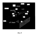
- Figure 5 depicts how the silicon flow connector 1 carrying the functional components of the microfluidic feed system fixed onto the silicon platform 1 is finally coupled onto the flat silicon surface of the end of a multicell, stack.
- an inlet manifold 2 through which the fuel feed solution is distributed to the anodes of the multiple cell stack and an outlet manifold 3 from which the solution circulated by the main pump in the monofluidic fuel feed circuit returns to the pump, as graphically indicated by the dash line arrows.
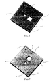
- micromachined monocrystalline silicon platform 1 constituting the flow connector is illustrated in Figures 6 and 7, respectively, a three-dimensional view from atop and a three-dimensional view from below.
- the thickness of the monocrystalline silicon platform 1 may generally be comprised between 0.2 mm and 0.5 mm or exceptionally even larger.
- two distinct channels or extended recesses 5 and 6 of depth substantially uniform are formed in the bottom side of the monocrystalline silicon platform 1.
- the depth of the channels 5 and 6 is preferably comprised between 10% and 30% of the full thickness of the monocrystalline silicon platform 1.
- the through hole 7 coincides with the outlet port of the silicon microvalve module V1 fixed onto the platform, the inlet port of which couples with a discharge orifice of the water supply cartridge C1.
- the through hole 8 coincides with the outlet port of the silicon microvalve module V2 fixed onto the platform, the inlet port of which couples to a discharge orifice of the water to the outlet of the water supply cartridge C1.
- the through hole 9 at the inner end of the suction channel 5 coincides with the suction port of the silicon micropump module p fixed onto the platform, the delivery port of which coincides with the through hole 10 reaching the delivery channel 6.
- the through hole 11 coincides with the inlet port of the silicon microvalve module V3 fixed onto the platform, the outlet port of which couples with the inlet orifice of the waste solution cartridge C1.
- the channels 5 and 6 and the through holes 7, 8, 9, 10 and 11, can be formed by anisotropic etching of the monocrystalline silicon using as etchant KOH, according to a well known silicon micromachining practice.
- the through holes and the channels 5 and 6 may be formed through a unified etching step by differentiating as needed the etching depth between the microchannels 5 and 6 and the through holes 7-11 by depositing and patterning layers of etch retarding material commonly of silicon oxide.
- protective and/or of retardant layers can normally be carried out in appropriate ovens, while the definition of the etch areas can be done by common photolithographic techniques.
- Figures 8a and 8b are three-dimensional views of a piezoelectric silicon micropump.
- Figure 9a and Figure 9b are three-dimensional views of the two release and bleed silicon microvalves V1, V2 and V3 associated to the water supply cartridge C1 and to the methanol supply cartridge supply C2, respectively and to the waste solution recovery cartridge C3.
- the silicon microvalves may preferably be of the thermoelectric type including a thermoelectrically driven stopper.
- the heat input by Joule effect to open the valve stopper is provided by forcing a current through resistive elements (indicated in Figure 9a by the metallization pattern 15 that define) pads for electrically connecting the valve to the control circuit.
- the port 7b (8b) visible in the bottom side view of the microvalve module of Figure 9b, is aligned with the respective through hole 7 or 8 or 11 of the silicon flow connector 1, while the other port of the valve 16 present on the top side, visible in Figure 9a, couples with the release or inlet orifice of the respective cartridge.
- Figure 10b is shown the bottom side of a cartridge reservoir from which is observable the aperture 16c present in a stepped portion of the bottom of the cartridge overlapping a portion of the associated microvalve module such to couple with the upper side port 16 of the silicon microvalve module for controlling either the release of fluid from the cartridge or the bleeding of depleted solution into the cartridge.
- the supply cartridges C1 and C2 and the waste solution cartridge C3 are coupled to the respective valve modules V1, V2 and V3 and held fast onto the silicon platform 1 not in a permanent manner but preferably in a manner that will permit an easy and quick replacement of the cartridges with new ones.
- each cartridge may be alignedly fixed on the silicon platform using a soft sigillant adhesive, for example silicone, or according to an alternative embodiment, each cartridge may include an interconnect element that may be permanently fixed in a leak proof manner onto the respective microvalve module and on the immediately adjacent surface of the silicon platform.
- the interconnect element or sub-module will have a male or female part of a snap-action coupling suitable to receive and retain a cartridge provided with a coordinately installed female or male part of the snap-action coupling.
- the coupling besides hydraulically connecting the reservoir to the microfluidic fuel feed system will also provide an adequate mechanical retention of the replaceable cartridge onto the interconnect element, permanently fixed onto the silicon platform.
- the coupling part fitted at the bottom of the removable cartridge may include a removable or breakable seal that is removed or broken before or upon forcing the snap-action coupling parts to join together.
- the water supply cartridge (and optionally also the waste solution recovery cartridge) may be provided with a liquid impermeable gas vent for atmospheric pressure equalization and for prevent vacuum locks, according to common hydraulic practices.
- the control unit C1 can have any appropriate architecture depending on the design of the microfluidic solution feed system, design approach of the control system and relative deployment of sensors to monitor functioning parameters of the energy conversion device including, for example, the liquid content of the distinct water, methanol and waste recovery cartridges of the illustrated application for a fuel cell stack device.
- a control unit of the control system of a fuel cell stack of the described embodiment will include a multiplexed analog-to-digital converter ADC MUX and a bank of digital-to-analog converters DAC(s) for controlling the microvalves and the drive voltage SWG_V REF and frequency SWG_Freq , applied to the piezoelectric micropump.
- a processing CORE of the control unit will normally have an number of I/O pads and a memory MEMORY for storing the codes of the implemented control algorithm.
- a logic circuitry DIFF will produce the difference values between the selected monitored parameter value, as converted by the multiplexed analog-to-digital converter ADC MUX, with a certain reference value provided by the processing CORE, difference that will constitute an input value to the CORE circuitry.
Landscapes
- Life Sciences & Earth Sciences (AREA)
- Engineering & Computer Science (AREA)
- Manufacturing & Machinery (AREA)
- Sustainable Development (AREA)
- Sustainable Energy (AREA)
- Chemical & Material Sciences (AREA)
- Chemical Kinetics & Catalysis (AREA)
- Electrochemistry (AREA)
- General Chemical & Material Sciences (AREA)
- Fuel Cell (AREA)
Abstract
a monocrystalline silicon platform (1) having at least two distinct channels (5, 6) defined on the bottom side of the platform, on the top side of which a plurality of functional modules (P, C1, C2, C3, V1, V2, V3) of said microfluidic system are fixed in correspondence of respective through holes (7, 8, 9, 10, 11) communicating with a respective channel (5, 6);
a first channel (5) connecting two or more of said through holes (7, 8, 9);
the second channel (6) connecting two or more other through holes (10, 11);
through holes first (9) and second (10), respectively connected to said channels first (5) and second (6), coinciding with a suction port and with a delivery port, respectively, of a micropump module (P) fixed onto the silicon platform (1);
at least the through hole (9) coinciding with the suction port of the micropump (P) being connected through said first channel (5) to a through hole (7) coinciding with the outlet port of a first solvent release microvalve module (V1) from a first supply cartridge (C1) and to a through hole (8) coinciding with the outlet port of a second oxidable compound release microvalve module (V2) from a second supply cartridge (C2);
upon coupling the channelled (5, 6) bottom side of said silicon platform (1) to said flat coupling area of the device (FC), an inlet of said solution feed manifold (3) coinciding with said second channel (6).
Description
- The present invention relates to energy converting devices in the form of a single or a plurality of electrochemical cells, to at least an electrode of which a solution containing an oxidable compound is fed. In particular, the invention relates to fuel cells or to stacks composed of a plurality of cells, the intercell and terminal conductive bodies of which are of micromachined monocrystalline silicon.
- Polymeric electrolyte membrane fuel cells (PEMFC) are being developed for gaseous hydrogen fuel feed at the negative electrode (anode) for producing water at the positive electrode (cathode) by combining hydrogen ions migrating through the polymeric electrolyte with the oxygen of an air stream supplied to the cathode. The use of less hazardous and naturally available methanol in aqueous solution as fuel has advantages especially in terms of a safer portability and availability of fuel.
- The overall reaction occurring in a direct methanol fuel cell (DMFC) is the same as that of direct combustion of methanol:
CH3OH + 3/202 → CO2 + 2H2O
- Considering that a fuel cell operates isothermally, all the free energy associated with the above reaction should in principle be convertible to electrical energy.
- However, kinetic constraints of the two electrode (half cell) reactions, and the net resistive components of the cell, significantly reduce the energy conversion efficiency. As a result, the working voltage of the cell falls with increasing current drain. These losses are generally referred to as polarization loss and their minimization is the crucial objective in fuel cell research and development.
- Differently from the situation in which a reagent like hydrogen is fed in gaseous form to the active electrode, when a reagent is fed in solution to the electrode of an electrochemical cell, be it the anode of a fuel cell or of a redox flow cell or any other electrochemical cell, the kinetic of mass transfer of the reacting species to the active reaction sites, of the electrode becomes a major factor of overall polarization effects, in consideration of the diffusive mechanisms across the interface between the solid electrode and the solution and within the bulk of the solution, essentially governed by concentration gradients.
- Under these conditions, a forced circulation of the solution of the reagent through the electrode compartment reduces polarization effects by equalizing concentration gradients in the bulk of the solution and preventing excessive localized depletion of the reagent species over the whole active area of the cell (electrode).
- The great development of micro-machining technologies of monocrystalline silicon that has permitted to realize microelectro-mechanical devices and sensors on silicon (MEMS) and the same technologies have also found application in the fabrication of electrochemical cells of micro to small size (up to wafer-size cells).
- The relative small dimensions of silicon based electrochemical cells and batteries composed by a multicell stack and the relatively low mechanical strength of monocrystalline silicon bodies render the functional connection of the cell or stack of cells to a microfluidic system for the controlled feeding of a solution containing electrochemically reactive species to at least one of the electrodes of the cell problematic and generally costly because of the need to ensure an acceptable mechanical sturdiness of the connections and hydraulic sealing of the microfluidic feed system to be connected in a leak proof manner to the relative electrode compartment of a cell to the homologous or compartments of a multicell stack.
- The present applicants have found an effective solution to these difficulties and inconveniences based on the provision of a flow connector in the form of a micromachined monocrystalline silicon plate or platform, on a side of which all the functional components of the microfluidic feed system are fixed and connected in a leak proof manner. The monocrystalline silicon platform has a channeled bottom side that is finally coupled onto a flat surface of a terminal silicon body of the energy conversion device to which the solution must be fed.
- The coupling of the channelled silicon platform constituting the flow connector onto a receiving flat surface of the terminal silicon body of the device to be fed with the solution can be realized by any suitable known technique for permanently joining together in a leak proof manner two distinct monocrystalline silicon bodies. Preferably the coupling is made by a wafer bonding technique optionally employing an adhesive.
- The microfluidic solution feed system is realized on top of the silicon platform constituting the flow connector element by fixing over the top surface of the silicon platform prefabricated functional components of the microfluidic system. The system includes at least a silicon micropump module having an inlet or suction port and an outlet or delivery port coinciding with respective holes through the silicon platform constituting the flow connector, that open in distinct channels, a suction channel and a delivery channel, respectively, defined in the bottom side of the silicon platform.
- The system includes a plurality of silicon micro valve modules fixed onto the silicon platform in correspondence of holes through the silicon platform that functionally open either into the channel leading to the suction port hole of the pump or into the channel into which the delivery port hole of the pump opens.
- Distinct solvent (water) and a soluble oxidable compound or fuel (methanol) cartridges are fastened onto the silicon platform, each having an outlet aperture coincident with the inlet port of a respective release microvalve module.
- Preferably, a depleted solution waste recovery cartridge is also mounted on the silicon platform and has an inlet aperture coincident with the outlet port of a third discharge microvalve module, the inlet port of which coincides with a hole reaching the delivery channel of the micropump.
- The silicon microvalves are of the NC type (normally-closed) and are preferably of thermomechanical type, to be opened by forcing an electric current through a thermoelectric actuator for opening the inner flow orifice of the valve.
- The silicon micropump is preferably of the piezoelectric type, though it may alternatively be of any other commonly known types of silicon micropumps, for example of bimetallic, electrostatic or thermopneumatic type.
- Upon fixing with an appropriate adhesive, for example with an epoxy resin adhesive or with a different sealing adhesive each functional component module onto the monocrystalline silicon platform, ensuring the necessary leak proof coupling of the respective flow apertures or ports of the components modules to the respective ports or holes through the silicon platform, and upon bonding the channeled bottom side of the monocrystalline silicon platform constituting the flow connector of the system onto a receiving flat surface of a monocrystalline silicon terminal body of the energy converting device, having at least an inlet port and an outlet port of the solution, the whole assembly assumes an outstandingly compact and solid constitution, practically overcoming any criticalness relating to mechanical sturdiness of the assembly and of necessary leak proof hydraulic couplings among the component parts that define the microfluidic system flow paths.
- The invention is defined in annexed claims.
- The different aspect and advantages of this invention will become even more evident through the following description of an embodiment for a direct methanol fuel cell stack, with reference to the attached drawings, wherein:
- Figure 1 is a functional diagram of a microfluidic fuel solution feed system for a micro fuel cell stack based on a silicon flow connector of this invention;
- Figure 2 shows the resultant flow diagram during a preliminary phase of gravity filling the microfluidic feed system with fuel solution;
- Figure 3 shows the resultant flow diagram of feed solution recirculation through homologous cell compartments of the stack during an operating phase of the fuel cell;
- Figure 4 shows the resultant flow diagram during a phase of draining depleted fuel solution from the system into a dedicated waste solution cartridge;
- Figure 5 is a graphical representation of a flow connector of the present invention, carrying the functional modules of the feed system, to be coupled onto the upper terminal element of a stack of electrochemical cells according to the present invention;
- Figures 6 and 7 are three-dimensional views from top and bottom, respectively, of the monocrystalline silicon flow connector platform of the embodiment of Figure 5;
- Figures 8A and 8B are three-dimensional views from top and bottom, respectively, of the piezoelectric micropump module of the microfluidic system composed on the silicon flow connector;
- Figures 9A and 9B are three-dimensional views from top and bottom, respectively, of a thermo mechanically actuated microvalve used in the microfluidic system composed on the silicon flow connector;
- Figure 10A and 10B are partial three-dimensional views illustrating the coupling onto a respective release microvalve module for one cartridge of the microfluidic fuel feed system that is modularly composed over the silicon flow connector;
- Figure 11 depicts a possible embodiment of the control unit of the microfluidic solution feed system;
- Figure 12 depicts a possible architecture of the control unit;
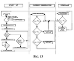
- Figure 13 is a flow chart of the three distinct phases of control of the operation of the fuel cell microfluidic feed system of the invention.
- The illustrative embodiment depicted in the figures, relates to an important application of a silicon flow connector based microfluidic feed system of this invention to a silicon fuel cell stack, through the anode compartments of which is circulated an aqueous solution of methanol, the molarity of which may be generally controlled to be in a range from 0.5 M to 2 M or even higher.
- Generally, for this type of application, the cell area size may be in the order of 20 to 100 cm2, appropriate for realizing a portable power source for recharging batteries of electronic instruments PCs, GPS systems, communications devices and alike.
- According to this embodiment, the overall functional diagram of the fuel feed system is depicted in Figure 1.
- According to a preferred embodiment of the system, the presence of three distinct reservoirs or cartridges is contemplated.
- A first cartridge C1 contains a certain volume of demineralized water, a second cartridge C2 contains a certain volume of methanol and in a third cartridge C3, depleted solution may be periodically drained for replenishing the system with fresh fuel solution (refresh operation).
- The supply cartridges C1 and C2, of H2O and CH3OH, respectively, have their discharge orifice controlled by respective release microvalves V1 and V2 and so is the inlet orifice of the waste solution cartridge C3 by a dedicated third drainage microvalve V3.
- As will be described in detail later, the
flow connector 1 defines at least a suction channel and a delivery channel that respectively connect the suction and delivery ports of a piezoelectric micropump P to an inlet manifold and to an outlet manifold of the fuel solution to and from the fuel cell stack FC. - The three microvalves V1, V2 and V3 and the piezoelectric micropump P are programmably driven by an electronic control unit CU.
- The opening of the normally closed microvalves V1, V2, V3 is commanded by circulating a current I through a thermoelectric actuator.
- The piezoelectric micropump P is driven by controlling the voltage and/or frequency applied to piezoelectric crystal fastened to a pump membrane that transmit vibrations to liquid contained in a pump chamber, having monodirectional suction valve and a monodirectional delivery valve.
- In Figure 2 is represented the resultant flow circuit of the system during a preliminary phase of filling the microfluidic fuel feed circuit with a solution of methanol in water, by gravity.
- During this filling step, the micropump P is not driven, while the release microvalves V1 and V2 that control the release of the content of the
water cartridge C 1 and of the methanol cartridge C2, are opened for precisely predetermined intervals of time in order to fill the system with a solution of methanol of the desired molarity (concentration). - Once the gravity filling of the fluid circuit of the system is complete, any current drive to the release microvalves V1 and V2 from the supply cartridges C1 and C2 is terminated causing the closure of both valves.
- An operating phase of energy conversion of chemical energy into electrical energy with circulation of an electric current in an external load circuit of the battery, is conducted by activating the micropump P, by the application of a controlled AC voltage to the piezoelectric crystal mechanically fastened to a membrane that transfers the vibration induced by the piezoelectric crystal to the fluid contained in the pump chamber connected to the inlet and output ports through monodirectional microvalves. The valve stopper may be a cantilever arm, normally abutting over the valve flow orifice.
- Figure 3 is a representation of the resultant flow circuit of the fuel feed system during a phase of energy conversion taking place in the microfuel cell stack FC.
- Of course, the energy conversion process occurring in the fuel cell FC through a direct methanol oxidation to carbon dioxide and water, is supported by the circulation of electric current in the load circuit connected to the terminal cathode (+) and to the terminal anode (-) of the fuel cell or multiple fuel cell stack.
- During this phase, mass transfer of the reactive methanol to the anodically polarized active sites (three phase sites) in the typically porous anode structure, is promoted by a continuous circulation of the methanol solution through the anodic compartment(s) of the fuel cell(s).
- As the concentration of methanol in the circulating solution progressively decreases in the volume of solution initially loaded in the system, the attendant decline of the cell voltage can be countered to some extent by increasing progressively the rate of circulation of the solution by increasing the drive voltage and/or changing the frequency that is applied to the piezoelectric crystal of the micropump.
- Once limit conditions of depletion of the circulating fuel solution are reached, as denounced by the dropping of the cell voltage to an established limit value, a refreshing of the circulating methanol solution is necessary.
- According to the embodiment shown, this phase of refreshing the fuel solution that is circulated through the fuel cell(s) anode compartment(s) is implemented by commanding a resultant configuration of the fluid circuit as depicted in Figure 4.
- The bleed microvalve V3 of depleted solution from the fuel cell circuit into the waste solution cartridge C3 is commanded open while continuing to pump the solution in circulation, and the methanol release microvalve (and successively and independently also the water release microvalve, if necessary) is also opened. Therefore, a bleeding of the solution into the waste solution cartridge C3 takes place, the bled volume of which is replenished with methanol drawn into the fuel cell circuit from the supply cartridge C2, until the cell voltage rises back according to the expected value, optionally opening also the water
supply microvalve V 1 for computed intervals of time. - This refresh operation is driven by a pressure difference that exists between suction and delivery channels to the micropump, and by a positive difference of free liquid levels between the supply cartridges C1 and C2 (initially full) and the waste solution recovery cartridge C3 (initially empty).
- Once desired refreshed conditions are achieved, the bleed microvalve V3 for discharging solution into the waste solution cartridge C3 is closed by interrupting any further electric current drive to it and thereafter also the methanol and/or eventually water supply microvalves V2 and V1 are closed to return the system to the normal operating configuration of Figure 3.
- Figure 5 depicts how the
silicon flow connector 1 carrying the functional components of the microfluidic feed system fixed onto thesilicon platform 1 is finally coupled onto the flat silicon surface of the end of a multicell, stack. On theflat surface 2 of the terminal element open aninlet manifold 2 through which the fuel feed solution is distributed to the anodes of the multiple cell stack and anoutlet manifold 3 from which the solution circulated by the main pump in the monofluidic fuel feed circuit returns to the pump, as graphically indicated by the dash line arrows. - The micromachined
monocrystalline silicon platform 1 constituting the flow connector is illustrated in Figures 6 and 7, respectively, a three-dimensional view from atop and a three-dimensional view from below. - The thickness of the
monocrystalline silicon platform 1 may generally be comprised between 0.2 mm and 0.5 mm or exceptionally even larger. - As identified in Figure 6 by phantom broken lines, and visible in Figure 7, two distinct channels or
extended recesses monocrystalline silicon platform 1. The depth of thechannels monocrystalline silicon platform 1. - As visible in both Figures 6 and 7, a plurality of through holes are formed in the monocrystalline silicon, reaching the
channels - The through
hole 7 coincides with the outlet port of the silicon microvalve module V1 fixed onto the platform, the inlet port of which couples with a discharge orifice of the water supply cartridge C1. - The through hole 8 coincides with the outlet port of the silicon microvalve module V2 fixed onto the platform, the inlet port of which couples to a discharge orifice of the water to the outlet of the water supply cartridge C1.
- The through
hole 9 at the inner end of thesuction channel 5 coincides with the suction port of the silicon micropump module p fixed onto the platform, the delivery port of which coincides with the throughhole 10 reaching thedelivery channel 6. - The through
hole 11 coincides with the inlet port of the silicon microvalve module V3 fixed onto the platform, the outlet port of which couples with the inlet orifice of the waste solution cartridge C1. - The
channels holes - The through holes and the
channels microchannels - The formation of protective and/or of retardant layers can normally be carried out in appropriate ovens, while the definition of the etch areas can be done by common photolithographic techniques.
- Figures 8a and 8b are three-dimensional views of a piezoelectric silicon micropump.
- The constitution and architecture of these silicon micropumps are well known to the skilled person. In the view of Figure 8a are depicted the
piezoelectric crystal transducer 12, to which a controlled AC voltage is applied (electrical connections not shown in the drawing), mechanically fastened onto amicromachined silicon membrane 13 closing an inner chamber of the pump. - In the view of Figure 8b is visible the
bottom closure 14 of the pump chamber and the monodirectional cantilever valve of thesuction port 9p and of the deliver port 10p of the pump chamber. - Of course, the fixing of the silicon piezoelectric micropump P onto the
silicon platform 1 as depicted in Figure 5, is done respecting a perfect alignment of thesuction port 9p of the pump with the throughhole 9 of thesilicon flow connector 1 and of the delivery port 10p of the pump with the throughhole 10 of theflow connector 1. - Figure 9a and Figure 9b are three-dimensional views of the two release and bleed silicon microvalves V1, V2 and V3 associated to the water supply cartridge C1 and to the methanol supply cartridge supply C2, respectively and to the waste solution recovery cartridge C3.
- The silicon microvalves may preferably be of the thermoelectric type including a thermoelectrically driven stopper. The heat input by Joule effect to open the valve stopper is provided by forcing a current through resistive elements (indicated in Figure 9a by the
metallization pattern 15 that define) pads for electrically connecting the valve to the control circuit. - The port 7b (8b) visible in the bottom side view of the microvalve module of Figure 9b, is aligned with the respective through
hole silicon flow connector 1, while the other port of thevalve 16 present on the top side, visible in Figure 9a, couples with the release or inlet orifice of the respective cartridge. - In Figure 10b is shown the bottom side of a cartridge reservoir from which is observable the
aperture 16c present in a stepped portion of the bottom of the cartridge overlapping a portion of the associated microvalve module such to couple with theupper side port 16 of the silicon microvalve module for controlling either the release of fluid from the cartridge or the bleeding of depleted solution into the cartridge. - While the silicon functional modules of the micropump and of the microvalves are permanently bonded onto the
monocrystalline silicon 1 constituting the flow connector of the feed system to the energy conversion device, the supply cartridges C1 and C2 and the waste solution cartridge C3 are coupled to the respective valve modules V1, V2 and V3 and held fast onto thesilicon platform 1 not in a permanent manner but preferably in a manner that will permit an easy and quick replacement of the cartridges with new ones. - To this end, the cartridges may be alignedly fixed on the silicon platform using a soft sigillant adhesive, for example silicone, or according to an alternative embodiment, each cartridge may include an interconnect element that may be permanently fixed in a leak proof manner onto the respective microvalve module and on the immediately adjacent surface of the silicon platform. The interconnect element or sub-module will have a male or female part of a snap-action coupling suitable to receive and retain a cartridge provided with a coordinately installed female or male part of the snap-action coupling.
- According to this embodiment, the coupling, besides hydraulically connecting the reservoir to the microfluidic fuel feed system will also provide an adequate mechanical retention of the replaceable cartridge onto the interconnect element, permanently fixed onto the silicon platform.
- The coupling part fitted at the bottom of the removable cartridge may include a removable or breakable seal that is removed or broken before or upon forcing the snap-action coupling parts to join together.
- The water supply cartridge (and optionally also the waste solution recovery cartridge) may be provided with a liquid impermeable gas vent for atmospheric pressure equalization and for prevent vacuum locks, according to common hydraulic practices.
- The control unit C1 can have any appropriate architecture depending on the design of the microfluidic solution feed system, design approach of the control system and relative deployment of sensors to monitor functioning parameters of the energy conversion device including, for example, the liquid content of the distinct water, methanol and waste recovery cartridges of the illustrated application for a fuel cell stack device.
- Generally, as depicted in Figure 11, a control unit of the control system of a fuel cell stack of the described embodiment, will include a multiplexed analog-to-digital converter ADC MUX and a bank of digital-to-analog converters DAC(s) for controlling the microvalves and the drive voltage SWG_VREF and frequency SWG_Freq , applied to the piezoelectric micropump.
- As depicted in Figure 12, a processing CORE of the control unit, will normally have an number of I/O pads and a memory MEMORY for storing the codes of the implemented control algorithm. A logic circuitry DIFF will produce the difference values between the selected monitored parameter value, as converted by the multiplexed analog-to-digital converter ADC MUX, with a certain reference value provided by the processing CORE, difference that will constitute an input value to the CORE circuitry.
- The flow chart of the three distinct phases of control of the generator of a fuel cell microfluidic feed system is shown in Figure 13.
Claims (6)
- A flow connector for a microfluidic system through which a solution of at least an oxidable compound is fed to a feed manifold (3) of an energy converting electrochemical device (FC) having a flat coupling area with said flow connector, the flow connector comprising
a monocrystalline silicon platform (1) having at least two distinct channels (5, 6) defined on the bottom side of the platform, on the top side of which a plurality of functional modules (P, C1, C2, C3, V1, V2, V3) of said microfluidic system are fixed in correspondence of respective through holes (7, 8, 9, 10, 11) communicating with a respective channel (5, 6);
a first channel (5) connecting two or more of said through holes (7, 8, 9); the second channel (6) connecting two or more other through holes (10, 11); through holes first (9) and second (10), respectively connected to said channels first (5) and second (6), coinciding with a suction port and with a delivery port, respectively, of a micropump module (P) fixed onto the silicon platform (1);
at least the through hole (9) coinciding with the suction port of the micropump (P) being connected through said first channel (5) to a through hole (7) coinciding with the outlet port of a first solvent release microvalve module (V1) from a first supply cartridge (C1) and to a through hole (8) coinciding with the outlet port of a second oxidable compound release microvalve module (V2) from a second supply cartridge (C2);
upon coupling the channelled (5, 6) bottom side of said silicon platform (1) to said flat coupling area of the device (FC), an inlet of said solution feed manifold (3) coinciding with said second channel (6). - The flow connectors according to claim 1, wherein said energy converting electrochemical device (FC) has a depleted solution discharge manifold (4) having an outlet in said flat coupling area coinciding with said first channel (5) of the silicon flow connector (1); and
said second channel (6) of the silicon flow connector communicates with a fifth through hole (11) coinciding with the inlet of a third solution discharge microvalve module (V3) for bleeding solution into a third cartridge (C3). - The flow connector according to claim 2, wherein said energy converting device (FC) is a single electrochemical cell or a stack of electrochemical cells, through an anode compartment or compartments of which an aqueous solution of a fuel belonging to the group composed of methanol and ethanol is circulated by said micropump (P).
- The flow connector according to claim 1, characterized in that said monocrystalline silicon platform (1) is a dice of a CZ or FZ monocrystalline silicon wafer of thickness comprised between 0.2 mm and 0.5 mm.
- A microfluidic feed system of a solution of at least an oxidable compound for an energy conversion electrochemical device (FC) having a flat coupling area in which a feed solution distributing manifold (3) inlet and a depleted solution discharge manifold (4) outlet open, characterized in that it comprises
a monocrystalline silicon platform (1) having at least two distinct channels (5, 6) defined on the bottom side of the platform, on the top side of which a plurality of functional modules (P, C1, C2, C3, V1, V2, V3) of said microfluidic system are fixed in correspondence of respective through holes (7, 8, 9, 10, 11) communicating with a respective channel (5, 6);
a first channel (5) connecting two or more of said through holes (7, 8, 9); the second channel (6) connecting two or more other through holes (10, 11); through holes first (9) and second (10), respectively connected to said channels first (5) and second (6), coinciding with a suction port and with a delivery port, respectively, of a micropump (P) module fixed onto the silicon platform (1);
at least the through hole (9) coinciding with the suction port of the micropump (P) being connected through said first channel (5) to a through hole (7) coinciding with the outlet port of a first solvent release microvalve module (V1) from a first supply cartridge (C1) and to a through hole (8) coinciding with the outlet port of a second oxidable compound release microvalve module (V2) from a second supply cartridge (C2);
said second channel (6) of the silicon flow connector communicates with a fifth through hole (11) coinciding with the inlet of a third solution discharge microvalve module (V3) for bleeding solution into a third depleted solution waste recovery cartridge (C3);
upon coupling the channelled (5, 6) bottom side of said silicon platform (1) to said flat coupling area of the device (FC), the inlet of said solution feed manifold (3) coinciding with said second channel (6) and the outlet of said depleted solution discharge manifold (4) coinciding with said first channel (5). - The microfluidic system according to claim 5, wherein said energy converting electrochemical device (FC) is a single electrochemical cell or a stack of electrochemical cells, through an anode compartment or compartments of which an aqueous solution of a fuel belonging to the group composed of methanol and ethanol is circulated by said micropump (P).
Priority Applications (2)
| Application Number | Priority Date | Filing Date | Title |
|---|---|---|---|
| EP06425001A EP1804326A1 (en) | 2006-01-02 | 2006-01-02 | Monocrystalline silicon flow connector and microfluidic system modularly built thereon for feeding a fuel solution to direct methanol fuel cell |
| US11/619,090 US8338049B2 (en) | 2006-01-02 | 2007-01-02 | Monocrystalline silicon flow connector and microfluidic system modularly built thereon for feeding a fuel solution to an energy converting device |
Applications Claiming Priority (1)
| Application Number | Priority Date | Filing Date | Title |
|---|---|---|---|
| EP06425001A EP1804326A1 (en) | 2006-01-02 | 2006-01-02 | Monocrystalline silicon flow connector and microfluidic system modularly built thereon for feeding a fuel solution to direct methanol fuel cell |
Publications (1)
| Publication Number | Publication Date |
|---|---|
| EP1804326A1 true EP1804326A1 (en) | 2007-07-04 |
Family
ID=36330882
Family Applications (1)
| Application Number | Title | Priority Date | Filing Date |
|---|---|---|---|
| EP06425001A Withdrawn EP1804326A1 (en) | 2006-01-02 | 2006-01-02 | Monocrystalline silicon flow connector and microfluidic system modularly built thereon for feeding a fuel solution to direct methanol fuel cell |
Country Status (2)
| Country | Link |
|---|---|
| US (1) | US8338049B2 (en) |
| EP (1) | EP1804326A1 (en) |
Families Citing this family (1)
| Publication number | Priority date | Publication date | Assignee | Title |
|---|---|---|---|---|
| US9714933B2 (en) | 2014-01-28 | 2017-07-25 | International Business Machines Corporation | Micro-droplet fluidic cell for fast ionic current detection using nanopores |
Citations (3)
| Publication number | Priority date | Publication date | Assignee | Title |
|---|---|---|---|---|
| EP1258937A1 (en) * | 2001-05-17 | 2002-11-20 | STMicroelectronics S.r.l. | Micro silicon fuel cell, method of fabrication and self-powered semiconductor device integrating a micro fuel cell |
| US20030031908A1 (en) * | 2001-08-09 | 2003-02-13 | Motorola, Inc. | Direct methanol fuel cell including a water recovery and re-circulation system and method of fabrication |
| US20050282054A1 (en) | 2004-06-16 | 2005-12-22 | Konica Minolta Holdings, Inc. | Fuel cell device |
Family Cites Families (1)
| Publication number | Priority date | Publication date | Assignee | Title |
|---|---|---|---|---|
| WO2005038956A2 (en) * | 2003-10-17 | 2005-04-28 | Neah Power Systems, Inc. | Nitric acid regeneration fuel cell systems |
-
2006
- 2006-01-02 EP EP06425001A patent/EP1804326A1/en not_active Withdrawn
-
2007
- 2007-01-02 US US11/619,090 patent/US8338049B2/en not_active Expired - Fee Related
Patent Citations (3)
| Publication number | Priority date | Publication date | Assignee | Title |
|---|---|---|---|---|
| EP1258937A1 (en) * | 2001-05-17 | 2002-11-20 | STMicroelectronics S.r.l. | Micro silicon fuel cell, method of fabrication and self-powered semiconductor device integrating a micro fuel cell |
| US20030031908A1 (en) * | 2001-08-09 | 2003-02-13 | Motorola, Inc. | Direct methanol fuel cell including a water recovery and re-circulation system and method of fabrication |
| US20050282054A1 (en) | 2004-06-16 | 2005-12-22 | Konica Minolta Holdings, Inc. | Fuel cell device |
Non-Patent Citations (2)
| Title |
|---|
| YAMAZAKI ET AL: "Application of MEMS technology to micro fuel cells", ELECTROCHIMICA ACTA, ELSEVIER SCIENCE PUBLISHERS, BARKING, GB, vol. 50, no. 2-3, 30 November 2004 (2004-11-30), pages 663 - 666, XP005148011, ISSN: 0013-4686 * |
| YAO ET AL: "Micro-electro-mechanical systems (MEMS)-based micro-scale direct methanol fuel cell development", ENERGY, PERGAMON PRESS, OXFORD, GB, vol. 31, no. 5, April 2006 (2006-04-01), pages 636 - 649, XP005210573, ISSN: 0360-5442 * |
Also Published As
| Publication number | Publication date |
|---|---|
| US20070178360A1 (en) | 2007-08-02 |
| US8338049B2 (en) | 2012-12-25 |
Similar Documents
| Publication | Publication Date | Title |
|---|---|---|
| JP6026542B2 (en) | High pressure gas system | |
| Yao et al. | Micro-electro-mechanical systems (MEMS)-based micro-scale direct methanol fuel cell development | |
| US10128509B2 (en) | Gas vent for electrochemical cell | |
| US7189471B2 (en) | Solid oxide MEMS-based fuel cells | |
| EP2774204B1 (en) | Immersible gaseous oxidant cathode for electrochemical cell system | |
| CN114207915A (en) | Device architecture for metal-air battery | |
| US6969664B2 (en) | Micro silicon fuel cell, method of fabrication and self-powered semiconductor device integrating a micro fuel cell | |
| CN102616720A (en) | Method and apparatus for filling a fuel container | |
| US20160208791A1 (en) | Apparatus for Pumping Fluid | |
| US20030134172A1 (en) | Integrated fuel cell and electrochemical power system employing the same | |
| Meng et al. | An active micro-direct methanol fuel cell with self-circulation of fuel and built-in removal of CO2 bubbles | |
| JP3706090B2 (en) | Multi-element thin film fuel cell | |
| WO2008051626A2 (en) | Hydrogen supply for micro fuel cells | |
| US8338049B2 (en) | Monocrystalline silicon flow connector and microfluidic system modularly built thereon for feeding a fuel solution to an energy converting device | |
| EP2216845B1 (en) | Fuel cell system | |
| CN104040769A (en) | Gas generator with combined gas flow valve and pressure relief vent | |
| WO2014186240A1 (en) | Charging system containing a fuel cell and battery with materials and methods of assembly for a fuel cell utilizing an anionic exchange membrane and fuel cell cartridge designs. | |
| KR100758243B1 (en) | Portable fuel cell system | |
| US20100000434A1 (en) | Micro fuel cell with membrane storage | |
| CN1996650B (en) | Microfuel cell with anchoring element reinforced electrolytic membrane and process for the manufacture thereof | |
| CN107394237A (en) | Fuel cell unit and fuel cell stack | |
| Yao et al. | Design of direct methanol micro fuel cell fluidic systems | |
| JP4594642B2 (en) | Fuel cell | |
| WO2025221964A1 (en) | Electrochemical device for electrical energy storage and hydrogen production | |
| Kroodsma et al. | A Fully-Enclosed Micro PEM Fuel Cell with Self-Regulated Fuel Delivery and Shut-Down |
Legal Events
| Date | Code | Title | Description |
|---|---|---|---|
| PUAI | Public reference made under article 153(3) epc to a published international application that has entered the european phase |
Free format text: ORIGINAL CODE: 0009012 |
|
| AK | Designated contracting states |
Kind code of ref document: A1 Designated state(s): AT BE BG CH CY CZ DE DK EE ES FI FR GB GR HU IE IS IT LI LT LU LV MC NL PL PT RO SE SI SK TR |
|
| AX | Request for extension of the european patent |
Extension state: AL BA HR MK YU |
|
| 17P | Request for examination filed |
Effective date: 20071213 |
|
| 17Q | First examination report despatched |
Effective date: 20080111 |
|
| AKX | Designation fees paid | ||
| RBV | Designated contracting states (corrected) |
Designated state(s): DE FR GB IT |
|
| REG | Reference to a national code |
Ref country code: DE Ref legal event code: 8566 |
|
| STAA | Information on the status of an ep patent application or granted ep patent |
Free format text: STATUS: THE APPLICATION HAS BEEN WITHDRAWN |
|
| 18W | Application withdrawn |
Effective date: 20081201 |