EP1804319A1 - Battery - Google Patents
Battery Download PDFInfo
- Publication number
- EP1804319A1 EP1804319A1 EP06127354A EP06127354A EP1804319A1 EP 1804319 A1 EP1804319 A1 EP 1804319A1 EP 06127354 A EP06127354 A EP 06127354A EP 06127354 A EP06127354 A EP 06127354A EP 1804319 A1 EP1804319 A1 EP 1804319A1
- Authority
- EP
- European Patent Office
- Prior art keywords
- battery according
- gasket
- sealing member
- safety vent
- cap
- Prior art date
- Legal status (The legal status is an assumption and is not a legal conclusion. Google has not performed a legal analysis and makes no representation as to the accuracy of the status listed.)
- Granted
Links
Images



Classifications
-
- H—ELECTRICITY
- H01—ELECTRIC ELEMENTS
- H01M—PROCESSES OR MEANS, e.g. BATTERIES, FOR THE DIRECT CONVERSION OF CHEMICAL ENERGY INTO ELECTRICAL ENERGY
- H01M10/00—Secondary cells; Manufacture thereof
- H01M10/05—Accumulators with non-aqueous electrolyte
- H01M10/052—Li-accumulators
-
- H—ELECTRICITY
- H01—ELECTRIC ELEMENTS
- H01M—PROCESSES OR MEANS, e.g. BATTERIES, FOR THE DIRECT CONVERSION OF CHEMICAL ENERGY INTO ELECTRICAL ENERGY
- H01M50/00—Constructional details or processes of manufacture of the non-active parts of electrochemical cells other than fuel cells, e.g. hybrid cells
- H01M50/30—Arrangements for facilitating escape of gases
-
- H—ELECTRICITY
- H01—ELECTRIC ELEMENTS
- H01M—PROCESSES OR MEANS, e.g. BATTERIES, FOR THE DIRECT CONVERSION OF CHEMICAL ENERGY INTO ELECTRICAL ENERGY
- H01M10/00—Secondary cells; Manufacture thereof
- H01M10/04—Construction or manufacture in general
- H01M10/0431—Cells with wound or folded electrodes
-
- H—ELECTRICITY
- H01—ELECTRIC ELEMENTS
- H01M—PROCESSES OR MEANS, e.g. BATTERIES, FOR THE DIRECT CONVERSION OF CHEMICAL ENERGY INTO ELECTRICAL ENERGY
- H01M10/00—Secondary cells; Manufacture thereof
- H01M10/05—Accumulators with non-aqueous electrolyte
- H01M10/058—Construction or manufacture
- H01M10/0587—Construction or manufacture of accumulators having only wound construction elements, i.e. wound positive electrodes, wound negative electrodes and wound separators
-
- H—ELECTRICITY
- H01—ELECTRIC ELEMENTS
- H01M—PROCESSES OR MEANS, e.g. BATTERIES, FOR THE DIRECT CONVERSION OF CHEMICAL ENERGY INTO ELECTRICAL ENERGY
- H01M50/00—Constructional details or processes of manufacture of the non-active parts of electrochemical cells other than fuel cells, e.g. hybrid cells
- H01M50/10—Primary casings; Jackets or wrappings
- H01M50/147—Lids or covers
- H01M50/166—Lids or covers characterised by the methods of assembling casings with lids
- H01M50/167—Lids or covers characterised by the methods of assembling casings with lids by crimping
-
- H—ELECTRICITY
- H01—ELECTRIC ELEMENTS
- H01M—PROCESSES OR MEANS, e.g. BATTERIES, FOR THE DIRECT CONVERSION OF CHEMICAL ENERGY INTO ELECTRICAL ENERGY
- H01M50/00—Constructional details or processes of manufacture of the non-active parts of electrochemical cells other than fuel cells, e.g. hybrid cells
- H01M50/10—Primary casings; Jackets or wrappings
- H01M50/147—Lids or covers
- H01M50/166—Lids or covers characterised by the methods of assembling casings with lids
- H01M50/171—Lids or covers characterised by the methods of assembling casings with lids using adhesives or sealing agents
-
- H—ELECTRICITY
- H01—ELECTRIC ELEMENTS
- H01M—PROCESSES OR MEANS, e.g. BATTERIES, FOR THE DIRECT CONVERSION OF CHEMICAL ENERGY INTO ELECTRICAL ENERGY
- H01M50/00—Constructional details or processes of manufacture of the non-active parts of electrochemical cells other than fuel cells, e.g. hybrid cells
- H01M50/10—Primary casings; Jackets or wrappings
- H01M50/183—Sealing members
- H01M50/184—Sealing members characterised by their shape or structure
-
- H—ELECTRICITY
- H01—ELECTRIC ELEMENTS
- H01M—PROCESSES OR MEANS, e.g. BATTERIES, FOR THE DIRECT CONVERSION OF CHEMICAL ENERGY INTO ELECTRICAL ENERGY
- H01M50/00—Constructional details or processes of manufacture of the non-active parts of electrochemical cells other than fuel cells, e.g. hybrid cells
- H01M50/10—Primary casings; Jackets or wrappings
- H01M50/183—Sealing members
- H01M50/186—Sealing members characterised by the disposition of the sealing members
-
- H—ELECTRICITY
- H01—ELECTRIC ELEMENTS
- H01M—PROCESSES OR MEANS, e.g. BATTERIES, FOR THE DIRECT CONVERSION OF CHEMICAL ENERGY INTO ELECTRICAL ENERGY
- H01M50/00—Constructional details or processes of manufacture of the non-active parts of electrochemical cells other than fuel cells, e.g. hybrid cells
- H01M50/10—Primary casings; Jackets or wrappings
- H01M50/183—Sealing members
- H01M50/19—Sealing members characterised by the material
- H01M50/193—Organic material
-
- H—ELECTRICITY
- H01—ELECTRIC ELEMENTS
- H01M—PROCESSES OR MEANS, e.g. BATTERIES, FOR THE DIRECT CONVERSION OF CHEMICAL ENERGY INTO ELECTRICAL ENERGY
- H01M50/00—Constructional details or processes of manufacture of the non-active parts of electrochemical cells other than fuel cells, e.g. hybrid cells
- H01M50/20—Mountings; Secondary casings or frames; Racks, modules or packs; Suspension devices; Shock absorbers; Transport or carrying devices; Holders
-
- H—ELECTRICITY
- H01—ELECTRIC ELEMENTS
- H01M—PROCESSES OR MEANS, e.g. BATTERIES, FOR THE DIRECT CONVERSION OF CHEMICAL ENERGY INTO ELECTRICAL ENERGY
- H01M50/00—Constructional details or processes of manufacture of the non-active parts of electrochemical cells other than fuel cells, e.g. hybrid cells
- H01M50/50—Current conducting connections for cells or batteries
- H01M50/572—Means for preventing undesired use or discharge
- H01M50/574—Devices or arrangements for the interruption of current
- H01M50/578—Devices or arrangements for the interruption of current in response to pressure
-
- H—ELECTRICITY
- H01—ELECTRIC ELEMENTS
- H01M—PROCESSES OR MEANS, e.g. BATTERIES, FOR THE DIRECT CONVERSION OF CHEMICAL ENERGY INTO ELECTRICAL ENERGY
- H01M2200/00—Safety devices for primary or secondary batteries
- H01M2200/10—Temperature sensitive devices
- H01M2200/106—PTC
-
- Y—GENERAL TAGGING OF NEW TECHNOLOGICAL DEVELOPMENTS; GENERAL TAGGING OF CROSS-SECTIONAL TECHNOLOGIES SPANNING OVER SEVERAL SECTIONS OF THE IPC; TECHNICAL SUBJECTS COVERED BY FORMER USPC CROSS-REFERENCE ART COLLECTIONS [XRACs] AND DIGESTS
- Y02—TECHNOLOGIES OR APPLICATIONS FOR MITIGATION OR ADAPTATION AGAINST CLIMATE CHANGE
- Y02E—REDUCTION OF GREENHOUSE GAS [GHG] EMISSIONS, RELATED TO ENERGY GENERATION, TRANSMISSION OR DISTRIBUTION
- Y02E60/00—Enabling technologies; Technologies with a potential or indirect contribution to GHG emissions mitigation
- Y02E60/10—Energy storage using batteries
-
- Y—GENERAL TAGGING OF NEW TECHNOLOGICAL DEVELOPMENTS; GENERAL TAGGING OF CROSS-SECTIONAL TECHNOLOGIES SPANNING OVER SEVERAL SECTIONS OF THE IPC; TECHNICAL SUBJECTS COVERED BY FORMER USPC CROSS-REFERENCE ART COLLECTIONS [XRACs] AND DIGESTS
- Y02—TECHNOLOGIES OR APPLICATIONS FOR MITIGATION OR ADAPTATION AGAINST CLIMATE CHANGE
- Y02P—CLIMATE CHANGE MITIGATION TECHNOLOGIES IN THE PRODUCTION OR PROCESSING OF GOODS
- Y02P70/00—Climate change mitigation technologies in the production process for final industrial or consumer products
- Y02P70/50—Manufacturing or production processes characterised by the final manufactured product
Definitions
- the invention relates to a battery.
- Lithium secondary batteries may be classified as cylindrical or rectangular according to their exterior shape.
- a cylindrical lithium secondary battery has a built-in current limiting structure in a cap assembly to stop a current generating reaction when an internal pressure of the battery is raised above a certain limit and when there is a risk of explosion. Accordingly, the structure enhances the safety of the lithium secondary battery.
- a related art cylindrical lithium secondary battery 10, as shown in Figure 7, is composed of an electrode assembly (not shown) in the interior, a cylindrical can 30 that receives the electrode assembly and an electrolyte, and a cap assembly 40 that is assembled in the upper side of the cylindrical can 30 and seals the cylindrical can 30 to divert the current generated from the electrode assembly to an external device.
- the related art cap assembly 40 is configured to have the following elements be sequentially inserted into the cylindrical can 30.
- the elements include a gasket, a safety vent, a current isolation member, a secondary protective element, and a cap up.
- a rim of the cylindrical can 30 is crimped to keep the elements in place and prevent the gas and the electrolyte from leaking.
- aspects of the present invention relate to the problems as described above, and/or other problems, and aspects of the present invention improve tightness or a seal in a battery by inserting or forming an adhesive material between a safety vent and a gasket, and/or between the safety vent and a shaped can to reduce or prevent the gas or the electrolyte of the battery from leaking.
- Other aspects of the present invention have other benefits.
- the lithium secondary battery according to aspects of the present invention includes a electrode assembly, a cylindrical can to receive the electrode assembly, a cap assembly which closes an opening of the can and includes a current isolation member and a cap up connected to the current isolation member, a gasket disposed between the cap assembly and the can to maintain tightness or an airtight seal, and a supporting sealing member formed between the safety vent and the gasket.
- the supporting sealing member may be formed of at least one of a rubber, a silicone, and a polymer.
- the supporting sealing member according to an aspect of the present invention may have an annular shape with a round hole in the centre.
- the supporting sealing member may comprise an exterior end formed in a width direction and extended over an interface where the gasket and the cap assembly contact each other.
- the supporting sealing member according to an aspect of the present invention may be formed between the gasket and the cylindrical can.
- the supporting sealing member may include an adhesive layer, wherein the adhesive layer is formed on a double sided tape or is formed by solidification after a fluid amorphous adhesive is inserted between the safety vent and the gasket.
- the gasket according to an aspect of the present invention may be formed of at least one of a polyethylene, a polyethylene, and a polyimide.
- the cap assembly according to an aspect of the present invention may be formed as a single piece that includes the current isolation member and the cap up.
- the current isolation member according to an aspect to the present invention may include at least one of copper or a copper alloy, and the conductive layer may be formed by a plating process.
- the secondary protective element according to an aspect to the present invention may be attached to an upper side of the safety vent.
- the secondary protective element according to an aspect to the present invention may be a positive temperature coefficient (PTC) element formed of a layer of resin and carbon powder.
- PTC positive temperature coefficient
- a rechargeable battery includes a receptacle having an opened end and containing electrolyte, a cap to close the opened end, a gasket interposed between the receptacle and the cap, and a sealer interposed between the receptacle and the cap to hinder leakage of any produced gas and/or capillary phenomenon leakage of electrolyte.
- a rechargeable battery includes a can, a safety vent to couple with the can, a gasket interposed between the can and the safety vent, and a sealing member interposed between the safety vent and the gasket and/or the can and the gasket to enhance a seal and strengthen the attachment thereof.
- a cylindrical secondary battery 100 (cylindrical lithium secondary battery or the battery) includes an electrode assembly 200, a cylindrical can 300 (or receptacle) which receives the electrode assembly 200 and an electrolyte, and a cap assembly 400 (or a cap) which is assembled in the upper side of the cylindrical can 300 to seal the cylindrical can 300 and divert the current generated from the electrode assembly 200 to an external device.
- the electrode assembly 200 is formed into a jelly roll shape by winding a positive electrode plate 210 to which the positive electrode active material layer is coated, a negative electrode plate 220, to which the negative electrode active material layer is coated, and a separator 230, which is positioned between the positive electrode plate 210 and the negative electrode plate 220.
- the positive electrode plate 210 is a thin film having good conductivity.
- the positive electrode plate 210 includes a positive current collector that includes an aluminium (Al) foil and a positive electrode active material layer which is coated to both surfaces of the positive electrode plate 210.
- the positive current collector has a region on which the positive electrode active material is not coated. Such a positive uncoated region is formed at both ends of the positive electrode plate 210.
- One end of the positive uncoated region is made of Al and is connected to a positive tap 215 which protrudes away from the electrode assembly 200 (in Figure 1, the upward or outward direction from the interior) and has a specific length.
- the negative electrode plate 220 is a thin film, such as a conductive metal.
- the positive electrode plate 220 includes a negative current collector that includes a copper (Cu) foil and/or a nickel (Ni) foil and a negative electrode active material layer which is coated to both surfaces of the negative electrode plate.
- the negative current collector has a region on which the negative electrode active material is not coated.
- Such a negative uncoated region is formed at both ends of the negative electrode plate 220.
- One end of the negative uncoated region is made of Ni and is connected to a negative tap 225 which protrudes away from the electrode assembly 200 (In Figure 1, the downward or outward direction from the interior) and has a specific length.
- respective insulating plates 241, 245 may be provided to prevent a contact of the electrode assembly 200 with the respective cap assembly 400 and the cylindrical can 300.
- the cylindrical can 300 (or can) includes a cylindrical side plate 310 which has a specific diameter, and a bottom plate 320 which seals off the bottom side of the cylindrical side plate 310. Accordingly, a predetermined space is formed within the cylindrical can 300 in which the cylindrical electrode assembly 200 is accommodated.
- the cylindrical can 300 also includes an opening, in which the electrode assembly 200 is inserted, on the upper side of the cylindrical side plate 310.
- the cylindrical can 300 self serves as a negative electrode of the lithium secondary battery 100 since the negative tap 225 is connected to the central region of the bottom plate 320 of the cylindrical can 300.
- the cylindrical can 300 is made of aluminium (Al), iron (Fe), or an alloy thereof.
- the cylindrical can 300 includes a clipping 330 (or a bent portion as shown in Figure 2) which is bent inward to press down on the upper side of the cap assembly 400 (as shown in Figure 1). Also, the cylindrical can 300 includes a beading 340 which is formed at a position spaced from the clipping 330 by a specific distance corresponding to a thickness of the cap assembly 400. The beading 340 is concaved to press (or help support) the bottom side of the cap assembly 400.
- the cap assembly 400 includes a safety vent 410, a current isolation member 420, a secondary protective element 480, and a cap up 490 (also referred to as a cap top).
- the safety vent 410 is positioned towards the lower side of the cap assembly 400.
- the safety vent 410 includes a protrusion that protrudes from the central region (in Figures 1 and 2, the downward direction or the inward direction towards the interior of the can 300).
- the protrusion is designed to be transformed by being pushed upward (or the outward direction away from the interior of the can 300) by a pressure when a gas is generated in the cylindrical lithium secondary battery 100.
- the positive electrode plate 210 and the negative electrode plate 220 of the electrode assembly 200 are electrically connected to the cap assembly 400 and the can 300, respectively.
- the positive tap 215 is welded onto the lower surface of the safety vent 410 to electrically connect the safety vent 410 and the positive electrode plate 210.
- the negative tap 225 is contacted with the can 300 to electrically connect the can 300 and the negative electrode plate 220.
- the cap assembly 400 may include a single piece element that combines the current isolation member 420 and the safety vent 410.
- the current isolation member 420 and the secondary protective element 480 may be laminated onto the safety vent 410 in sequence, and the cap up 490 may be applied thereon to form the cap assembly 400.
- the safety vent 410, the current isolation member 420, and the secondary protective element 480 may be formed as a single piece to reduce the volume, the weight, and the contact resistance.
- the current isolating member 420 includes a lower conductive thin film 422, a via hole 425, an upper conductive thin film 426, and a main body 428.
- the conductive thin films 422, 426 of the current isolation member 420 are copper, a copper alloy, or any combination thereof. Copper is a good conductor and has very high conductivity.
- the conductive thin films (or layers) can be made by a plating process for its ease of thickness control and simplicity.
- the secondary protective element 480 may be attached to the safety vent 410 as shown in Figure 1.
- the current isolation member 420 may be seated on the upper surface of the safety vent 410 and electrically connected thereto. Accordingly, current flowing into the safety vent 410 flows through the lower conductive thin film 422, along the via hole 425, and the upper conductive thin film 426. Also, the secondary protective element 480 is seated onto the upper side of the current isolation member 420 and electrically connected to the upper conductive thin film 426 for the current to flow.
- cap up 490 is electrically connected to the upper side of the secondary protective element 480 for the current to flow from the secondary protective element 480 to the outside of the lithium secondary battery 100.
- the secondary protective element 480 may be formed of a positive temperature coefficient (PTC) element comprising a resin and a carbon powder.
- PTC positive temperature coefficient
- the resin serves as a binder and the carbon powder serves as a conductor. If the temperature is raised due to a short, an over-charge, and/or an over-discharge of the battery 100, the flow of current will be cut because the resin will expand and distances between the carbon powder will lengthen.
- a gasket 305 is formed between the cylindrical can 300 and the cap assembly 400.
- the material of the gasket 305 may be a polymer and/or a resin.
- the gasket 305 may be polyethylene (PE), polypropylene (PP), polyimide (PI), or any combination thereof.
- Polyethylene is light and has low density. It is easily extended because the molecular arrangement is not rigid. Polyethylene has a relatively low tensile strength and high impact-resistance. Polyethylene is easy to process and use. Also, polyethylene has good electric insulation properties because it is made of repeating units of CH 2 only, and is well suited as a high frequency insulation material because it is symmetrical about a chain of carbon (C).
- Polypropylene is generated together with ethylene when naphtha is decomposed.
- Polypropylene has an isotactic structure and is arranged in the same direction as that of the methyl group. Although crystallinity of polypropylene is high, it is reduced after forming.
- the electrical properties of polypropylene and polyimide are similar to those of polyethylene.
- a supporting sealing member 500 (also referred to as a sealing support member) is formed between the gasket 305 and the safety vent 410.
- the supporting sealing member 500 may be formed of rubber, silicone, polymer, or any combination thereof.
- the supporting sealing member 500 may be annular in shape with a round hole in the centre.
- the supporting sealing member 500 may be implemented in any of various possible forms. It may be formed as an annular ring, an annular ring with a coating of adhesives, an adhesive film, a tape, or any combinations thereof. Also, several of the supporting sealing members 500 may be used, each of which may be the same or different in form.
- the supporting sealing member 500 may be an annular ring with an adhesive layer coating having a predetermined adhesiveness.
- the supporting sealing member 500 functions to attach the safety vent 410 and the gasket 305 together.
- the supporting sealing member 500 may be a double-sided tape, wherein the adhesive layer (or material) is applied to the two (or separate) sides of a base material, such as tape.
- the base is a silicon (Si) resin (or silicone).
- the silicon resin may be a thermoplastic synthetic resin, and may be a polymer of an organic derivative of the silicon.
- a normal plastic has a backbone formed of carbon.
- the silicon resin has a backbone formed of silicon in the shape of a siloxane bond (Si-O bond) with added organic groups such as phenyl and/or hydroxyl groups.
- the silicon resin has a covering power (coverage or spreading power) sufficient for use as a mould release.
- the silicon resin has good insulating property, and has the best heat resistance when the attached organic group is of a methyl group. When the methyl group is replaced with an alkyl group or an aryl group, mechanical strength of the silicon resin is increased but the electric performance is weakened.
- silicon resin is an insulation material which resists high temperatures for a long time. Therefore, silicon resin is suitable for the base of the double sided tape, since the silicon resin has good covering power, good thermal-resistance, and good insulating property.
- the supporting sealing member 500 may be implemented as an adhesive layer formed from an amorphous adhesive possessing fluidity.
- the cylindrical can 300 and the gasket 305, or the safety vent 410 and the gasket 305 may be strongly attached to each other by applying the adhesive.
- a gap between the cylindrical can 300 and the gasket 305, or between the safety vent 410 and the gasket 305 may be filled or sealed by applying the adhesive.
- the adhesive may be a liquid phase adhesive, a gel adhesive, or something similar.
- the supporting sealing member 500 may be placed between the can 300 and the cap assembly 400.
- the supporting sealing member 500 is placed between the gasket 305 and the safety vent 410.
- the supporting sealing member 500 may be lengthened so that an exterior end in the width direction thereof is extended and is formed over a portion or a periphery of the cap assembly 400. That is, referring to Figure 5, the supporting sealing member 500 may be configured so that the radius of the supporting sealing member 500 is extended and the supporting sealing member 500 is made to surround the lateral side (outside annular edge) of the cap assembly 400 by a portion 500a.
- the upper side of the battery 100 is closed by crimping the upper opening of the cylindrical can 300 to form a crimping 330 that faces inward in the direction of the gasket 305. Accordingly, the cylindrical can 300, the gasket 305, and the cap up 490 are pressed on the outside of the gasket 305 and the gasket 305 and the safety vent 410 are tightened (or pressed) to the inside of the gasket 305.
- the upper end opening of the cylindrical can 300 and the gasket 305 are strongly tightened (or pressed together) on the outside.
- the radius of the supporting sealing member 500 may be extended to cover the lateral surface of the cap assembly 400.
- a supporting sealing member 502 similar to the supporting sealing member 500 may be formed between the cylindrical can 300 and the gasket 305.
- the supporting sealing member 502 is formed where the opening of the cylindrical can 300 and the gasket 305 are attached (or pressed) on a side opposite the gasket 305 from the supporting sealing member 500 that is formed between the gasket 305 and the safety vent 410.
- the supporting sealing member 502 is formed between the can 300 and the gasket 305 while the supporting sealing member 500 is formed between the safety vent 410 and the gasket 305.
- One or both of the supporting sealing members 500, 502 may be made of rubber, silicone, polymer, or any combination thereof.
- the supporting sealing member 502 may include an adhesive layer which has a predetermined adhesiveness, may have the adhesive layer formed on a double sided tape, or may be an amorphous adhesive which has fluidity.
- the supporting sealing member 500 and the supporting sealing member 502 may be formed in a similar or different manner.
- the supporting sealing member 502 has an annular shape with a hole in the centre, which is the same as that of the supporting sealing member 500 (adhesive layer) formed between the gasket 305 and the safety vent 410. It is advantageous, but not required, that the convex (or protrusion) of the safety vent 410 is positioned into the lithium secondary battery 100 so that the safety vent 410 is deformable upward (or outward) when the internal pressure is raised by gas generated in the battery.
- the supporting sealing member 500 is formed between the gasket 305 and the safety vent 410.
- the supporting sealing member 500 is a double sided tape, wherein one side surface of the double sided tape is attached to a part of the gasket 305 and the other side surface of the double sided tape is attached to a part of the safety vent 410.
- the supporting sealing member 500 is a liquid phase or gel adhesive, then the supporting sealing member 500 is attached to the same position as that of the double sided tape to connect (glue or seal) the gasket 305 and the safety vent 410 together while drying.
- the supporting sealing member 500 is formed between the gasket 305 and the safety vent 410, and the supporting sealing member 502 is formed between a part of the gasket 305 and a part of the inner surface of the upper end opening 330 of the can 300.
- the supporting sealing member 500 is formed over more of the interface where the cap assembly 400 and the gasket 305 are in contact, by extending the supporting sealing member 500 by a portion 500a.
- the battery 100 accommodates the electrode assembly 400 and tightens an edge thereof over the cap assembly 400 by a crimping 330 (or a crimp) that transforms (or bends) the upper end opening of the cylindrical can 300 towards the inside of the lithium secondary battery 100.
- a crimping 330 or a crimp
- gas or electrolyte will leak through a slight gap (or a tight gap) present between the gasket 305 and the safety vent 410, between the gasket 305 and the upper end opening 330 of the can 300, and/or the gasket 305 and the electrode assembly 400.
- gasket 305 and the safety vent 410 between the gasket 305 and the upper end opening 330 of the can 300, and/or the gasket 305 and the electrode assembly 400.
- supporting sealing members 500 and/or 502 are formed at the slight gap to reduce or prevent the gas and/or electrolyte from going through the slight gap.
- the supporting sealing members 500 and/or 502 seal the gap between the supporting sealing member 500, 502 and the cap assembly 400 and the cylindrical can 300, respectively, and/or tighten the attachment. Therefore, the gas leakage is reduced and/or prevented.
- the supporting sealing members 500 and/or 502 that are formed at the slight gap reduce and/or prevent leakage of the electrolyte reaching the gap that may be caused by cohesive power of the electrolyte and capillary phenomenon. Accordingly, electrolyte leakage is reduced and/or prevented.
- the present invention is applicable to any type or shaped batteries, including any that are rechargeable or non-rechargeable and/or rectangular or hexagonal.
- the adhesives or the tape may be preformed on the cap assembly, the gasket, and/or the can.
- One or more of the supporting sealing members are formed between the safety vent and the gasket, and/or between the cylindrical can and the gasket to enhance a seal and tightness therebetween and safety of the lithium secondary battery.
Landscapes
- Chemical & Material Sciences (AREA)
- Chemical Kinetics & Catalysis (AREA)
- Electrochemistry (AREA)
- General Chemical & Material Sciences (AREA)
- Engineering & Computer Science (AREA)
- Manufacturing & Machinery (AREA)
- Secondary Cells (AREA)
- Sealing Battery Cases Or Jackets (AREA)
- Gas Exhaust Devices For Batteries (AREA)
- Connection Of Batteries Or Terminals (AREA)
Abstract
Description
- The invention relates to a battery.
- Lithium secondary batteries may be classified as cylindrical or rectangular according to their exterior shape. A cylindrical lithium secondary battery has a built-in current limiting structure in a cap assembly to stop a current generating reaction when an internal pressure of the battery is raised above a certain limit and when there is a risk of explosion. Accordingly, the structure enhances the safety of the lithium secondary battery.
- A related art cylindrical lithium
secondary battery 10, as shown in Figure 7, is composed of an electrode assembly (not shown) in the interior, acylindrical can 30 that receives the electrode assembly and an electrolyte, and acap assembly 40 that is assembled in the upper side of thecylindrical can 30 and seals the cylindrical can 30 to divert the current generated from the electrode assembly to an external device. - The related
art cap assembly 40 is configured to have the following elements be sequentially inserted into thecylindrical can 30. The elements include a gasket, a safety vent, a current isolation member, a secondary protective element, and a cap up. Once each element is inserted into the cylindrical can 30 in the order discussed above, a rim of thecylindrical can 30 is crimped to keep the elements in place and prevent the gas and the electrolyte from leaking. However, with only this configuration, there is a risk of separation between the safety vent and the gasket and a risk of leakage when the internal pressure of thebattery 10 is raised since a complete seal is not formed. Also, if the electrolyte flows into a slight gap between thecap assembly 40 and the gasket or between the gasket and the cylindrical can 30, due to an impact, a jolt, etc., there is a risk of electrolyte leakage out of the battery by interaction of a capillary phenomenon and a cohesive power of the electrolyte, etc. - Accordingly, aspects of the present invention relate to the problems as described above, and/or other problems, and aspects of the present invention improve tightness or a seal in a battery by inserting or forming an adhesive material between a safety vent and a gasket, and/or between the safety vent and a shaped can to reduce or prevent the gas or the electrolyte of the battery from leaking. Other aspects of the present invention have other benefits.
- The lithium secondary battery according to aspects of the present invention includes a electrode assembly, a cylindrical can to receive the electrode assembly, a cap assembly which closes an opening of the can and includes a current isolation member and a cap up connected to the current isolation member, a gasket disposed between the cap assembly and the can to maintain tightness or an airtight seal, and a supporting sealing member formed between the safety vent and the gasket.
- Also, the supporting sealing member according to an aspect of the present invention may be formed of at least one of a rubber, a silicone, and a polymer.
- Also, the supporting sealing member according to an aspect of the present invention may have an annular shape with a round hole in the centre.
- Also, the supporting sealing member according to an aspect of the present invention may comprise an exterior end formed in a width direction and extended over an interface where the gasket and the cap assembly contact each other.
- Also, the supporting sealing member according to an aspect of the present invention may be formed between the gasket and the cylindrical can.
- Also, the supporting sealing member according to an aspect of the present invention may include an adhesive layer, wherein the adhesive layer is formed on a double sided tape or is formed by solidification after a fluid amorphous adhesive is inserted between the safety vent and the gasket.
- Also, the gasket according to an aspect of the present invention may be formed of at least one of a polyethylene, a polyethylene, and a polyimide.
- Also, the cap assembly according to an aspect of the present invention may be formed as a single piece that includes the current isolation member and the cap up.
- Also, the current isolation member according to an aspect to the present invention may include at least one of copper or a copper alloy, and the conductive layer may be formed by a plating process.
- Also, the secondary protective element according to an aspect to the present invention may be attached to an upper side of the safety vent.
- Also, the secondary protective element according to an aspect to the present invention may be a positive temperature coefficient (PTC) element formed of a layer of resin and carbon powder.
- According to an aspect of the present invention, a rechargeable battery includes a receptacle having an opened end and containing electrolyte, a cap to close the opened end, a gasket interposed between the receptacle and the cap, and a sealer interposed between the receptacle and the cap to hinder leakage of any produced gas and/or capillary phenomenon leakage of electrolyte.
- According to an aspect of the present invention, a rechargeable battery includes a can, a safety vent to couple with the can, a gasket interposed between the can and the safety vent, and a sealing member interposed between the safety vent and the gasket and/or the can and the gasket to enhance a seal and strengthen the attachment thereof.
- Additional aspects and/or advantages of the invention will be set forth in part in the description which follows and, in part, will be obvious from the description, or may be learned by practice of the invention.
- The invention will now be described, by way of example, with reference to the accompanying drawings, of which:
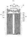
- Figure 1 illustrates a cross-sectional view of a lithium secondary battery according to the present invention;
- Figure 2 illustrates an exploded view of the Figure 1 battery;
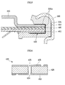
- Figure 3 illustrates a cross-sectional portion of one embodiment of a lithium secondary battery according to the present invention;
- Figure 4 illustrates a cross-sectional portion of a second embodiment of a lithium secondary battery according to the present invention;
- Figure 5 illustrates a cross-sectional portion of a third embodiment of a secondary battery according to the present invention;
- Figure 6 illustrates a cross-sectional view of a current isolation member used in the embodiments of the invention; and
- Figure 7 illustrates a perspective view of a related art lithium secondary battery.
- In the drawings, like reference numerals refer to the like elements throughout.
- As shown in Figure 1, a cylindrical secondary battery 100 (cylindrical lithium secondary battery or the battery) includes an
electrode assembly 200, a cylindrical can 300 (or receptacle) which receives theelectrode assembly 200 and an electrolyte, and a cap assembly 400 (or a cap) which is assembled in the upper side of the cylindrical can 300 to seal thecylindrical can 300 and divert the current generated from theelectrode assembly 200 to an external device. - As shown in Figure 1, the
electrode assembly 200 is formed into a jelly roll shape by winding apositive electrode plate 210 to which the positive electrode active material layer is coated, anegative electrode plate 220, to which the negative electrode active material layer is coated, and aseparator 230, which is positioned between thepositive electrode plate 210 and thenegative electrode plate 220. Thepositive electrode plate 210 is a thin film having good conductivity. In this example, thepositive electrode plate 210 includes a positive current collector that includes an aluminium (Al) foil and a positive electrode active material layer which is coated to both surfaces of thepositive electrode plate 210. The positive current collector has a region on which the positive electrode active material is not coated. Such a positive uncoated region is formed at both ends of thepositive electrode plate 210. - One end of the positive uncoated region is made of Al and is connected to a
positive tap 215 which protrudes away from the electrode assembly 200 (in Figure 1, the upward or outward direction from the interior) and has a specific length. - Also, the
negative electrode plate 220 is a thin film, such as a conductive metal. In this example, thepositive electrode plate 220 includes a negative current collector that includes a copper (Cu) foil and/or a nickel (Ni) foil and a negative electrode active material layer which is coated to both surfaces of the negative electrode plate. The negative current collector has a region on which the negative electrode active material is not coated. Such a negative uncoated region is formed at both ends of thenegative electrode plate 220. One end of the negative uncoated region is made of Ni and is connected to anegative tap 225 which protrudes away from the electrode assembly 200 (In Figure 1, the downward or outward direction from the interior) and has a specific length. In the upper side and the lower side of theelectrode assembly 200, respectiveinsulating plates electrode assembly 200 with therespective cap assembly 400 and thecylindrical can 300. - As shown in Figures 1 and 2, the cylindrical can 300 (or can) includes a
cylindrical side plate 310 which has a specific diameter, and abottom plate 320 which seals off the bottom side of thecylindrical side plate 310. Accordingly, a predetermined space is formed within thecylindrical can 300 in which thecylindrical electrode assembly 200 is accommodated. The cylindrical can 300 also includes an opening, in which theelectrode assembly 200 is inserted, on the upper side of thecylindrical side plate 310. The cylindrical can 300 self serves as a negative electrode of the lithiumsecondary battery 100 since thenegative tap 225 is connected to the central region of thebottom plate 320 of the cylindrical can 300. In this example, the cylindrical can 300 is made of aluminium (Al), iron (Fe), or an alloy thereof. - Furthermore, the cylindrical can 300 includes a clipping 330 (or a bent portion as shown in Figure 2) which is bent inward to press down on the upper side of the cap assembly 400 (as shown in Figure 1). Also, the cylindrical can 300 includes a beading 340 which is formed at a position spaced from the
clipping 330 by a specific distance corresponding to a thickness of thecap assembly 400. The beading 340 is concaved to press (or help support) the bottom side of thecap assembly 400. - As shown in Figures 1 and 2, the
cap assembly 400 includes asafety vent 410, acurrent isolation member 420, a secondaryprotective element 480, and a cap up 490 (also referred to as a cap top). Thesafety vent 410 is positioned towards the lower side of thecap assembly 400. Thesafety vent 410 includes a protrusion that protrudes from the central region (in Figures 1 and 2, the downward direction or the inward direction towards the interior of the can 300). The protrusion is designed to be transformed by being pushed upward (or the outward direction away from the interior of the can 300) by a pressure when a gas is generated in the cylindrical lithiumsecondary battery 100. Also, thepositive electrode plate 210 and thenegative electrode plate 220 of theelectrode assembly 200 are electrically connected to thecap assembly 400 and thecan 300, respectively. For example, thepositive tap 215 is welded onto the lower surface of thesafety vent 410 to electrically connect thesafety vent 410 and thepositive electrode plate 210. Similarly, thenegative tap 225 is contacted with thecan 300 to electrically connect thecan 300 and thenegative electrode plate 220. - The
cap assembly 400 may include a single piece element that combines thecurrent isolation member 420 and thesafety vent 410. Thecurrent isolation member 420 and the secondaryprotective element 480 may be laminated onto thesafety vent 410 in sequence, and the cap up 490 may be applied thereon to form thecap assembly 400. Alternatively, thesafety vent 410, thecurrent isolation member 420, and the secondaryprotective element 480 may be formed as a single piece to reduce the volume, the weight, and the contact resistance. - In the example shown in Figures 2 and 6, the current isolating
member 420 includes a lower conductivethin film 422, a viahole 425, an upper conductivethin film 426, and amain body 428. In one example, the conductivethin films current isolation member 420 are copper, a copper alloy, or any combination thereof. Copper is a good conductor and has very high conductivity. Alternatively, the conductive thin films (or layers) can be made by a plating process for its ease of thickness control and simplicity. - The secondary
protective element 480 may be attached to thesafety vent 410 as shown in Figure 1. Thecurrent isolation member 420 may be seated on the upper surface of thesafety vent 410 and electrically connected thereto. Accordingly, current flowing into thesafety vent 410 flows through the lower conductivethin film 422, along the viahole 425, and the upper conductivethin film 426. Also, the secondaryprotective element 480 is seated onto the upper side of thecurrent isolation member 420 and electrically connected to the upper conductivethin film 426 for the current to flow. - Also, the cap up 490 is electrically connected to the upper side of the secondary
protective element 480 for the current to flow from the secondaryprotective element 480 to the outside of the lithiumsecondary battery 100. - The secondary
protective element 480 may be formed of a positive temperature coefficient (PTC) element comprising a resin and a carbon powder. Here, the resin serves as a binder and the carbon powder serves as a conductor. If the temperature is raised due to a short, an over-charge, and/or an over-discharge of thebattery 100, the flow of current will be cut because the resin will expand and distances between the carbon powder will lengthen. - In the examples shown in Figures 1 and 2, a
gasket 305 is formed between thecylindrical can 300 and thecap assembly 400. The material of thegasket 305 may be a polymer and/or a resin. For instance, thegasket 305 may be polyethylene (PE), polypropylene (PP), polyimide (PI), or any combination thereof. - Polyethylene is light and has low density. It is easily extended because the molecular arrangement is not rigid. Polyethylene has a relatively low tensile strength and high impact-resistance. Polyethylene is easy to process and use. Also, polyethylene has good electric insulation properties because it is made of repeating units of CH2 only, and is well suited as a high frequency insulation material because it is symmetrical about a chain of carbon (C).
- Polypropylene is generated together with ethylene when naphtha is decomposed. Polypropylene has an isotactic structure and is arranged in the same direction as that of the methyl group. Although crystallinity of polypropylene is high, it is reduced after forming. The electrical properties of polypropylene and polyimide are similar to those of polyethylene.
- As shown in Figures 2 and 3, a supporting sealing member 500 (also referred to as a sealing support member) is formed between the
gasket 305 and thesafety vent 410. The supportingsealing member 500 may be formed of rubber, silicone, polymer, or any combination thereof. The supportingsealing member 500 may be annular in shape with a round hole in the centre. - The supporting
sealing member 500 may be implemented in any of various possible forms. It may be formed as an annular ring, an annular ring with a coating of adhesives, an adhesive film, a tape, or any combinations thereof. Also, several of the supporting sealingmembers 500 may be used, each of which may be the same or different in form. - The supporting
sealing member 500 may be an annular ring with an adhesive layer coating having a predetermined adhesiveness. The supportingsealing member 500 functions to attach thesafety vent 410 and thegasket 305 together. Here, the supporting sealingmember 500 may be a double-sided tape, wherein the adhesive layer (or material) is applied to the two (or separate) sides of a base material, such as tape. Preferably, the base is a silicon (Si) resin (or silicone). - The silicon resin (or silicone) may be a thermoplastic synthetic resin, and may be a polymer of an organic derivative of the silicon. Generally, a normal plastic has a backbone formed of carbon. However, the silicon resin has a backbone formed of silicon in the shape of a siloxane bond (Si-O bond) with added organic groups such as phenyl and/or hydroxyl groups. The silicon resin has a covering power (coverage or spreading power) sufficient for use as a mould release. Also, the silicon resin has good insulating property, and has the best heat resistance when the attached organic group is of a methyl group. When the methyl group is replaced with an alkyl group or an aryl group, mechanical strength of the silicon resin is increased but the electric performance is weakened. Also, silicon resin is an insulation material which resists high temperatures for a long time. Therefore, silicon resin is suitable for the base of the double sided tape, since the silicon resin has good covering power, good thermal-resistance, and good insulating property.
- The supporting
sealing member 500 may be implemented as an adhesive layer formed from an amorphous adhesive possessing fluidity. Here, the cylindrical can 300 and thegasket 305, or thesafety vent 410 and thegasket 305, may be strongly attached to each other by applying the adhesive. Instead, a gap between thecylindrical can 300 and thegasket 305, or between thesafety vent 410 and thegasket 305 may be filled or sealed by applying the adhesive. The adhesive may be a liquid phase adhesive, a gel adhesive, or something similar. - The supporting
sealing member 500 may be placed between thecan 300 and thecap assembly 400. In the example shown in Figure 3, the supporting sealingmember 500 is placed between thegasket 305 and thesafety vent 410. In another example, the supporting sealingmember 500 may be lengthened so that an exterior end in the width direction thereof is extended and is formed over a portion or a periphery of thecap assembly 400. That is, referring to Figure 5, the supporting sealingmember 500 may be configured so that the radius of the supporting sealingmember 500 is extended and the supporting sealingmember 500 is made to surround the lateral side (outside annular edge) of thecap assembly 400 by aportion 500a. The upper side of thebattery 100 is closed by crimping the upper opening of the cylindrical can 300 to form a crimping 330 that faces inward in the direction of thegasket 305. Accordingly, thecylindrical can 300, thegasket 305, and the cap up 490 are pressed on the outside of thegasket 305 and thegasket 305 and thesafety vent 410 are tightened (or pressed) to the inside of thegasket 305. - As shown, the upper end opening of the
cylindrical can 300 and thegasket 305 are strongly tightened (or pressed together) on the outside. In order to improve the seal, the radius of the supporting sealingmember 500 may be extended to cover the lateral surface of thecap assembly 400. - Furthermore, a supporting sealing
member 502 similar to the supporting sealingmember 500 may be formed between thecylindrical can 300 and thegasket 305. Referring to Figure 4 and Figure 5, the supporting sealingmember 502 is formed where the opening of thecylindrical can 300 and thegasket 305 are attached (or pressed) on a side opposite thegasket 305 from the supporting sealingmember 500 that is formed between thegasket 305 and thesafety vent 410. - In the examples shown in Figures 4 and 5, the supporting sealing
member 502 is formed between thecan 300 and thegasket 305 while the supporting sealingmember 500 is formed between thesafety vent 410 and thegasket 305. One or both of the supporting sealingmembers member 500, the supporting sealingmember 502 may include an adhesive layer which has a predetermined adhesiveness, may have the adhesive layer formed on a double sided tape, or may be an amorphous adhesive which has fluidity. The supportingsealing member 500 and the supporting sealingmember 502 may be formed in a similar or different manner. - Also, it is preferable, but not required, that the supporting sealing
member 502 has an annular shape with a hole in the centre, which is the same as that of the supporting sealing member 500 (adhesive layer) formed between thegasket 305 and thesafety vent 410. It is advantageous, but not required, that the convex (or protrusion) of thesafety vent 410 is positioned into the lithiumsecondary battery 100 so that thesafety vent 410 is deformable upward (or outward) when the internal pressure is raised by gas generated in the battery. - In view of the above descriptions, an operation of the lithium secondary battery having the supporting sealing member according to various aspects of the present invention, will be explained.
- Referring to Figure 2 and Figure 3, the supporting sealing
member 500 is formed between thegasket 305 and thesafety vent 410. In the example shown, the supporting sealingmember 500 is a double sided tape, wherein one side surface of the double sided tape is attached to a part of thegasket 305 and the other side surface of the double sided tape is attached to a part of thesafety vent 410. In another example, if the supporting sealingmember 500 is a liquid phase or gel adhesive, then the supporting sealingmember 500 is attached to the same position as that of the double sided tape to connect (glue or seal) thegasket 305 and thesafety vent 410 together while drying. - Referring to Figure 4, the supporting sealing
member 500 is formed between thegasket 305 and thesafety vent 410, and the supporting sealingmember 502 is formed between a part of thegasket 305 and a part of the inner surface of the upper end opening 330 of thecan 300. Referring to Figure 5, which is otherwise identical to Figure 4, the supporting sealingmember 500 is formed over more of the interface where thecap assembly 400 and thegasket 305 are in contact, by extending the supporting sealingmember 500 by aportion 500a. - The
battery 100 accommodates theelectrode assembly 400 and tightens an edge thereof over thecap assembly 400 by a crimping 330 (or a crimp) that transforms (or bends) the upper end opening of the cylindrical can 300 towards the inside of the lithiumsecondary battery 100. With the crimping(or crimp), there is still a risk that gas or electrolyte will leak through a slight gap (or a tight gap) present between thegasket 305 and thesafety vent 410, between thegasket 305 and the upper end opening 330 of thecan 300, and/or thegasket 305 and theelectrode assembly 400. When gas is generated from the battery and reaches the slight gap, there is risk of a leakage. To reduce or prevent (or hinder) the leakage, supporting sealingmembers 500 and/or 502 are formed at the slight gap to reduce or prevent the gas and/or electrolyte from going through the slight gap. The supportingsealing members 500 and/or 502 seal the gap between the supporting sealingmember cap assembly 400 and thecylindrical can 300, respectively, and/or tighten the attachment. Therefore, the gas leakage is reduced and/or prevented. - Also, the supporting sealing
members 500 and/or 502 that are formed at the slight gap reduce and/or prevent leakage of the electrolyte reaching the gap that may be caused by cohesive power of the electrolyte and capillary phenomenon. Accordingly, electrolyte leakage is reduced and/or prevented. - Although a few aspects of the present invention have been shown and described, it would be appreciated by those skilled in the art that changes may be made in the aspects without departing from the invention, the scope of which is defined in the claims and their equivalents.
- For example, the present invention is applicable to any type or shaped batteries, including any that are rechargeable or non-rechargeable and/or rectangular or hexagonal. Also, the adhesives or the tape may be preformed on the cap assembly, the gasket, and/or the can.
- One or more of the supporting sealing members are formed between the safety vent and the gasket, and/or between the cylindrical can and the gasket to enhance a seal and tightness therebetween and safety of the lithium secondary battery.
- Reference to downward or upward directions should not be limited to a particular orientation of the battery or components, but should also be used in view of inward or outward directions, and/or other directions, which may be independent of the particular orientation of the battery or components.
Claims (16)
- A battery comprising:an electrode assembly;a housing enclosing the electrode assembly;a cap assembly;a gasket disposed between the cap assembly and the housing; anda sealing member formed between the cap assembly and the gasket.
- A battery according to claim 1, wherein the sealing member is formed of at least one of a rubber, a silicone, and a polymer material.
- A battery according to claim 1 or claim 2, wherein the sealing member has an annular shape.
- A battery according to any preceding claim, further comprising a second sealing member formed between the gasket and the housing.
- A battery according to any preceding claim, wherein the first sealing member includes an adhesive layer.
- A battery according to claim 5, wherein the first sealing member comprises a double sided tape having an adhesive layer formed on both sides thereof.
- A battery according to claim 6, wherein the double sided tape is a silicone tape.
- A battery according to claim 5, wherein the adhesive layer is formed by inserting an amorphous fluid adhesive between the cap assembly and the gasket and solidifying the amorphous fluid adhesive.
- A battery according to any preceding claim, wherein the gasket is formed of polyethylene, polypropylene, or polyimide.
- A battery according to any preceding claim, wherein the cap assembly includes a safety vent, a current isolation member, and a cap, the cap being connected to the current isolation member, and the safety vent having a central region that protrudes inward towards the electrode assembly and being deformable outward by pressure within the battery, the first sealing member being formed between the safety vent and the gasket.
- A battery according to claim 10, wherein the cap assembly includes a single piece current isolation member and cap.
- A battery according to claim 10 or claim 11, wherein the current isolation member includes a conductive layer of copper or a copper alloy.
- A battery according to claim 12, wherein the conductive layer is formed by a plating process.
- A battery according to any of claims 10 to 13, wherein a secondary protective element is attached to the safety vent at an upper side thereof.
- A battery according to claim 14, wherein the secondary protective element is a positive temperature coefficient (PTC) element formed of a layer of resin and carbon powder.
- A battery according to any preceding claim, wherein the housing is a cylindrical can.
Applications Claiming Priority (1)
| Application Number | Priority Date | Filing Date | Title |
|---|---|---|---|
| KR1020050134530A KR100760757B1 (en) | 2005-12-29 | 2005-12-29 | Lithium secondary battery |
Publications (2)
| Publication Number | Publication Date |
|---|---|
| EP1804319A1 true EP1804319A1 (en) | 2007-07-04 |
| EP1804319B1 EP1804319B1 (en) | 2008-07-30 |
Family
ID=38004338
Family Applications (1)
| Application Number | Title | Priority Date | Filing Date |
|---|---|---|---|
| EP06127354A Active EP1804319B1 (en) | 2005-12-29 | 2006-12-29 | Battery |
Country Status (6)
| Country | Link |
|---|---|
| US (1) | US8597824B2 (en) |
| EP (1) | EP1804319B1 (en) |
| JP (1) | JP4646899B2 (en) |
| KR (1) | KR100760757B1 (en) |
| CN (1) | CN1992377B (en) |
| DE (1) | DE602006002019D1 (en) |
Families Citing this family (43)
| Publication number | Priority date | Publication date | Assignee | Title |
|---|---|---|---|---|
| US7687189B2 (en) * | 2004-04-28 | 2010-03-30 | Eveready Battery Company, Inc. | Housing for a sealed electrochemical battery cell |
| US7833647B2 (en) * | 2004-04-28 | 2010-11-16 | Eveready Battery Company, Inc. | Closure vent seal and assembly |
| KR100859695B1 (en) * | 2007-04-27 | 2008-09-23 | 삼성에스디아이 주식회사 | Secondary battery |
| KR100882912B1 (en) * | 2007-10-15 | 2009-02-10 | 삼성에스디아이 주식회사 | Cap assembly, a secondary battery having the same, a manufacturing method of the cap assembly and a manufacturing method of the secondary battery |
| US8147999B2 (en) * | 2008-06-11 | 2012-04-03 | Eveready Battery Company, Inc. | Closure assembly with low vapor transmission for electrochemical cell |
| US8383255B2 (en) * | 2009-02-24 | 2013-02-26 | Eveready Battery Company, Inc. | Closure assembly for electrochemical cells |
| US20100216014A1 (en) * | 2009-02-24 | 2010-08-26 | Eveready Battery Company, Inc. | Closure Assembly for Electrochemical Cells |
| CN101882686A (en) * | 2009-05-08 | 2010-11-10 | 深圳市比克电池有限公司 | Cylindrical cell |
| CN101931094A (en) * | 2009-06-23 | 2010-12-29 | 深圳市比克电池有限公司 | Manufacturing method of cylindrical battery with enhanced airtightness |
| WO2010148800A1 (en) * | 2009-06-23 | 2010-12-29 | 深圳市比克电池有限公司 | Battery assembled cap, cylindrical battery with the cap and method for making the same |
| CN201436694U (en) * | 2009-06-24 | 2010-04-07 | 东莞新能源科技有限公司 | Power battery liquid injection and explosion-proof device |
| CN101938012B (en) * | 2009-06-29 | 2014-04-30 | 深圳市比克电池有限公司 | Method for manufacturing cylindrical battery capable of improving battery capacity |
| KR101450918B1 (en) * | 2009-09-14 | 2014-10-14 | 주식회사 엘지화학 | Cap assembly characterized by high quality of sealing |
| KR101086360B1 (en) * | 2009-09-30 | 2011-11-23 | 삼성에스디아이 주식회사 | Secondary battery |
| KR101093339B1 (en) | 2009-10-29 | 2011-12-14 | 삼성에스디아이 주식회사 | High power secondary battery |
| KR20110048774A (en) * | 2009-11-03 | 2011-05-12 | 삼성에스디아이 주식회사 | Cap assembly and secondary battery having the same |
| KR101034719B1 (en) | 2009-12-15 | 2011-05-17 | 삼성에스디아이 주식회사 | Secondary battery |
| KR101042847B1 (en) | 2009-12-22 | 2011-06-17 | 삼성에스디아이 주식회사 | Secondary battery |
| KR101093957B1 (en) * | 2010-01-11 | 2011-12-15 | 삼성에스디아이 주식회사 | Secondary battery |
| KR101175008B1 (en) | 2010-09-16 | 2012-08-17 | 삼성에스디아이 주식회사 | Cylinderical Rechargeable Battery |
| KR101188933B1 (en) * | 2010-10-13 | 2012-10-08 | 에스비리모티브 주식회사 | Battery module |
| KR101453783B1 (en) * | 2010-10-15 | 2014-10-21 | 주식회사 엘지화학 | Cap assembly and secondary battery using the same |
| KR101201111B1 (en) | 2011-02-28 | 2012-11-13 | 삼성에스디아이 주식회사 | Cylinder type lithium secondary battery |
| KR101254174B1 (en) * | 2011-03-08 | 2013-04-18 | 주식회사 엘지화학 | Cylindrical Secondary Battery of Improved Safety |
| KR101678532B1 (en) | 2013-02-21 | 2016-11-22 | 삼성에스디아이 주식회사 | Battery module |
| KR101744092B1 (en) * | 2013-04-18 | 2017-06-20 | 삼성에스디아이 주식회사 | Rechargeable battery having minute current transprting member |
| KR20150055216A (en) * | 2013-11-12 | 2015-05-21 | 삼성에스디아이 주식회사 | Rechargeable battery and case manufacturing method of the same |
| KR102234381B1 (en) * | 2014-01-07 | 2021-03-31 | 삼성에스디아이 주식회사 | Rechargeable battery having heat-resisting member |
| US9887397B2 (en) | 2014-02-20 | 2018-02-06 | Sanyo Electric Co., Ltd. | Battery case and battery |
| DE112015001861B4 (en) | 2014-06-20 | 2024-02-08 | Robert Bosch Gmbh | Battery module with cell fixation |
| KR102232531B1 (en) * | 2014-09-22 | 2021-03-26 | 삼성에스디아이 주식회사 | Rechargeable battery having heat resistance insulation layer |
| KR101877601B1 (en) * | 2015-01-05 | 2018-08-09 | 주식회사 엘지화학 | A Cap Assembly of Novel Structure and Cylindrical Battery Comprising the Same |
| KR102601641B1 (en) * | 2016-01-20 | 2023-11-13 | 삼성에스디아이 주식회사 | Cap assembly for secondary battery and secondary battery including the same |
| HK1219203A2 (en) * | 2016-02-05 | 2017-03-24 | Phenogy Ag | A battery |
| EP3780136A4 (en) * | 2018-04-06 | 2021-04-28 | Panasonic Corporation | CELL |
| KR102746304B1 (en) * | 2019-05-08 | 2024-12-26 | 주식회사 엘지에너지솔루션 | Gasket for a Cylindrical Battery to Prevent Corrosion of Battery Case and Cylindrical Battery Comprising the Same |
| JP6863442B2 (en) * | 2019-12-05 | 2021-04-21 | 大日本印刷株式会社 | Valve structure for power storage device |
| WO2021166631A1 (en) * | 2020-02-19 | 2021-08-26 | 三洋電機株式会社 | Cylindrical battery |
| CN112331972B (en) * | 2020-02-24 | 2022-01-28 | 宁德时代新能源科技股份有限公司 | Top cover assembly, single battery, battery module, battery pack and device |
| WO2022030231A1 (en) * | 2020-08-06 | 2022-02-10 | パナソニックIpマネジメント株式会社 | Hermetically sealed battery |
| CN119654736A (en) * | 2022-09-05 | 2025-03-18 | Fdk株式会社 | Cylindrical battery gasket and cylindrical battery including the gasket |
| DE102023102290B3 (en) | 2023-01-31 | 2024-05-02 | Dr. Ing. H.C. F. Porsche Aktiengesellschaft | Battery arrangement and vehicle |
| WO2025263195A1 (en) * | 2024-06-20 | 2025-12-26 | パナソニックIpマネジメント株式会社 | Cylindrical nonaqueous electrolyte secondary cell |
Citations (7)
| Publication number | Priority date | Publication date | Assignee | Title |
|---|---|---|---|---|
| US3713896A (en) * | 1970-08-19 | 1973-01-30 | Esb Inc | Seal for electrochemical cells |
| JPS549736A (en) * | 1977-06-24 | 1979-01-24 | Toshiba Ray O Vac | Alkaline cell |
| EP0005823A1 (en) * | 1978-05-31 | 1979-12-12 | Hitachi Maxell Ltd. | Leak-proof alkaline cell and its production |
| EP0081201A2 (en) * | 1981-12-04 | 1983-06-15 | Hitachi Maxell Ltd. | Leak-proof alkaline cell |
| JPS60230355A (en) * | 1984-04-27 | 1985-11-15 | Matsushita Electric Ind Co Ltd | Manufacturing method of coin-shaped lithium battery |
| US5919274A (en) * | 1994-12-01 | 1999-07-06 | Micron Communications, Inc. | Method of forming a thin profile battery |
| EP1443573A1 (en) * | 2001-10-31 | 2004-08-04 | Japan Storage Battery Co., Ltd. | Battery |
Family Cites Families (23)
| Publication number | Priority date | Publication date | Assignee | Title |
|---|---|---|---|---|
| US3068313A (en) * | 1958-11-19 | 1962-12-11 | Union Carbide Corp | High pressure mechanical seal gasket |
| JPS61173451A (en) * | 1985-01-25 | 1986-08-05 | Matsushita Electric Ind Co Ltd | Manufacture of battery |
| KR880010515A (en) | 1987-02-02 | 1988-10-10 | 알피어스 이. 포스만 | Battery Sealant |
| JPH0173754U (en) * | 1987-11-06 | 1989-05-18 | ||
| JPH05190159A (en) * | 1992-01-14 | 1993-07-30 | Matsushita Electric Ind Co Ltd | Lithium battery with terminals and manufacturing method thereof |
| JP3130664B2 (en) * | 1992-07-01 | 2001-01-31 | 東芝電池株式会社 | Alkaline battery |
| JPH10302753A (en) * | 1997-02-28 | 1998-11-13 | Japan Storage Battery Co Ltd | Connection structure between current collector and lead of battery electrode plate |
| EP0977290A4 (en) | 1997-12-18 | 2006-10-04 | Matsushita Electric Industrial Co Ltd | DEVICE FOR CLOSING THE OPENINGS OF A CLOSED BATTERY |
| JP4642167B2 (en) | 1997-12-18 | 2011-03-02 | パナソニック株式会社 | Sealing device for sealed battery |
| KR200176250Y1 (en) | 1998-03-04 | 2000-04-15 | 임종록 | Garlic harvesting device using a cultivator |
| US5993990A (en) * | 1998-05-15 | 1999-11-30 | Moltech Corporation | PTC current limiting header assembly |
| KR100303826B1 (en) * | 1998-08-24 | 2001-11-30 | 김순택 | Secondary Battery Cap Assembly |
| KR100352083B1 (en) | 1998-09-28 | 2002-11-18 | 에스케이씨 주식회사 | Structure for sealing up of lithium ion battery |
| JP2001023585A (en) * | 1999-07-06 | 2001-01-26 | Toshiba Battery Co Ltd | Alkaline batteries |
| JP2001155699A (en) * | 1999-11-26 | 2001-06-08 | Sony Corp | Sealed battery |
| EP1291935B1 (en) * | 2000-06-09 | 2012-12-19 | Panasonic Corporation | Electrochemical device |
| JP4724907B2 (en) | 2000-09-20 | 2011-07-13 | 株式会社Gsユアサ | battery |
| CN2569352Y (en) * | 2001-07-04 | 2003-08-27 | 深圳市比亚迪锂电池有限公司 | Cylindrical type lithium ion cell |
| US6730430B2 (en) * | 2001-07-09 | 2004-05-04 | Nan Ya Plastics Corporation | Explosion-proof safety structure for column shape lithium battery |
| EP1714334B1 (en) * | 2004-01-28 | 2017-11-08 | Lg Chem, Ltd. | Secondary battery of assemble-type structure |
| JP2006066313A (en) | 2004-08-30 | 2006-03-09 | Alps Electric Co Ltd | Protection device and battery using the same |
| US7943251B2 (en) * | 2004-10-28 | 2011-05-17 | Samsung Sdi Co., Ltd. | Rechargeable battery having safety vent |
| KR100614377B1 (en) * | 2004-11-15 | 2006-08-21 | 삼성에스디아이 주식회사 | Lithium secondary battery |
-
2005
- 2005-12-29 KR KR1020050134530A patent/KR100760757B1/en not_active Expired - Lifetime
-
2006
- 2006-12-22 JP JP2006345993A patent/JP4646899B2/en active Active
- 2006-12-28 US US11/646,447 patent/US8597824B2/en active Active
- 2006-12-29 DE DE602006002019T patent/DE602006002019D1/en active Active
- 2006-12-29 EP EP06127354A patent/EP1804319B1/en active Active
- 2006-12-29 CN CN2006101563593A patent/CN1992377B/en active Active
Patent Citations (7)
| Publication number | Priority date | Publication date | Assignee | Title |
|---|---|---|---|---|
| US3713896A (en) * | 1970-08-19 | 1973-01-30 | Esb Inc | Seal for electrochemical cells |
| JPS549736A (en) * | 1977-06-24 | 1979-01-24 | Toshiba Ray O Vac | Alkaline cell |
| EP0005823A1 (en) * | 1978-05-31 | 1979-12-12 | Hitachi Maxell Ltd. | Leak-proof alkaline cell and its production |
| EP0081201A2 (en) * | 1981-12-04 | 1983-06-15 | Hitachi Maxell Ltd. | Leak-proof alkaline cell |
| JPS60230355A (en) * | 1984-04-27 | 1985-11-15 | Matsushita Electric Ind Co Ltd | Manufacturing method of coin-shaped lithium battery |
| US5919274A (en) * | 1994-12-01 | 1999-07-06 | Micron Communications, Inc. | Method of forming a thin profile battery |
| EP1443573A1 (en) * | 2001-10-31 | 2004-08-04 | Japan Storage Battery Co., Ltd. | Battery |
Also Published As
| Publication number | Publication date |
|---|---|
| EP1804319B1 (en) | 2008-07-30 |
| DE602006002019D1 (en) | 2008-09-11 |
| US20070154781A1 (en) | 2007-07-05 |
| KR20070071235A (en) | 2007-07-04 |
| CN1992377B (en) | 2012-01-04 |
| CN1992377A (en) | 2007-07-04 |
| KR100760757B1 (en) | 2007-09-21 |
| JP2007184270A (en) | 2007-07-19 |
| JP4646899B2 (en) | 2011-03-09 |
| US8597824B2 (en) | 2013-12-03 |
Similar Documents
| Publication | Publication Date | Title |
|---|---|---|
| EP1804319B1 (en) | Battery | |
| US7887948B2 (en) | Pack type battery | |
| CN105280874B (en) | Secondary battery | |
| EP2333891B1 (en) | Secondary battery | |
| CN102035017B (en) | Rechargeable battery | |
| US7452627B2 (en) | Rechargeable battery with jelly roll type electrode assembly | |
| KR101245284B1 (en) | Secondary battery capable of re-injecting electrolyte | |
| EP2395575B1 (en) | Battery pack | |
| KR20180036086A (en) | Cylindrical Battery Cell Comprising Metal Can Having Groove | |
| US9882195B2 (en) | Secondary battery and method for manufacturing the same | |
| KR101308217B1 (en) | Secondary battery and fabricating method thereof | |
| US20060263685A1 (en) | Battery | |
| CN112889169A (en) | Secondary battery | |
| US7939191B2 (en) | Rechargeable battery and coupling structure thereof | |
| US4758482A (en) | Enclosed type lead batteries and method for producing the same | |
| KR100601521B1 (en) | Lithium secondary battery | |
| KR20160022137A (en) | Cylindrical lithium secondary battery having improved stability | |
| CN106356552A (en) | Secondary battery | |
| KR101446151B1 (en) | Secondary battery | |
| KR101446161B1 (en) | Cap assembly and secondary battery using the same | |
| KR20080038663A (en) | Secondary battery | |
| KR101379691B1 (en) | Secondary battery capable of re-injecting electrolyte | |
| CN221766870U (en) | Cap assembly, button cell, and electronic device | |
| US20110104531A1 (en) | Cap Assembly and Second Battery Including the Same | |
| KR101243529B1 (en) | Lithium rechargeable battery |
Legal Events
| Date | Code | Title | Description |
|---|---|---|---|
| PUAI | Public reference made under article 153(3) epc to a published international application that has entered the european phase |
Free format text: ORIGINAL CODE: 0009012 |
|
| 17P | Request for examination filed |
Effective date: 20061229 |
|
| AK | Designated contracting states |
Kind code of ref document: A1 Designated state(s): AT BE BG CH CY CZ DE DK EE ES FI FR GB GR HU IE IS IT LI LT LU LV MC NL PL PT RO SE SI SK TR |
|
| AX | Request for extension of the european patent |
Extension state: AL BA HR MK YU |
|
| GRAP | Despatch of communication of intention to grant a patent |
Free format text: ORIGINAL CODE: EPIDOSNIGR1 |
|
| AKX | Designation fees paid |
Designated state(s): DE FR GB HU |
|
| GRAS | Grant fee paid |
Free format text: ORIGINAL CODE: EPIDOSNIGR3 |
|
| GRAA | (expected) grant |
Free format text: ORIGINAL CODE: 0009210 |
|
| AK | Designated contracting states |
Kind code of ref document: B1 Designated state(s): DE FR GB HU |
|
| REG | Reference to a national code |
Ref country code: GB Ref legal event code: FG4D |
|
| REF | Corresponds to: |
Ref document number: 602006002019 Country of ref document: DE Date of ref document: 20080911 Kind code of ref document: P |
|
| REG | Reference to a national code |
Ref country code: HU Ref legal event code: AG4A Ref document number: E004861 Country of ref document: HU |
|
| PLBE | No opposition filed within time limit |
Free format text: ORIGINAL CODE: 0009261 |
|
| STAA | Information on the status of an ep patent application or granted ep patent |
Free format text: STATUS: NO OPPOSITION FILED WITHIN TIME LIMIT |
|
| 26N | No opposition filed |
Effective date: 20090506 |
|
| REG | Reference to a national code |
Ref country code: FR Ref legal event code: PLFP Year of fee payment: 10 |
|
| REG | Reference to a national code |
Ref country code: FR Ref legal event code: PLFP Year of fee payment: 11 |
|
| REG | Reference to a national code |
Ref country code: FR Ref legal event code: PLFP Year of fee payment: 12 |
|
| REG | Reference to a national code |
Ref country code: DE Ref legal event code: R079 Ref document number: 602006002019 Country of ref document: DE Free format text: PREVIOUS MAIN CLASS: H01M0002040000 Ipc: H01M0050147000 |
|
| P01 | Opt-out of the competence of the unified patent court (upc) registered |
Effective date: 20230528 |
|
| PGFP | Annual fee paid to national office [announced via postgrant information from national office to epo] |
Ref country code: DE Payment date: 20251126 Year of fee payment: 20 |
|
| PGFP | Annual fee paid to national office [announced via postgrant information from national office to epo] |
Ref country code: GB Payment date: 20251127 Year of fee payment: 20 |
|
| PGFP | Annual fee paid to national office [announced via postgrant information from national office to epo] |
Ref country code: FR Payment date: 20251128 Year of fee payment: 20 Ref country code: HU Payment date: 20251212 Year of fee payment: 20 |