EP1803608A1 - Gripping Device and Method of Providing a Gripping Device - Google Patents
Gripping Device and Method of Providing a Gripping Device Download PDFInfo
- Publication number
- EP1803608A1 EP1803608A1 EP06126711A EP06126711A EP1803608A1 EP 1803608 A1 EP1803608 A1 EP 1803608A1 EP 06126711 A EP06126711 A EP 06126711A EP 06126711 A EP06126711 A EP 06126711A EP 1803608 A1 EP1803608 A1 EP 1803608A1
- Authority
- EP
- European Patent Office
- Prior art keywords
- gripping
- gripping means
- gripping device
- sensors
- support structure
- Prior art date
- Legal status (The legal status is an assumption and is not a legal conclusion. Google has not performed a legal analysis and makes no representation as to the accuracy of the status listed.)
- Granted
Links
- 238000000034 method Methods 0.000 title claims abstract description 15
- 230000004913 activation Effects 0.000 claims description 9
- 230000003213 activating effect Effects 0.000 claims description 3
- 235000013361 beverage Nutrition 0.000 description 8
- 239000000463 material Substances 0.000 description 3
- 238000010586 diagram Methods 0.000 description 2
- 229920003023 plastic Polymers 0.000 description 2
- 238000010276 construction Methods 0.000 description 1
- 230000001419 dependent effect Effects 0.000 description 1
- 238000001514 detection method Methods 0.000 description 1
- 239000013013 elastic material Substances 0.000 description 1
- 230000002349 favourable effect Effects 0.000 description 1
- 229920002457 flexible plastic Polymers 0.000 description 1
- 239000002184 metal Substances 0.000 description 1
- 239000000203 mixture Substances 0.000 description 1
- 229920001690 polydopamine Polymers 0.000 description 1
Images


Classifications
-
- B—PERFORMING OPERATIONS; TRANSPORTING
- B60—VEHICLES IN GENERAL
- B60R—VEHICLES, VEHICLE FITTINGS, OR VEHICLE PARTS, NOT OTHERWISE PROVIDED FOR
- B60R11/00—Arrangements for holding or mounting articles, not otherwise provided for
- B60R11/02—Arrangements for holding or mounting articles, not otherwise provided for for radio sets, television sets, telephones, or the like; Arrangement of controls thereof
- B60R11/0241—Arrangements for holding or mounting articles, not otherwise provided for for radio sets, television sets, telephones, or the like; Arrangement of controls thereof for telephones
-
- B—PERFORMING OPERATIONS; TRANSPORTING
- B60—VEHICLES IN GENERAL
- B60N—SEATS SPECIALLY ADAPTED FOR VEHICLES; VEHICLE PASSENGER ACCOMMODATION NOT OTHERWISE PROVIDED FOR
- B60N3/00—Arrangements or adaptations of other passenger fittings, not otherwise provided for
- B60N3/10—Arrangements or adaptations of other passenger fittings, not otherwise provided for of receptacles for food or beverages, e.g. refrigerated
- B60N3/102—Arrangements or adaptations of other passenger fittings, not otherwise provided for of receptacles for food or beverages, e.g. refrigerated storable or foldable in a non-use position
-
- B—PERFORMING OPERATIONS; TRANSPORTING
- B60—VEHICLES IN GENERAL
- B60N—SEATS SPECIALLY ADAPTED FOR VEHICLES; VEHICLE PASSENGER ACCOMMODATION NOT OTHERWISE PROVIDED FOR
- B60N3/00—Arrangements or adaptations of other passenger fittings, not otherwise provided for
- B60N3/10—Arrangements or adaptations of other passenger fittings, not otherwise provided for of receptacles for food or beverages, e.g. refrigerated
- B60N3/105—Arrangements or adaptations of other passenger fittings, not otherwise provided for of receptacles for food or beverages, e.g. refrigerated for receptables of different size or shape
-
- B—PERFORMING OPERATIONS; TRANSPORTING
- B60—VEHICLES IN GENERAL
- B60N—SEATS SPECIALLY ADAPTED FOR VEHICLES; VEHICLE PASSENGER ACCOMMODATION NOT OTHERWISE PROVIDED FOR
- B60N3/00—Arrangements or adaptations of other passenger fittings, not otherwise provided for
- B60N3/10—Arrangements or adaptations of other passenger fittings, not otherwise provided for of receptacles for food or beverages, e.g. refrigerated
- B60N3/105—Arrangements or adaptations of other passenger fittings, not otherwise provided for of receptacles for food or beverages, e.g. refrigerated for receptables of different size or shape
- B60N3/106—Arrangements or adaptations of other passenger fittings, not otherwise provided for of receptacles for food or beverages, e.g. refrigerated for receptables of different size or shape with adjustable clamping mechanisms
-
- B—PERFORMING OPERATIONS; TRANSPORTING
- B60—VEHICLES IN GENERAL
- B60R—VEHICLES, VEHICLE FITTINGS, OR VEHICLE PARTS, NOT OTHERWISE PROVIDED FOR
- B60R11/00—Arrangements for holding or mounting articles, not otherwise provided for
- B60R11/02—Arrangements for holding or mounting articles, not otherwise provided for for radio sets, television sets, telephones, or the like; Arrangement of controls thereof
-
- B—PERFORMING OPERATIONS; TRANSPORTING
- B60—VEHICLES IN GENERAL
- B60R—VEHICLES, VEHICLE FITTINGS, OR VEHICLE PARTS, NOT OTHERWISE PROVIDED FOR
- B60R11/00—Arrangements for holding or mounting articles, not otherwise provided for
- B60R2011/0001—Arrangements for holding or mounting articles, not otherwise provided for characterised by position
- B60R2011/0003—Arrangements for holding or mounting articles, not otherwise provided for characterised by position inside the vehicle
- B60R2011/0005—Dashboard
-
- B—PERFORMING OPERATIONS; TRANSPORTING
- B60—VEHICLES IN GENERAL
- B60R—VEHICLES, VEHICLE FITTINGS, OR VEHICLE PARTS, NOT OTHERWISE PROVIDED FOR
- B60R11/00—Arrangements for holding or mounting articles, not otherwise provided for
- B60R2011/0042—Arrangements for holding or mounting articles, not otherwise provided for characterised by mounting means
- B60R2011/008—Adjustable or movable supports
- B60R2011/0082—Adjustable or movable supports collapsible, e.g. for storing after use
-
- B—PERFORMING OPERATIONS; TRANSPORTING
- B60—VEHICLES IN GENERAL
- B60R—VEHICLES, VEHICLE FITTINGS, OR VEHICLE PARTS, NOT OTHERWISE PROVIDED FOR
- B60R11/00—Arrangements for holding or mounting articles, not otherwise provided for
- B60R2011/0042—Arrangements for holding or mounting articles, not otherwise provided for characterised by mounting means
- B60R2011/008—Adjustable or movable supports
- B60R2011/0084—Adjustable or movable supports with adjustment by linear movement in their operational position
-
- B—PERFORMING OPERATIONS; TRANSPORTING
- B60—VEHICLES IN GENERAL
- B60R—VEHICLES, VEHICLE FITTINGS, OR VEHICLE PARTS, NOT OTHERWISE PROVIDED FOR
- B60R11/00—Arrangements for holding or mounting articles, not otherwise provided for
- B60R2011/0042—Arrangements for holding or mounting articles, not otherwise provided for characterised by mounting means
- B60R2011/008—Adjustable or movable supports
- B60R2011/0092—Adjustable or movable supports with motorization
Definitions
- the present invention relates to a gripping device which is arranged in a bracket. Moreover the present invention relates to a method of providing a gripping device.
- Cup holders In modern vehicles, such as cars, boats and airplanes, various types of cup holder are currently available on the market, which are intended to be mounted in the dashboard of the vehicle or in a central bracket arranged in the vehicle. Cup holders of this type are usually adapted to receive a beverage container, such as a mug, a can or a bottle.
- the cup holder It is very common for the cup holder to consist of a depression which is mainly circular in cross-section and which is adapted to allow the container to be easily inserted and accessed. With this type of adaption, the container is in most cases loosely arranged in the cup holder, which allows the container to move sideways or up and down as the vehicle moves. This is particularly obvious as the vehicle accelerates, when changing the direction or speed of the vehicle, or when the vehicle is driven on an uneven roadway. In any of these situations, the container may easily fall out of the cup holder, which makes it possible for the beverage in the beverage container to leak out into the passenger compartment or splash onto a passenger. This type of leakage may cause stains on the passenger's clothes, the upholstery and/or other interior fittings in the vehicle. Also, if the beverage is hot, a direct contact with a passenger's skin may cause great discomfort.
- the object of the present invention is to provide a device and a method, which eliminates at least one of the above problems.
- a gripping device arranged in a bracket
- said gripping device comprising a gripping means with an adjustable gripping range, said gripping means extending as a substantially closed loop, and said gripping means being adapted to receive objects of varying shapes and sizes, a support structure, and a displacing means which is adapted to displace the structure relative to the bracket, and to adjust said gripping range by changing a distance between a first attachment on the gripping means, which is arranged adjacent the support structure, and a second attachment on the gripping means, which is arranged adjacent the displacing means.
- the gripping means is thus arranged to consist of a substantially ring-like structure, whose inner circumference defines the gripping range of the gripping means.
- the gripping means can advantageously be made of a flexible material, such as rubber or a flexible plastic mixture.
- the gripping means may, of course, also consist of a number of components which together form the closed loop, for example a number of interconnected rigid portions. It will be appreciated that the gripping means can be formed according to other structural patterns, such as a substantially rectangular structure.
- the support structure mentioned in the invention is used to support and/or carry the gripping means.
- the support structure is suitably arranged so that it constitutes a support under the object that is received by the gripping means, but it may also be arranged, for example, at the side of the gripping means, without departing from the inventive concept.
- the support structure is preferably made of a light and strong material, such as plastic or metal, but it will be appreciated that other types of material can be used.
- the displacing means consists, for example, of an elongated rack which is connected to an electrically controlled motor, or an electrically controlled telescopic device (with a displacing function similar to for example an electric antenna).
- the gripping means comprises a first and a second attachment, which for example may consist of a first and a second fixing point, which are arranged adjacent the support structure and the displacing means, respectively.
- a change of a clamping force is achieved, which acts on an object received in the gripping means. If, for example, the distance is increased between the two attachments, the gripping means will be stretched, which results in a more elongated shape of the gripping means, and an increase of the clamping force which acts on the object received in the gripping means.
- the clamping force which acts on the object received in the gripping means is reduced if the distance between the two attachments is reduced as the gripping means returns to an initial receiving position.
- the attachments of the gripping means are preferably movably and/or rotatably arranged.
- the second attachment is usually arranged substantially opposite the first attachment.
- a gripping device With a gripping device according to the present invention, it will be possible to hold different types of objects, which have different sizes and shapes, such as a mug, a bottle, a mobile phone, an MP3 player, a pen, a credit card or a thin-walled plastic mug.
- the only restriction placed on the object to be received by the gripping means is that there should be room enough within the gripping range of the gripping means.
- the gripping range of the gripping means can, which is understood by a person skilled in the art, be adjusted to suit the space in which the gripping device is arranged and the type of object that the gripping means is expected to hold.
- the gripping device comprises at least one control unit, which control unit is at least adapted to control said displacing means, and sensors, which sensors are at least arranged in said gripping means, adapted to detect said object which is received by said gripping means, and adapted to supply object-related information to said control unit so that said gripping range can be adjusted, whereby said object is fixed in said gripping means.
- object-related information is here meant, for example, the presence of an object, the distance to an object, the structural properties and nature of the object.
- the gripping range of the gripping means can be adjusted so that the object received in the gripping means is sufficiently gripped.
- a sufficient grip combined with a gripping means which is made of an elastic material as mentioned above makes it possible for the object to be fixed in a favourable manner independently of its shape or size.
- the gripping means may further comprise at least one sensor to activate the gripping means. This sensor prevents the actual adjustment of the gripping range from being begun before the object is properly received in the gripping means.
- Both the latter sensor and the above-mentioned sensors arranged in the gripping means may consist of, for example, light sensors, pressure sensors, acoustic sensors, light ray sensors and/or motion sensors.
- control unit may, of course, constitute part of a central computer system, but can, as will be understood by a person skilled in the art, also be a control unit which is particularly adapted to the present objects of the invention, such as a microprocessor or the like.
- the bracket consists of one of a dashboard in a vehicle and a central bracket in a vehicle.
- a vehicle is preferably meant a passenger car, a truck, a bus, a boat, a train and an airplane, but it will be appreciated that other fields of application are conceivable, and that the gripping device according to the present invention can be arranged in other positions in the vehicle.
- the gripping device can be adapted to be electronically activated, such as by means of a sensor or a push button.
- Other electronic activation options are also available, such as, for example, voice activation and motion activation. By activating the gripping device by, for instance, the user's voice, it will be possible for him to activate the gripping device without using his hand.
- the invention concerns a method of providing a gripping device, comprising the steps of withdrawing a support structure from a bracket to an outer position by withdrawing a displacing means, adjacent to said support structure there being arranged a first attachment on a gripping means with an adjustable gripping range, said gripping means extending as a substantially closed loop, and said gripping means being adapted to receive objects of varying shapes and sizes, arranging the gripping means in a receiving position, detecting the presence of an object which is received by the gripping means, and returning said displacing means, adjacent to said displacing means there being arranged a second attachment on said gripping means, thereby reducing said gripping range.
- this method presents the option of gripping various types of objects, which have different sizes and shapes, such as a mug, a bottle, a mobile phone or an MP3 player.
- Fig. 1 is a block diagram of the steps of the method according to the present invention.
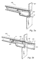
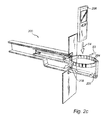
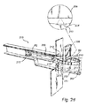
- Figs 2a-d show four different positions of a gripping device according to a currently preferred embodiment of the present invention.
- Fig. 3 illustrates a sensor arrangement and a simplified wiring diagram.
- Fig. 4 illustrates a gripping means according to an alternative embodiment of the present invention.
- Fig. 1 illustrates steps of the method according to a currently preferred embodiment of the present invention.
- step S1 the gripping device is activated for use.
- the activation preferably occurs electronically and can be performed via a sensor, a push button or, for example, using voice activation.
- step S2 a support structure is withdrawn from a bracket, in which the gripping device is arranged, to an outer position by withdrawing a displacing means.
- a gripping means with an adjustable gripping range is arranged, which gripping means extends as a substantially closed loop, and which gripping means is adapted to receive objects of varying shapes and sizes.
- the gripping means is arranged in a receiving position.
- the gripping means may consist of, for example, a ring-like gripping structure, and the receiving position of the gripping means is in this case defined as the position in which the ring-like gripping structure is substantially circular.
- step S4 an object is inserted into the gripping means by a user.
- a sensor is arranged to detect when the object is substantially received by the gripping means.
- the sensor consists of a light source, for example a diode emitting light, and a light sensor receiving light from the light source.
- step S5 the light ray has been "interrupted", and the displacing means is moved back a short distance, which results in the gripping means being stretched, the displacing means thus adjusting the gripping range, whereby the gripping means grips the object.
- step S6 the user has removed the object from the gripping means so that the light sensor again receives the light emitted from the light source.
- the gripping device can then, which is indicated in step S7, either be returned into the bracket, step S8, or be used again to receive an object according to step S4.
- step S8 takes place in a manner corresponding to step S1 preferably electronically, such as automatically after a predetermined time, via a sensor or a push button, or for instance by a voice command.
- Fig. 2a shows a gripping device 200 which is arranged in a bracket 201 according to a currently preferred embodiment of the present invention.
- the gripping device 200 is completely inserted in the bracket 201.
- the gripping device 200 further comprises a sensor 202 which can be used to activate the gripping device 200 to allow it to be used.
- a person with knowledge within the technical field realises that other activating means can be used, such as a push button.
- the gripping device 200 is provided with a transceiver which can be used to detect an RFID tag.
- the gripping device 200 can be activated by an object fitted with an RFID tag, for example a beverage bottle fitted with an RFIF tag, being moved close to the gripping device 200.
- Fig. 2b shows the gripping device 200 in the case where it is to be withdrawn from the bracket 201.
- the gripping device 200 comprises a cogwheel 202, a displacing means 203, and a gripping means 204 which in a first attachment F1 is connected to a support structure 205 and in a second attachment F2 connected to the displacing means 203, which preferably is arranged as a rack.
- the gripping device 200 is withdrawn from the bracket 201 by a "forward" force (indicated by arrow P1) being supplied to the cogwheel 202, which is connected to an electric motor (shown as 302 in Fig. 3).
- Fig. 2c shows the gripping device in the position where it is arranged to receive an object 206.
- the gripping means 204 has in this case been expanded so as to be of a substantially circular shape.
- Fig. 2c also shows a light source 207 emitting light which is received by the light sensor 208.
- the light source 207 in combination with the light sensor 208 constitutes a light ray sensor arrangement, which in the present embodiment is used to detect whether an object 206 is substantially received by the gripping means 204 (detects if the light ray is interrupted).
- Fig. 2d finally shows the position where the object 206 has been received against a receiving surface 209, and the gripping means 204 grips the object 206.
- the light ray that was previously emitted by the light source 207 and received by the light sensor 208 has now been interrupted, and a "backward" force is supplied to the cogwheel 202, which results in the displacing means 203 being returned (which is indicated by arrow P2).
- This causes the gripping means 204 to be stretched, which results in a clamping force acting on the object 206.
- the gripping means 204 further comprises six sensors 210-215.
- the sensors 210-215 are arranged in the gripping means 204, and adapted to detect the object 206.
- the sensors 210-215 are further adjusted to supply object related information to a control unit (shown as 301 in Fig. 3), so that the gripping range of the gripping means 204 is adjusted, whereby the object 206 is fixed in the gripping means 204 (that is the motor is stopped).
- a control unit shown as 301 in Fig. 3
- FIG. 2d An enlarged part of Fig. 2d shows one sensor 210 of the sensors 210-215, which in a preferred embodiment is a reflection sensor.
- a reflection sensor consists of a transmitter and a receiver. The transmitter sends a light ray which is reflected by the object 206. When the object 206 is at a predetermined distance, the reflected light ray hits the receiver, and the reflection sensor communicates that an object has been detected. In a preferred embodiment, the predetermined distance is about 1 mm.
- two opposite sensors have to be activated for the motor to be stopped.
- the output signals from the sensors 210 and 211 are connected to the inputs of the and grid 300, which supplies a detection signal to the control unit 304 only when the two sensors 210 and 211 detect an object 206, such that the motor 302 stops.
- FIG. 4 An alternative embodiment of a gripping means 401 is shown in Fig. 4.
- the gripping means 401 is a rectangular structure.
- the gripping means comprises in this case only four sensors 402-405.
- the gripping device may further comprise means for detecting the type of object that is gripped and adjust the grip thereto.
- the displacing means could be displaced so that the first and the second attachment of the gripping means practically meet, in which case a compressive force will instead act on an object received by the gripping means.
- the advantage of this embodiment is that the gripping means will be able to receive objects of a flat and comparatively wide type, and that a flat side of the object can be oriented towards the passenger compartment so that the driver and/or a passenger can view this flat side.
Landscapes
- Engineering & Computer Science (AREA)
- Mechanical Engineering (AREA)
- Physics & Mathematics (AREA)
- Thermal Sciences (AREA)
- Transportation (AREA)
- Manipulator (AREA)
- Toys (AREA)
Abstract
Description
- The present invention relates to a gripping device which is arranged in a bracket. Moreover the present invention relates to a method of providing a gripping device.
- In modern vehicles, such as cars, boats and airplanes, various types of cup holder are currently available on the market, which are intended to be mounted in the dashboard of the vehicle or in a central bracket arranged in the vehicle. Cup holders of this type are usually adapted to receive a beverage container, such as a mug, a can or a bottle.
- It is very common for the cup holder to consist of a depression which is mainly circular in cross-section and which is adapted to allow the container to be easily inserted and accessed. With this type of adaption, the container is in most cases loosely arranged in the cup holder, which allows the container to move sideways or up and down as the vehicle moves. This is particularly obvious as the vehicle accelerates, when changing the direction or speed of the vehicle, or when the vehicle is driven on an uneven roadway. In any of these situations, the container may easily fall out of the cup holder, which makes it possible for the beverage in the beverage container to leak out into the passenger compartment or splash onto a passenger. This type of leakage may cause stains on the passenger's clothes, the upholstery and/or other interior fittings in the vehicle. Also, if the beverage is hot, a direct contact with a passenger's skin may cause great discomfort.
- A solution to this problem is presented in
US20050082455 , where the cup holder is provided with a circular elastic ring with an opening at the top which is arranged to have a diameter which is less than 90% of the diameter of a standard size beverage container. When inserting the beverage container in the elastic ring, the ring is stretched outwards and encloses the beverage container so that it will be kept in place. A drawback of this device is, however, that it is not adapted to receive other objects than precisely circular objects, such as mugs, cans and bottles, and it is thus not suitable to place, for example, a mobile phone in the cup holder. - It will thus be appreciated that along with the development of, for instance, mobile phones, MP3 players and PDAs there is a need for a more general holder, such as a gripping device, which is adapted to receive objects of varying shapes and sizes.
- The object of the present invention is to provide a device and a method, which eliminates at least one of the above problems. These and other objects are achieved by a gripping device and a method of providing a gripping device as claimed in
claims - According to a first aspect of the invention, a gripping device arranged in a bracket is provided, said gripping device comprising a gripping means with an adjustable gripping range, said gripping means extending as a substantially closed loop, and said gripping means being adapted to receive objects of varying shapes and sizes, a support structure, and a displacing means which is adapted to displace the structure relative to the bracket, and to adjust said gripping range by changing a distance between a first attachment on the gripping means, which is arranged adjacent the support structure, and a second attachment on the gripping means, which is arranged adjacent the displacing means.
- By the expression "closed loop" is here meant according to the present invention that the gripping means is thus arranged to consist of a substantially ring-like structure, whose inner circumference defines the gripping range of the gripping means. The gripping means can advantageously be made of a flexible material, such as rubber or a flexible plastic mixture. Furthermore, the gripping means may, of course, also consist of a number of components which together form the closed loop, for example a number of interconnected rigid portions. It will be appreciated that the gripping means can be formed according to other structural patterns, such as a substantially rectangular structure. The support structure mentioned in the invention is used to support and/or carry the gripping means. The support structure is suitably arranged so that it constitutes a support under the object that is received by the gripping means, but it may also be arranged, for example, at the side of the gripping means, without departing from the inventive concept. The support structure is preferably made of a light and strong material, such as plastic or metal, but it will be appreciated that other types of material can be used.
- The displacing means consists, for example, of an elongated rack which is connected to an electrically controlled motor, or an electrically controlled telescopic device (with a displacing function similar to for example an electric antenna).
- As described above, the gripping means comprises a first and a second attachment, which for example may consist of a first and a second fixing point, which are arranged adjacent the support structure and the displacing means, respectively. By adjusting the distance between these two attachments, a change of a clamping force is achieved, which acts on an object received in the gripping means. If, for example, the distance is increased between the two attachments, the gripping means will be stretched, which results in a more elongated shape of the gripping means, and an increase of the clamping force which acts on the object received in the gripping means. On the other hand, the clamping force which acts on the object received in the gripping means is reduced if the distance between the two attachments is reduced as the gripping means returns to an initial receiving position.
- To increase the flexibility of the gripping means, the attachments of the gripping means are preferably movably and/or rotatably arranged. For maximum clamping force, the second attachment is usually arranged substantially opposite the first attachment.
- With a gripping device according to the present invention, it will be possible to hold different types of objects, which have different sizes and shapes, such as a mug, a bottle, a mobile phone, an MP3 player, a pen, a credit card or a thin-walled plastic mug. The only restriction placed on the object to be received by the gripping means is that there should be room enough within the gripping range of the gripping means. The gripping range of the gripping means can, which is understood by a person skilled in the art, be adjusted to suit the space in which the gripping device is arranged and the type of object that the gripping means is expected to hold.
- In a preferred embodiment, the gripping device comprises at least one control unit, which control unit is at least adapted to control said displacing means, and sensors, which sensors are at least arranged in said gripping means, adapted to detect said object which is received by said gripping means, and adapted to supply object-related information to said control unit so that said gripping range can be adjusted, whereby said object is fixed in said gripping means. By object-related information is here meant, for example, the presence of an object, the distance to an object, the structural properties and nature of the object.
- By arranging sensors in the gripping means and arranging them to communicate with the control unit which controls the gripping means, the gripping range of the gripping means can be adjusted so that the object received in the gripping means is sufficiently gripped. A sufficient grip combined with a gripping means which is made of an elastic material as mentioned above makes it possible for the object to be fixed in a favourable manner independently of its shape or size. The gripping means may further comprise at least one sensor to activate the gripping means. This sensor prevents the actual adjustment of the gripping range from being begun before the object is properly received in the gripping means. Both the latter sensor and the above-mentioned sensors arranged in the gripping means may consist of, for example, light sensors, pressure sensors, acoustic sensors, light ray sensors and/or motion sensors. In a vehicle application, it is currently preferred to use light sensors since they involve low cost. Furthermore the control unit may, of course, constitute part of a central computer system, but can, as will be understood by a person skilled in the art, also be a control unit which is particularly adapted to the present objects of the invention, such as a microprocessor or the like.
- In a particularly preferred embodiment of the present invention, the bracket consists of one of a dashboard in a vehicle and a central bracket in a vehicle. By a vehicle is preferably meant a passenger car, a truck, a bus, a boat, a train and an airplane, but it will be appreciated that other fields of application are conceivable, and that the gripping device according to the present invention can be arranged in other positions in the vehicle.
- For maximum flexibility, the gripping device can be adapted to be electronically activated, such as by means of a sensor or a push button. Other electronic activation options are also available, such as, for example, voice activation and motion activation. By activating the gripping device by, for instance, the user's voice, it will be possible for him to activate the gripping device without using his hand.
- According to a second aspect, the invention concerns a method of providing a gripping device, comprising the steps of withdrawing a support structure from a bracket to an outer position by withdrawing a displacing means, adjacent to said support structure there being arranged a first attachment on a gripping means with an adjustable gripping range, said gripping means extending as a substantially closed loop, and said gripping means being adapted to receive objects of varying shapes and sizes, arranging the gripping means in a receiving position, detecting the presence of an object which is received by the gripping means, and returning said displacing means, adjacent to said displacing means there being arranged a second attachment on said gripping means, thereby reducing said gripping range.
- As described above with reference to the first aspect of the present invention, this method presents the option of gripping various types of objects, which have different sizes and shapes, such as a mug, a bottle, a mobile phone or an MP3 player.
- Additional features and advantages of the present invention, as well as the construction and function of various embodiments of the present invention, will be described below in detail with reference to the accompanying drawings.
- The accompanying drawings, which are part of the description, illustrate currently preferred embodiments of the present invention and are adapted to explain, together with the description, the principles of the invention, and to make it possible for a person with knowledge within the technical field involved to use the invention. In the drawings, like reference numerals concern identical or functionally similar components.
- Fig. 1 is a block diagram of the steps of the method according to the present invention.
- Figs 2a-d show four different positions of a gripping device according to a currently preferred embodiment of the present invention.
- Fig. 3 illustrates a sensor arrangement and a simplified wiring diagram.
- Fig. 4 illustrates a gripping means according to an alternative embodiment of the present invention.
- Fig. 1 illustrates steps of the method according to a currently preferred embodiment of the present invention.
- In step S1, the gripping device is activated for use. The activation preferably occurs electronically and can be performed via a sensor, a push button or, for example, using voice activation.
- In step S2, a support structure is withdrawn from a bracket, in which the gripping device is arranged, to an outer position by withdrawing a displacing means. Between a first attachment on the support structure and a second attachment on the displacing means, a gripping means with an adjustable gripping range is arranged, which gripping means extends as a substantially closed loop, and which gripping means is adapted to receive objects of varying shapes and sizes.
- In step S3, the gripping means is arranged in a receiving position. The gripping means may consist of, for example, a ring-like gripping structure, and the receiving position of the gripping means is in this case defined as the position in which the ring-like gripping structure is substantially circular.
- In step S4, an object is inserted into the gripping means by a user. A sensor is arranged to detect when the object is substantially received by the gripping means. In one embodiment, the sensor consists of a light source, for example a diode emitting light, and a light sensor receiving light from the light source.
- In step S5, the light ray has been "interrupted", and the displacing means is moved back a short distance, which results in the gripping means being stretched, the displacing means thus adjusting the gripping range, whereby the gripping means grips the object.
- In step S6, the user has removed the object from the gripping means so that the light sensor again receives the light emitted from the light source.
- The gripping device can then, which is indicated in step S7, either be returned into the bracket, step S8, or be used again to receive an object according to step S4.
- The return of the gripping device, step S8, takes place in a manner corresponding to step S1 preferably electronically, such as automatically after a predetermined time, via a sensor or a push button, or for instance by a voice command.
- The method steps S1 to S5 above will now be described in more detail with reference to Figs 2a-2d.
- Fig. 2a shows a
gripping device 200 which is arranged in abracket 201 according to a currently preferred embodiment of the present invention. In this case thegripping device 200 is completely inserted in thebracket 201. Thegripping device 200 further comprises asensor 202 which can be used to activate thegripping device 200 to allow it to be used. A person with knowledge within the technical field realises that other activating means can be used, such as a push button. In an alternative embodiment, thegripping device 200 is provided with a transceiver which can be used to detect an RFID tag. In this case thegripping device 200 can be activated by an object fitted with an RFID tag, for example a beverage bottle fitted with an RFIF tag, being moved close to thegripping device 200. - Fig. 2b shows the
gripping device 200 in the case where it is to be withdrawn from thebracket 201. Thegripping device 200 comprises acogwheel 202, a displacing means 203, and agripping means 204 which in a first attachment F1 is connected to asupport structure 205 and in a second attachment F2 connected to the displacing means 203, which preferably is arranged as a rack. Thegripping device 200 is withdrawn from thebracket 201 by a "forward" force (indicated by arrow P1) being supplied to thecogwheel 202, which is connected to an electric motor (shown as 302 in Fig. 3). - Fig. 2c shows the gripping device in the position where it is arranged to receive an
object 206. The gripping means 204 has in this case been expanded so as to be of a substantially circular shape. Fig. 2c also shows alight source 207 emitting light which is received by thelight sensor 208. Thelight source 207 in combination with thelight sensor 208 constitutes a light ray sensor arrangement, which in the present embodiment is used to detect whether anobject 206 is substantially received by the gripping means 204 (detects if the light ray is interrupted). - Fig. 2d finally shows the position where the
object 206 has been received against a receivingsurface 209, and the gripping means 204 grips theobject 206. The light ray that was previously emitted by thelight source 207 and received by thelight sensor 208 has now been interrupted, and a "backward" force is supplied to thecogwheel 202, which results in the displacing means 203 being returned (which is indicated by arrow P2). This, in turn, causes the gripping means 204 to be stretched, which results in a clamping force acting on theobject 206. The gripping means 204 further comprises six sensors 210-215. The sensors 210-215 are arranged in the gripping means 204, and adapted to detect theobject 206. The sensors 210-215 are further adjusted to supply object related information to a control unit (shown as 301 in Fig. 3), so that the gripping range of the gripping means 204 is adjusted, whereby theobject 206 is fixed in the gripping means 204 (that is the motor is stopped). - An enlarged part of Fig. 2d shows one
sensor 210 of the sensors 210-215, which in a preferred embodiment is a reflection sensor. A reflection sensor consists of a transmitter and a receiver. The transmitter sends a light ray which is reflected by theobject 206. When theobject 206 is at a predetermined distance, the reflected light ray hits the receiver, and the reflection sensor communicates that an object has been detected. In a preferred embodiment, the predetermined distance is about 1 mm. - In a preferred embodiment, two opposite sensors have to be activated for the motor to be stopped. This is shown in Fig. 3, in which two
sensors sensors grid 300, which supplies a detection signal to the control unit 304 only when the twosensors object 206, such that themotor 302 stops. - An alternative embodiment of a
gripping means 401 is shown in Fig. 4. In this case, the gripping means 401 is a rectangular structure. The gripping means comprises in this case only four sensors 402-405. - Finally, it should be added that the invention is in no way limited to the described embodiment. For example, the gripping device according to the present invention may further comprise means for detecting the type of object that is gripped and adjust the grip thereto. In a special case, the displacing means could be displaced so that the first and the second attachment of the gripping means practically meet, in which case a compressive force will instead act on an object received by the gripping means. The advantage of this embodiment is that the gripping means will be able to receive objects of a flat and comparatively wide type, and that a flat side of the object can be oriented towards the passenger compartment so that the driver and/or a passenger can view this flat side.
Claims (12)
- A gripping device (200) arranged in a bracket (201), said gripping device (200) comprising:- a gripping means (204) with an adjustable gripping range, said gripping means (204) extending as a substantially closed loop, and said gripping means (204) being adapted to receive objects (206) of varying shapes and sizes,- a support structure (205), and- a displacing means (203) which is adapted to:- displace said support structure (205) relative to said bracket (201), and- adjust said gripping range by changing a distance between a first attachment (F1) on said gripping means (204), which first attachment (F1) is arranged adjacent said support structure (205), and a second attachment (F2) on said gripping means (204), which second attachment (F2) is arranged adjacent said displacing means (203).
- A gripping device (200) as claimed in claim 1, which further comprises:- at least one control unit (301), which control unit (301) is at least adapted to control said displacing means (203), and- sensors (210-215), which sensors (210-215) are at least:- arranged in said gripping means (204),- adapted to detect said object (206) which is received by said gripping means (204), and- adapted to supply object-related information to said control unit (301) so that said gripping range can be adjusted, whereby said object (206) is fixed in said gripping means (204).
- A gripping device (200) as claimed in any one of the preceding claims, wherein said gripping device (200) further comprises at least one sensor (207, 208) to activate said gripping means (204).
- A gripping device (200) as claimed in any one of the preceding claims, wherein said bracket (201) is one of a dashboard in a vehicle and a central bracket in a vehicle.
- A gripping device (200) as claimed in any one of the preceding claims, wherein said gripping device (200) is electronically activated.
- A gripping device (200) as claimed in claim 5, wherein said gripping device (200) is activated by at least one of voice activation, motion activation, a sensor (202), a push button.
- A gripping device (200) as claimed in any one of claims 2-6, wherein said sensors (202, 207, 208, 210-215) are selected from a group of sensors comprising light sensors, pressure sensors, acoustic sensors, motion sensors, light ray sensors.
- A method of providing a gripping device (200), comprising the steps of:- withdrawing a support structure (205) from a bracket (201) to an outer position by withdrawing a displacing means (203), adjacent to said support structure (205) there being arranged a first attachment (F1) on a gripping means (204) with an adjustable gripping range, said gripping means (204) extending as a substantially closed loop, and said gripping means (204) being adapted to receive objects (206) of varying shapes and sizes,- arranging the gripping means (204) in a receiving position,- detecting the presence of an object (206) which is received by the gripping means (204), and- returning said displacing means (203), adjacent to said displacing means (203) there being arranged a second attachment (F2) on said gripping means (204), thereby reducing said gripping range.
- A method as claimed in claim 8, further comprising the step of returning said support structure (205) into said bracket (201).
- A method as claimed in claims 8-9, further comprising the step of electronically activating said gripping device (200).
- A method as claimed in claim 10, wherein said gripping device (200) is activated by at least one of voice activation, motion activation, a sensor (202), a push button.
- A method as claimed in claims 8-11, further comprising the steps of- collecting object-related information about an object received in said gripping means (204) from sensors (210-215) which are arranged in said gripping means (204), and- adjusting said gripping range by said object related information.
Applications Claiming Priority (1)
| Application Number | Priority Date | Filing Date | Title |
|---|---|---|---|
| SE0502925A SE531042C2 (en) | 2005-12-29 | 2005-12-29 | Grips and method for providing a gripper |
Publications (2)
| Publication Number | Publication Date |
|---|---|
| EP1803608A1 true EP1803608A1 (en) | 2007-07-04 |
| EP1803608B1 EP1803608B1 (en) | 2010-01-27 |
Family
ID=37735277
Family Applications (1)
| Application Number | Title | Priority Date | Filing Date |
|---|---|---|---|
| EP06126711A Not-in-force EP1803608B1 (en) | 2005-12-29 | 2006-12-20 | Gripping Device and Method of Providing a Gripping Device |
Country Status (6)
| Country | Link |
|---|---|
| US (1) | US7648114B2 (en) |
| EP (1) | EP1803608B1 (en) |
| CN (1) | CN1990307A (en) |
| AT (1) | ATE456489T1 (en) |
| DE (1) | DE602006012008D1 (en) |
| SE (1) | SE531042C2 (en) |
Cited By (8)
| Publication number | Priority date | Publication date | Assignee | Title |
|---|---|---|---|---|
| FR2920118A1 (en) * | 2007-08-24 | 2009-02-27 | Renault Sas | A BEVERAGE RECEPTACLE FOR RECEIVING A PORTABLE TELEPHONE |
| FR2932442A1 (en) * | 2008-06-17 | 2009-12-18 | Faurecia Interieur Ind | Portable article e.g. portable telephone, supporting device for motor vehicle, has maintaining units for maintaining article on support, where units comprise lateral maintaining elements adjustable according to width of article |
| WO2010127260A1 (en) * | 2009-04-30 | 2010-11-04 | Corry Charles D | Universal ear-bud holder |
| DE102009033878A1 (en) | 2009-07-17 | 2011-01-27 | Audi Ag | Device for removable holding of e.g. flat article in receptacle container of motor vehicle, has clamping elements spring-tensioned to support article with different diameters, where surfaces of elements are aligned in radial direction |
| EP2546105A1 (en) * | 2011-07-14 | 2013-01-16 | LG Electronics Inc. | Holding apparatus for portable electronic device |
| WO2018234271A1 (en) * | 2017-06-23 | 2018-12-27 | Audi Ag | DEVICE FOR A MOTOR VEHICLE, METHOD FOR OPERATING A DEVICE, CONTROL DEVICE AND MOTOR VEHICLE |
| CN111655543A (en) * | 2018-01-23 | 2020-09-11 | 博泽科堡汽车零件欧洲两合公司 | Storage box assembly with force actuated wall element and swingable bottom element |
| GB2566599B (en) * | 2017-07-27 | 2021-12-22 | Medline Ind Inc | Dual receptacle carrier |
Families Citing this family (21)
| Publication number | Priority date | Publication date | Assignee | Title |
|---|---|---|---|---|
| KR100809047B1 (en) * | 2007-03-20 | 2008-03-03 | 류희석 | Dashboard with portable terminal compartment |
| US7784843B2 (en) * | 2008-01-08 | 2010-08-31 | Toyota Motor Engineering & Manufacturing North America, Inc. | Vehicle console with sliding panel |
| US8172293B2 (en) * | 2008-01-09 | 2012-05-08 | Toyota Motor Engineering & Manufacturing North America, Inc. | Vehicle electronic device support systems |
| JP5359046B2 (en) * | 2008-06-19 | 2013-12-04 | 富士通株式会社 | Terminal apparatus and method |
| CN103295051B (en) * | 2012-02-29 | 2016-04-06 | 国际商业机器公司 | Electronic tag clamping device |
| JP5541430B1 (en) * | 2013-08-19 | 2014-07-09 | ソニー株式会社 | Imaging unit, mounting device |
| US20150158589A1 (en) * | 2013-12-05 | 2015-06-11 | Intertechnique | Tray Table Unit For An Aircraft |
| US9637078B2 (en) * | 2014-11-14 | 2017-05-02 | Nxp Usa, Inc. | Object restraint systems and methods of operation thereof |
| DE102015100972B4 (en) * | 2015-01-23 | 2025-01-02 | Dr. Ing. H.C. F. Porsche Aktiengesellschaft | vessel holding device for a motor vehicle |
| CN105501095B (en) * | 2015-11-19 | 2017-12-01 | 重庆市木越机械制造有限公司 | Device for the holding cup on automobile |
| CN105291930B (en) * | 2015-11-19 | 2017-09-29 | 蔡姝婕 | Cup apparatus for placing on automobile |
| CN105291931B (en) * | 2015-11-19 | 2017-10-10 | 姜天 | It is a kind of to be used for the device of the holding cup on vehicle |
| CN105216675B (en) * | 2015-11-19 | 2017-12-05 | 重庆市木越机械制造有限公司 | A kind of device for being used for the holding cup on automobile |
| CN105329136B (en) * | 2015-11-19 | 2017-09-29 | 姜天 | Device for the holding cup on vehicle |
| US10046710B2 (en) | 2016-03-16 | 2018-08-14 | Ford Global Technologies, Llc | Versatile article retainer assembly for a motor vehicle |
| CN107720659B (en) * | 2016-08-10 | 2020-04-03 | 奥迪股份公司 | Bottle opening and closing device for use in motor vehicles |
| US9969312B2 (en) * | 2016-09-21 | 2018-05-15 | Honda Motor Co., Ltd. | Container holder for motor vehicle |
| CN108725332B (en) * | 2017-04-19 | 2023-06-02 | 福特环球技术公司 | Device holder mountable on A-pillar |
| DE102019002862A1 (en) * | 2019-04-17 | 2020-10-22 | Daimler Ag | Method for operating a storage system of a motor vehicle for a product and storage system |
| CN110386047B (en) * | 2019-08-20 | 2024-05-17 | 宁波帅特龙集团有限公司 | Automatic folding telescopic cup stand for vehicle |
| US12036907B2 (en) * | 2022-09-12 | 2024-07-16 | Kenneth Kamman | Voice and manually powered retractable automobile cup holder |
Citations (5)
| Publication number | Priority date | Publication date | Assignee | Title |
|---|---|---|---|---|
| US4728018A (en) * | 1987-06-15 | 1988-03-01 | General Motors Corporation | Beverage holder for vehicle |
| EP0633162A1 (en) * | 1993-07-08 | 1995-01-11 | Manchester Plastics | Powered cup holder |
| DE19755621A1 (en) * | 1997-12-13 | 1999-06-17 | Mannesmann Vdo Ag | Retainer for mobile telephone in car |
| EP1033282A2 (en) * | 1999-03-02 | 2000-09-06 | fischerwerke Artur Fischer GmbH & Co. KG | Holder for beverage receptacle in an automotive vehicle |
| US20020008127A1 (en) | 2000-07-14 | 2002-01-24 | Glovatsky Andrew Zachary | Container holder that utilizes moldline structures |
Family Cites Families (10)
| Publication number | Priority date | Publication date | Assignee | Title |
|---|---|---|---|---|
| US4645157A (en) | 1985-12-23 | 1987-02-24 | General Motors Corporation | Beverage holder for vehicle |
| US4783037A (en) | 1987-08-10 | 1988-11-08 | Prince Corporation | Container holder for a vehicle |
| US5704579A (en) | 1996-08-26 | 1998-01-06 | Ford Global Technologies, Inc. | Drink container holder usable especially in automotive vehicles |
| US5839710A (en) * | 1997-05-05 | 1998-11-24 | Ford Global Technologies, Inc. | Concealable variable size vehicle container holder with flexible band |
| DE19847609A1 (en) | 1998-10-15 | 2000-04-20 | Volkswagen Ag | Device for holding everyday objects in vehicles, in particular motor vehicles |
| DE29822972U1 (en) * | 1998-12-28 | 1999-03-04 | Sarnatech Paulmann & Crone GmbH, 58509 Lüdenscheid | Device for holding beverage containers in motor vehicles |
| DE19921599A1 (en) | 1999-05-07 | 2000-11-09 | Riesselmann F & H Kunststoff | Holding device for vessels in motor vehicles |
| CA2324614A1 (en) | 2000-02-28 | 2001-08-28 | Volvo Trucks Of North America, Inc. | Vehicle cupholder |
| DE10121115A1 (en) * | 2001-04-28 | 2002-10-31 | Leica Microsystems | Holding device for wafers |
| DE10253405A1 (en) | 2001-11-22 | 2003-06-18 | Nifco Inc | extracting device |
-
2005
- 2005-12-29 SE SE0502925A patent/SE531042C2/en not_active IP Right Cessation
-
2006
- 2006-12-20 DE DE602006012008T patent/DE602006012008D1/en active Active
- 2006-12-20 EP EP06126711A patent/EP1803608B1/en not_active Not-in-force
- 2006-12-20 AT AT06126711T patent/ATE456489T1/en not_active IP Right Cessation
- 2006-12-22 US US11/643,703 patent/US7648114B2/en not_active Expired - Fee Related
- 2006-12-28 CN CNA2006101682427A patent/CN1990307A/en active Pending
Patent Citations (5)
| Publication number | Priority date | Publication date | Assignee | Title |
|---|---|---|---|---|
| US4728018A (en) * | 1987-06-15 | 1988-03-01 | General Motors Corporation | Beverage holder for vehicle |
| EP0633162A1 (en) * | 1993-07-08 | 1995-01-11 | Manchester Plastics | Powered cup holder |
| DE19755621A1 (en) * | 1997-12-13 | 1999-06-17 | Mannesmann Vdo Ag | Retainer for mobile telephone in car |
| EP1033282A2 (en) * | 1999-03-02 | 2000-09-06 | fischerwerke Artur Fischer GmbH & Co. KG | Holder for beverage receptacle in an automotive vehicle |
| US20020008127A1 (en) | 2000-07-14 | 2002-01-24 | Glovatsky Andrew Zachary | Container holder that utilizes moldline structures |
Cited By (18)
| Publication number | Priority date | Publication date | Assignee | Title |
|---|---|---|---|---|
| WO2009027608A1 (en) * | 2007-08-24 | 2009-03-05 | Renault S.A.S. | Beverage receptacle capable of receiving a mobile phone |
| FR2920118A1 (en) * | 2007-08-24 | 2009-02-27 | Renault Sas | A BEVERAGE RECEPTACLE FOR RECEIVING A PORTABLE TELEPHONE |
| FR2932442A1 (en) * | 2008-06-17 | 2009-12-18 | Faurecia Interieur Ind | Portable article e.g. portable telephone, supporting device for motor vehicle, has maintaining units for maintaining article on support, where units comprise lateral maintaining elements adjustable according to width of article |
| US8403135B2 (en) | 2009-04-30 | 2013-03-26 | Charles D. CORRY | Universal ear-bud holder |
| WO2010127260A1 (en) * | 2009-04-30 | 2010-11-04 | Corry Charles D | Universal ear-bud holder |
| DE102009033878B4 (en) * | 2009-07-17 | 2016-06-09 | Audi Ag | Holding device for releasably holding objects in a receptacle |
| DE102009033878A1 (en) | 2009-07-17 | 2011-01-27 | Audi Ag | Device for removable holding of e.g. flat article in receptacle container of motor vehicle, has clamping elements spring-tensioned to support article with different diameters, where surfaces of elements are aligned in radial direction |
| EP2546105A1 (en) * | 2011-07-14 | 2013-01-16 | LG Electronics Inc. | Holding apparatus for portable electronic device |
| US9014393B2 (en) | 2011-07-14 | 2015-04-21 | Lg Electronics Inc. | Stationary apparatus for portable electronic device |
| WO2018234271A1 (en) * | 2017-06-23 | 2018-12-27 | Audi Ag | DEVICE FOR A MOTOR VEHICLE, METHOD FOR OPERATING A DEVICE, CONTROL DEVICE AND MOTOR VEHICLE |
| CN110869243A (en) * | 2017-06-23 | 2020-03-06 | 奥迪股份公司 | Storage device for motor vehicle, method for operating storage device, control device and motor vehicle |
| DE102017210640B4 (en) | 2017-06-23 | 2021-12-30 | Audi Ag | Storage device for a motor vehicle, method for operating a storage device, control device and motor vehicle |
| US11351902B2 (en) | 2017-06-23 | 2022-06-07 | Audi Ag | Holding device for use in a motor vehicle, method for operating a holding device, control unit and motor vehicle |
| GB2566599B (en) * | 2017-07-27 | 2021-12-22 | Medline Ind Inc | Dual receptacle carrier |
| US11364171B2 (en) | 2017-07-27 | 2022-06-21 | Medline Industries, Lp | Dual receptacle carrier |
| CN111655543A (en) * | 2018-01-23 | 2020-09-11 | 博泽科堡汽车零件欧洲两合公司 | Storage box assembly with force actuated wall element and swingable bottom element |
| KR20200108468A (en) * | 2018-01-23 | 2020-09-18 | 브로제 파르쪼이크타일레 에스이 운트 코. 콤만디트게젤샤프트, 코부르크 | Loading compartment assembly with external force actuated wall elements and pivotable floor elements |
| JP2021511256A (en) * | 2018-01-23 | 2021-05-06 | ブローズ ファールツォイクタイレ エスエー ウント シーオー. カーゲー, コブルクBrose Fahrzeugteile Se & Co. Kg, Coburg | Storage compartment assembly with externally actuated wall elements and rotatable base elements |
Also Published As
| Publication number | Publication date |
|---|---|
| US7648114B2 (en) | 2010-01-19 |
| ATE456489T1 (en) | 2010-02-15 |
| DE602006012008D1 (en) | 2010-03-18 |
| EP1803608B1 (en) | 2010-01-27 |
| SE531042C2 (en) | 2008-11-25 |
| SE0502925L (en) | 2007-06-30 |
| CN1990307A (en) | 2007-07-04 |
| US20070170332A1 (en) | 2007-07-26 |
Similar Documents
| Publication | Publication Date | Title |
|---|---|---|
| EP1803608B1 (en) | Gripping Device and Method of Providing a Gripping Device | |
| US9690729B2 (en) | Tablet computer dock | |
| US9981589B2 (en) | Vehicular console box | |
| US10850656B2 (en) | Apparatus including inductive charger and retractable cup holder | |
| US20070176449A1 (en) | Holder for an electronic device | |
| US20050205739A1 (en) | Cup holder with sensor | |
| US9823349B2 (en) | Driver entry detector for a motor vehicle | |
| US9283876B2 (en) | Head restraint with storage | |
| KR20160130481A (en) | Vehicle having a driver assistance device | |
| US7036700B2 (en) | Multi-purpose holder installed in a vehicle | |
| CN115352324A (en) | Vehicle with sliding console | |
| CN101011945B (en) | An instrument panel for a motor vehicle | |
| GB2453110A (en) | Magnetic storage system | |
| CN214396528U (en) | Vehicle-mounted cup stand and vehicle | |
| GB2585458A (en) | Multi-functional receptacle holder | |
| US20200307477A1 (en) | Vehicle seating adjustment system | |
| EP3263400B1 (en) | Cup holder releasably mountable on an armrest of a vehicle | |
| US20090244917A1 (en) | Automotive interior component combining light and movement | |
| CN215398346U (en) | Automobile cup holder | |
| KR100806356B1 (en) | Cup holder and method for controlling the same | |
| CN112389335A (en) | Control panel element for installation in a motor vehicle | |
| CN121224584A (en) | A system for holding items | |
| US6776381B1 (en) | Cup holder | |
| CN215244500U (en) | Cup holder and have its vice instrument board and vehicle | |
| US11065997B2 (en) | Motor vehicle |
Legal Events
| Date | Code | Title | Description |
|---|---|---|---|
| PUAI | Public reference made under article 153(3) epc to a published international application that has entered the european phase |
Free format text: ORIGINAL CODE: 0009012 |
|
| AK | Designated contracting states |
Kind code of ref document: A1 Designated state(s): AT BE BG CH CY CZ DE DK EE ES FI FR GB GR HU IE IS IT LI LT LU LV MC NL PL PT RO SE SI SK TR |
|
| AX | Request for extension of the european patent |
Extension state: AL BA HR MK YU |
|
| 17P | Request for examination filed |
Effective date: 20071205 |
|
| 17Q | First examination report despatched |
Effective date: 20080121 |
|
| AKX | Designation fees paid |
Designated state(s): AT BE BG CH CY CZ DE DK EE ES FI FR GB GR HU IE IS IT LI LT LU LV MC NL PL PT RO SE SI SK TR |
|
| GRAP | Despatch of communication of intention to grant a patent |
Free format text: ORIGINAL CODE: EPIDOSNIGR1 |
|
| GRAS | Grant fee paid |
Free format text: ORIGINAL CODE: EPIDOSNIGR3 |
|
| GRAA | (expected) grant |
Free format text: ORIGINAL CODE: 0009210 |
|
| AK | Designated contracting states |
Kind code of ref document: B1 Designated state(s): AT BE BG CH CY CZ DE DK EE ES FI FR GB GR HU IE IS IT LI LT LU LV MC NL PL PT RO SE SI SK TR |
|
| REG | Reference to a national code |
Ref country code: GB Ref legal event code: FG4D |
|
| REG | Reference to a national code |
Ref country code: CH Ref legal event code: EP |
|
| REG | Reference to a national code |
Ref country code: IE Ref legal event code: FG4D |
|
| REF | Corresponds to: |
Ref document number: 602006012008 Country of ref document: DE Date of ref document: 20100318 Kind code of ref document: P |
|
| REG | Reference to a national code |
Ref country code: NL Ref legal event code: VDEP Effective date: 20100127 |
|
| LTIE | Lt: invalidation of european patent or patent extension |
Effective date: 20100127 |
|
| PG25 | Lapsed in a contracting state [announced via postgrant information from national office to epo] |
Ref country code: AT Free format text: LAPSE BECAUSE OF FAILURE TO SUBMIT A TRANSLATION OF THE DESCRIPTION OR TO PAY THE FEE WITHIN THE PRESCRIBED TIME-LIMIT Effective date: 20100127 |
|
| PG25 | Lapsed in a contracting state [announced via postgrant information from national office to epo] |
Ref country code: IS Free format text: LAPSE BECAUSE OF FAILURE TO SUBMIT A TRANSLATION OF THE DESCRIPTION OR TO PAY THE FEE WITHIN THE PRESCRIBED TIME-LIMIT Effective date: 20100527 Ref country code: PT Free format text: LAPSE BECAUSE OF FAILURE TO SUBMIT A TRANSLATION OF THE DESCRIPTION OR TO PAY THE FEE WITHIN THE PRESCRIBED TIME-LIMIT Effective date: 20100527 Ref country code: NL Free format text: LAPSE BECAUSE OF FAILURE TO SUBMIT A TRANSLATION OF THE DESCRIPTION OR TO PAY THE FEE WITHIN THE PRESCRIBED TIME-LIMIT Effective date: 20100127 Ref country code: ES Free format text: LAPSE BECAUSE OF FAILURE TO SUBMIT A TRANSLATION OF THE DESCRIPTION OR TO PAY THE FEE WITHIN THE PRESCRIBED TIME-LIMIT Effective date: 20100508 Ref country code: LT Free format text: LAPSE BECAUSE OF FAILURE TO SUBMIT A TRANSLATION OF THE DESCRIPTION OR TO PAY THE FEE WITHIN THE PRESCRIBED TIME-LIMIT Effective date: 20100127 |
|
| PG25 | Lapsed in a contracting state [announced via postgrant information from national office to epo] |
Ref country code: PL Free format text: LAPSE BECAUSE OF FAILURE TO SUBMIT A TRANSLATION OF THE DESCRIPTION OR TO PAY THE FEE WITHIN THE PRESCRIBED TIME-LIMIT Effective date: 20100127 Ref country code: SI Free format text: LAPSE BECAUSE OF FAILURE TO SUBMIT A TRANSLATION OF THE DESCRIPTION OR TO PAY THE FEE WITHIN THE PRESCRIBED TIME-LIMIT Effective date: 20100127 Ref country code: LV Free format text: LAPSE BECAUSE OF FAILURE TO SUBMIT A TRANSLATION OF THE DESCRIPTION OR TO PAY THE FEE WITHIN THE PRESCRIBED TIME-LIMIT Effective date: 20100127 Ref country code: FI Free format text: LAPSE BECAUSE OF FAILURE TO SUBMIT A TRANSLATION OF THE DESCRIPTION OR TO PAY THE FEE WITHIN THE PRESCRIBED TIME-LIMIT Effective date: 20100127 |
|
| PG25 | Lapsed in a contracting state [announced via postgrant information from national office to epo] |
Ref country code: GR Free format text: LAPSE BECAUSE OF FAILURE TO SUBMIT A TRANSLATION OF THE DESCRIPTION OR TO PAY THE FEE WITHIN THE PRESCRIBED TIME-LIMIT Effective date: 20100428 Ref country code: EE Free format text: LAPSE BECAUSE OF FAILURE TO SUBMIT A TRANSLATION OF THE DESCRIPTION OR TO PAY THE FEE WITHIN THE PRESCRIBED TIME-LIMIT Effective date: 20100127 Ref country code: CY Free format text: LAPSE BECAUSE OF FAILURE TO SUBMIT A TRANSLATION OF THE DESCRIPTION OR TO PAY THE FEE WITHIN THE PRESCRIBED TIME-LIMIT Effective date: 20100127 Ref country code: BE Free format text: LAPSE BECAUSE OF FAILURE TO SUBMIT A TRANSLATION OF THE DESCRIPTION OR TO PAY THE FEE WITHIN THE PRESCRIBED TIME-LIMIT Effective date: 20100127 Ref country code: SE Free format text: LAPSE BECAUSE OF FAILURE TO SUBMIT A TRANSLATION OF THE DESCRIPTION OR TO PAY THE FEE WITHIN THE PRESCRIBED TIME-LIMIT Effective date: 20100127 Ref country code: RO Free format text: LAPSE BECAUSE OF FAILURE TO SUBMIT A TRANSLATION OF THE DESCRIPTION OR TO PAY THE FEE WITHIN THE PRESCRIBED TIME-LIMIT Effective date: 20100127 |
|
| PG25 | Lapsed in a contracting state [announced via postgrant information from national office to epo] |
Ref country code: CZ Free format text: LAPSE BECAUSE OF FAILURE TO SUBMIT A TRANSLATION OF THE DESCRIPTION OR TO PAY THE FEE WITHIN THE PRESCRIBED TIME-LIMIT Effective date: 20100127 Ref country code: BG Free format text: LAPSE BECAUSE OF FAILURE TO SUBMIT A TRANSLATION OF THE DESCRIPTION OR TO PAY THE FEE WITHIN THE PRESCRIBED TIME-LIMIT Effective date: 20100427 Ref country code: SK Free format text: LAPSE BECAUSE OF FAILURE TO SUBMIT A TRANSLATION OF THE DESCRIPTION OR TO PAY THE FEE WITHIN THE PRESCRIBED TIME-LIMIT Effective date: 20100127 |
|
| PLBE | No opposition filed within time limit |
Free format text: ORIGINAL CODE: 0009261 |
|
| STAA | Information on the status of an ep patent application or granted ep patent |
Free format text: STATUS: NO OPPOSITION FILED WITHIN TIME LIMIT |
|
| 26N | No opposition filed |
Effective date: 20101028 |
|
| PG25 | Lapsed in a contracting state [announced via postgrant information from national office to epo] |
Ref country code: DK Free format text: LAPSE BECAUSE OF FAILURE TO SUBMIT A TRANSLATION OF THE DESCRIPTION OR TO PAY THE FEE WITHIN THE PRESCRIBED TIME-LIMIT Effective date: 20100127 |
|
| PG25 | Lapsed in a contracting state [announced via postgrant information from national office to epo] |
Ref country code: IT Free format text: LAPSE BECAUSE OF FAILURE TO SUBMIT A TRANSLATION OF THE DESCRIPTION OR TO PAY THE FEE WITHIN THE PRESCRIBED TIME-LIMIT Effective date: 20100127 |
|
| REG | Reference to a national code |
Ref country code: DE Ref legal event code: R081 Ref document number: 602006012008 Country of ref document: DE Owner name: GM GLOBAL TECHNOLOGY OPERATIONS LLC (N. D. GES, US Free format text: FORMER OWNER: GM GLOBAL TECHNOLOGY OPERATIONS, INC., DETROIT, US Effective date: 20110323 Ref country code: DE Ref legal event code: R081 Ref document number: 602006012008 Country of ref document: DE Owner name: GM GLOBAL TECHNOLOGY OPERATIONS LLC (N. D. GES, US Free format text: FORMER OWNER: GM GLOBAL TECHNOLOGY OPERATIONS, INC., DETROIT, MICH., US Effective date: 20110323 |
|
| PG25 | Lapsed in a contracting state [announced via postgrant information from national office to epo] |
Ref country code: MC Free format text: LAPSE BECAUSE OF NON-PAYMENT OF DUE FEES Effective date: 20101231 |
|
| REG | Reference to a national code |
Ref country code: CH Ref legal event code: PL |
|
| PG25 | Lapsed in a contracting state [announced via postgrant information from national office to epo] |
Ref country code: LI Free format text: LAPSE BECAUSE OF NON-PAYMENT OF DUE FEES Effective date: 20101231 Ref country code: IE Free format text: LAPSE BECAUSE OF NON-PAYMENT OF DUE FEES Effective date: 20101220 Ref country code: CH Free format text: LAPSE BECAUSE OF NON-PAYMENT OF DUE FEES Effective date: 20101231 |
|
| PG25 | Lapsed in a contracting state [announced via postgrant information from national office to epo] |
Ref country code: HU Free format text: LAPSE BECAUSE OF FAILURE TO SUBMIT A TRANSLATION OF THE DESCRIPTION OR TO PAY THE FEE WITHIN THE PRESCRIBED TIME-LIMIT Effective date: 20100728 Ref country code: LU Free format text: LAPSE BECAUSE OF NON-PAYMENT OF DUE FEES Effective date: 20101220 |
|
| PG25 | Lapsed in a contracting state [announced via postgrant information from national office to epo] |
Ref country code: TR Free format text: LAPSE BECAUSE OF FAILURE TO SUBMIT A TRANSLATION OF THE DESCRIPTION OR TO PAY THE FEE WITHIN THE PRESCRIBED TIME-LIMIT Effective date: 20100127 |
|
| REG | Reference to a national code |
Ref country code: FR Ref legal event code: PLFP Year of fee payment: 10 |
|
| PGFP | Annual fee paid to national office [announced via postgrant information from national office to epo] |
Ref country code: GB Payment date: 20151216 Year of fee payment: 10 |
|
| PGFP | Annual fee paid to national office [announced via postgrant information from national office to epo] |
Ref country code: FR Payment date: 20151110 Year of fee payment: 10 |
|
| PGFP | Annual fee paid to national office [announced via postgrant information from national office to epo] |
Ref country code: DE Payment date: 20161213 Year of fee payment: 11 |
|
| GBPC | Gb: european patent ceased through non-payment of renewal fee |
Effective date: 20161220 |
|
| REG | Reference to a national code |
Ref country code: FR Ref legal event code: ST Effective date: 20170831 |
|
| PG25 | Lapsed in a contracting state [announced via postgrant information from national office to epo] |
Ref country code: FR Free format text: LAPSE BECAUSE OF NON-PAYMENT OF DUE FEES Effective date: 20170102 |
|
| PG25 | Lapsed in a contracting state [announced via postgrant information from national office to epo] |
Ref country code: GB Free format text: LAPSE BECAUSE OF NON-PAYMENT OF DUE FEES Effective date: 20161220 |
|
| REG | Reference to a national code |
Ref country code: DE Ref legal event code: R119 Ref document number: 602006012008 Country of ref document: DE |
|
| PG25 | Lapsed in a contracting state [announced via postgrant information from national office to epo] |
Ref country code: DE Free format text: LAPSE BECAUSE OF NON-PAYMENT OF DUE FEES Effective date: 20180703 |