EP1803534A2 - Wrench capable of quick replacement of swivel driving members - Google Patents
Wrench capable of quick replacement of swivel driving members Download PDFInfo
- Publication number
- EP1803534A2 EP1803534A2 EP06026529A EP06026529A EP1803534A2 EP 1803534 A2 EP1803534 A2 EP 1803534A2 EP 06026529 A EP06026529 A EP 06026529A EP 06026529 A EP06026529 A EP 06026529A EP 1803534 A2 EP1803534 A2 EP 1803534A2
- Authority
- EP
- European Patent Office
- Prior art keywords
- wrench
- handle
- coupling device
- connecting portion
- received
- Prior art date
- Legal status (The legal status is an assumption and is not a legal conclusion. Google has not performed a legal analysis and makes no representation as to the accuracy of the status listed.)
- Granted
Links
Images





Classifications
-
- B—PERFORMING OPERATIONS; TRANSPORTING
- B25—HAND TOOLS; PORTABLE POWER-DRIVEN TOOLS; MANIPULATORS
- B25B—TOOLS OR BENCH DEVICES NOT OTHERWISE PROVIDED FOR, FOR FASTENING, CONNECTING, DISENGAGING, OR HOLDING
- B25B13/00—Spanners; Wrenches
- B25B13/56—Spanner sets
-
- B—PERFORMING OPERATIONS; TRANSPORTING
- B25—HAND TOOLS; PORTABLE POWER-DRIVEN TOOLS; MANIPULATORS
- B25B—TOOLS OR BENCH DEVICES NOT OTHERWISE PROVIDED FOR, FOR FASTENING, CONNECTING, DISENGAGING, OR HOLDING
- B25B13/00—Spanners; Wrenches
- B25B13/02—Spanners; Wrenches with rigid jaws
- B25B13/04—Spanners; Wrenches with rigid jaws of ring jaw type
-
- B—PERFORMING OPERATIONS; TRANSPORTING
- B25—HAND TOOLS; PORTABLE POWER-DRIVEN TOOLS; MANIPULATORS
- B25B—TOOLS OR BENCH DEVICES NOT OTHERWISE PROVIDED FOR, FOR FASTENING, CONNECTING, DISENGAGING, OR HOLDING
- B25B13/00—Spanners; Wrenches
- B25B13/02—Spanners; Wrenches with rigid jaws
- B25B13/08—Spanners; Wrenches with rigid jaws of open jaw type
-
- B—PERFORMING OPERATIONS; TRANSPORTING
- B25—HAND TOOLS; PORTABLE POWER-DRIVEN TOOLS; MANIPULATORS
- B25G—HANDLES FOR HAND IMPLEMENTS
- B25G1/00—Handle constructions
- B25G1/06—Handle constructions reversible or adjustable for position
- B25G1/063—Handle constructions reversible or adjustable for position for screwdrivers, wrenches or spanners
Definitions
- the present invention relates generally to a hand tool, and more particularly to a wrench, which has various driving members for replacement and the driving member mounted on the wrench can adjust the angle thereof.
- Conventional wrenches are classified into double open-end wrench, double close-end wrench, combination wrench, ratchet wrench, sock wrench, adjustable wrench, and so on. These wrenches have same function and have specific functions respectively.
- the combination wrench only drives a single size of nut or bolt, such that there always are dozens of combination wrenches (or double open-end wrenches, double close-end wrenches, or ratchet wrenches) in a tool box.
- These wrenches have a handle and two drive-ended members integrated at two ends of the handle, which it cannot replaces drive-ended members.
- the socket wrench has a ratchet wrench and a set of sockets.
- the ratchet wrench has a square driving end to be detachably engaged with the sockets for driving the bolts or nuts of different sizes.
- the wrench may be able to adjust the angle of the driving end for a narrow space (e.g. working in the engine room of a car).
- Such wrench provides a universal joint between the driving end and the socket, and it is difficult to operate.
- the sock is close at a bottom end, such that it cannot drive the hexagonal jointer of the pipe.
- Adjustable wrench is manipulative to move the movable jaw to adjust the distance between the movable jaw and the fixed jaw, such that it can drive bolts (or nuts) with different sizes.
- the conventional wrenches have some capable of adjusting the angle of the driving end (or fixing the driving end at a predetermined angle).
- Such inventions include US Pat. No. D506,373 , 4,581,959 , 5,768,960 , 6,295,898 , 6,000,302 , 5,199,335 , and 4,711,145 , 2004/0144219 .
- These inventions taught wrenches capable of adjusting the angle of the driving end and/or fixing the driving end at a predetermined angle, but quick replacement of driving members.
- Taiwan Pat. Publication No. 482064 which FIG. 1 shows the wrench may replace the driving members but adjust the angle along Z axis.
- Taiwan Pat. Publication No. 497526 taught a wrench with a threaded shaft to couple the driving member and the handle. It has a higher cost and needs longer time to replace the driving members. The threaded shaft may rotate invalidly when the user exerted a greater power on the shaft.
- Taiwan Patent taught a wrench capable of both replacement of driving member and adjustment of angle, but they are independent. Such wrench has drawbacks of high cost and difficult to assemble.
- the primary objective of the present invention is to provide a wrench, which is capable of replacement of driving members and adjustment of the angle of the driving member.
- a wrench comprises a handle having a connecting portion at an end thereof and a set of driving members to be selected to be coupled to the handle.
- Each of the driving members has a driving device and a connecting portion, and the connecting portions of the driving members are complementary to the connecting portion of the handle.
- a coupling device is disposed at the connecting portion of the handle to detachably coupling the connecting portion of the driving member and the connecting portion of the handle.
- the coupling device forms a rotation axis of the driving member, such that the driving member can rotate.
- the wrench of the present invention further can be provided with a locking device disposed at the handle to secure the coupling device, such that the driving member is secured on the handle, and to release the coupling member, such that the driving member is free to be moved out of the handle.
- a wrench 1 of the first preferred embodiment of the present invention includes a handle 10 and a set of driving members 34 for replacement.
- the handle 10 has a connecting portion 12 at an end thereof and an open-end driving member 13 at opposite end.
- the connecting portion 12 has two parallel arms 14 and a space 16 between the arms 14.
- Each of the arms 14 has a bore 18 aligned with each other.
- a coupling device 20 which includes a ball 22, a spring 24 and a threaded column 26.
- the balls 22 have a portion extruded out of the bores 18 and received in the space 16, and the springs 24 urge the balls 22 respectively to keep the ball at those positions.
- the ends of the bores 18, which are adjacent to the space 16, have a diameter less than that of the balls 22, such that the balls 22 will not run out of the bores 18.
- the connecting portion 12 further is provided with a spring 30 and a ball 32 in a hole 28 at a bottom of the space 16.
- Each driving member 34 has a driving device 36 and a connecting portion 38 at an end of the driving device 36.
- the driving device 36 may be open-end type, close-end type, adjustable wrench type, ratchet wrench type or other types and may have different sizes.
- the connecting portions 38 of the driving members 34 are a post with a width slightly less than that of the space 16 of the handle 10, such that the driving member 34 may be engaged with the handle 10 by means of inserting the connecting portion 38 of the driving member 34 into the space 16 of the connecting portion 12 of the handle 10.
- the connecting portion 38 of the driving member 34 is provided with a recess 40 at opposite sides respectively to receive the balls 22 of the coupling device 20.
- the connecting portion 38 is provided with a slot 42 at the opposite sides communicated with the recesses 40 respectively, such that the balls 22 may slide to recesses 40 along the slots 42 respectively.
- the recesses 40 have a depth greater than that of the slots 42.
- the slots 42 of the driving member 34 are aligned with the balls 22 to slide the balls 22 to the recesses 40.
- the driving member 34 may be coupled to the handle 10 by inserting the connecting portion 38 of the driving member 34 into the space 16 of the connecting portion 12 of the handle 10. To release the driving member 34, it only needs to pull the driving member 34 out. It is easy to know that the wrench of the present invention may replace the driving members quickly.
- the coupling device 20 also forms a rotation axle for the driving member 34 to rotate the driving member 34 freely, as shown in FIG. 3.
- the wrench of the present invention there may be only a handle and a set of driving members in the tool box. User may mount the specific driving member on the handle to do the specific work.
- FIG. 4 shows a wrench 2 of the second preferred embodiment of the present invention, which is similar to the wrench 1 of the first preferred embodiment, except that a coupling device 46 has a base 48, a spring 50 and a ball 52.
- the base 48 has a slot 54 to receive the spring 50 and the ball 52 therein.
- the base 48, the spring 50 and the ball 52 are integrated as a module, and such module may be bought in the market easily.
- the coupling devices 46 may be screwed into bores 58 of the handle 56 directly to simplify the assembling process.
- FIG. 5 shows a wrench 3 of the third preferred embodiment of the present invention, which is similar to the wrench 1 of the first preferred embodiment, except that a coupling device 60 has a block 62 with a convex end for replacement of the ball.
- the block 62 has a slot 64 at a rear end to receive an end of a spring 66.
- FIG. 6 shows a wrench 4 of the fourth preferred embodiment of the present invention, which includes a handle 68 with two post-like connecting portions 70 at opposite ends and a set of driving members 80 with a U-shaped connecting portion 82 respectively.
- the connecting portion 70 of the handle 68 has a transverse hole 72, in which a coupling device 70 is received.
- the coupling device 70 includes a spring 76 and two balls 78.
- the springs 76 has opposite ends urging the balls 78 to keep the balls 78 having a portion extruded out of the hole 72.
- the connecting portion 82 of the driving member 80 has two parallel arms 84 with a recess 86 and a slot 88 at an interior sides respectively and a space 90 between the arms 84.
- the connecting portion 82 is provided with a spring 94 and a ball 96 in a hole 92 at a bottom of the space 90.
- the way of replacing the driving members is as same as above embodiment, so I do not describe it again.
- FIG. 7 shows a wrench 5 of the fifth preferred embodiment of the present invention, which includes a handle 98 with a connecting portion 100 at an end thereof and a coupling device 102, which has two balls, mounted on the connecting portion 100.
- the connecting portion 100 has two parallel arms 104 with a bore 106 respectively, and the balls 102 are received in the bores 106.
- the connecting portion 100 is provided with two inclined holes 108 on a top thereof extending to the bores 106 respectively and two fixing holes 110 extending from the top to a bottom.
- a set of driving members 112 (only show one driving member in the drawing), which are as same as the driving members 34 of the first preferred embodiment, are selected to mount on the handle 98 or release from the handle 98.
- the wrench 5 further comprises a control device 114, which includes a base 116, two shafts 118, two springs 120 and a plate 122.
- the base 116 has two inclined through holes 124 (referring to FIG. 8) extending from a top to a bottom and two threaded holes (not shown) on the bottom.
- the base 116 is placed on the top of the connecting portion 100 of the handle 98, and two bolts 128 are inserted into the fixing holes 110 and screwed into the threaded holes of base 116 to fix the base 116 on the handle 98.
- the springs 120 and the shafts 118 are received in the through holes 124 of the base 116 respectively.
- Each of the shafts 118 has a small dimension section inserted into the inclined holes 108 of the handle 98 and a greater dimension section left out of the base 116, and the plate 122 is fixed to the ends of the greater dimension sections of the shafts 118.
- User may press the plate 122 to move the shafts 118 inwards, and the springs 120 may return the shafts 118 when user releases the plate 122.
- Each of the shafts 118 has a recess 130 and a sloping portion 132 beside the recess 130.
- a wrench 6 of the sixth preferred embodiment of the present invention includes a handle 134 and a set of driving members 136 (only show one driving member in drawing) foe replacement.
- the handle 134 has a connecting portion 138 at an end thereof with two parallel arms 140 and a space 142 between the arms 140.
- the arms 140 are provided with a bore 144 aligned with each other.
- the connecting portion 138 is provided with a hole 146, which is parallel to the bore 144, behind the arms 140 and a tunnel 148 communicating the hole 146 and the bore 144 of one arm 140.
- the connecting portion 138 further is drilled with a hole 150 at a bottom of the space 142 and crossing the hole 146, in a bottom of which a ball 152 and a spring 154 are installed.
- a coupling device 156 which is a shaft, is inserted into the bores 134 of the connecting portion 138 and a through hole 158 of the driving member 136 to couple the driving member 136 to the handle 134.
- the shaft 156 has an annular slot 160 aligned with the tunnel 148. Five balls 1621 ⁇ 1625 are received in the tunnel 148.
- a shaft 164 and a spring 166 are received in the hole 146, wherein the shaft 164 has a recess 168, a sloping portion 170 beside the recess 168, and a slot 172.
- FIG 10 shows a driving member 136 coupled to the handle 134, in which the sloping portion 170 of the shaft 164 pushes the ball 1625 to move a portion of the ball 1621 extruded out of the tunnel 148 and entering the slot 160 of the shaft 156, such that the shaft 156 is locked by the ball 1621 and the driving member 136 is fixed to the handle 134 firmly.
- the slot 172 is moved to the ball 152 and the recess 172 is move to the ball 1625.
- the ball 152 enters the slot 172 to position the shaft 164 thereat, and the ball 1625 will drop in the recess 172 to move the ball 1621 out of the slot 160 of the shaft 156, such that user may pull the driving member 136 out and replace another driving member 136.
- the new driving member 136 is inserted into the space 142 of the connecting portion 138 of the handle 134, user may press the shaft 164 along the opposite direction to move the shaft 164 back.
- User has to exert a little power on the shaft 164 to overcome the restriction of the ball 152 and the slot 172 and the spring 166 will take over.
- the sloping portion 170 will push the ball 1625 to move the ball 1621 into the slot 160 of the shaft 156, such that the driving member 136 will be locked.
- the ball 1625 always has a portion received in the recess 168 of the shaft 164 to prevent the shaft 164 from escaping out of the hole 146.
- a wrench 7 of the seventh preferred embodiment of the present invention includes a handle 174 with a U shaped connecting portion 178.
- the connecting portion 178 has two arms 178, each of which has a bore 180 and a coupling device 182, which is a ball, received in the bore 180.
- the connecting portion 178 further has a hole 184 behind the arms 178 and parallel to the bores 180 and two tunnels 186 communicating the bores 180 and the hole 184 respectively.
- the connecting portion 178 is drilled with an aperture 188 at a top thereof extending to the hole 184, in which a cam device 196 is received.
- Two posts 190 are inserted into two ends of the hole 184, such that two L-shaped channels 192 are formed at opposite sides of the cam device 196.
- Balls 194 are received in the channels 192 respectively, and the series of the balls are in touch with the cam device 196 and the balls of the coupling devices 182 respectively.
- the cam device 196 has two convex portions 202 and two concave portions 198.
- the convex portions 202 will move the balls 194 outwards to force the balls of the coupling devices 182 extruding out of the bores 180, such that the coupling devices 182 can lock a driving member 200 on connecting portion 178 of the handle 176.
- the balls 194 may move back into the channel 192, and the balls of the coupling devices 182 can be moved back into the bores 180, such that the driving member 200 is unlocked, and user may pull it out for replacement.
Landscapes
- Engineering & Computer Science (AREA)
- Mechanical Engineering (AREA)
- Details Of Spanners, Wrenches, And Screw Drivers And Accessories (AREA)
Abstract
Description
- The present invention relates generally to a hand tool, and more particularly to a wrench, which has various driving members for replacement and the driving member mounted on the wrench can adjust the angle thereof.
- Conventional wrenches are classified into double open-end wrench, double close-end wrench, combination wrench, ratchet wrench, sock wrench, adjustable wrench, and so on. These wrenches have same function and have specific functions respectively.
- The combination wrench only drives a single size of nut or bolt, such that there always are dozens of combination wrenches (or double open-end wrenches, double close-end wrenches, or ratchet wrenches) in a tool box. These wrenches have a handle and two drive-ended members integrated at two ends of the handle, which it cannot replaces drive-ended members.
- The socket wrench has a ratchet wrench and a set of sockets. The ratchet wrench has a square driving end to be detachably engaged with the sockets for driving the bolts or nuts of different sizes. The wrench may be able to adjust the angle of the driving end for a narrow space (e.g. working in the engine room of a car). Such wrench provides a universal joint between the driving end and the socket, and it is difficult to operate. There are some socket wrenches equipped with universal sockets, but the higher cost makes it rare in the market. In addition, the sock is close at a bottom end, such that it cannot drive the hexagonal jointer of the pipe.
- Adjustable wrench is manipulative to move the movable jaw to adjust the distance between the movable jaw and the fixed jaw, such that it can drive bolts (or nuts) with different sizes.
- The conventional wrenches have some capable of adjusting the angle of the driving end (or fixing the driving end at a predetermined angle). Such inventions include
US Pat. No. D506,373 ,4,581,959 ,5,768,960 ,6,295,898 ,6,000,302 ,5,199,335 , and4,711,145 ,2004/0144219 . These inventions taught wrenches capable of adjusting the angle of the driving end and/or fixing the driving end at a predetermined angle, but quick replacement of driving members. - Some inventions taught wrenches capable of adjusting the angle of the driving end, such as
Taiwan Pat. Publication No. 482064 Taiwan Pat. Publication No. 497526 - The primary objective of the present invention is to provide a wrench, which is capable of replacement of driving members and adjustment of the angle of the driving member.
- According to the objective of the present invention, a wrench comprises a handle having a connecting portion at an end thereof and a set of driving members to be selected to be coupled to the handle. Each of the driving members has a driving device and a connecting portion, and the connecting portions of the driving members are complementary to the connecting portion of the handle. A coupling device is disposed at the connecting portion of the handle to detachably coupling the connecting portion of the driving member and the connecting portion of the handle. The coupling device forms a rotation axis of the driving member, such that the driving member can rotate.
- The wrench of the present invention further can be provided with a locking device disposed at the handle to secure the coupling device, such that the driving member is secured on the handle, and to release the coupling member, such that the driving member is free to be moved out of the handle.
-
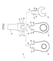
- FIG. 1 is an exploded view of a first preferred embodiment of the present invention;
- FIG 2 is a top view of the first preferred embodiment of the present invention;
- FIG. 3 is a lateral view of the first preferred embodiment of the present invention, showing turning of the driving member;
- FIG. 4 is an exploded view of a second preferred embodiment of the present invention;
- FIG. 5 is an exploded view of a third preferred embodiment of the present invention;
- FIG. 6 is an exploded view of a fourth preferred embodiment of the present invention;
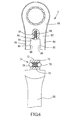
- FIG. 7 is an exploded view of a fifth preferred embodiment of the present invention;
- FIG 8 and FIG 9 are top views of the fifth preferred embodiment of the present invention, showing the driving member unlocked and locked by the control device;
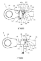
- FIG. 10 and FIG. 11 are top views of a sixth preferred embodiment of the present invention, showing the driving member unlocked and locked by the control device; and
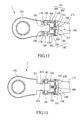
- FIG. 12 and FIG 13 are top views of a sixth preferred embodiment of the present invention, showing the driving member locked and unlocked by the control device.
- As shown in FIG 1 and FIG 2, a
wrench 1 of the first preferred embodiment of the present invention includes ahandle 10 and a set of drivingmembers 34 for replacement. - The
handle 10 has a connectingportion 12 at an end thereof and an open-end driving member 13 at opposite end. The connectingportion 12 has twoparallel arms 14 and aspace 16 between thearms 14. Each of thearms 14 has abore 18 aligned with each other. In thebores 18 of the connectingportion 12 are acoupling device 20, which includes aball 22, aspring 24 and a threadedcolumn 26. Theballs 22 have a portion extruded out of thebores 18 and received in thespace 16, and thesprings 24 urge theballs 22 respectively to keep the ball at those positions. The ends of thebores 18, which are adjacent to thespace 16, have a diameter less than that of theballs 22, such that theballs 22 will not run out of thebores 18. The connectingportion 12 further is provided with aspring 30 and aball 32 in ahole 28 at a bottom of thespace 16. - Each
driving member 34 has a driving device 36 and a connectingportion 38 at an end of the driving device 36. The driving device 36 may be open-end type, close-end type, adjustable wrench type, ratchet wrench type or other types and may have different sizes. The connectingportions 38 of thedriving members 34 are a post with a width slightly less than that of thespace 16 of thehandle 10, such that thedriving member 34 may be engaged with thehandle 10 by means of inserting the connectingportion 38 of thedriving member 34 into thespace 16 of the connectingportion 12 of thehandle 10. The connectingportion 38 of thedriving member 34 is provided with arecess 40 at opposite sides respectively to receive theballs 22 of thecoupling device 20. The connectingportion 38 is provided with aslot 42 at the opposite sides communicated with therecesses 40 respectively, such that theballs 22 may slide to recesses 40 along theslots 42 respectively. Therecesses 40 have a depth greater than that of theslots 42. - To quick couple the
driving member 34 to thehandle 10, theslots 42 of thedriving member 34 are aligned with theballs 22 to slide theballs 22 to therecesses 40. The drivingmember 34 may be coupled to thehandle 10 by inserting the connectingportion 38 of thedriving member 34 into thespace 16 of the connectingportion 12 of thehandle 10. To release the drivingmember 34, it only needs to pull the drivingmember 34 out. It is easy to know that the wrench of the present invention may replace the driving members quickly. - Except for coupling the driving
member 34 to thehandle 10, thecoupling device 20 also forms a rotation axle for the drivingmember 34 to rotate the drivingmember 34 freely, as shown in FIG. 3. - With the wrench of the present invention, there may be only a handle and a set of driving members in the tool box. User may mount the specific driving member on the handle to do the specific work.
- FIG. 4 shows a wrench 2 of the second preferred embodiment of the present invention, which is similar to the
wrench 1 of the first preferred embodiment, except that acoupling device 46 has abase 48, aspring 50 and aball 52. Thebase 48 has aslot 54 to receive thespring 50 and theball 52 therein. Thebase 48, thespring 50 and theball 52 are integrated as a module, and such module may be bought in the market easily. Thecoupling devices 46 may be screwed intobores 58 of the handle 56 directly to simplify the assembling process. - FIG. 5 shows a
wrench 3 of the third preferred embodiment of the present invention, which is similar to thewrench 1 of the first preferred embodiment, except that acoupling device 60 has ablock 62 with a convex end for replacement of the ball. Theblock 62 has aslot 64 at a rear end to receive an end of aspring 66. - FIG. 6 shows a
wrench 4 of the fourth preferred embodiment of the present invention, which includes ahandle 68 with twopost-like connecting portions 70 at opposite ends and a set of drivingmembers 80 with a U-shaped connectingportion 82 respectively. The connectingportion 70 of thehandle 68 has atransverse hole 72, in which acoupling device 70 is received. Thecoupling device 70 includes aspring 76 and twoballs 78. Thesprings 76 has opposite ends urging theballs 78 to keep theballs 78 having a portion extruded out of thehole 72. The connectingportion 82 of the drivingmember 80 has twoparallel arms 84 with arecess 86 and aslot 88 at an interior sides respectively and aspace 90 between thearms 84. The connectingportion 82 is provided with aspring 94 and aball 96 in ahole 92 at a bottom of thespace 90. The way of replacing the driving members is as same as above embodiment, so I do not describe it again. - FIG. 7 shows a
wrench 5 of the fifth preferred embodiment of the present invention, which includes ahandle 98 with a connectingportion 100 at an end thereof and acoupling device 102, which has two balls, mounted on the connectingportion 100. The connectingportion 100 has twoparallel arms 104 with abore 106 respectively, and theballs 102 are received in thebores 106. The connectingportion 100 is provided with twoinclined holes 108 on a top thereof extending to thebores 106 respectively and two fixingholes 110 extending from the top to a bottom. A set of driving members 112 (only show one driving member in the drawing), which are as same as the drivingmembers 34 of the first preferred embodiment, are selected to mount on thehandle 98 or release from thehandle 98. Thewrench 5 further comprises acontrol device 114, which includes abase 116, twoshafts 118, twosprings 120 and aplate 122. Thebase 116 has two inclined through holes 124 (referring to FIG. 8) extending from a top to a bottom and two threaded holes (not shown) on the bottom. Thebase 116 is placed on the top of the connectingportion 100 of thehandle 98, and twobolts 128 are inserted into the fixingholes 110 and screwed into the threaded holes ofbase 116 to fix the base 116 on thehandle 98. Thesprings 120 and theshafts 118 are received in the throughholes 124 of the base 116 respectively. Each of theshafts 118 has a small dimension section inserted into theinclined holes 108 of thehandle 98 and a greater dimension section left out of thebase 116, and theplate 122 is fixed to the ends of the greater dimension sections of theshafts 118. User may press theplate 122 to move theshafts 118 inwards, and thesprings 120 may return theshafts 118 when user releases theplate 122. Each of theshafts 118 has arecess 130 and a slopingportion 132 beside therecess 130. - To replace the driving
member 112, user has to press theplate 112 to move theshafts 118 inwards. In the meantime, therecesses 130 of theshafts 118 are moved to backs of theballs 102 to provide a space for theballs 102 totally received in the bores 106 (referring to FIG. 9), such that the drivingmember 112 may be easily pulled out and install another drivingmember 112. And then, user may release theplate 122 to force theballs 102 extruded out of thebores 106 because the slopingportions 132 of theshafts 118 are moved to the backs of theballs 102. As a result, the drivingmember 112 will be locked by theballs 112. - As shown in FIG 10 and FIG 11, a
wrench 6 of the sixth preferred embodiment of the present invention includes ahandle 134 and a set of driving members 136 (only show one driving member in drawing) foe replacement. Thehandle 134 has a connectingportion 138 at an end thereof with twoparallel arms 140 and aspace 142 between thearms 140. Thearms 140 are provided with abore 144 aligned with each other. The connectingportion 138 is provided with ahole 146, which is parallel to thebore 144, behind thearms 140 and atunnel 148 communicating thehole 146 and thebore 144 of onearm 140. The connectingportion 138 further is drilled with ahole 150 at a bottom of thespace 142 and crossing thehole 146, in a bottom of which aball 152 and aspring 154 are installed. Acoupling device 156, which is a shaft, is inserted into thebores 134 of the connectingportion 138 and a throughhole 158 of the drivingmember 136 to couple the drivingmember 136 to thehandle 134. Theshaft 156 has anannular slot 160 aligned with thetunnel 148. Fiveballs 1621~1625 are received in thetunnel 148. Ashaft 164 and aspring 166 are received in thehole 146, wherein theshaft 164 has arecess 168, a slopingportion 170 beside therecess 168, and aslot 172. - FIG 10 shows a driving
member 136 coupled to thehandle 134, in which the slopingportion 170 of theshaft 164 pushes theball 1625 to move a portion of theball 1621 extruded out of thetunnel 148 and entering theslot 160 of theshaft 156, such that theshaft 156 is locked by theball 1621 and the drivingmember 136 is fixed to thehandle 134 firmly. When press theshaft 164, referring to FIG. 11, theslot 172 is moved to theball 152 and therecess 172 is move to theball 1625. Theball 152 enters theslot 172 to position theshaft 164 thereat, and theball 1625 will drop in therecess 172 to move theball 1621 out of theslot 160 of theshaft 156, such that user may pull the drivingmember 136 out and replace another drivingmember 136. When thenew driving member 136 is inserted into thespace 142 of the connectingportion 138 of thehandle 134, user may press theshaft 164 along the opposite direction to move theshaft 164 back. User has to exert a little power on theshaft 164 to overcome the restriction of theball 152 and theslot 172 and thespring 166 will take over. After theshaft 164 moves, the slopingportion 170 will push theball 1625 to move theball 1621 into theslot 160 of theshaft 156, such that the drivingmember 136 will be locked. - It has to be mentioned that the
ball 1625 always has a portion received in therecess 168 of theshaft 164 to prevent theshaft 164 from escaping out of thehole 146. - As shown in FIG. 12 and FIG 13, a wrench 7 of the seventh preferred embodiment of the present invention includes a
handle 174 with a U shaped connectingportion 178. The connectingportion 178 has twoarms 178, each of which has abore 180 and acoupling device 182, which is a ball, received in thebore 180. The connectingportion 178 further has ahole 184 behind thearms 178 and parallel to thebores 180 and twotunnels 186 communicating thebores 180 and thehole 184 respectively. The connectingportion 178 is drilled with anaperture 188 at a top thereof extending to thehole 184, in which acam device 196 is received. Twoposts 190 are inserted into two ends of thehole 184, such that two L-shapedchannels 192 are formed at opposite sides of thecam device 196.Balls 194 are received in thechannels 192 respectively, and the series of the balls are in touch with thecam device 196 and the balls of thecoupling devices 182 respectively. - The
cam device 196 has twoconvex portions 202 and twoconcave portions 198. When thecam device 196 is turned with theconvex portions 202 against theballs 194, referring to FIG. 12, theconvex portions 202 will move theballs 194 outwards to force the balls of thecoupling devices 182 extruding out of thebores 180, such that thecoupling devices 182 can lock a drivingmember 200 on connectingportion 178 of thehandle 176. - When the
cam device 196 is turned with theconcave portions 198 against theballs 194, referring to FIG. 13, theballs 194 may move back into thechannel 192, and the balls of thecoupling devices 182 can be moved back into thebores 180, such that the drivingmember 200 is unlocked, and user may pull it out for replacement.
Claims (26)
- A wrench, comprising:a handle having a connecting portion at an end thereof;a set of driving members to be selected to be coupled to the handle, each of which has a driving device and a connecting portion, wherein the connecting portions of the driving members are complementary to the connecting portion of the handle; anda coupling device disposed at the connecting portion of the handle to detachably coupling the connecting portion of the driving member and the connecting portion of the handle, wherein the coupling device forms a rotation axis of the driving member, such that the driving member can rotate.
- The wrench as defined in claim 1, wherein the connecting portions are a member with two substantially parallel arms and a space between the arms and a post to be inserted into the space.
- The wrench as defined in claim 2, wherein the coupling device is provided at the arms.
- The wrench as defined in claim 3, wherein each of the arms has a bore, and the coupling device has two balls and two springs received in the bores respectively wherein the balls have portions extruded out of the bores and received in the space.
- The wrench as defined in claim 3, wherein each of the arms has a bore, and the coupling device has two bases with a slot respectively, in which a spring and a ball are received, and the bases are received in the bores with the balls having portions extruded out of the bores and received in the space.
- The wrench as defined in claim 3, wherein each of the arms has a bore, and the coupling device has two blocks and two springs received in the bores respectively, wherein each of the blocks has a convex portion at a front end and a slot at a rear end, and ends of the springs are received in the slots, and the convex portions of the blocks are extruded out of the bores and received in the space.
- The wrench as defined in claim 2, wherein the post has a through hole, in which the coupling device is received to form.
- The wrench as defined in claim 7, wherein the coupling device has a spring in the through hole and two balls at opposite ends of spring, which the balls have portions extruded out of the through hole.
- The wrench as defined in claim 7, wherein the coupling device has a spring in the through hole and two blocks at opposite ends of spring, which each of the blocks has a convex portion extruded out of the through hole and a slot to receive the end of the spring.
- The wrench as defined in claim 1, wherein the connecting portion without the coupling device is provided with a recess to receive the coupling device therein.
- The wrench as defined in claim 10, wherein the connecting portion is provided with a slot communicated with the recess.
- A wrench, comprising:a handle having a connecting portion at an end thereof;a set of driving members to be selected to be coupled to the handle, each of which has a driving device and a connecting portion, wherein the connecting portions of the driving members are complementary to the connecting portion of the handle;a coupling device disposed at the connecting portion of the handle to detachably coupling the connecting portion of the driving member and the connecting portion of the handle, wherein the coupling device forms a rotation axis of the driving member, such that the driving member can rotate; anda locking device disposed at the handle to secure the coupling device, such that the driving member is secured on the handle, and to release the coupling member, such that the driving member is free to be moved out of the handle.
- The wrench as defined in claim 12, wherein the locking device has a shaft with a recess and a sloping portion, and the shaft is moved to a position where the recess is aligned with the coupling device to receive the coupling device in the recess and to release the driving member and a position where the sloping portion is aligned with the coupling device to move the coupling device outwards and to lock the driving member.
- The wrench as defined in claim 13, wherein the coupling device has a ball.
- The wrench as defined in claim 13, wherein the connecting portion of the handle has two substantially parallel arms and a space between the arms, and each of the arms had a bore, in which the coupling device is received, and the connecting portion of the handle is provided with a hole extending to the bore in which the shaft is received.
- The wrench as defined in claim 13, wherein the locking device has a spring urging the shaft to the position where the sloping portion is aligned with the coupling device.
- The wrench as defined in claim 16, wherein locking device further comprises a base fixed on the handle, which has a hole aligned with the hole on the handle, and the shaft is received in both of the holes of the base and the handle, and the spring is received in the hole of the base.
- The wrench as defined in claim 17, wherein the locking device further comprises a plate fixed to an end of the shaft.
- The wrench as defined in claim 12, wherein the locking device has a shaft with a recess and a sloping portion and a plurality of balls lined between the coupling device and the shaft, which the shaft is moved to a position where the recess is aligned with the ball to receive the ball in the recess and to release the driving member and a position where the sloping portion is aligned with the ball to move the ball outwards and to lock the driving member.
- The wrench as defined in claim 19, wherein the connecting portion of the handle is provided with a bore, in which the coupling device is received, a hole, in which the shaft is received, and a tunnel communicating the bore and the hole, in which the ball is received.
- The wrench as defined in claim 20, wherein the handle is provided with a hole, in which a ball and a spring are received, and the shaft has a slot, whereby the shaft is moved to a position where the ball can enter the slot to position the shaft thereat.
- The wrench as defined in claim 20, wherein the coupling device has a shaft to be inserted into the bores of the connecting portion of the handle and a through hole of the connecting portion of the driving member, which the shaft has a slot to receive the ball when the sloping portion of the shaft moves the balls outwards.
- The wrench as defined in claim 12, wherein the locking device has a cam device and a plurality of balls lined between the cam device and the coupling device, wherein the cam device is turned to force the ball toward the coupling device to lock the driving member on the handle.
- The wrench as defined in claim 23, wherein the connecting portion of the handle is provided with an aperture, in which the cam device is received for free rotation, and a channel communicating the aperture and the bore, in which the balls are received.
- The wrench as defined in claim 24, wherein the coupling device has a ball.
- The wrench as defined in claim 24, wherein the channel has a hole extending to the aperture and a tunnel with opposite end communicated with the hole and the bore.
Applications Claiming Priority (1)
| Application Number | Priority Date | Filing Date | Title |
|---|---|---|---|
| US11/320,666 US7146886B1 (en) | 2005-12-30 | 2005-12-30 | Wrench capable of quick replacement of swivel driving members |
Publications (3)
| Publication Number | Publication Date |
|---|---|
| EP1803534A2 true EP1803534A2 (en) | 2007-07-04 |
| EP1803534A3 EP1803534A3 (en) | 2009-03-11 |
| EP1803534B1 EP1803534B1 (en) | 2014-03-12 |
Family
ID=37497118
Family Applications (1)
| Application Number | Title | Priority Date | Filing Date |
|---|---|---|---|
| EP06026529.5A Not-in-force EP1803534B1 (en) | 2005-12-30 | 2006-12-21 | Wrench capable of quick replacement of swivel driving members |
Country Status (3)
| Country | Link |
|---|---|
| US (1) | US7146886B1 (en) |
| EP (1) | EP1803534B1 (en) |
| CN (1) | CN101015912B (en) |
Cited By (1)
| Publication number | Priority date | Publication date | Assignee | Title |
|---|---|---|---|---|
| DE102014115953B4 (en) * | 2013-11-06 | 2017-08-31 | Bobby Hu | Tool wrench with a swivel head |
Families Citing this family (15)
| Publication number | Priority date | Publication date | Assignee | Title |
|---|---|---|---|---|
| CN101104258B (en) | 2007-08-31 | 2010-08-25 | 伯鑫工具股份有限公司 | Spanner capable of quickly replacing driving head |
| TW200916270A (en) * | 2007-10-05 | 2009-04-16 | Proxene Tools Co Ltd | Wrench with fast replaceable driving head |
| US20100175515A1 (en) * | 2009-01-10 | 2010-07-15 | Ching Chen | Wrench with releasable head |
| US9844859B2 (en) * | 2009-03-16 | 2017-12-19 | Alberto R. Cubillas | Multi-engageable tubing wrench |
| TWM417998U (en) * | 2010-12-08 | 2011-12-11 | Jin-Tan Huang | Tool head angle adjustment device |
| TWI386149B (en) * | 2010-12-21 | 2013-02-11 | Alpha Networks Inc | Pivoting assembly with press-fit positioning function |
| TW201345671A (en) * | 2012-05-04 | 2013-11-16 | Hong Ann Tool Ind Co Ltd | Pivotal swinging device |
| US9975222B2 (en) * | 2015-05-25 | 2018-05-22 | Chun-Wei Yang | Ratchet wrench |
| CN105127930A (en) * | 2015-10-17 | 2015-12-09 | 国家电网公司 | Rotation prevention tool for capping of screw |
| CN107140336A (en) * | 2017-05-05 | 2017-09-08 | 天津安固密封技术有限公司 | A tank intersecting line sealing device and its sealing method |
| US20190126440A1 (en) * | 2017-10-31 | 2019-05-02 | Heng-Yi Hsu | Angle Adjustable Pliers |
| CN110014388A (en) * | 2018-01-10 | 2019-07-16 | 刘昭志 | Improved tool group piecing devices |
| TWI758858B (en) * | 2020-09-11 | 2022-03-21 | 優鋼機械股份有限公司 | Pivot structure of hand tools |
| CN219132208U (en) * | 2022-11-17 | 2023-06-06 | 南通天茂机械制造有限公司 | Tool handle with rotary handle |
| US12459086B2 (en) | 2023-03-16 | 2025-11-04 | Snap-On Incorporated | Ratchet flex joint locking mechanism |
Family Cites Families (18)
| Publication number | Priority date | Publication date | Assignee | Title |
|---|---|---|---|---|
| US2420132A (en) * | 1945-11-27 | 1947-05-06 | Gryniuck Michael | Detachable head wrench |
| US2608894A (en) * | 1951-12-14 | 1952-09-02 | Jr Herbert G Miller | Wrench handle detachably connectible to rigid-jaw type wrench head |
| FR1212685A (en) * | 1959-01-08 | 1960-03-25 | Stefanox Ets | Flat and socket wrench with swivel and interchangeable clamping elements |
| US4541310A (en) * | 1984-08-02 | 1985-09-17 | Lindenberger Paul H | Multiple-use ratchet tool |
| US4581959A (en) | 1985-01-23 | 1986-04-15 | Joseph Troiano | Locking flex head tool |
| JPS6334080A (en) | 1986-07-24 | 1988-02-13 | ダイヤ精工株式会社 | Ratchet handle |
| US5199335A (en) | 1992-05-11 | 1993-04-06 | Easco Hand Tools, Inc. | Flex-head tool with locking feature |
| US5768960A (en) | 1995-12-11 | 1998-06-23 | Archuleta; Tarue David | Locking swivel head ratchet wrench |
| US6000302A (en) | 1998-04-07 | 1999-12-14 | Chiang; Der Ching | Tool having rotatable driving head |
| US6382058B1 (en) * | 1999-06-15 | 2002-05-07 | Greg J. Owoc | Multi-jointed wrench handle |
| US6397709B1 (en) * | 1999-08-13 | 2002-06-04 | Dean Wall | Handtool with rotatable arms |
| DE20006678U1 (en) | 2000-04-11 | 2000-06-29 | Hsieh, Chih-Ching, Fong Yuan, Taichung | Angle adjustable wrench |
| TW482064U (en) | 2000-11-15 | 2002-04-01 | Stanley Chiro Int Ltd | Structure for revolved-stem type composite wrench |
| US6336383B1 (en) * | 2001-01-26 | 2002-01-08 | Kun Chih Hung | Wrench structure |
| TW497526U (en) | 2001-07-19 | 2002-08-01 | Jr-Ching Shie | Wrench structure with easy angle adjustment |
| TW585807B (en) | 2003-01-28 | 2004-05-01 | Yan-Wen Lin | Improved wrench structure having pivotable box end |
| US6928904B2 (en) * | 2003-08-29 | 2005-08-16 | Chih-Ching Hsien | Hand tool having a quick driving effect |
| USD506373S1 (en) | 2003-11-17 | 2005-06-21 | Chih-Ching Hsien | Wrench |
-
2005
- 2005-12-30 US US11/320,666 patent/US7146886B1/en not_active Expired - Lifetime
-
2006
- 2006-12-21 EP EP06026529.5A patent/EP1803534B1/en not_active Not-in-force
- 2006-12-27 CN CN200610170666.7A patent/CN101015912B/en not_active Expired - Fee Related
Non-Patent Citations (1)
| Title |
|---|
| None |
Cited By (1)
| Publication number | Priority date | Publication date | Assignee | Title |
|---|---|---|---|---|
| DE102014115953B4 (en) * | 2013-11-06 | 2017-08-31 | Bobby Hu | Tool wrench with a swivel head |
Also Published As
| Publication number | Publication date |
|---|---|
| EP1803534A3 (en) | 2009-03-11 |
| US7146886B1 (en) | 2006-12-12 |
| CN101015912A (en) | 2007-08-15 |
| EP1803534B1 (en) | 2014-03-12 |
| CN101015912B (en) | 2014-03-12 |
Similar Documents
| Publication | Publication Date | Title |
|---|---|---|
| US7146886B1 (en) | Wrench capable of quick replacement of swivel driving members | |
| US7036401B2 (en) | Extendable spline-drive socket system | |
| US11059151B2 (en) | Impact socket | |
| US7895920B2 (en) | Open end ratchet wrench | |
| US6968758B2 (en) | Wrench adaptor for driving screw driver bits | |
| AU2017257440A1 (en) | Power-driven direct drive ratchet/wrench tool | |
| US20100024608A1 (en) | Tool connecting rod with convertible connectors | |
| US9669526B2 (en) | Tools with socket retainers | |
| US6951154B2 (en) | Ratchet socket tool | |
| US4947939A (en) | Structure of motorized screw bolt driving tool | |
| US20220324034A1 (en) | Operating key for stationary and driven tool holders | |
| US6715385B2 (en) | Combination tool for assembling and dismantling a lock nut of a bearing of a wheel axle of a wheeled vehicle | |
| US7654175B2 (en) | Slide-driver | |
| EP3156178B1 (en) | Ratchet tool | |
| US8096214B2 (en) | Ratcheting head with internal self-locking adapter related applications | |
| EP1329293A2 (en) | Adjustable reaction arm for torque power tool and torque power tool provided therewith | |
| US6843579B2 (en) | Illuminative universal joint | |
| US7261022B1 (en) | Insertion type hand tool | |
| CA2569268C (en) | Wrench capable of quick replacement of swivel driving member | |
| US6862957B2 (en) | Combination tool for assembling and dismantling a lock nut of a bearing of wheel axle of a wheeled vehicle | |
| US20030131692A1 (en) | Socket wrench | |
| US20060060032A1 (en) | Reset gear, method of use, and ratchet wrench utilizing said gear | |
| US20070137440A1 (en) | Socket provided with a ratchet device | |
| US20050050642A1 (en) | Chain detaching handle tool | |
| US6902047B2 (en) | Ratchet device comprising two sets of symmetrical pawls to enhance torsion thereof |
Legal Events
| Date | Code | Title | Description |
|---|---|---|---|
| PUAI | Public reference made under article 153(3) epc to a published international application that has entered the european phase |
Free format text: ORIGINAL CODE: 0009012 |
|
| AK | Designated contracting states |
Kind code of ref document: A2 Designated state(s): AT BE BG CH CY CZ DE DK EE ES FI FR GB GR HU IE IS IT LI LT LU LV MC NL PL PT RO SE SI SK TR |
|
| AX | Request for extension of the european patent |
Extension state: AL BA HR MK YU |
|
| RIN1 | Information on inventor provided before grant (corrected) |
Inventor name: WU, ARTHUR |
|
| PUAL | Search report despatched |
Free format text: ORIGINAL CODE: 0009013 |
|
| AK | Designated contracting states |
Kind code of ref document: A3 Designated state(s): AT BE BG CH CY CZ DE DK EE ES FI FR GB GR HU IE IS IT LI LT LU LV MC NL PL PT RO SE SI SK TR |
|
| AX | Request for extension of the european patent |
Extension state: AL BA HR MK RS |
|
| 17P | Request for examination filed |
Effective date: 20090702 |
|
| 17Q | First examination report despatched |
Effective date: 20090814 |
|
| AKX | Designation fees paid |
Designated state(s): AT BE BG CH CY CZ DE DK EE ES FI FR GB GR HU IE IS IT LI LT LU LV MC NL PL PT RO SE SI SK TR |
|
| REG | Reference to a national code |
Ref country code: DE Ref legal event code: R079 Ref document number: 602006040582 Country of ref document: DE Free format text: PREVIOUS MAIN CLASS: B25B0023000000 Ipc: B25B0013040000 |
|
| GRAP | Despatch of communication of intention to grant a patent |
Free format text: ORIGINAL CODE: EPIDOSNIGR1 |
|
| RIC1 | Information provided on ipc code assigned before grant |
Ipc: B25G 1/06 20060101ALI20131021BHEP Ipc: B25B 13/08 20060101ALI20131021BHEP Ipc: B25B 13/56 20060101ALI20131021BHEP Ipc: B25B 13/04 20060101AFI20131021BHEP |
|
| INTG | Intention to grant announced |
Effective date: 20131120 |
|
| GRAS | Grant fee paid |
Free format text: ORIGINAL CODE: EPIDOSNIGR3 |
|
| GRAA | (expected) grant |
Free format text: ORIGINAL CODE: 0009210 |
|
| AK | Designated contracting states |
Kind code of ref document: B1 Designated state(s): AT BE BG CH CY CZ DE DK EE ES FI FR GB GR HU IE IS IT LI LT LU LV MC NL PL PT RO SE SI SK TR |
|
| REG | Reference to a national code |
Ref country code: GB Ref legal event code: FG4D |
|
| REG | Reference to a national code |
Ref country code: CH Ref legal event code: EP |
|
| REG | Reference to a national code |
Ref country code: AT Ref legal event code: REF Ref document number: 655923 Country of ref document: AT Kind code of ref document: T Effective date: 20140315 |
|
| REG | Reference to a national code |
Ref country code: IE Ref legal event code: FG4D |
|
| REG | Reference to a national code |
Ref country code: DE Ref legal event code: R096 Ref document number: 602006040582 Country of ref document: DE Effective date: 20140424 |
|
| REG | Reference to a national code |
Ref country code: DE Ref legal event code: R082 Ref document number: 602006040582 Country of ref document: DE Representative=s name: LANGPATENT ANWALTSKANZLEI IP LAW FIRM, DE |
|
| REG | Reference to a national code |
Ref country code: CH Ref legal event code: NV Representative=s name: LANGPATENT ANWALTSKANZLEI, CH |
|
| REG | Reference to a national code |
Ref country code: NL Ref legal event code: VDEP Effective date: 20140312 |
|
| PG25 | Lapsed in a contracting state [announced via postgrant information from national office to epo] |
Ref country code: LT Free format text: LAPSE BECAUSE OF FAILURE TO SUBMIT A TRANSLATION OF THE DESCRIPTION OR TO PAY THE FEE WITHIN THE PRESCRIBED TIME-LIMIT Effective date: 20140312 |
|
| REG | Reference to a national code |
Ref country code: AT Ref legal event code: MK05 Ref document number: 655923 Country of ref document: AT Kind code of ref document: T Effective date: 20140312 |
|
| REG | Reference to a national code |
Ref country code: LT Ref legal event code: MG4D |
|
| PG25 | Lapsed in a contracting state [announced via postgrant information from national office to epo] |
Ref country code: CY Free format text: LAPSE BECAUSE OF FAILURE TO SUBMIT A TRANSLATION OF THE DESCRIPTION OR TO PAY THE FEE WITHIN THE PRESCRIBED TIME-LIMIT Effective date: 20140312 Ref country code: FI Free format text: LAPSE BECAUSE OF FAILURE TO SUBMIT A TRANSLATION OF THE DESCRIPTION OR TO PAY THE FEE WITHIN THE PRESCRIBED TIME-LIMIT Effective date: 20140312 Ref country code: SE Free format text: LAPSE BECAUSE OF FAILURE TO SUBMIT A TRANSLATION OF THE DESCRIPTION OR TO PAY THE FEE WITHIN THE PRESCRIBED TIME-LIMIT Effective date: 20140312 |
|
| PG25 | Lapsed in a contracting state [announced via postgrant information from national office to epo] |
Ref country code: LV Free format text: LAPSE BECAUSE OF FAILURE TO SUBMIT A TRANSLATION OF THE DESCRIPTION OR TO PAY THE FEE WITHIN THE PRESCRIBED TIME-LIMIT Effective date: 20140312 |
|
| PG25 | Lapsed in a contracting state [announced via postgrant information from national office to epo] |
Ref country code: IS Free format text: LAPSE BECAUSE OF FAILURE TO SUBMIT A TRANSLATION OF THE DESCRIPTION OR TO PAY THE FEE WITHIN THE PRESCRIBED TIME-LIMIT Effective date: 20140712 Ref country code: NL Free format text: LAPSE BECAUSE OF FAILURE TO SUBMIT A TRANSLATION OF THE DESCRIPTION OR TO PAY THE FEE WITHIN THE PRESCRIBED TIME-LIMIT Effective date: 20140312 Ref country code: RO Free format text: LAPSE BECAUSE OF FAILURE TO SUBMIT A TRANSLATION OF THE DESCRIPTION OR TO PAY THE FEE WITHIN THE PRESCRIBED TIME-LIMIT Effective date: 20140312 Ref country code: CZ Free format text: LAPSE BECAUSE OF FAILURE TO SUBMIT A TRANSLATION OF THE DESCRIPTION OR TO PAY THE FEE WITHIN THE PRESCRIBED TIME-LIMIT Effective date: 20140312 Ref country code: EE Free format text: LAPSE BECAUSE OF FAILURE TO SUBMIT A TRANSLATION OF THE DESCRIPTION OR TO PAY THE FEE WITHIN THE PRESCRIBED TIME-LIMIT Effective date: 20140312 Ref country code: BE Free format text: LAPSE BECAUSE OF FAILURE TO SUBMIT A TRANSLATION OF THE DESCRIPTION OR TO PAY THE FEE WITHIN THE PRESCRIBED TIME-LIMIT Effective date: 20140312 Ref country code: BG Free format text: LAPSE BECAUSE OF FAILURE TO SUBMIT A TRANSLATION OF THE DESCRIPTION OR TO PAY THE FEE WITHIN THE PRESCRIBED TIME-LIMIT Effective date: 20140612 |
|
| PG25 | Lapsed in a contracting state [announced via postgrant information from national office to epo] |
Ref country code: AT Free format text: LAPSE BECAUSE OF FAILURE TO SUBMIT A TRANSLATION OF THE DESCRIPTION OR TO PAY THE FEE WITHIN THE PRESCRIBED TIME-LIMIT Effective date: 20140312 Ref country code: PL Free format text: LAPSE BECAUSE OF FAILURE TO SUBMIT A TRANSLATION OF THE DESCRIPTION OR TO PAY THE FEE WITHIN THE PRESCRIBED TIME-LIMIT Effective date: 20140312 Ref country code: SK Free format text: LAPSE BECAUSE OF FAILURE TO SUBMIT A TRANSLATION OF THE DESCRIPTION OR TO PAY THE FEE WITHIN THE PRESCRIBED TIME-LIMIT Effective date: 20140312 Ref country code: ES Free format text: LAPSE BECAUSE OF FAILURE TO SUBMIT A TRANSLATION OF THE DESCRIPTION OR TO PAY THE FEE WITHIN THE PRESCRIBED TIME-LIMIT Effective date: 20140312 |
|
| REG | Reference to a national code |
Ref country code: DE Ref legal event code: R097 Ref document number: 602006040582 Country of ref document: DE |
|
| PG25 | Lapsed in a contracting state [announced via postgrant information from national office to epo] |
Ref country code: PT Free format text: LAPSE BECAUSE OF FAILURE TO SUBMIT A TRANSLATION OF THE DESCRIPTION OR TO PAY THE FEE WITHIN THE PRESCRIBED TIME-LIMIT Effective date: 20140714 |
|
| PLBE | No opposition filed within time limit |
Free format text: ORIGINAL CODE: 0009261 |
|
| STAA | Information on the status of an ep patent application or granted ep patent |
Free format text: STATUS: NO OPPOSITION FILED WITHIN TIME LIMIT |
|
| PG25 | Lapsed in a contracting state [announced via postgrant information from national office to epo] |
Ref country code: DK Free format text: LAPSE BECAUSE OF FAILURE TO SUBMIT A TRANSLATION OF THE DESCRIPTION OR TO PAY THE FEE WITHIN THE PRESCRIBED TIME-LIMIT Effective date: 20140312 |
|
| 26N | No opposition filed |
Effective date: 20141215 |
|
| REG | Reference to a national code |
Ref country code: DE Ref legal event code: R097 Ref document number: 602006040582 Country of ref document: DE Effective date: 20141215 |
|
| PG25 | Lapsed in a contracting state [announced via postgrant information from national office to epo] |
Ref country code: IT Free format text: LAPSE BECAUSE OF FAILURE TO SUBMIT A TRANSLATION OF THE DESCRIPTION OR TO PAY THE FEE WITHIN THE PRESCRIBED TIME-LIMIT Effective date: 20140312 |
|
| PG25 | Lapsed in a contracting state [announced via postgrant information from national office to epo] |
Ref country code: SI Free format text: LAPSE BECAUSE OF FAILURE TO SUBMIT A TRANSLATION OF THE DESCRIPTION OR TO PAY THE FEE WITHIN THE PRESCRIBED TIME-LIMIT Effective date: 20140312 Ref country code: LU Free format text: LAPSE BECAUSE OF FAILURE TO SUBMIT A TRANSLATION OF THE DESCRIPTION OR TO PAY THE FEE WITHIN THE PRESCRIBED TIME-LIMIT Effective date: 20141221 |
|
| REG | Reference to a national code |
Ref country code: IE Ref legal event code: MM4A |
|
| PG25 | Lapsed in a contracting state [announced via postgrant information from national office to epo] |
Ref country code: IE Free format text: LAPSE BECAUSE OF NON-PAYMENT OF DUE FEES Effective date: 20141221 |
|
| REG | Reference to a national code |
Ref country code: FR Ref legal event code: PLFP Year of fee payment: 10 |
|
| PG25 | Lapsed in a contracting state [announced via postgrant information from national office to epo] |
Ref country code: MC Free format text: LAPSE BECAUSE OF FAILURE TO SUBMIT A TRANSLATION OF THE DESCRIPTION OR TO PAY THE FEE WITHIN THE PRESCRIBED TIME-LIMIT Effective date: 20140312 |
|
| PG25 | Lapsed in a contracting state [announced via postgrant information from national office to epo] |
Ref country code: GR Free format text: LAPSE BECAUSE OF FAILURE TO SUBMIT A TRANSLATION OF THE DESCRIPTION OR TO PAY THE FEE WITHIN THE PRESCRIBED TIME-LIMIT Effective date: 20140613 |
|
| PG25 | Lapsed in a contracting state [announced via postgrant information from national office to epo] |
Ref country code: TR Free format text: LAPSE BECAUSE OF FAILURE TO SUBMIT A TRANSLATION OF THE DESCRIPTION OR TO PAY THE FEE WITHIN THE PRESCRIBED TIME-LIMIT Effective date: 20140312 Ref country code: HU Free format text: LAPSE BECAUSE OF FAILURE TO SUBMIT A TRANSLATION OF THE DESCRIPTION OR TO PAY THE FEE WITHIN THE PRESCRIBED TIME-LIMIT; INVALID AB INITIO Effective date: 20061221 |
|
| REG | Reference to a national code |
Ref country code: CH Ref legal event code: PCAR Free format text: NEW ADDRESS: C/O CHRISTIAN LANG TAEAETSCHESTRASSE 38 POSTFACH 454, 3914 BLATTEN B. NATERS (CH) |
|
| REG | Reference to a national code |
Ref country code: FR Ref legal event code: PLFP Year of fee payment: 11 |
|
| REG | Reference to a national code |
Ref country code: FR Ref legal event code: PLFP Year of fee payment: 12 |
|
| PGFP | Annual fee paid to national office [announced via postgrant information from national office to epo] |
Ref country code: FR Payment date: 20211220 Year of fee payment: 16 Ref country code: GB Payment date: 20211222 Year of fee payment: 16 |
|
| PGFP | Annual fee paid to national office [announced via postgrant information from national office to epo] |
Ref country code: CH Payment date: 20211222 Year of fee payment: 16 |
|
| PGFP | Annual fee paid to national office [announced via postgrant information from national office to epo] |
Ref country code: DE Payment date: 20211222 Year of fee payment: 16 |
|
| REG | Reference to a national code |
Ref country code: DE Ref legal event code: R119 Ref document number: 602006040582 Country of ref document: DE |
|
| REG | Reference to a national code |
Ref country code: CH Ref legal event code: PL |
|
| GBPC | Gb: european patent ceased through non-payment of renewal fee |
Effective date: 20221221 |
|
| PG25 | Lapsed in a contracting state [announced via postgrant information from national office to epo] |
Ref country code: LI Free format text: LAPSE BECAUSE OF NON-PAYMENT OF DUE FEES Effective date: 20221231 Ref country code: GB Free format text: LAPSE BECAUSE OF NON-PAYMENT OF DUE FEES Effective date: 20221221 Ref country code: DE Free format text: LAPSE BECAUSE OF NON-PAYMENT OF DUE FEES Effective date: 20230701 Ref country code: CH Free format text: LAPSE BECAUSE OF NON-PAYMENT OF DUE FEES Effective date: 20221231 |
|
| PG25 | Lapsed in a contracting state [announced via postgrant information from national office to epo] |
Ref country code: FR Free format text: LAPSE BECAUSE OF NON-PAYMENT OF DUE FEES Effective date: 20221231 |