EP1803471A1 - Air filtering apparatus - Google Patents
Air filtering apparatus Download PDFInfo
- Publication number
- EP1803471A1 EP1803471A1 EP06025987A EP06025987A EP1803471A1 EP 1803471 A1 EP1803471 A1 EP 1803471A1 EP 06025987 A EP06025987 A EP 06025987A EP 06025987 A EP06025987 A EP 06025987A EP 1803471 A1 EP1803471 A1 EP 1803471A1
- Authority
- EP
- European Patent Office
- Prior art keywords
- air
- filtering apparatus
- water
- gas
- contact member
- Prior art date
- Legal status (The legal status is an assumption and is not a legal conclusion. Google has not performed a legal analysis and makes no representation as to the accuracy of the status listed.)
- Granted
Links
- 238000001914 filtration Methods 0.000 title claims abstract description 90
- XLYOFNOQVPJJNP-UHFFFAOYSA-N water Substances O XLYOFNOQVPJJNP-UHFFFAOYSA-N 0.000 claims abstract description 247
- 239000007788 liquid Substances 0.000 claims abstract description 85
- 238000007664 blowing Methods 0.000 claims abstract description 76
- 238000005192 partition Methods 0.000 claims abstract description 73
- 238000000638 solvent extraction Methods 0.000 claims abstract description 3
- QVGXLLKOCUKJST-UHFFFAOYSA-N atomic oxygen Chemical compound [O] QVGXLLKOCUKJST-UHFFFAOYSA-N 0.000 claims description 22
- 239000001301 oxygen Substances 0.000 claims description 22
- 229910052760 oxygen Inorganic materials 0.000 claims description 22
- MHAJPDPJQMAIIY-UHFFFAOYSA-N Hydrogen peroxide Chemical compound OO MHAJPDPJQMAIIY-UHFFFAOYSA-N 0.000 claims description 20
- QWPPOHNGKGFGJK-UHFFFAOYSA-N hypochlorous acid Chemical compound ClO QWPPOHNGKGFGJK-UHFFFAOYSA-N 0.000 claims description 16
- 239000008399 tap water Substances 0.000 claims description 13
- 235000020679 tap water Nutrition 0.000 claims description 13
- CBENFWSGALASAD-UHFFFAOYSA-N Ozone Chemical compound [O-][O+]=O CBENFWSGALASAD-UHFFFAOYSA-N 0.000 claims description 11
- 239000011248 coating agent Substances 0.000 claims description 10
- 238000000576 coating method Methods 0.000 claims description 10
- 238000010276 construction Methods 0.000 description 21
- 241000700605 Viruses Species 0.000 description 10
- 244000005700 microbiome Species 0.000 description 9
- 238000011146 sterile filtration Methods 0.000 description 8
- 101100480512 Caenorhabditis elegans tag-51 gene Proteins 0.000 description 7
- 238000006243 chemical reaction Methods 0.000 description 7
- 238000005868 electrolysis reaction Methods 0.000 description 7
- 230000001965 increasing effect Effects 0.000 description 7
- 241000894006 Bacteria Species 0.000 description 6
- 238000007667 floating Methods 0.000 description 6
- 230000007246 mechanism Effects 0.000 description 6
- 239000007921 spray Substances 0.000 description 6
- 241000712461 unidentified influenza virus Species 0.000 description 6
- 239000000463 material Substances 0.000 description 5
- 239000003595 mist Substances 0.000 description 5
- 230000001954 sterilising effect Effects 0.000 description 5
- 238000003466 welding Methods 0.000 description 5
- 241000233866 Fungi Species 0.000 description 4
- 238000010586 diagram Methods 0.000 description 4
- JEIPFZHSYJVQDO-UHFFFAOYSA-N iron(III) oxide Inorganic materials O=[Fe]O[Fe]=O JEIPFZHSYJVQDO-UHFFFAOYSA-N 0.000 description 4
- 230000005855 radiation Effects 0.000 description 4
- 239000002994 raw material Substances 0.000 description 4
- KZBUYRJDOAKODT-UHFFFAOYSA-N Chlorine Chemical compound ClCl KZBUYRJDOAKODT-UHFFFAOYSA-N 0.000 description 3
- 239000000460 chlorine Substances 0.000 description 3
- 229910052801 chlorine Inorganic materials 0.000 description 3
- -1 chlorine ions Chemical class 0.000 description 3
- XLYOFNOQVPJJNP-ZSJDYOACSA-N heavy water Substances [2H]O[2H] XLYOFNOQVPJJNP-ZSJDYOACSA-N 0.000 description 3
- BASFCYQUMIYNBI-UHFFFAOYSA-N platinum Substances [Pt] BASFCYQUMIYNBI-UHFFFAOYSA-N 0.000 description 3
- 238000011045 prefiltration Methods 0.000 description 3
- 229920005989 resin Polymers 0.000 description 3
- 239000011347 resin Substances 0.000 description 3
- XEEYBQQBJWHFJM-UHFFFAOYSA-N Iron Chemical compound [Fe] XEEYBQQBJWHFJM-UHFFFAOYSA-N 0.000 description 2
- 150000001768 cations Chemical class 0.000 description 2
- 238000004140 cleaning Methods 0.000 description 2
- 238000001816 cooling Methods 0.000 description 2
- 230000000694 effects Effects 0.000 description 2
- 230000001939 inductive effect Effects 0.000 description 2
- 208000015181 infectious disease Diseases 0.000 description 2
- 230000007774 longterm Effects 0.000 description 2
- 238000012423 maintenance Methods 0.000 description 2
- 229910052751 metal Inorganic materials 0.000 description 2
- 239000002184 metal Substances 0.000 description 2
- 230000001590 oxidative effect Effects 0.000 description 2
- 230000000149 penetrating effect Effects 0.000 description 2
- ZAMOUSCENKQFHK-UHFFFAOYSA-N Chlorine atom Chemical compound [Cl] ZAMOUSCENKQFHK-UHFFFAOYSA-N 0.000 description 1
- MYMOFIZGZYHOMD-UHFFFAOYSA-N Dioxygen Chemical compound O=O MYMOFIZGZYHOMD-UHFFFAOYSA-N 0.000 description 1
- 102000018697 Membrane Proteins Human genes 0.000 description 1
- 108010052285 Membrane Proteins Proteins 0.000 description 1
- OUUQCZGPVNCOIJ-UHFFFAOYSA-M Superoxide Chemical compound [O-][O] OUUQCZGPVNCOIJ-UHFFFAOYSA-M 0.000 description 1
- RTAQQCXQSZGOHL-UHFFFAOYSA-N Titanium Chemical compound [Ti] RTAQQCXQSZGOHL-UHFFFAOYSA-N 0.000 description 1
- BZHJMEDXRYGGRV-UHFFFAOYSA-N Vinyl chloride Chemical compound ClC=C BZHJMEDXRYGGRV-UHFFFAOYSA-N 0.000 description 1
- 239000002253 acid Substances 0.000 description 1
- 229910052782 aluminium Inorganic materials 0.000 description 1
- XAGFODPZIPBFFR-UHFFFAOYSA-N aluminium Chemical compound [Al] XAGFODPZIPBFFR-UHFFFAOYSA-N 0.000 description 1
- 238000013459 approach Methods 0.000 description 1
- 230000001580 bacterial effect Effects 0.000 description 1
- 238000005452 bending Methods 0.000 description 1
- 238000009395 breeding Methods 0.000 description 1
- 230000001488 breeding effect Effects 0.000 description 1
- 239000000919 ceramic Substances 0.000 description 1
- 230000008859 change Effects 0.000 description 1
- 239000011247 coating layer Substances 0.000 description 1
- 239000000470 constituent Substances 0.000 description 1
- 238000001514 detection method Methods 0.000 description 1
- 238000003411 electrode reaction Methods 0.000 description 1
- 238000002474 experimental method Methods 0.000 description 1
- 238000001125 extrusion Methods 0.000 description 1
- 239000004744 fabric Substances 0.000 description 1
- 229920002313 fluoropolymer Polymers 0.000 description 1
- 238000010097 foam moulding Methods 0.000 description 1
- 230000020169 heat generation Effects 0.000 description 1
- 238000010438 heat treatment Methods 0.000 description 1
- TUJKJAMUKRIRHC-UHFFFAOYSA-N hydroxyl Chemical compound [OH] TUJKJAMUKRIRHC-UHFFFAOYSA-N 0.000 description 1
- 230000000415 inactivating effect Effects 0.000 description 1
- 238000009434 installation Methods 0.000 description 1
- 230000002452 interceptive effect Effects 0.000 description 1
- 150000002500 ions Chemical class 0.000 description 1
- 229910052741 iridium Inorganic materials 0.000 description 1
- GKOZUEZYRPOHIO-UHFFFAOYSA-N iridium atom Chemical compound [Ir] GKOZUEZYRPOHIO-UHFFFAOYSA-N 0.000 description 1
- 229910052742 iron Inorganic materials 0.000 description 1
- 239000004973 liquid crystal related substance Substances 0.000 description 1
- 238000012986 modification Methods 0.000 description 1
- 230000004048 modification Effects 0.000 description 1
- 239000002245 particle Substances 0.000 description 1
- 230000002093 peripheral effect Effects 0.000 description 1
- 239000002984 plastic foam Substances 0.000 description 1
- 229910052697 platinum Inorganic materials 0.000 description 1
- LEYNFUIKYCSXFM-UHFFFAOYSA-N platinum tantalum Chemical compound [Ta][Pt][Ta] LEYNFUIKYCSXFM-UHFFFAOYSA-N 0.000 description 1
- 229920005672 polyolefin resin Polymers 0.000 description 1
- 238000012545 processing Methods 0.000 description 1
- 238000005086 pumping Methods 0.000 description 1
- 230000009257 reactivity Effects 0.000 description 1
- 230000009467 reduction Effects 0.000 description 1
- 229910001220 stainless steel Inorganic materials 0.000 description 1
- 239000010935 stainless steel Substances 0.000 description 1
- 238000004659 sterilization and disinfection Methods 0.000 description 1
- 239000013589 supplement Substances 0.000 description 1
- 230000001502 supplementing effect Effects 0.000 description 1
- 230000009897 systematic effect Effects 0.000 description 1
- 238000012360 testing method Methods 0.000 description 1
- 238000009834 vaporization Methods 0.000 description 1
- 230000008016 vaporization Effects 0.000 description 1
Images







Classifications
-
- F—MECHANICAL ENGINEERING; LIGHTING; HEATING; WEAPONS; BLASTING
- F24—HEATING; RANGES; VENTILATING
- F24F—AIR-CONDITIONING; AIR-HUMIDIFICATION; VENTILATION; USE OF AIR CURRENTS FOR SCREENING
- F24F8/00—Treatment, e.g. purification, of air supplied to human living or working spaces otherwise than by heating, cooling, humidifying or drying
- F24F8/80—Self-contained air purifiers
-
- A—HUMAN NECESSITIES
- A61—MEDICAL OR VETERINARY SCIENCE; HYGIENE
- A61L—METHODS OR APPARATUS FOR STERILISING MATERIALS OR OBJECTS IN GENERAL; DISINFECTION, STERILISATION OR DEODORISATION OF AIR; CHEMICAL ASPECTS OF BANDAGES, DRESSINGS, ABSORBENT PADS OR SURGICAL ARTICLES; MATERIALS FOR BANDAGES, DRESSINGS, ABSORBENT PADS OR SURGICAL ARTICLES
- A61L9/00—Disinfection, sterilisation or deodorisation of air
- A61L9/14—Disinfection, sterilisation or deodorisation of air using sprayed or atomised substances including air-liquid contact processes
-
- C—CHEMISTRY; METALLURGY
- C02—TREATMENT OF WATER, WASTE WATER, SEWAGE, OR SLUDGE
- C02F—TREATMENT OF WATER, WASTE WATER, SEWAGE, OR SLUDGE
- C02F1/00—Treatment of water, waste water, or sewage
- C02F1/46—Treatment of water, waste water, or sewage by electrochemical methods
- C02F1/461—Treatment of water, waste water, or sewage by electrochemical methods by electrolysis
-
- F—MECHANICAL ENGINEERING; LIGHTING; HEATING; WEAPONS; BLASTING
- F24—HEATING; RANGES; VENTILATING
- F24F—AIR-CONDITIONING; AIR-HUMIDIFICATION; VENTILATION; USE OF AIR CURRENTS FOR SCREENING
- F24F1/00—Room units for air-conditioning, e.g. separate or self-contained units or units receiving primary air from a central station
- F24F1/0007—Indoor units, e.g. fan coil units
- F24F1/0043—Indoor units, e.g. fan coil units characterised by mounting arrangements
- F24F1/005—Indoor units, e.g. fan coil units characterised by mounting arrangements mounted on the floor; standing on the floor
-
- F—MECHANICAL ENGINEERING; LIGHTING; HEATING; WEAPONS; BLASTING
- F24—HEATING; RANGES; VENTILATING
- F24F—AIR-CONDITIONING; AIR-HUMIDIFICATION; VENTILATION; USE OF AIR CURRENTS FOR SCREENING
- F24F1/00—Room units for air-conditioning, e.g. separate or self-contained units or units receiving primary air from a central station
- F24F1/0007—Indoor units, e.g. fan coil units
- F24F1/0071—Indoor units, e.g. fan coil units with means for purifying supplied air
-
- F—MECHANICAL ENGINEERING; LIGHTING; HEATING; WEAPONS; BLASTING
- F24—HEATING; RANGES; VENTILATING
- F24F—AIR-CONDITIONING; AIR-HUMIDIFICATION; VENTILATION; USE OF AIR CURRENTS FOR SCREENING
- F24F1/00—Room units for air-conditioning, e.g. separate or self-contained units or units receiving primary air from a central station
- F24F1/02—Self-contained room units for air-conditioning, i.e. with all apparatus for treatment installed in a common casing
- F24F1/0328—Self-contained room units for air-conditioning, i.e. with all apparatus for treatment installed in a common casing with means for purifying supplied air
- F24F1/035—Self-contained room units for air-conditioning, i.e. with all apparatus for treatment installed in a common casing with means for purifying supplied air characterised by the mounting or arrangement of filters
-
- F—MECHANICAL ENGINEERING; LIGHTING; HEATING; WEAPONS; BLASTING
- F24—HEATING; RANGES; VENTILATING
- F24F—AIR-CONDITIONING; AIR-HUMIDIFICATION; VENTILATION; USE OF AIR CURRENTS FOR SCREENING
- F24F13/00—Details common to, or for air-conditioning, air-humidification, ventilation or use of air currents for screening
- F24F13/20—Casings or covers
-
- F—MECHANICAL ENGINEERING; LIGHTING; HEATING; WEAPONS; BLASTING
- F24—HEATING; RANGES; VENTILATING
- F24F—AIR-CONDITIONING; AIR-HUMIDIFICATION; VENTILATION; USE OF AIR CURRENTS FOR SCREENING
- F24F13/00—Details common to, or for air-conditioning, air-humidification, ventilation or use of air currents for screening
- F24F13/22—Means for preventing condensation or evacuating condensate
-
- F—MECHANICAL ENGINEERING; LIGHTING; HEATING; WEAPONS; BLASTING
- F24—HEATING; RANGES; VENTILATING
- F24F—AIR-CONDITIONING; AIR-HUMIDIFICATION; VENTILATION; USE OF AIR CURRENTS FOR SCREENING
- F24F13/00—Details common to, or for air-conditioning, air-humidification, ventilation or use of air currents for screening
- F24F13/28—Arrangement or mounting of filters
-
- F—MECHANICAL ENGINEERING; LIGHTING; HEATING; WEAPONS; BLASTING
- F24—HEATING; RANGES; VENTILATING
- F24F—AIR-CONDITIONING; AIR-HUMIDIFICATION; VENTILATION; USE OF AIR CURRENTS FOR SCREENING
- F24F8/00—Treatment, e.g. purification, of air supplied to human living or working spaces otherwise than by heating, cooling, humidifying or drying
- F24F8/10—Treatment, e.g. purification, of air supplied to human living or working spaces otherwise than by heating, cooling, humidifying or drying by separation, e.g. by filtering
- F24F8/117—Treatment, e.g. purification, of air supplied to human living or working spaces otherwise than by heating, cooling, humidifying or drying by separation, e.g. by filtering using wet filtering
-
- F—MECHANICAL ENGINEERING; LIGHTING; HEATING; WEAPONS; BLASTING
- F24—HEATING; RANGES; VENTILATING
- F24F—AIR-CONDITIONING; AIR-HUMIDIFICATION; VENTILATION; USE OF AIR CURRENTS FOR SCREENING
- F24F8/00—Treatment, e.g. purification, of air supplied to human living or working spaces otherwise than by heating, cooling, humidifying or drying
- F24F8/20—Treatment, e.g. purification, of air supplied to human living or working spaces otherwise than by heating, cooling, humidifying or drying by sterilisation
-
- F—MECHANICAL ENGINEERING; LIGHTING; HEATING; WEAPONS; BLASTING
- F24—HEATING; RANGES; VENTILATING
- F24F—AIR-CONDITIONING; AIR-HUMIDIFICATION; VENTILATION; USE OF AIR CURRENTS FOR SCREENING
- F24F8/00—Treatment, e.g. purification, of air supplied to human living or working spaces otherwise than by heating, cooling, humidifying or drying
- F24F8/20—Treatment, e.g. purification, of air supplied to human living or working spaces otherwise than by heating, cooling, humidifying or drying by sterilisation
- F24F8/24—Treatment, e.g. purification, of air supplied to human living or working spaces otherwise than by heating, cooling, humidifying or drying by sterilisation using sterilising media
-
- F—MECHANICAL ENGINEERING; LIGHTING; HEATING; WEAPONS; BLASTING
- F24—HEATING; RANGES; VENTILATING
- F24F—AIR-CONDITIONING; AIR-HUMIDIFICATION; VENTILATION; USE OF AIR CURRENTS FOR SCREENING
- F24F8/00—Treatment, e.g. purification, of air supplied to human living or working spaces otherwise than by heating, cooling, humidifying or drying
- F24F8/20—Treatment, e.g. purification, of air supplied to human living or working spaces otherwise than by heating, cooling, humidifying or drying by sterilisation
- F24F8/24—Treatment, e.g. purification, of air supplied to human living or working spaces otherwise than by heating, cooling, humidifying or drying by sterilisation using sterilising media
- F24F8/26—Treatment, e.g. purification, of air supplied to human living or working spaces otherwise than by heating, cooling, humidifying or drying by sterilisation using sterilising media using ozone
-
- F—MECHANICAL ENGINEERING; LIGHTING; HEATING; WEAPONS; BLASTING
- F24—HEATING; RANGES; VENTILATING
- F24F—AIR-CONDITIONING; AIR-HUMIDIFICATION; VENTILATION; USE OF AIR CURRENTS FOR SCREENING
- F24F13/00—Details common to, or for air-conditioning, air-humidification, ventilation or use of air currents for screening
- F24F13/20—Casings or covers
- F24F2013/205—Mounting a ventilator fan therein
-
- Y—GENERAL TAGGING OF NEW TECHNOLOGICAL DEVELOPMENTS; GENERAL TAGGING OF CROSS-SECTIONAL TECHNOLOGIES SPANNING OVER SEVERAL SECTIONS OF THE IPC; TECHNICAL SUBJECTS COVERED BY FORMER USPC CROSS-REFERENCE ART COLLECTIONS [XRACs] AND DIGESTS
- Y02—TECHNOLOGIES OR APPLICATIONS FOR MITIGATION OR ADAPTATION AGAINST CLIMATE CHANGE
- Y02A—TECHNOLOGIES FOR ADAPTATION TO CLIMATE CHANGE
- Y02A50/00—TECHNOLOGIES FOR ADAPTATION TO CLIMATE CHANGE in human health protection, e.g. against extreme weather
- Y02A50/20—Air quality improvement or preservation, e.g. vehicle emission control or emission reduction by using catalytic converters
Definitions
- the present invention relates to a portable air filtering apparatus that can remove (inactivate, sterilize, etc.) microorganisms such as virus, bacteria, fungus, etc. floating in the air, for example, and particularly relates to a portable floor-mount type air filtering apparatus.
- the above-described sterilizing apparatus works effectively under a use environment which electrolytic water mist of mine particles easily reach, that is, in a relatively small space, however, it does not work effectively in a user environment which the electrolytic water mist hardly reaches, that is in a large space such as a kindergarten, an elementary/junior/high school, long-term care insurance facilities, a hospital or the like.
- a first object of the present invention is to provide a floor-mount type air filtering apparatus that stably perform sterile filtration of air passing through a filter and further can perform sterile filtration of air in a large space.
- a second object of the present invention is to provide a floor-mount type air filtering apparatus that can water-tightly secure a water receiving tray to a partition plate.
- a third object of the present invention is to provide a floor-mount type air filtering apparatus in which a support tray and a circulating pump do not interfere with each other when the support tray is detached.
- a fourth object of the present invention is to provide a floor-mount type air filtering apparatus that can secure the flow rate and amount of air blown from an air blower to a gas-liquid contact member.
- a fifth object of the present invention is to provide a floor-mount type air filtering apparatus that can effectively cool a control board portion for controlling an electrolytic water generating unit, etc.
- an air filtering apparatus for example, a floor-mount type air filtering apparatus
- a housing (2) for example, a floor-mount type air filtering apparatus
- a gas-liquid contact member (5) for receiving electrolytic water from an electrolytic water supply unit
- an air blowing fan (7) for blowing air to the gas-liquid contact member so that the air is brought into contact with the electrolytic water flowing along the gas-liquid contact member
- a controller 52, 53
- a water receiving tray (9) for receiving the electrolytic water flowing out from the gas-liquid contact member, wherein the gas-liquid contact member (5) and the air blowing fan (7) are disposed in one (60) of the chambers, and one of the controller and the electrolytic water supply unit is disposed in the other chamber (61 or 62) of the at least two chambers.
- the inside of the housing of the air filtering apparatus is sectioned into plural chambers by at least one partition plate, and one chamber is used as an air filtering chamber for performing sterile filtration while the other chamber is used as an electric-component chamber for accommodating electric component parts or an electrolytic water supply chamber for accommodating the electrolytic water supply unit. Accordingly, the electrolytic water in the air filtering chamber is prevented from spattering into the electric component chamber and further the constituent elements of the floor-mount type air filtering apparatus can be accommodated in the housing in order and in a compact arrangement.
- one end portion (9A) of the water receiving tray (9) may penetrate through one partition plate (51) so as to extend to the other chamber (61).
- the end portion of the water receiving tray penetrates through the partition plate so as to extend to the other chamber side, and thus the water receiving tray can be water-tightly secured to the partition plate without inducing any gap between the partition plate and the water receiving tray. Furthermore, the end portion of the water receiving tray is inserted through an opening portion formed in the partition plate to fix the water receiving tray to the partition plate, and thus the fixing work can be easily performed.
- a cover member (72) for covering the end portion (9A) of the water receiving tray (9) may be provided in the other chamber (61).
- antirust coating may be applied to the water receiving tray (9).
- a water return portion (back board) (71) may be provided to the end portion of the water receiving tray.
- the water receiving tray (9) may be disposed so as to downwardly incline from the other chamber (61) to the one chamber (60).
- the electrolytic water contains active oxygen species achieved by electrolyzing water such as tap water or the like, and the active oxygen specifies contain at least one of hypochlorous acid, ozone and hydrogen peroxide.
- the electrolytic water supply unit may contain a support tray (10) for receiving electrolytic water flowing from the water receiving tray (9) located below the gas-liquid contact member (5) and stocking the electrolytic water concerned, and a circulating pump (13) that is inserted in the support tray and pumps up the electrolytic water stocked in the support tray, wherein one of a projecting portion (50A) and a rail groove (53) in which the projecting portion (50A) is fitted so as to be movable along the rail groove (53) is provided to at least one of both the side surfaces (10c, 10d) of the support tray (10), the other of the projecting portion and the rail groove is provided to at least one of the inner side surface (2Z) of the housing and the side surface (52c) of the partition plate (52), the inner side surface (2Z) and the side surface (52c) facing the side surfaces (10c, 10d) of the support tray (10), and the rail groove (53) is designed so that the projecting portion (50A)
- the rail groove (53) may comprise a vertical movement portion (53b)and a horizontal movement portion (53a) intercommunicating with the vertical movement portion (53b), the support tray (10) being movable in one of a downward direction and an obliquely downward direction and horizontally movable along the horizontal movement portion (53a) and detached from one end of the horizontal movement portion (53a) to the outside of the housing (2) when the support tray (10) is detached from the housing (2) .
- the support tray by moving the projecting portion of the support tray along the rail groove, the support tray can be detached from the housing without interfering with the circulating pump.
- the rail groove comprises the horizontal movement portion extending substantially in the horizontal direction from the take-out side of the support tray to the back side of the housing, and the vertical movement portion extending from the back end of the horizontal movement portion upwardly or obliquely upwardly. Therefore, the support tray can be guided along the vertical movement portion downwardly or obliquely downwardly from the state that the support tray is secured to the housing, and further drawn out (taken out) along the horizontal movement portion.
- the rail groove is formed such that the projecting portion is downwardly guided along the rail groove until the circulating pump is located at the outside of the support tray when the support tray is detached from the housing. Therefore, by moving the projecting portion of the support tray along the rail groove, the support tray can be detached from the housing while the support tray and the circulating pump do not interfere with each other.
- the support tray can be guided downwardly or obliquely downwardly along the vertical movement portion from the state that the support tray is secured to the housing. Therefore, by moving the projecting portion of the support tray along the rail groove, the support tray can be detached from the housing while the interference between the support tray and the circulating pump can be more surely prevented. Still furthermore, the support tray can be drawn out to the take-out side along the horizontal movement portion, and thus the support tray can be horizontally drawn out without being inclined.
- the above-described floor-mount type air filtering apparatus may be further equipped with an air guide plate for guiding air from an air blow-out port (7a) of the air blowing fan (7) to the gas-liquid contact member (5).
- the air guide plate may comprise an extension portion (50a) extending in a flow direction of air blown out from the air blowing fan (7), and a guide portion (50b) that is connected to the extension portion (50a) and extends obliquely from the blow-out port (7a) toward the gas-liquid contact member.
- the floor-mount type air filtering apparatus may be further equipped with a support plate (8) for isolating the gas-liquid contact member and the air blowing fan from each other, and the support plate (8) is provided with an opening (8a) through which the air blown out from the air blowing fan is passed.
- the inclination angle of the guide portion (50b) is adjustable with respect to the extension portion (50a).
- the length of the extension portion (50a) is adjustable.
- the air blown out from the air blowing fan is passed through the extension portion, so that the air can be guided to the guide portion without reducing the air flow rate and the air flow amount.
- the gas-liquid contact member and the air blowing fan can be isolated from each other by the support plate, and the opening through which the air blown out from the air blowing fan is passed is formed in the support plate. Therefore, the mount side of the air blowing fan and the mount side of the gas-liquid contact member are isolated from each other by the support plate, so that the air blown out from the air blowing fan is prevented from returning to the air blowing fan side.
- the inclination angle of the guide portion is adjustable with respect to the extension portion, and thus the air flow direction can be varied in conformity with the shape and size of the gas-liquid contact member and the mount position of the gas-liquid contact member.
- the length of the extension portion is adjustable, and thus the length of the extension portion can be adjusted so that neither turbulent flow nor eddy occurs in the air stream from the air blowing fan.
- the air blown out from the air blowing fan is temporarily guided by the extension portion of the air guide plate, whereby neither turbulent flow nor eddy occurs in the air stream, and thus the air flow rate and air flow amount of the air blown out from the air blowing fan can be kept with no change. Furthermore, indoor air can be fed from the blow-out port of the air blowing fan to the gas-liquid contact member located at a remote position by the guide portion, whereby the air can be uniformly applied onto the gas-liquid contact member.
- the air of the air blowing fan can be prevented from escaping to the air blowing fan side.
- the air flow amount of the air fed to the gas-liquid contact member can be increased.
- the air flowing direction can be changed in conformity with the size and position of the gas-liquid contact member. Accordingly, air (for example, indoor air) can be evenly applied to the whole gas-liquid contact member.
- the controller may contain a control board portion having electric parts and a heat sink for the electric parts, and the heat sink may be disposed so as to penetrate through an opening (51) formed in the partition plate (51) and face a suction port (3) of the air blowing fan (7).
- the inside of the housing (2) may be vertically partitioned by one partition plate (51), the suction port (3) of the air blowing fan (7) may be substantially horizontally disposed, and air blown out from the air blowing fan to the gas-liquid contact member (5) is sucked from the suction port (3) that is formed in the housing and located at the lower side of the air blowing fan.
- the electrolytic water supply unit may have electrodes for electrolyzing water to generate electrolytic water and the electric parts may contain a part for controlling electrodes of the electrolytic water supply unit.
- the electrolytic water generated in the electrolytic water supply unit may be electrolytic water containing active oxygen species achieved by supplying current to the electrodes and electrolyzing tap water.
- the active oxygen specifies may contain at least one of hypochlorous acid, ozone and hydrogen peroxide.
- the heat sink of the electrical parts of the control board portion penetrates through the opening formed in the partition plate, and is located so as to face the suction port of the air flowing fan. Therefore, indoor air flows while coming into contact with the heat sink, and then is sucked into the suction port of the air blowing fan. Accordingly, the cooling of the heat sink is promoted, and thus heat radiation of the electrical parts is also promoted. Furthermore, since the heat sink is disposed so as to penetrate through the opening of the partition plate, the heat sink may be inserted from the other chamber into the one chamber while the control board portion is secured to the heat sink in advance, and then secured to the partition plate by screws or the like. Therefore, the work of fixing the heat sink can be enhanced.
- reference numeral 1 represents an air filtering apparatus.
- the following description will be described by representatively using a floor-mount type air filtering apparatus which is used under the state that it is put on the floor, however, the air filtering apparatus is not limited to this type of air filtering apparatus.
- the floor-mount type air filtering apparatus 1 has a box-shaped housing 2, and the housing 2 comprises leg pieces 2A, a front panel 2B and a top panel 2C, and an operating lid 2D, an opening/closing lid 2E are arranged in a lateral direction at both the sides of the top panel 2C.
- partition plates 51, 52 extending in the vertical direction are provided, and the inside of the housing 2 is divided into three chambers (an air filtering chamber 60, an electric component chamber 61 and a water supply chamber 62) by the partition plates 51, 52.
- the number of the partition plates is not limited to two, that is, the divided chambers is not necessarily limited to three.
- At least one partition plate may be provided to divide the inside of the housing into at least two chambers.
- An elongated suction port 3 is formed at the lower side of the air filtering chamber (one chamber) 60 formed at the center of the housing 2, and a pre-filter 3A is disposed at the upper side of the suction port 3.
- An air blowing fan 7 is disposed above the pre-filter 3A, and a gas-liquid contact member 5 having high water retentivity is disposed above the air blowing fan 7 so as to be tilted as shown in Fig. 3.
- a water receiving tray 9 for receiving electrolytic water flowing out from the gas-liquid contact member 5 is disposed below the gas-liquid contact member 5.
- the water receiving tray 9 is designed to have a substantially V-shaped section as shown in Fig. 3.
- an elongated blow-out port 4 from which blown air passing through the gas-liquid contact member 5 is blown out is formed above the gas-liquid contact member 5.
- Reference numeral 8 represents a support plate of the air blowing fan 7, and this support plate 8 is suspended substantially horizontally between the partition plates 51 and 52.
- the air blowing fan 7 is secured to the support plate 8, and an opening portion 8a penetrating through the support plate 8 in the vertical direction is formed at the center position (see Fig. 3) in the right and left direction of the gas-liquid contact member 5 on the plane of the support plate 8.
- the air blow-out port 7a of the air blowing fan 7 is disposed so as to face the opening portion 8a, and air blown out from the air blowing fan 7 is upwardly blown out.
- the opening portion 8a and the air blow-out port 7a of the air blowing fan 7 are designed to be substantially equal to each other in shape and size. Furthermore, the aperture area of each of the air blow-out port 7a of the air blowing fan and the opening portion 8a is set to be smaller than the horizontal project area of the gas-liquid contact member 5 located above the opening portion 8a.
- an electrolytic water supply unit comprising a water supply tank support tray (support tray) 10 for stocking electrolytic water received by the water receiving tray 9, a circulating pump 13 for pumping up the electrolytic water stocked in the support tray 10, an electrolytic bath in which the water pumped by the circulating pump 13 is electrolyzed to generate electrolytic water, a detachable water supply tank 11, etc. is disposed in the water supply chamber 62 formed at the right side of the housing 2 as shown in Figs. 2A and 2B.
- Fig. 2A shows a state where the water supply tank 11 and a part of the water supply tank support tray 10 shown in Fig. 2B are detached.
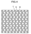
- the gas-liquid contact member 5 comprises a filter member having a honeycomb structure, and it is designed so that a broad gas-liquid contact area can be secured, electrolytic water can be dropped and clogging occurs hardly. That is, as shown in Fig. 4, the gas-liquid contact member 5 comprises corrugated raw materials 5A and flat-plate type raw materials 5B joined to the corrugated raw materials 5A, and it is designed in a honeycomb structure as a whole.
- These raw materials 5A and 5B are formed of a material having little reactivity to electrolytic water described later, that is, a material which is hardly deteriorated by electrolytic water, such as a polyolefin resin group, a PET resin group, a vinyl chloride resin group, a fluorocarbon polymer group, a ceramic resin group or the like.
- the inclination (tilt) angle ⁇ of the gas-liquid contact member 5 is preferably set to 30° or more. If the inclination angle ⁇ is less than 30°, dropped electrolytic water does not flow along the slope of the gas-liquid contact member 5, but falls downwardly.
- the inclination angle ⁇ approaches to 90°, the air flow passage of the air passing through the gas-liquid contact member 5 is nearly horizontal, and thus it is more difficult to blow out the air upwardly.
- the air blow-out direction concerned is set to the horizontal direction, it is impossible to blow out air to a remote place, and thus the apparatus is unsuitable for air filtering in a large space. Accordingly, it is preferable that the inclination angle ⁇ satisfies 80°> ⁇ >30°, and in this embodiment, the inclination angle ⁇ is set to about 40°.
- Figs. 5A to 5C show a mechanism for dropping electrolytic water to the gas-liquid contact member 5.
- the water receiving tray 9 is disposed below the gas-liquid contact member 5 as described above, and the water supply tank support tray (hereinafter referred to as "support tray") 10 intercommunicates with the water receiving tray 9 or the support tray 10 is disposed at the lower side of the water receiving tray 9.
- support tray the water supply tank support tray
- the water receiving tray 9 is disposed so as to be downwardly inclined to the support tray 10, and thus electrolytic water received by the water receiving tray 9 more easily flows to the support tray 10.
- the support tray 10 is disposed at the downstream side of the water receiving tray 9.
- the water supply tank 11 for supplying (supplementing) water containing chlorine ions (for example, tap water) and the circulating pump 13 are disposed in the support tray 10.
- the electrolytic bath 31 of the electrolytic water generating unit is connected to the circulating pump 13, and an electrolytic water supply pipe 17 is connected to the electrolytic bath 31.
- the electrolytic water supply pipe 17 has many water spray holes (not shown) on the outer peripheral portion thereof, and it is inserted in a water spray portion (box) 5C formed at the upper edge portion of the gas-liquid contact member 5 as shown in Fig. 5B.
- the electrolytic bath 31 has plural pairs of electrodes 32 and 33. By supplying current to these electrodes 32 and 33, water flowing into the electrolytic bath 31 is electrolyzed to generate active oxygen species.
- the active oxygen species are defined as molecules having higher oxidizing activity than normal oxygen molecules and relating materials, and contain so-called narrowly-defined active oxygen such as superoxide anion, singlet oxygen, hydroxyl radical, hydrogen peroxide, etc. and also so-called broadly-defined active oxygen such as ozone, hypohalous acid, hypochlorous acid, etc.
- the electrolytic bath 31 is disposed in proximity to the gas-liquid contact member 5, and it immediately supply the gas-liquid contact member 5 with active oxygen species generated by electrolyzing water pumped by the circulating pump 13.
- Each of the electrodes 32 and 33 is an electrode plate comprising a base of Ti (titan) and a coating layer of Ir (iridium), Pt (platinum), and the current value applied to the electrodes 32, 33 is set to several mA to several tens mA (milliampere) /cm 2 (square centimeter) in current density to generate a predetermined free residual chlorine concentration (for example, 1mg (milligram)/l (liter)).
- HClO hypochlorous acid
- various microorganisms such as bacteria, virus, etc.
- microorganisms such as virus, bacteria, etc. floating in the air passing through the gas-liquid contact member 5 can be inactivated.
- Odor also reacts with hypochlorous acid in the electrolytic water when passing through the gas-liquid contact member 5, so that it is ionized and dissolved in the electrolytic water. Therefore, the odor can be removed from the air and thus the air is deodorized.
- the contact area between air and electrolytic water in the gas-liquid contact member 5 is increased. Therefore, according to this embodiment, from the viewpoint of increasing the contact area, it is preferable that the gas-liquid contact member 5 is disposed so as to extend substantially from end to end in the lateral direction in the compartmented chamber (i.e., the air filtering chamber 60).
- the water receiving tray 9 is required to be water-tightly fixed to the partition plate 51 so that no electrolytic water leaks from the gap between the partition plate 51 and the water receiving tray 9.
- the water receiving tray 9 and the partition plate 51 are welded to each other to water-tightly fix the water receiving tray 9 to the partition plate 51.
- the welding portion is easily oxidized by electrolytic water and also the welding work is cumbersome.
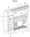
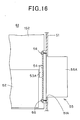
- the water receiving tray 9 disposed below the gas-liquid contact member 5 is disposed so that one end thereof at the electric component chamber (61) side is higher than the other end thereof at the water supply chamber (62) side as shown in Fig. 6 (that is, the water receiving tray 9 is obliquely downwardly disposed from the electric component chamber side to the water supply chamber side), and also the upper end portion (end portion) 9A of the water receiving tray penetrates through the partition plate 51 so as to extend to the electric component chamber (61) side so that no electrolytic water leaks downwardly from the gap between the water receiving tray 9 and the partition plate 51.
- a sponge type seal member 74 is attached to the back side of the water receiving tray 9, and an opening 51A having substantially the same shape as the cross-sectional shape of the water receiving tray 9 (containing the seal member 74) (in this embodiment, substantially V-shape) is formed in the partition plate 51.
- the upper end portion 9A of the water receiving tray 9 is disposed so as to penetrate through the opening 51A of the partition plate 51 and extend to the electrical component chamber (61) side.
- a water return portion (throating unit) 71 is formed at the upper end portion 9A of the water receiving tray 9.
- the water return portion 71 is formed so as to be bent by folding back the lower edge portion of the upper end portion 9A of the water receiving tray 9 upwardly, and it prevents electrolytic water stocked in the water receiving tray 9 from flowing into the electric component chamber 61.
- the water receiving tray 9 is disposed so as to be downwardly inclined from the electric component chamber 61 to the air filtering chamber 60, and thus the electrolytic water in the water receiving tray 9 is prevented from flowing back. Even when electrolytic water is trapped in the water receiving tray 9, the electrolytic water can be prevented from invading into the electric component chamber 61 by the water return portion 7 formed at the upper end portion 9A of the water receiving tray 9.
- the water receiving tray 9 is inserted from the electric component chamber 61 through the opening 51A of the partition plate 51 to the air filtering chamber 60, and then the other end portion of the water receiving tray 9 is inserted through an opening 52A formed in the partition plate 52 so as to extend to the water supply chamber 62 side as shown in Fig. 8, whereby the water receiving tray 9 is secured to the partition plates 51 and 52.
- a cover member 72 covering the upper end portion 9A of the water receiving tray 9 may be fixed at one side surface of the partition plate 51 which faces the electrical component chamber (61) side.
- This cover member 72 is provided with fixing pieces 72A and 72B extending upwardly and downwardly from both the upper and lower surfaces of the cover member 72 respectively, and fixing holes 73 are formed in these fixing pieces 72A and 72B.
- screw holes 51B are formed at the positions corresponding to the fixing holes 73 in the partition plate 51, and the cover member 72 is fixed by screws 75 (see Fig. 8).
- the cover member 72 prevents air containing electrolytic water from invading from the air filtering chamber 60 through the opening 51A into the electrical component chamber 61.
- the surfaces of the water receiving tray 9, the partition plate 51 and the partition plate 52 are subjected to antirust coating such as cation coating or the like.
- antirust coating such as cation coating or the like.
- hypochlorous acid has a property of oxidizing and rusting metal such as iron, etc. Therefore, according to the above construction, the antirust coating is applied to the surface of the water receiving tray 9 receiving electrolytic water at all times and the surfaces of the partition plates 51 and 52 adjacent to the water receiving tray 9, thereby preventing occurrence of rust in the water receiving tray 9 and the partition plates 51 and 52.
- the water receiving tray 9 is secured to the partition plates 51 and 52 by inserting the water receiving tray 9 into the openings 51A and 52A.
- the effect of the antirust coating is prevented from being lost by heat of welding, and also occurrence of rust in the water receiving tray 9 and the partition plates 51 and 52 can be prevented.
- antirust coating is applied to the water receiving tray 9 and the partition plates 51 and 52 in advance, so that it is unnecessary to newly apply antirust processing to the joint portions of these parts, and the assembly work of these members can be easily performed.
- the water receiving tray 9 and the partition plates 51 and 52 are subjected to antirust coating.
- the water receiving tray and the partition plates may be formed of stainless steel (sus304).
- Fig. 1 when the operating lid 2D is opened, an operation panel (not shown) is exposed. By operating this operation panel, the operation of the floor-mount type air filtering apparatus 1 is started. When this operation is started, the circulating pump 13 is driven, and water (for example, tap water) stocked in the support tray 10 is supplied to the electrolytic bath 31.
- water for example, tap water
- the water is electrolyzed by supplying current to the electrodes 32 and 33 to generate electrolytic water containing active oxygen specifies.
- This electrolytic water is passed through the spray holes (not shown) of the electrolytic water supply pipe 17, and sprayed into the water spray portion (box) 5C.
- the electrolytic water thus sprayed infiltrates into the upper edge portion of the gas-liquid contact member 5 and gradually diffuse to the lower portion of the gas-liquid contact member 5.
- the water supply system is a circulating system, and when the amount of water is reduced due to vaporization or the like, a suitable amount of water (tap water or the like) is supplemented through the water supply tank 11 into the support tray 10.
- a suitable amount of water (tap water or the like) is supplemented through the water supply tank 11 into the support tray 10.
- the opening/closing lid 2E (see Fig. 1) is opened, and the water supply tank 11 is taken out to supplement water (tap water or the like) into the water supply tank 11.
- the inside of the floor-mount type housing 2 is divided into the air filtering chamber 60 and the electric component chamber 61 (and/or the water supply unit 62) by the partition plate 51 (and/or the partition plate 52), and the gas-liquid contact member 5 which is disposed substantially from end to end in the lateral direction and supplied with electrolytic water from the electrolytic bath 31, and the air blowing fan 7 for blowing indoor air to the gas-liquid contact member 5 are provided in the air filtering chamber 60. Furthermore, the controller for controlling the air blowing fan 7, the electrolytic bath 31, etc. is provided in the electronic component chamber 61.
- the water receiving tray 9 for receiving electrolytic water flowing out from the gas-liquid contact member 5 is disposed below the gas-liquid contact member 5, and the end portion 9A of the water receiving tray 9 penetrates through the partition plate 51 and extends to the electric component chamber 61. Therefore, no gap occurs between the partition plate 51 and the water receiving tray 9, and the water receiving tray 9 can be water-tightly secured to the partition plate 51. Furthermore, according to this embodiment, the water receiving tray 9 is inserted into the opening 51A formed in the partition plate 51 and secured to the partition plate 51, and thus it is unnecessary to carry out a welding work or screw clamping work, and thus the water receiving tray 9 can be simply secured to the partition plate 51.
- the cover member 72 covering the end portion 9A of the water receiving tray 9 is secured to the electric component chamber (61) side of the partition plate 51, and thus air containing electrolytic water is prevented from flowing from the air filtering chamber 60 through the opening 51A of the partition plate 51 into the electric component chamber 61. Therefore occurrence of rust in the electrical parts in the electrical component chamber 61 can be prevented.
- the surface of the water receiving tray 9 and the surface of the partition plate 51 are subjected to antirust coating such as cation coating or the like, and thus occurrence of rust in the water receiving tray 9 receiving electrolytic water at all times and the partition plate 51 adjacent to the water receiving tray 9 can be prevented.
- indoor air sucked from the suction port 3 provided at the lower portion of the housing 2 is brought into contact with electrolytic water dropped to the gas-liquid contact member 5, and then blown out from the air blow-out port 4 provided at the upper portion of the housing 2. Therefore, even when the floor-mount type air filtering apparatus 1 is set up in a so-called large space such as a kindergarten, an elementary/junior/high school, long-term care insurance facilities, a hospital or the like, indoor air which has been brought into contact with electrolytic water and thus subjected to sterile filtration can be blown out to a remote place in a large space, so that the air filtering operation in a large space can be effectively performed.
- a so-called large space such as a kindergarten, an elementary/junior/high school, long-term care insurance facilities, a hospital or the like
- electrolytic water containing hypochlorous acid, etc. is collected in the water receiving tray 9, and flows to the adjacent support tray 10. Therefore, no microorganism occurs in each tray and thus occurrence of slime is prevented. Accordingly, the cleaning and maintenance frequency of each tray can be reduced, and the labor of maintenance, etc. can be reduced.
- the concentration of active oxygen species in electrolytic water to a target concentration.
- the target concentration is normally set to a value enough to inactivate microorganisms such as virus, bacteria, fungus, etc. which frequently exist in a set-up place of the floor-mount type air filtering apparatus (for example, school).
- the concentration of the active oxygen specifies (for example, hypochlorous acid) in the electrolytic water can he adjusted by changing the current flowing through the electrodes 32 and 33 or the voltage applied between the electrodes 32 and 33.
- the concentration of hypochlorous acid can be changed to a high value. Accordingly, the concentration of active oxygen species can be changed by merely adjusting the voltage applied to the electrodes or adjusting the current flowing through the electrodes without using any new device, and thus the cost can be reduced and the space can be saved.
- condensed materials filtered from air by electrolytic water is precipitated at the bottom portion of the support tray, and thus it is preferable to periodically detach the support tray from the air filtering apparatus and clean the support tray.
- the circulating pump 13 is inserted in the support tray as shown in Fig. 5A, and thus when the support tray is drawn out from the inside of the housing to the front side of the air filtering apparatus, the support tray and the circulating pump interfere with each other. Therefore, the support tray is not smoothly detached from the housing.
- the following construction may be adopted.
- Fig. 10 is a perspective view showing a support tray 10.
- the support tray 10 is formed of foamed material, and designed to have a substantially rectangular parallelepiped outer shape.
- the support tray 10 is designed to be hollow, and has an opened upper surface. Furthermore, the inside of the support tray 10 is divided into right and left spaces by a partition wall 10a.
- the circulating pup 13 is inserted in the support tray 10 so that the water suction port 13a of the circulating pump 13 is located in the left space, and also the water supply tank 11 is supported in the right space.
- the partition wall 10a has a groove 10b formed at the center portion thereof, and electrolytic water freely flows in the right-and-left direction.
- a projecting portion 50A is provided at the lower portion of the back side of the right surface portion 10c of the support tray 10, and also a support tag 51 is provided at the lower portion of the front side of the right side surface portion 10c so that the flat portions thereof face in the vertical direction.
- the projecting portion 50A and the support tag 51 project outwardly from the right surface portion 10c, and they are formed integrally with the support tray 10 in the plastic foam molding process.
- the projecting portion 50A and the support tag 51 may be also provided to the left surface portion 10d of the support tray 10 so as to be symmetric with those of the right surface portion 10c.
- Fig. 11 is a perspective view showing a lower portion of the water supply chamber 62 to which the support tray 10 is secured.
- the left surface (wall) 52c of the water supply chamber 62 is formed by the partition plate 62
- the right side surface (wall) 2Z of the water supply chamber 62 is formed by the side plate 2X of the housing 2.
- a pair of guide plates 52A for guiding the support tray 10 when the support tray 10 is attached to or detached from the housing 2 are provided on both the wall surfaces 52c and 2Z. With respect to the guide plates 52, only one guide plate 52 may be provided to one of the wall surfaces 52c and 2Z.
- a rail groove 53 to which the projecting portion 50A of the support tray 10 is fitted and a holding groove 54 to which the support tag 51 of the support tray 10 is fitted are formed in the guide plate 52.
- the rail groove 53 comprises a horizontal movement portion 53a extending horizontally from the surface portion 2Y of the housing 2 in the backward direction of the housing, a vertical movement portion 53b extending upwardly or obliquely upwardly from the back-side end portion of the horizontal movement portion 53a to the back side of the housing, and a fixing groove portion 53c which slightly extends horizontally from the upper end portion of the vertical movement portion 53b in the backward direction of the housing.
- the holding groove 54 is located substantially at the same height as the fixing groove portion 53c, and extends horizontally from the surface portion 2Y of the housing 2 in the backward direction.
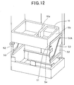
- the circulating pump 13 and the water supply tank 11 are inserted in the support tray 10 as shown in Fig. 5A. Furthermore, as shown in Fig. 12, when the support tray 10 is mounted in the water supply chamber 62 of the housing 2, the projecting portion 50A is fitted in the fixing groove portion 53c of the rail groove 53, and the support tag 51 is fitted in the holding groove 54.
- the support tray 10 When the support tray 10 is detached from the above state, the support tray 10 is first horizontally drawn out to the surface portion 2Y side of the housing 2 to release the engagement between the support tag 51 and the holding groove 54.
- This horizontal movement distance is set so that the inner wall of the support tray 10 and each of the circulating pump 13 and the water supply tank 11 does not interfere with each other.
- the support tray 10 is obliquely downwardly moved while keeping the support tray 10 in a horizontal position. At this time, the projecting portion of the support tray 10 is guided along the extending direction of the vertical movement portion 53b, whereby the support tray 10 is obliquely downwardly moved along a fixed passage.
- the shape of the support tray 10 and the moving passage of the support tray 10 are determined so that the inner wall of the back side of the support tray 10 and each of the circulating pump 13 and the water supply tank 11 do not interfere with each other.
- the support tray 10 is moved until the circulating pump 13 and the water supply tank 11 are located at the outside of the support tray 10 under the state that the support tray 10 is guided to the lower end of the vertical movement portion 53b.
- the support tray 10 is horizontally drawn out to the surface portion 2Y side of the housing 2 while keeping the support tray 10 horizontally.
- the projecting portion 50A of the support tray 10 is guided along the extending direction of the horizontal movement portion 53a, whereby the support tray 10 is horizontally moved.
- the projecting portion 50A is detached from an open portion 53 of the rail groove 53, thereby detaching the support tray 10 from the housing 2.
- the support tray 10 When the support tray 10 is mounted in the housing 2, the support tray 10 is moved in the reverse way to mount the support tray 10 in the housing so that the support tray 10 and each of the circulating pump 13 and the water supply tank 11 do not interfere with each other.
- the rail groove 53 is designed so that the projecting portion 50 is guided downwardly along the rail groove 53 until the circulating pump 13 is located at the outside of the support tray 10 when the support tray 10 is detached from the inside of the housing 2. Accordingly, by moving the projecting portion 50 of the support tray 10 along the rail groove 53, the support tray can be detached while the projecting portion 50 of the support tray 10 and the circulating pump 13 do not interfere with each other.
- the support tray 10 is obliquely downwardly guided along the vertical movement portion 53b from the state that the support tray 10 is mounted in the housing Therefore, by moving the projecting portion 50 of the support tray 10 along the rail groove 53, the support tray 10 can be detached so that the support tray 10 and the circulating pump 13 do not interfere with each other. Furthermore, the support tray 10 can be drawn out to the take-out side along the horizontal movement portion 53b, and thus the support tray 10 can be horizontally drawn out without the support tray 10 being inclined.
- the projecting portion 50 is provided to the support tray 10, and the rail groove 53 is provided to the housing 2 (partition plate 62) side.
- the rail groove 53 may be provided to the support tray 10 while the projecting portion 50 is provided to the housing 2 (partition plate 62) side. Accordingly, the support tray 10 can be detached while the support tray 10 and the circulating pup 13 do not interfere with each other.
- the vertical movement portion 53b is formed so as to be inclined, however, it may be formed so as to be vertical. Accordingly, the support tray 10 can be detached so that the support tray 10 and the circulating pup 13 do not interfere with each other.
- the air blowing fan may be designed to have an air blowing port having the same outer shape as the gas-liquid contact member.
- the air blowing fan whose air blowing port has a large aperture area as described above needs a large set-up space, and thus it makes it difficult to miniaturize the air filtering apparatus.
- Fig. 13 shows a floor-mount type air filtering apparatus having a mechanism for enabling indoor air blown out from the air blowing fan to be evenly applied to the whole of the gas-liquid contact member all over without increasing the scale of the air filtering apparatus, and corresponds to a back side view of the floor-mount air filtering apparatus of Fig. 2.
- the view of the opening portion 8a is enlarged.
- a pair of air guide plates 50 may be provided at the opening portion 8a so as to be symmetrically disposed in the right-and-left direction in Fig. 13.
- the lower side end portions of the air guide plates 50 are fixed to the support plate 8.
- Each air guide plate 50 comprises an extension portion 50a extending upwardly from the lower end portion thereof, and a guide portion 50b extending obliquely upwardly from the upper end portion of the extension portion 50a toward the gas-liquid contact member 5 located at a remote place from the air blowing fan 7.
- the extension portion 50A and the guide portion 50b of the air guide plate 50 are formed integrally with each other by folding sheet metal.
- air blown out upwardly from the air blow-out port 7a of the air blowing fan 7 is further upwardly blown out from the opening portion 8a of the support plate 8, and upwardly guided along the extension portion 50a of the air guide plate 50.
- the air blown out along the extension portion 50a is upwardly guided with no occurrence of turbulent flow or eddy and also without reducing the air flow rate and the air flow amount.
- the air guided along the extension portion 50a is further guided along the inclination of the guide portion 50b toward the gas-liquid contact member 5 located at a remote place from the air blowing port 7a of the air blowing fan 7.
- the air flow rate at the gas-liquid contact member 5 located at the outside of the air blowing port 7a of the air blowing fan 7 was equal to about 0.3m/s to 0.4m/sec.
- the air flow rate at the gas-liquid contact member 5 located at the outside of the air blowing port 7a of the air blow fan 7 was equal to 1m/sec or less.
- air blown out upwardly from the air blowing port 7a of the air blowing fan 7 is upwardly guided toward the gas-liquid contact member 5 by the air guide plates, whereby neither turbulent flow nor eddy occurs in the air stream and also the air flow rate and the air flow amount of the air blown out from the air blowing fan 7 can be secured. Furthermore, by providing the guide portion 50b, the air can be fed from the air blowing port 7a of the air blowing fan 7 toward the gas-liquid contact member 5 located at a remote place.
- the extension portion 50A and the guide portion 50b of the air guide plate 50 are formed integrally with each other. However, they may be formed separately from each other. In this case, they are detachably assembled with each other by screws or the like. Furthermore, a plurality of guide portions 50b which are different in inclination angle may be prepared and selectively used, so that the inclination angle of the air guide plate 50 being used can be freely adjusted. Accordingly, the flow direction of air to be blown to the gas-liquid contact member 5 can be adjusted.
- the position of the guide portion 50b may be designed to be slidable in the vertical direction, so that the vertical length of the extension portion 50a can be increased. Accordingly, the flow direction of air to be blown to the gas-liquid contact member 5 can be also adjusted.
- the electrical component chamber 61 is water-tightly formed by the partition plate (partition member) 51, and a control board for controlling the whole of the apparatus, etc. are accommodated in the electrical component chamber 61.
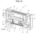
- Fig. 14 shows the arrangement of the control board, etc. in the electrical component chamber 61.
- a control board portion for controlling the electrolytic water generating unit for generating electrolytic water is also arranged in the electrical component chamber 61 (or electrical component box).
- electrical parts generating high heating values are mounted on the control board portion for the electrolytic generating unit, and thus it is preferable to efficiently radiate heat.
- a heat sink may be used as a heat radiating mechanism.
- control boards 152 and 52 for controlling the whole apparatus are arranged in the electrical component chamber 61.
- An electrical part 153 is mounted on one control board 152, and the control board 152 is fixed to the back plate 2F of the housing 2 through screws 156 (see Fig. 15).
- a switching transistor (electrical part) 53A for controlling current supply to the electrodes 32 and 33 is connected to the other control board 52, and the transistor 53A is secured through an insulating sheet 54 to a heat sink 55 for heat radiation.
- the heat sink 55 is formed of aluminum by extrusion molding, and secured to the partition plate 51 through screws 56.
- the heat sink 55 has plural fin members 55A, and an opening 51A having substantially the same outer shape as the assembly of the plural fin members 55A is formed in the partitionplate 51 as shown in Fig. 14.
- the plural finmembers 55A penetrates through the opening 51A and extends to the suction space C between the pre-filter 3A and the support plate 8 at the lower stage of the air filtering chamber 60 so as to face the suction port 7A of the air blowing fan 7 (see Fig. 14).
- the electrical part 53A is an electrical part for controlling the current supply to the electrodes 32 and 33, and the heat generation amount thereof is large. However, according to this construction, the heat radiation amount is increased, and thus the electrical part 53A is sufficiently cooled.
- the heat sink 55 since the heat sink 55 is disposed so as to penetrate through the opening 51A of the partition plate 51, the heat sink 55 may be inserted from the electric component chamber 61 into the air filtering chamber 60 while the electrical part 53A is mounted on the heat sink 55 in advance, and then secured to the partition plate 51 by screws 56. Therefore, the installation of the heat sink 55 can be enhanced.
- ozone (O 3 ), hydrogen peroxide (H 2 O 2 ) or the like may be generated as active oxygen specifies.
- active oxygen specifies can be highly efficiently and stably generated from water containing diluted ion specifies by electrolysis.
- ozone (O 3 ) and hydrogen peroxide (H 2 O 2 ) which have strong sterilizing power are generated by supplying current to the electrodes, and electrolytic water containing ozone (O 3 ) and hydrogen peroxide (H 2 O 2 ) can be created.
- the concentration of ozone or hydrogen peroxide in the electrolytic water is adjusted to a value suitable for inactivate target virus or the like and air is passed through the gas-liquid contact member 5 supplied with the electrolytic water having this concentration, whereby target virus, etc. floating in the air can be inactivated.
- the polarities of the electrodes switching the plus and minus polarities of the electrodes.
- the scale deposited on the cathode can be removed by performing electrolysis while the cathode is used as the anode.
- the polarities of the electrodes maybe inverted periodically by using a timer, or the polarities of the electrodes may be inverted irregularly, for example, every time the operation of the apparatus is started or the like.
- increase of the electrolysis resistance (reduction in electrolysis current or increase in electrolysis voltage) may be detected, and the polarities of the electrodes maybe inverted on the basis of the detection result.
- the above embodiment adopts the water supply system based on the water supply tank 11 which can be freely put in and out.
- the present invention may adopt a water pipe water supply system in which a tap water pipe is connected to the apparatus in place of the water supply tank 11. and city water (tap water) is introduced.
- the water return portion 71 is formed at the end portion 9A of the water receiving tray 9 by bending the end portion of the water receiving tray 9, however, the present invention is not limited to this embodiment.
- a bank may be provided to the end portion 9A of the water receiving tray 9 to prevent flow-back of electrolytic water.
- the above-described embodiments adopt an indoor air circulating system in which indoor air is sucked from a room, subjected to sterile filtration (air filtering treatment) and then returned to the room.
- air to be subjected to sterile filtration is not limited to indoor air, and outdoor air may be directly subjected to sterile filtration and then supplied to the room.
- both indoor air and outdoor air may be subj ected to sterile filtration, and then supplied to the room. That is, any air in-take manner may be adopted.
- the air filtering apparatus is a floor-mount type air filtering apparatus that is used under the state that it is put on the floor.
- the air filtering apparatus of the present invention is not limited to the floor-mount type air filtering apparatus, and it may be used in any condition, for example, in a wall-suspended fashion, in a ceiling-suspended fashion, in a ceiling-cassette fashion or the like.
Landscapes
- Engineering & Computer Science (AREA)
- Chemical & Material Sciences (AREA)
- Combustion & Propulsion (AREA)
- Mechanical Engineering (AREA)
- General Engineering & Computer Science (AREA)
- Life Sciences & Earth Sciences (AREA)
- Health & Medical Sciences (AREA)
- Environmental & Geological Engineering (AREA)
- Epidemiology (AREA)
- Hydrology & Water Resources (AREA)
- Electrochemistry (AREA)
- Water Supply & Treatment (AREA)
- Organic Chemistry (AREA)
- Chemical Kinetics & Catalysis (AREA)
- General Chemical & Material Sciences (AREA)
- Animal Behavior & Ethology (AREA)
- General Health & Medical Sciences (AREA)
- Public Health (AREA)
- Veterinary Medicine (AREA)
- Disinfection, Sterilisation Or Deodorisation Of Air (AREA)
- Water Treatment By Electricity Or Magnetism (AREA)
- Separation Of Particles Using Liquids (AREA)
Abstract
Description
- The present invention relates to a portable air filtering apparatus that can remove (inactivate, sterilize, etc.) microorganisms such as virus, bacteria, fungus, etc. floating in the air, for example, and particularly relates to a portable floor-mount type air filtering apparatus.
- For the purpose of removing microorganisms such as virus, bacteria, fungus, etc. floating in the air, there has been proposed a sterilizing apparatus in which electrolytic water mist is diffused into the air so that the electrolytic water mist is brought into direct contact with microorganisms floating in the air, thereby inactivating the microorganisms such as virus, bacterial, fungus, etc.
- According to this sterilizing apparatus, since the electrolytic water mist is diffused into the air, water containing hypochlorous acid or the like is supplied and infiltrated into a humidifying element formed of non-woven cloth and air blown from an air blower is applied to the humidifying element to thereby discharge moisture of the humidifying element (for example, see
JP-A-2002-181358 - The above-described sterilizing apparatus works effectively under a use environment which electrolytic water mist of mine particles easily reach, that is, in a relatively small space, however, it does not work effectively in a user environment which the electrolytic water mist hardly reaches, that is in a large space such as a kindergarten, an elementary/junior/high school, long-term care insurance facilities, a hospital or the like.
- Therefore, the present invention has been implemented in order to solve the above problem, and a first object of the present invention is to provide a floor-mount type air filtering apparatus that stably perform sterile filtration of air passing through a filter and further can perform sterile filtration of air in a large space.
- A second object of the present invention is to provide a floor-mount type air filtering apparatus that can water-tightly secure a water receiving tray to a partition plate.
- A third object of the present invention is to provide a floor-mount type air filtering apparatus in which a support tray and a circulating pump do not interfere with each other when the support tray is detached.
- A fourth object of the present invention is to provide a floor-mount type air filtering apparatus that can secure the flow rate and amount of air blown from an air blower to a gas-liquid contact member.
- A fifth object of the present invention is to provide a floor-mount type air filtering apparatus that can effectively cool a control board portion for controlling an electrolytic water generating unit, etc.
- In order to attain the above objects, an air filtering apparatus (for example, a floor-mount type air filtering apparatus) according to the present invention comprises: a housing (2); at least one partition plate (51, 52) for partitioning the inside of the housing into at least two chambers (60, 61, 62); a gas-liquid contact member (5) for receiving electrolytic water from an electrolytic water supply unit; an air blowing fan (7) for blowing air to the gas-liquid contact member so that the air is brought into contact with the electrolytic water flowing along the gas-liquid contact member; a controller (52, 53) for controlling the floor-mount type air filtering apparatus; and a water receiving tray (9) for receiving the electrolytic water flowing out from the gas-liquid contact member, wherein the gas-liquid contact member (5) and the air blowing fan (7) are disposed in one (60) of the chambers, and one of the controller and the electrolytic water supply unit is disposed in the other chamber (61 or 62) of the at least two chambers.
- According to the above-described floor-mount type air filtering apparatus, the inside of the housing of the air filtering apparatus is sectioned into plural chambers by at least one partition plate, and one chamber is used as an air filtering chamber for performing sterile filtration while the other chamber is used as an electric-component chamber for accommodating electric component parts or an electrolytic water supply chamber for accommodating the electrolytic water supply unit. Accordingly, the electrolytic water in the air filtering chamber is prevented from spattering into the electric component chamber and further the constituent elements of the floor-mount type air filtering apparatus can be accommodated in the housing in order and in a compact arrangement.
- Furthermore, in the above-described floor-mount type air filtering apparatus, one end portion (9A) of the water receiving tray (9) may penetrate through one partition plate (51) so as to extend to the other chamber (61).
- According to the above construction, the end portion of the water receiving tray penetrates through the partition plate so as to extend to the other chamber side, and thus the water receiving tray can be water-tightly secured to the partition plate without inducing any gap between the partition plate and the water receiving tray. Furthermore, the end portion of the water receiving tray is inserted through an opening portion formed in the partition plate to fix the water receiving tray to the partition plate, and thus the fixing work can be easily performed.
- In the above-described floor-mount type air filtering apparatus, a cover member (72) for covering the end portion (9A) of the water receiving tray (9) may be provided in the other chamber (61).
- Furthermore, antirust coating may be applied to the water receiving tray (9).
- Still furthermore, a water return portion (back board) (71) may be provided to the end portion of the water receiving tray.
- The water receiving tray (9) may be disposed so as to downwardly incline from the other chamber (61) to the one chamber (60).
- Furthermore, the electrolytic water contains active oxygen species achieved by electrolyzing water such as tap water or the like, and the active oxygen specifies contain at least one of hypochlorous acid, ozone and hydrogen peroxide.
- Still furthermore, in the above-described floor-mount type air filtering apparatus, the electrolytic water supply unit may contain a support tray (10) for receiving electrolytic water flowing from the water receiving tray (9) located below the gas-liquid contact member (5) and stocking the electrolytic water concerned, and a circulating pump (13) that is inserted in the support tray and pumps up the electrolytic water stocked in the support tray, wherein one of a projecting portion (50A) and a rail groove (53) in which the projecting portion (50A) is fitted so as to be movable along the rail groove (53) is provided to at least one of both the side surfaces (10c, 10d) of the support tray (10), the other of the projecting portion and the rail groove is provided to at least one of the inner side surface (2Z) of the housing and the side surface (52c) of the partition plate (52), the inner side surface (2Z) and the side surface (52c) facing the side surfaces (10c, 10d) of the support tray (10), and the rail groove (53) is designed so that the projecting portion (50A) is guided along the rail groove (53) and the support tray (10) is prevented from abutting against the circulating pump (13) when the support tray (10) is detached from the housing (2). In this case, the projecting portion (50A) may be downwardly guided along the rail groove (53) until the circulating pump (13) is located at the outside of the support tray (10).
- Furthermore, the rail groove (53) may comprise a vertical movement portion (53b)and a horizontal movement portion (53a) intercommunicating with the vertical movement portion (53b), the support tray (10) being movable in one of a downward direction and an obliquely downward direction and horizontally movable along the horizontal movement portion (53a) and detached from one end of the horizontal movement portion (53a) to the outside of the housing (2) when the support tray (10) is detached from the housing (2) .
- According to the above construction, by moving the projecting portion of the support tray along the rail groove, the support tray can be detached from the housing without interfering with the circulating pump.
- Specifically, the rail groove comprises the horizontal movement portion extending substantially in the horizontal direction from the take-out side of the support tray to the back side of the housing, and the vertical movement portion extending from the back end of the horizontal movement portion upwardly or obliquely upwardly. Therefore, the support tray can be guided along the vertical movement portion downwardly or obliquely downwardly from the state that the support tray is secured to the housing, and further drawn out (taken out) along the horizontal movement portion.
- Accordingly, the rail groove is formed such that the projecting portion is downwardly guided along the rail groove until the circulating pump is located at the outside of the support tray when the support tray is detached from the housing. Therefore, by moving the projecting portion of the support tray along the rail groove, the support tray can be detached from the housing while the support tray and the circulating pump do not interfere with each other.
- Furthermore, the support tray can be guided downwardly or obliquely downwardly along the vertical movement portion from the state that the support tray is secured to the housing. Therefore, by moving the projecting portion of the support tray along the rail groove, the support tray can be detached from the housing while the interference between the support tray and the circulating pump can be more surely prevented. Still furthermore, the support tray can be drawn out to the take-out side along the horizontal movement portion, and thus the support tray can be horizontally drawn out without being inclined.
- The above-described floor-mount type air filtering apparatus may be further equipped with an air guide plate for guiding air from an air blow-out port (7a) of the air blowing fan (7) to the gas-liquid contact member (5). The air guide plate may comprise an extension portion (50a) extending in a flow direction of air blown out from the air blowing fan (7), and a guide portion (50b) that is connected to the extension portion (50a) and extends obliquely from the blow-out port (7a) toward the gas-liquid contact member.
- Furthermore, the floor-mount type air filtering apparatus may be further equipped with a support plate (8) for isolating the gas-liquid contact member and the air blowing fan from each other, and the support plate (8) is provided with an opening (8a) through which the air blown out from the air blowing fan is passed.
- Still furthermore, The inclination angle of the guide portion (50b) is adjustable with respect to the extension portion (50a).
- The length of the extension portion (50a) is adjustable.
- According to the above construction, the air blown out from the air blowing fan is passed through the extension portion, so that the air can be guided to the guide portion without reducing the air flow rate and the air flow amount.
- Furthermore, the gas-liquid contact member and the air blowing fan can be isolated from each other by the support plate, and the opening through which the air blown out from the air blowing fan is passed is formed in the support plate. Therefore, the mount side of the air blowing fan and the mount side of the gas-liquid contact member are isolated from each other by the support plate, so that the air blown out from the air blowing fan is prevented from returning to the air blowing fan side.
- Still furthermore, the inclination angle of the guide portion is adjustable with respect to the extension portion, and thus the air flow direction can be varied in conformity with the shape and size of the gas-liquid contact member and the mount position of the gas-liquid contact member.
- Still furthermore, the length of the extension portion is adjustable, and thus the length of the extension portion can be adjusted so that neither turbulent flow nor eddy occurs in the air stream from the air blowing fan.
- Accordingly, the air blown out from the air blowing fan is temporarily guided by the extension portion of the air guide plate, whereby neither turbulent flow nor eddy occurs in the air stream, and thus the air flow rate and air flow amount of the air blown out from the air blowing fan can be kept with no change. Furthermore, indoor air can be fed from the blow-out port of the air blowing fan to the gas-liquid contact member located at a remote position by the guide portion, whereby the air can be uniformly applied onto the gas-liquid contact member.
- Furthermore, by providing the support plate, the air of the air blowing fan can be prevented from escaping to the air blowing fan side. As a result, the air flow amount of the air fed to the gas-liquid contact member can be increased.
- Still furthermore, by varying the inclination angle of the guide portion, the air flowing direction can be changed in conformity with the size and position of the gas-liquid contact member. Accordingly, air (for example, indoor air) can be evenly applied to the whole gas-liquid contact member.
- Furthermore, by adjusting the length of the extension portion, occurrence of turbulent flow and eddy in air stream can be prevented. Accordingly, the air flow amount and the air flow rate can be prevented from being reduced.
- In the above-described floor-mount type air filtering apparatus, the controller may contain a control board portion having electric parts and a heat sink for the electric parts, and the heat sink may be disposed so as to penetrate through an opening (51) formed in the partition plate (51) and face a suction port (3) of the air blowing fan (7).
- Furthermore, the inside of the housing (2) may be vertically partitioned by one partition plate (51), the suction port (3) of the air blowing fan (7) may be substantially horizontally disposed, and air blown out from the air blowing fan to the gas-liquid contact member (5) is sucked from the suction port (3) that is formed in the housing and located at the lower side of the air blowing fan.
- Furthermore, the electrolytic water supply unit may have electrodes for electrolyzing water to generate electrolytic water and the electric parts may contain a part for controlling electrodes of the electrolytic water supply unit.
- Still furthermore, the electrolytic water generated in the electrolytic water supply unit may be electrolytic water containing active oxygen species achieved by supplying current to the electrodes and electrolyzing tap water.
- Still furthermore, the active oxygen specifies may contain at least one of hypochlorous acid, ozone and hydrogen peroxide.
- According to the above construction, the heat sink of the electrical parts of the control board portion penetrates through the opening formed in the partition plate, and is located so as to face the suction port of the air flowing fan. Therefore, indoor air flows while coming into contact with the heat sink, and then is sucked into the suction port of the air blowing fan. Accordingly, the cooling of the heat sink is promoted, and thus heat radiation of the electrical parts is also promoted. Furthermore, since the heat sink is disposed so as to penetrate through the opening of the partition plate, the heat sink may be inserted from the other chamber into the one chamber while the control board portion is secured to the heat sink in advance, and then secured to the partition plate by screws or the like. Therefore, the work of fixing the heat sink can be enhanced.
-
- Fig. 1 is a perspective view showing an embodiment of a floor-mount type air filtering apparatus according to the present invention;
- Figs. 2A and 2B are perspective views showing the internal construction of the floor-mount type air filtering apparatus;
- Fig. 3 is a longitudinal-sectional view of a housing;
- Fig. 4 is a front view showing a gas-liquid contact member;
- Figs. 5A to 5C are systematic diagrams showing a mechanism for dropping electrolytic water to the gas-liquid contact member, wherein Fig. 5A is a side view of the mechanism, Fig. 5B is a cross-sectional view of a water spray portion (water spray box) and Fig. 5C is a diagram showing the construction of an electrolytic bath;
- Fig. 6 is a perspective view showing the internal construction of the housing;
- Fig. 7 is a perspective view showing a water receiving tray penetrating through a partition plate which is viewed from an electric component chamber;
- Fig. 8 is an exploded perspective view showing a state that the partition plate and the water receiving tray are assembled with each other;
- Fig. 9 is a diagram showing air cleaning;
- Fig. 10 is a perspective view showing a support tray used in the floor-mount type air filtering apparatus of the embodiment;
- Fig. 11 is a perspective view showing a lower portion of a water supply chamber of the floor-mount type air filtering apparatus according to the embodiment;
- Fig. 12 is a perspective view showing a state where the support tray used in the floor-mount type air filtering apparatus of the embodiment is secured to the lower portion of the water supply chamber;
- Fig. 13 is a partially enlarged view showing an
opening portion 8a when the floor-mount type air filtering apparatus shown in Fig. 2 is viewed from the back side; - Fig. 14 is a perspective view showing the internal construction of the floor-mount type air filtering apparatus when a heat sink is provided;
- Fig. 15 is a perspective view showing the arrangement of the heat sink; and
- Fig. 16 is a diagram showing the arrangement of the heat sink.
- Preferred embodiments according to the present invention will be described hereunder with reference to the accompanying drawings.
- In Fig. 1,
reference numeral 1 represents an air filtering apparatus. The following description will be described by representatively using a floor-mount type air filtering apparatus which is used under the state that it is put on the floor, however, the air filtering apparatus is not limited to this type of air filtering apparatus. - The floor-mount type
air filtering apparatus 1 has a box-shapedhousing 2, and thehousing 2 comprisesleg pieces 2A, afront panel 2B and atop panel 2C, and an operatinglid 2D, an opening/closing lid 2E are arranged in a lateral direction at both the sides of thetop panel 2C. - As shown in Fig. 2A, two
partition plates housing 2 is divided into three chambers (anair filtering chamber 60, anelectric component chamber 61 and a water supply chamber 62) by thepartition plates - An
elongated suction port 3 is formed at the lower side of the air filtering chamber (one chamber) 60 formed at the center of thehousing 2, and apre-filter 3A is disposed at the upper side of thesuction port 3. Anair blowing fan 7 is disposed above thepre-filter 3A, and a gas-liquid contact member 5 having high water retentivity is disposed above theair blowing fan 7 so as to be tilted as shown in Fig. 3. Furthermore, awater receiving tray 9 for receiving electrolytic water flowing out from the gas-liquid contact member 5 is disposed below the gas-liquid contact member 5. Thewater receiving tray 9 is designed to have a substantially V-shaped section as shown in Fig. 3. - Furthermore, as shown in Figs. 2A and 2B, an elongated blow-out
port 4 from which blown air passing through the gas-liquid contact member 5 is blown out is formed above the gas-liquid contact member 5.Reference numeral 8 represents a support plate of theair blowing fan 7, and thissupport plate 8 is suspended substantially horizontally between thepartition plates - The
air blowing fan 7 is secured to thesupport plate 8, and anopening portion 8a penetrating through thesupport plate 8 in the vertical direction is formed at the center position (see Fig. 3) in the right and left direction of the gas-liquid contact member 5 on the plane of thesupport plate 8. The air blow-outport 7a of theair blowing fan 7 is disposed so as to face theopening portion 8a, and air blown out from theair blowing fan 7 is upwardly blown out. Theopening portion 8a and the air blow-outport 7a of theair blowing fan 7 are designed to be substantially equal to each other in shape and size. Furthermore, the aperture area of each of the air blow-outport 7a of the air blowing fan and theopening portion 8a is set to be smaller than the horizontal project area of the gas-liquid contact member 5 located above theopening portion 8a. - Electrical parts such as a print board (control board) for controlling the operation of the floor-mount type
air filtering apparatus 1, etc. are accommodated in the electric component chamber (the other chamber) 61 formed at the left side of thehousing 2. In addition, an electrolytic water supply unit comprising a water supply tank support tray (support tray) 10 for stocking electrolytic water received by thewater receiving tray 9, a circulatingpump 13 for pumping up the electrolytic water stocked in thesupport tray 10, an electrolytic bath in which the water pumped by the circulatingpump 13 is electrolyzed to generate electrolytic water, a detachablewater supply tank 11, etc. is disposed in thewater supply chamber 62 formed at the right side of thehousing 2 as shown in Figs. 2A and 2B. Fig. 2A shows a state where thewater supply tank 11 and a part of the water supplytank support tray 10 shown in Fig. 2B are detached. - The gas-
liquid contact member 5 comprises a filter member having a honeycomb structure, and it is designed so that a broad gas-liquid contact area can be secured, electrolytic water can be dropped and clogging occurs hardly. That is, as shown in Fig. 4, the gas-liquid contact member 5 comprises corrugatedraw materials 5A and flat-plate typeraw materials 5B joined to the corrugatedraw materials 5A, and it is designed in a honeycomb structure as a whole. Theseraw materials liquid contact member 5 is preferably set to 30° or more. If the inclination angle θ is less than 30°, dropped electrolytic water does not flow along the slope of the gas-liquid contact member 5, but falls downwardly. On the other hand, if the inclination angle θ approaches to 90°, the air flow passage of the air passing through the gas-liquid contact member 5 is nearly horizontal, and thus it is more difficult to blow out the air upwardly. When the air blow-out direction concerned is set to the horizontal direction, it is impossible to blow out air to a remote place, and thus the apparatus is unsuitable for air filtering in a large space. Accordingly, it is preferable that the inclination angle θ satisfies 80°>θ>30°, and in this embodiment, the inclination angle θ is set to about 40°. - Figs. 5A to 5C show a mechanism for dropping electrolytic water to the gas-
liquid contact member 5. - The
water receiving tray 9 is disposed below the gas-liquid contact member 5 as described above, and the water supply tank support tray (hereinafter referred to as "support tray") 10 intercommunicates with thewater receiving tray 9 or thesupport tray 10 is disposed at the lower side of thewater receiving tray 9. - In this construction, the
water receiving tray 9 is disposed so as to be downwardly inclined to thesupport tray 10, and thus electrolytic water received by thewater receiving tray 9 more easily flows to thesupport tray 10. In this case, thesupport tray 10 is disposed at the downstream side of thewater receiving tray 9. - In this case, the
water supply tank 11 for supplying (supplementing) water containing chlorine ions (for example, tap water) and the circulatingpump 13 are disposed in thesupport tray 10. Theelectrolytic bath 31 of the electrolytic water generating unit is connected to the circulatingpump 13, and an electrolyticwater supply pipe 17 is connected to theelectrolytic bath 31. The electrolyticwater supply pipe 17 has many water spray holes (not shown) on the outer peripheral portion thereof, and it is inserted in a water spray portion (box) 5C formed at the upper edge portion of the gas-liquid contact member 5 as shown in Fig. 5B. - As shown in Fig. 5C, the
electrolytic bath 31 has plural pairs ofelectrodes 32 and 33. By supplying current to theseelectrodes 32 and 33, water flowing into theelectrolytic bath 31 is electrolyzed to generate active oxygen species. Here, the active oxygen species are defined as molecules having higher oxidizing activity than normal oxygen molecules and relating materials, and contain so-called narrowly-defined active oxygen such as superoxide anion, singlet oxygen, hydroxyl radical, hydrogen peroxide, etc. and also so-called broadly-defined active oxygen such as ozone, hypohalous acid, hypochlorous acid, etc. Theelectrolytic bath 31 is disposed in proximity to the gas-liquid contact member 5, and it immediately supply the gas-liquid contact member 5 with active oxygen species generated by electrolyzing water pumped by the circulatingpump 13. - Each of the
electrodes 32 and 33 is an electrode plate comprising a base of Ti (titan) and a coating layer of Ir (iridium), Pt (platinum), and the current value applied to theelectrodes 32, 33 is set to several mA to several tens mA (milliampere) /cm2 (square centimeter) in current density to generate a predetermined free residual chlorine concentration (for example, 1mg (milligram)/l (liter)). - By supplying current to tap water through the
electrodes 32, 33, at the cathode, the following reaction occurs:
4H+ + 4e- + (40H-) → 2H2 + (40H-)
At the anode, the following reaction occurs:
2H2O → 4H+ + O2 + 4e-
At the same time, chlorine ions contained in water (pre-added in tap water) make the following reaction:
2Cl- → Cl2 + 2e-
Furthermore, Cl2 reacts with water as follows:
Cl2 + H2O → HClO + HCl
- In this construction, HClO (hypochlorous acid) having high sterilization power is generated by supplying current to the
electrodes 32, 33, and various microorganisms such as bacteria, virus, etc. can be prevented from breeding in the gas-liquid crystal member 5 by making air pass through the gas-liquid contact member 5 to which electrolytic water containing hypochlorous acid is supplied. Therefore, microorganisms such as virus, bacteria, etc. floating in the air passing through the gas-liquid contact member 5 can be inactivated. Odor also reacts with hypochlorous acid in the electrolytic water when passing through the gas-liquid contact member 5, so that it is ionized and dissolved in the electrolytic water. Therefore, the odor can be removed from the air and thus the air is deodorized. - In order to effectively inactivate microorganisms such as virus, bacteria, etc. floating in the air, it is preferable that the contact area between air and electrolytic water in the gas-
liquid contact member 5 is increased. Therefore, according to this embodiment, from the viewpoint of increasing the contact area, it is preferable that the gas-liquid contact member 5 is disposed so as to extend substantially from end to end in the lateral direction in the compartmented chamber (i.e., the air filtering chamber 60). - Therefore, the
water receiving tray 9 is required to be water-tightly fixed to thepartition plate 51 so that no electrolytic water leaks from the gap between thepartition plate 51 and thewater receiving tray 9. Here, it may be considered that thewater receiving tray 9 and thepartition plate 51 are welded to each other to water-tightly fix thewater receiving tray 9 to thepartition plate 51. However, in the case of the welding work, the welding portion is easily oxidized by electrolytic water and also the welding work is cumbersome. - In order to facilitate the fixing work between the
water receiving tray 9 and thepartition plate 51, it may be also considered that thewater receiving tray 9 disposed below the gas-liquid contact member 5 is disposed so that one end thereof at the electric component chamber (61) side is higher than the other end thereof at the water supply chamber (62) side as shown in Fig. 6 (that is, thewater receiving tray 9 is obliquely downwardly disposed from the electric component chamber side to the water supply chamber side), and also the upper end portion (end portion) 9A of the water receiving tray penetrates through thepartition plate 51 so as to extend to the electric component chamber (61) side so that no electrolytic water leaks downwardly from the gap between thewater receiving tray 9 and thepartition plate 51. - The above constriction will be described hereunder in more detail with reference to Figs. 6 to 8.
- A sponge
type seal member 74 is attached to the back side of thewater receiving tray 9, and anopening 51A having substantially the same shape as the cross-sectional shape of the water receiving tray 9 (containing the seal member 74) (in this embodiment, substantially V-shape) is formed in thepartition plate 51. Theupper end portion 9A of thewater receiving tray 9 is disposed so as to penetrate through theopening 51A of thepartition plate 51 and extend to the electrical component chamber (61) side. - As shown in Fig. 7, a water return portion (throating unit) 71 is formed at the
upper end portion 9A of thewater receiving tray 9. Thewater return portion 71 is formed so as to be bent by folding back the lower edge portion of theupper end portion 9A of thewater receiving tray 9 upwardly, and it prevents electrolytic water stocked in thewater receiving tray 9 from flowing into theelectric component chamber 61. - According to the above construction, the
water receiving tray 9 is disposed so as to be downwardly inclined from theelectric component chamber 61 to theair filtering chamber 60, and thus the electrolytic water in thewater receiving tray 9 is prevented from flowing back. Even when electrolytic water is trapped in thewater receiving tray 9, the electrolytic water can be prevented from invading into theelectric component chamber 61 by thewater return portion 7 formed at theupper end portion 9A of thewater receiving tray 9. - Furthermore, according to the above construction, when the floor-mount type air filtering apparatus is fabricated, the
water receiving tray 9 is inserted from theelectric component chamber 61 through theopening 51A of thepartition plate 51 to theair filtering chamber 60, and then the other end portion of thewater receiving tray 9 is inserted through anopening 52A formed in thepartition plate 52 so as to extend to thewater supply chamber 62 side as shown in Fig. 8, whereby thewater receiving tray 9 is secured to thepartition plates - Furthermore, as shown in Figs. 6 to 8, a
cover member 72 covering theupper end portion 9A of thewater receiving tray 9 may be fixed at one side surface of thepartition plate 51 which faces the electrical component chamber (61) side. Thiscover member 72 is provided with fixingpieces cover member 72 respectively, and fixingholes 73 are formed in these fixingpieces partition plate 51, and thecover member 72 is fixed by screws 75 (see Fig. 8). Thecover member 72 prevents air containing electrolytic water from invading from theair filtering chamber 60 through theopening 51A into theelectrical component chamber 61. - Furthermore, the surfaces of the
water receiving tray 9, thepartition plate 51 and thepartition plate 52 are subjected to antirust coating such as cation coating or the like. In general, hypochlorous acid has a property of oxidizing and rusting metal such as iron, etc. Therefore, according to the above construction, the antirust coating is applied to the surface of thewater receiving tray 9 receiving electrolytic water at all times and the surfaces of thepartition plates water receiving tray 9, thereby preventing occurrence of rust in thewater receiving tray 9 and thepartition plates - Still furthermore, according to this embodiment, as described above, the
water receiving tray 9 is secured to thepartition plates water receiving tray 9 into theopenings water receiving tray 9 and thepartition plates water receiving tray 9 and thepartition plates water receiving tray 9 and thepartition plates - Next, the operation of the floor-mount type air filtering apparatus of this embodiment will be described.
- In Fig. 1, when the operating
lid 2D is opened, an operation panel (not shown) is exposed. By operating this operation panel, the operation of the floor-mount typeair filtering apparatus 1 is started. When this operation is started, the circulatingpump 13 is driven, and water (for example, tap water) stocked in thesupport tray 10 is supplied to theelectrolytic bath 31. - In this
electrolytic bath 31, the water is electrolyzed by supplying current to theelectrodes 32 and 33 to generate electrolytic water containing active oxygen specifies. This electrolytic water is passed through the spray holes (not shown) of the electrolyticwater supply pipe 17, and sprayed into the water spray portion (box) 5C. The electrolytic water thus sprayed infiltrates into the upper edge portion of the gas-liquid contact member 5 and gradually diffuse to the lower portion of the gas-liquid contact member 5. - Surplus electrolytic water is collected in the
water receiving tray 9, flows to theadjacent support tray 10 and then is stocked there. In this construction, the water supply system is a circulating system, and when the amount of water is reduced due to vaporization or the like, a suitable amount of water (tap water or the like) is supplemented through thewater supply tank 11 into thesupport tray 10. When the amount of water in thewater supply tank 11 is reduced, the opening/closing lid 2E (see Fig. 1) is opened, and thewater supply tank 11 is taken out to supplement water (tap water or the like) into thewater supply tank 11. - Indoor air is supplied through the
air blowing fan 7 to the gas-liquid contact member 5 filled with the electrolytic water as indicated by an arrow X (see Fig. 3). The indoor air is brought into contact with the active oxygen specifies of the electrolytic water infiltrating in the gas-liquid contact member 5 and then blown out to the room again. For example, when influenza virus inducing infection is floated in the indoor air, the active oxygen species has a function of breaking and vanishing (removing) the surface proteins of the virus. When influenza virus is broken, the influenza virus is not bonded to a receptor which is required for the influenza virus to infect, and thus the infection can be prevented. As a demonstration test result, it has been found that when air having influenza virus floated therein is passed through the gas-liquid contact member 5 of this embodiment, 99% or more of influenza virus can be removed (inactivated). - In this embodiment, the inside of the floor-
mount type housing 2 is divided into theair filtering chamber 60 and the electric component chamber 61 (and/or the water supply unit 62) by the partition plate 51 (and/or the partition plate 52), and the gas-liquid contact member 5 which is disposed substantially from end to end in the lateral direction and supplied with electrolytic water from theelectrolytic bath 31, and theair blowing fan 7 for blowing indoor air to the gas-liquid contact member 5 are provided in theair filtering chamber 60. Furthermore, the controller for controlling theair blowing fan 7, theelectrolytic bath 31, etc. is provided in theelectronic component chamber 61. Furthermore, thewater receiving tray 9 for receiving electrolytic water flowing out from the gas-liquid contact member 5 is disposed below the gas-liquid contact member 5, and theend portion 9A of thewater receiving tray 9 penetrates through thepartition plate 51 and extends to theelectric component chamber 61. Therefore, no gap occurs between thepartition plate 51 and thewater receiving tray 9, and thewater receiving tray 9 can be water-tightly secured to thepartition plate 51. Furthermore, according to this embodiment, thewater receiving tray 9 is inserted into theopening 51A formed in thepartition plate 51 and secured to thepartition plate 51, and thus it is unnecessary to carry out a welding work or screw clamping work, and thus thewater receiving tray 9 can be simply secured to thepartition plate 51. - In this embodiment, the
cover member 72 covering theend portion 9A of thewater receiving tray 9 is secured to the electric component chamber (61) side of thepartition plate 51, and thus air containing electrolytic water is prevented from flowing from theair filtering chamber 60 through theopening 51A of thepartition plate 51 into theelectric component chamber 61. Therefore occurrence of rust in the electrical parts in theelectrical component chamber 61 can be prevented. Furthermore, according to this embodiment, the surface of thewater receiving tray 9 and the surface of thepartition plate 51 are subjected to antirust coating such as cation coating or the like, and thus occurrence of rust in thewater receiving tray 9 receiving electrolytic water at all times and thepartition plate 51 adjacent to thewater receiving tray 9 can be prevented. - Furthermore, according to this embodiment, indoor air sucked from the
suction port 3 provided at the lower portion of thehousing 2 is brought into contact with electrolytic water dropped to the gas-liquid contact member 5, and then blown out from the air blow-outport 4 provided at the upper portion of thehousing 2. Therefore, even when the floor-mount typeair filtering apparatus 1 is set up in a so-called large space such as a kindergarten, an elementary/junior/high school, long-term care insurance facilities, a hospital or the like, indoor air which has been brought into contact with electrolytic water and thus subjected to sterile filtration can be blown out to a remote place in a large space, so that the air filtering operation in a large space can be effectively performed. - Still furthermore, according to this embodiment, electrolytic water containing hypochlorous acid, etc. is collected in the
water receiving tray 9, and flows to theadjacent support tray 10. Therefore, no microorganism occurs in each tray and thus occurrence of slime is prevented. Accordingly, the cleaning and maintenance frequency of each tray can be reduced, and the labor of maintenance, etc. can be reduced. - In the above construction, it is desirable to adjust the concentration of active oxygen species (hypochlorous acid) in electrolytic water to a target concentration. The target concentration is normally set to a value enough to inactivate microorganisms such as virus, bacteria, fungus, etc. which frequently exist in a set-up place of the floor-mount type air filtering apparatus (for example, school). In this case, the concentration of the active oxygen specifies (for example, hypochlorous acid) in the electrolytic water can he adjusted by changing the current flowing through the
electrodes 32 and 33 or the voltage applied between theelectrodes 32 and 33. For example, by increasing the current flowing through theelectrodes 32 and 33 (for example, 40mA/cm2 in current density), the concentration of hypochlorous acid can be changed to a high value. Accordingly, the concentration of active oxygen species can be changed by merely adjusting the voltage applied to the electrodes or adjusting the current flowing through the electrodes without using any new device, and thus the cost can be reduced and the space can be saved. - Here, condensed materials filtered from air by electrolytic water is precipitated at the bottom portion of the support tray, and thus it is preferable to periodically detach the support tray from the air filtering apparatus and clean the support tray. However, the circulating
pump 13 is inserted in the support tray as shown in Fig. 5A, and thus when the support tray is drawn out from the inside of the housing to the front side of the air filtering apparatus, the support tray and the circulating pump interfere with each other. Therefore, the support tray is not smoothly detached from the housing. In order to smoothly detach thesupport tray 10 from the air filtering apparatus, the following construction may be adopted. - Fig. 10 is a perspective view showing a
support tray 10. - The
support tray 10 is formed of foamed material, and designed to have a substantially rectangular parallelepiped outer shape. Thesupport tray 10 is designed to be hollow, and has an opened upper surface. Furthermore, the inside of thesupport tray 10 is divided into right and left spaces by apartition wall 10a. The circulatingpup 13 is inserted in thesupport tray 10 so that thewater suction port 13a of the circulatingpump 13 is located in the left space, and also thewater supply tank 11 is supported in the right space. Thepartition wall 10a has agroove 10b formed at the center portion thereof, and electrolytic water freely flows in the right-and-left direction. - A projecting
portion 50A is provided at the lower portion of the back side of theright surface portion 10c of thesupport tray 10, and also asupport tag 51 is provided at the lower portion of the front side of the rightside surface portion 10c so that the flat portions thereof face in the vertical direction. The projectingportion 50A and thesupport tag 51 project outwardly from theright surface portion 10c, and they are formed integrally with thesupport tray 10 in the plastic foam molding process. Furthermore, the projectingportion 50A and thesupport tag 51 may be also provided to theleft surface portion 10d of thesupport tray 10 so as to be symmetric with those of theright surface portion 10c. - Fig. 11 is a perspective view showing a lower portion of the
water supply chamber 62 to which thesupport tray 10 is secured. In thewater supply chamber 62, the left surface (wall) 52c of thewater supply chamber 62 is formed by thepartition plate 62, and the right side surface (wall) 2Z of thewater supply chamber 62 is formed by theside plate 2X of thehousing 2. A pair ofguide plates 52A for guiding thesupport tray 10 when thesupport tray 10 is attached to or detached from thehousing 2 are provided on both the wall surfaces 52c and 2Z. With respect to theguide plates 52, only oneguide plate 52 may be provided to one of the wall surfaces 52c and 2Z. Arail groove 53 to which the projectingportion 50A of thesupport tray 10 is fitted and a holdinggroove 54 to which thesupport tag 51 of thesupport tray 10 is fitted are formed in theguide plate 52. - The
rail groove 53 comprises ahorizontal movement portion 53a extending horizontally from thesurface portion 2Y of thehousing 2 in the backward direction of the housing, avertical movement portion 53b extending upwardly or obliquely upwardly from the back-side end portion of thehorizontal movement portion 53a to the back side of the housing, and a fixinggroove portion 53c which slightly extends horizontally from the upper end portion of thevertical movement portion 53b in the backward direction of the housing. - The holding
groove 54 is located substantially at the same height as the fixinggroove portion 53c, and extends horizontally from thesurface portion 2Y of thehousing 2 in the backward direction. - Next, the operation of the floor-mount type air filtering apparatus having the
support tray 10 shown in Fig. 10 will be described. - Under the state that the
support tray 10 is mounted in thehousing 2, the circulatingpump 13 and thewater supply tank 11 are inserted in thesupport tray 10 as shown in Fig. 5A. Furthermore, as shown in Fig. 12, when thesupport tray 10 is mounted in thewater supply chamber 62 of thehousing 2, the projectingportion 50A is fitted in the fixinggroove portion 53c of therail groove 53, and thesupport tag 51 is fitted in the holdinggroove 54. - When the
support tray 10 is detached from the above state, thesupport tray 10 is first horizontally drawn out to thesurface portion 2Y side of thehousing 2 to release the engagement between thesupport tag 51 and the holdinggroove 54. This horizontal movement distance is set so that the inner wall of thesupport tray 10 and each of the circulatingpump 13 and thewater supply tank 11 does not interfere with each other. - After the engagement between the
support tag 51 and the holdinggroove 54 is released, thesupport tray 10 is obliquely downwardly moved while keeping thesupport tray 10 in a horizontal position. At this time, the projecting portion of thesupport tray 10 is guided along the extending direction of thevertical movement portion 53b, whereby thesupport tray 10 is obliquely downwardly moved along a fixed passage. The shape of thesupport tray 10 and the moving passage of thesupport tray 10 are determined so that the inner wall of the back side of thesupport tray 10 and each of the circulatingpump 13 and thewater supply tank 11 do not interfere with each other. Thesupport tray 10 is moved until the circulatingpump 13 and thewater supply tank 11 are located at the outside of thesupport tray 10 under the state that thesupport tray 10 is guided to the lower end of thevertical movement portion 53b. - Finally, the
support tray 10 is horizontally drawn out to thesurface portion 2Y side of thehousing 2 while keeping thesupport tray 10 horizontally. At this time, the projectingportion 50A of thesupport tray 10 is guided along the extending direction of thehorizontal movement portion 53a, whereby thesupport tray 10 is horizontally moved. Then, the projectingportion 50A is detached from anopen portion 53 of therail groove 53, thereby detaching thesupport tray 10 from thehousing 2. - When the
support tray 10 is mounted in thehousing 2, thesupport tray 10 is moved in the reverse way to mount thesupport tray 10 in the housing so that thesupport tray 10 and each of the circulatingpump 13 and thewater supply tank 11 do not interfere with each other. - According to the floor-mount type air filtering apparatus, the
rail groove 53 is designed so that the projectingportion 50 is guided downwardly along therail groove 53 until the circulatingpump 13 is located at the outside of thesupport tray 10 when thesupport tray 10 is detached from the inside of thehousing 2. Accordingly, by moving the projectingportion 50 of thesupport tray 10 along therail groove 53, the support tray can be detached while the projectingportion 50 of thesupport tray 10 and the circulatingpump 13 do not interfere with each other. - Furthermore, the
support tray 10 is obliquely downwardly guided along thevertical movement portion 53b from the state that thesupport tray 10 is mounted in the housing Therefore, by moving the projectingportion 50 of thesupport tray 10 along therail groove 53, thesupport tray 10 can be detached so that thesupport tray 10 and the circulatingpump 13 do not interfere with each other. Furthermore, thesupport tray 10 can be drawn out to the take-out side along thehorizontal movement portion 53b, and thus thesupport tray 10 can be horizontally drawn out without thesupport tray 10 being inclined. - In the above construction, the projecting
portion 50 is provided to thesupport tray 10, and therail groove 53 is provided to the housing 2 (partition plate 62) side. However, therail groove 53 may be provided to thesupport tray 10 while the projectingportion 50 is provided to the housing 2 (partition plate 62) side. Accordingly, thesupport tray 10 can be detached while thesupport tray 10 and the circulatingpup 13 do not interfere with each other. - Furthermore, the
vertical movement portion 53b is formed so as to be inclined, however, it may be formed so as to be vertical. Accordingly, thesupport tray 10 can be detached so that thesupport tray 10 and the circulatingpup 13 do not interfere with each other. - Still furthermore, it is preferable in the floor-mount type air filtering apparatus that indoor air blown out from the air blowing fan is evenly applied to the whole of the gas-liquid contact member. In order to satisfy this condition, the air blowing fan may be designed to have an air blowing port having the same outer shape as the gas-liquid contact member. However, the air blowing fan whose air blowing port has a large aperture area as described above needs a large set-up space, and thus it makes it difficult to miniaturize the air filtering apparatus.
- Fig. 13 shows a floor-mount type air filtering apparatus having a mechanism for enabling indoor air blown out from the air blowing fan to be evenly applied to the whole of the gas-liquid contact member all over without increasing the scale of the air filtering apparatus, and corresponds to a back side view of the floor-mount air filtering apparatus of Fig. 2. In Fig. 13, the view of the
opening portion 8a is enlarged. - As shown in Figs. 3 and 13, a pair of
air guide plates 50 may be provided at theopening portion 8a so as to be symmetrically disposed in the right-and-left direction in Fig. 13. The lower side end portions of theair guide plates 50 are fixed to thesupport plate 8. Eachair guide plate 50 comprises anextension portion 50a extending upwardly from the lower end portion thereof, and aguide portion 50b extending obliquely upwardly from the upper end portion of theextension portion 50a toward the gas-liquid contact member 5 located at a remote place from theair blowing fan 7. Theextension portion 50A and theguide portion 50b of theair guide plate 50 are formed integrally with each other by folding sheet metal. - In this case, air blown out upwardly from the air blow-out
port 7a of theair blowing fan 7 is further upwardly blown out from theopening portion 8a of thesupport plate 8, and upwardly guided along theextension portion 50a of theair guide plate 50. At this time, the air blown out along theextension portion 50a is upwardly guided with no occurrence of turbulent flow or eddy and also without reducing the air flow rate and the air flow amount. - The air guided along the
extension portion 50a is further guided along the inclination of theguide portion 50b toward the gas-liquid contact member 5 located at a remote place from theair blowing port 7a of theair blowing fan 7. - Here, an experiment result confirming the effect of the air guide plate will be described.
- When air was blown from the
air blowing fan 7 at an air flow rate of about 3.5m/sec to 3.8m/sec under the state that noair guide plate 50 was provided, the air flow rate at the gas-liquid contact member 5 located at the outside of theair blowing port 7a of theair blowing fan 7 was equal to about 0.3m/s to 0.4m/sec. - Next, when air was blown from the
air blowing fan 7 at an air flow rate of about 3.5m/sec to 3.8m/sec under the state that noextension portion 50a was provided to theair guide plate 50, the air flow rate at the gas-liquid contact member 5 located at the outside of theair blowing port 7a of theair blow fan 7 was equal to 1m/sec or less. - On the other hand, when air was blown out from the
air blowing fan 7 at an air flow rate of about 3.5m/sec to 3. 8m/sec under the state that theextension portion 50a was provided to theair guide plate 50, the air flow rate at the gas-liquid contact member 5 located at the outside of theair blowing port 7a of theair blowing fan 7 exceeded 1m/sec. Furthermore, the air flow rate at the center portion which was not displaced from theopening portion 7a of theair blowing fan 7 was kept to about 3.5m/sec to 3.8m/sec. - According to the floor-mount type air filtering apparatus of this embodiment, air blown out upwardly from the
air blowing port 7a of theair blowing fan 7 is upwardly guided toward the gas-liquid contact member 5 by the air guide plates, whereby neither turbulent flow nor eddy occurs in the air stream and also the air flow rate and the air flow amount of the air blown out from theair blowing fan 7 can be secured. Furthermore, by providing theguide portion 50b, the air can be fed from theair blowing port 7a of theair blowing fan 7 toward the gas-liquid contact member 5 located at a remote place. - In the above-described embodiment, the
extension portion 50A and theguide portion 50b of theair guide plate 50 are formed integrally with each other. However, they may be formed separately from each other. In this case, they are detachably assembled with each other by screws or the like. Furthermore, a plurality ofguide portions 50b which are different in inclination angle may be prepared and selectively used, so that the inclination angle of theair guide plate 50 being used can be freely adjusted. Accordingly, the flow direction of air to be blown to the gas-liquid contact member 5 can be adjusted. - Furthermore, the position of the
guide portion 50b may be designed to be slidable in the vertical direction, so that the vertical length of theextension portion 50a can be increased. Accordingly, the flow direction of air to be blown to the gas-liquid contact member 5 can be also adjusted. - As described above, the
electrical component chamber 61 is water-tightly formed by the partition plate (partition member) 51, and a control board for controlling the whole of the apparatus, etc. are accommodated in theelectrical component chamber 61. Fig. 14 shows the arrangement of the control board, etc. in theelectrical component chamber 61. A control board portion for controlling the electrolytic water generating unit for generating electrolytic water is also arranged in the electrical component chamber 61 (or electrical component box). In this case, electrical parts generating high heating values are mounted on the control board portion for the electrolytic generating unit, and thus it is preferable to efficiently radiate heat. In order to radiate heat from the control board portion as described above, a heat sink may be used as a heat radiating mechanism. - The heat radiating mechanism will be described in detail with respect to Figs. 14 to 16.
- As shown in Fig. 14,
control boards electrical component chamber 61. Anelectrical part 153 is mounted on onecontrol board 152, and thecontrol board 152 is fixed to theback plate 2F of thehousing 2 through screws 156 (see Fig. 15). Furthermore, as shown in Fig. 16, a switching transistor (electrical part) 53A for controlling current supply to theelectrodes 32 and 33 is connected to theother control board 52, and thetransistor 53A is secured through an insulatingsheet 54 to aheat sink 55 for heat radiation. Theheat sink 55 is formed of aluminum by extrusion molding, and secured to thepartition plate 51 throughscrews 56. - The
heat sink 55 hasplural fin members 55A, and anopening 51A having substantially the same outer shape as the assembly of theplural fin members 55A is formed in thepartitionplate 51 as shown in Fig. 14. Theplural finmembers 55A penetrates through theopening 51A and extends to the suction space C between the pre-filter 3A and thesupport plate 8 at the lower stage of theair filtering chamber 60 so as to face thesuction port 7A of the air blowing fan 7 (see Fig. 14). - According to this construction, indoor air flows in the suction space C while coming into contact with the
fins 55A of theheat sink 55, and then sucked into thesuction port 7A of theair blowing fan 7. This air passes and flows between therespective fin members 55A, whereby the cooling of theheat sink 55 is promoted and the heat radiation of theelectrical part 53A is particularly promoted. Theelectrical part 53A is an electrical part for controlling the current supply to theelectrodes 32 and 33, and the heat generation amount thereof is large. However, according to this construction, the heat radiation amount is increased, and thus theelectrical part 53A is sufficiently cooled. Furthermore, since theheat sink 55 is disposed so as to penetrate through theopening 51A of thepartition plate 51, theheat sink 55 may be inserted from theelectric component chamber 61 into theair filtering chamber 60 while theelectrical part 53A is mounted on theheat sink 55 in advance, and then secured to thepartition plate 51 byscrews 56. Therefore, the installation of theheat sink 55 can be enhanced. - The present invention is not limited to the above embodiments, and various modifications may be made without departing from the subject matter of the present invention. For example, ozone (O3), hydrogen peroxide (H2O2) or the like may be generated as active oxygen specifies. In this case, when platinum tantalum electrodes are used as the
electrodes 32 and 33, active oxygen specifies can be highly efficiently and stably generated from water containing diluted ion specifies by electrolysis. - At this time, at the anode, the following reaction occurs:
2H2O → 4H+ + O2 + 4e-
Simultaneously with the above reaction, the following reactions occur, and ozone (O3) is generated.
3H2O → O3 + 6H+ + 6e-
2H2O → O3 + 4H+ + 4e-
Furthermore, at the cathode, the following reactions occur:
4H+ + 4e- + (40H-) → 2H2 + (40H-)
O2 - + e- + 2H+ → H2O2
That is, O2 - generated through the electrode reaction and H+ in solution are bonded to each other to generate hydrogen peroxide (H2O2). - In this construction, ozone (O3) and hydrogen peroxide (H2O2) which have strong sterilizing power are generated by supplying current to the electrodes, and electrolytic water containing ozone (O3) and hydrogen peroxide (H2O2) can be created. The concentration of ozone or hydrogen peroxide in the electrolytic water is adjusted to a value suitable for inactivate target virus or the like and air is passed through the gas-
liquid contact member 5 supplied with the electrolytic water having this concentration, whereby target virus, etc. floating in the air can be inactivated. Furthermore, even odor reacts with ozone or hydrogen peroxide in the electrolytic water when passing through the gas-liquid contact member 5, and ionized and dissolved in the electrolytic water, whereby the odor components are removed from the air and thus the air is deodorized. - When scale is deposited on the electrode (cathode) due to electrolysis of tap water, it is difficult to continue the electrolysis because the electrical conductivity is lowered.
- In this case, it is effective to invert the polarities of the electrodes (switching the plus and minus polarities of the electrodes). The scale deposited on the cathode can be removed by performing electrolysis while the cathode is used as the anode. Under the polarity inverting control, the polarities of the electrodes maybe inverted periodically by using a timer, or the polarities of the electrodes may be inverted irregularly, for example, every time the operation of the apparatus is started or the like. Furthermore, increase of the electrolysis resistance (reduction in electrolysis current or increase in electrolysis voltage) may be detected, and the polarities of the electrodes maybe inverted on the basis of the detection result.
- The above embodiment adopts the water supply system based on the
water supply tank 11 which can be freely put in and out. However, the present invention may adopt a water pipe water supply system in which a tap water pipe is connected to the apparatus in place of thewater supply tank 11. and city water (tap water) is introduced. - Furthermore, in the above embodiment, the
water return portion 71 is formed at theend portion 9A of thewater receiving tray 9 by bending the end portion of thewater receiving tray 9, however, the present invention is not limited to this embodiment. For example, a bank may be provided to theend portion 9A of thewater receiving tray 9 to prevent flow-back of electrolytic water. - Still furthermore, the above-described embodiments adopt an indoor air circulating system in which indoor air is sucked from a room, subjected to sterile filtration (air filtering treatment) and then returned to the room. However, air to be subjected to sterile filtration is not limited to indoor air, and outdoor air may be directly subjected to sterile filtration and then supplied to the room. Furthermore, both indoor air and outdoor air may be subj ected to sterile filtration, and then supplied to the room. That is, any air in-take manner may be adopted.
- Still furthermore, the above-described embodiments, the air filtering apparatus is a floor-mount type air filtering apparatus that is used under the state that it is put on the floor. However, the air filtering apparatus of the present invention is not limited to the floor-mount type air filtering apparatus, and it may be used in any condition, for example, in a wall-suspended fashion, in a ceiling-suspended fashion, in a ceiling-cassette fashion or the like.
Claims (18)
- An air filtering apparatus according to the present invention comprises:a housing (2);at least one partition plate (51, 52) for partitioning the inside of the housing into at least two chambers (60, 61, 62);a gas-liquid contact member (5) for receiving electrolytic water from an electrolytic water supply unit;an air blowing fan (7) for blowing air to the gas-liquid contact member so that the air is brought into contact with the electrolytic water flowing along the gas-liquid contact member;a controller (52, 53) for controlling the floor-mount type air filtering apparatus; anda water receiving tray (9) for receiving the electrolytic water flowing out from the gas-liquid contact member, wherein the gas-liquid contact member (5) and the air blowing fan (7) are disposed in one of the chambers, and one of the controller and the electrolytic water supply unit is disposed in the other chamber of the at least two chambers.
- The air filtering apparatus according to claim 1, wherein one end portion (9A) of the water receiving tray (9) penetrates through one partition plate (51) so as to extend to the other chamber (61).
- The air filtering apparatus according to claim 2, wherein a cover member (72) for covering the end portion (9A) of the water receiving tray (9) is provided in the other chamber (61).
- The air filtering apparatus according to claim 2, wherein antirust coating is applied to the water receiving tray (9).
- The air filtering apparatus according to claim 2, wherein a water return portion (71) is provided to the end portion of the water receiving tray.
- The air filtering apparatus according to claim 2, wherein the water receiving tray (9) is disposed so as to downwardly incline from the other chamber (61) to the one chamber (60) .
- The air filtering apparatus according to claim 1, wherein the electrolytic water contains active oxygen species achieved by electrolyzing water such as tap water or the like, and the active oxygen specifies contain at least one of hypochlorous acid, ozone and hydrogen peroxide.
- The air filtering apparatus according to claim 1, wherein the electrolytic water supply unit contains a support tray (10) for receiving electrolytic water flowing from the water receiving tray (9) located below the gas-liquid contact member (5) and stocking the electrolytic water concerned, and a circulating pump (13) that is inserted in the support tray and pumps up the electrolytic water stocked in the support tray, wherein one of a projecting portion (50A) and a rail groove (53) in which the projecting portion (50A) is fitted so as to be movable along the rail groove (53) is provided to at least one of both the side surfaces (10c, 10d) of the support tray (10), the other of the projecting portion and the rail groove is provided to at least one of the inner side surface (2Z) of the housing and the side surface (52c) of the partition plate (52), the inner side surface (2Z) and the side surface (52c) facing the side surfaces (10c, 10d) of the support tray (10), and the rail groove (53) is designed so that the projecting portion (50A) is downwardly guided along the rail groove (53) until the circulating pump (13) is located at the outside of the support tray (10).
- The air filtering apparatus according to claim 8, wherein the rail groove (53) comprises a vertical movement portion (53b) and a horizontal movement portion (53a) intercommunicating with the vertical movement portion (53b), the support tray (10) being movable in one of a downward direction and an obliquely downward direction and horizontally movable along the horizontal movement portion (53a) and detachable from one end of the horizontal movement portion (53a) to the outside of the housing (2) when the support tray (10) is detached from the housing (2).
- The air filtering apparatus according to claim 1, further comprising an air guide plate for guiding air from an air blow-out port (7a) of the air blowing fan (7) to the gas-liquid contact member (5), wherein the air guide plate comprises an extension portion (50a) extending in a flow direction of air blown out from the air blowing fan (7), and a guide portion (50b) that is connected to the extension portion (50a) and extends obliquely from the blow-out port (7a) toward the gas-liquid contact member.
- The air filtering apparatus according to claim 10 further comprising a support plate (8) for isolating the gas-liquid contact member and the air blowing fan from each other, wherein the support plate (8) is provided with an opening (8a) through which the air blown out from the air blowing fan is passed.
- The air filtering apparatus according to claim 10, wherein the inclination angle of the guide portion (50b) is adjustable with respect to the extension portion (50a).
- The air filtering apparatus according to claim 10, wherein the length of the extension portion (50a) is adjustable.
- The air filtering apparatus according to claim 1, wherein the controller contains a control board portion having electric parts and a heat sink for the electric parts, and the heat sink may be disposed so as to penetrate through an opening (51) formed in the partition plate (51) and face a suction port (3) of the air blowing fan (7).
- The air filtering apparatus according to claim 14, wherein the inside of the housing (2) is vertically partitioned by one partition plate (51), the suction port (3) of the air blowing fan (7) may be substantially horizontally disposed, and air blown out from the air blowing fan to the gas-liquid contact member (5) is sucked from the suction port (3) that is formed in the housing and located at the lower side of the air blowing fan.
- The air filtering apparatus according to claim 14, wherein the electrolytic water supply unit has electrodes for electrolyzing water to generate electrolytic water and the electric parts contain a part for controlling the electrodes of the electrolytic water supply unit.
- The air filtering apparatus according to claim 14, wherein the electrolytic water generated in the electrolytic water supply unit is electrolytic water containing active oxygen species achieved by supplying current to the electrodes and electrolyzing tap water.
- The air filtering apparatus according to claim 17, wherein the active oxygen specifies contain at least one of hypochlorous acid, ozone and hydrogen peroxide.
Applications Claiming Priority (4)
| Application Number | Priority Date | Filing Date | Title |
|---|---|---|---|
| JP2005377733A JP4663520B2 (en) | 2005-12-28 | 2005-12-28 | Floor-standing air sanitizer |
| JP2005377602A JP4663518B2 (en) | 2005-12-28 | 2005-12-28 | Floor-standing air sanitizer |
| JP2005377603A JP4663519B2 (en) | 2005-12-28 | 2005-12-28 | Floor-standing air sanitizer |
| JP2005377511A JP4675230B2 (en) | 2005-12-28 | 2005-12-28 | Floor-standing air sanitizer |
Publications (2)
| Publication Number | Publication Date |
|---|---|
| EP1803471A1 true EP1803471A1 (en) | 2007-07-04 |
| EP1803471B1 EP1803471B1 (en) | 2011-09-07 |
Family
ID=37904361
Family Applications (1)
| Application Number | Title | Priority Date | Filing Date |
|---|---|---|---|
| EP06025987A Not-in-force EP1803471B1 (en) | 2005-12-28 | 2006-12-14 | Air filtering apparatus |
Country Status (3)
| Country | Link |
|---|---|
| EP (1) | EP1803471B1 (en) |
| KR (1) | KR100803907B1 (en) |
| MY (1) | MY149423A (en) |
Cited By (2)
| Publication number | Priority date | Publication date | Assignee | Title |
|---|---|---|---|---|
| WO2010090418A3 (en) * | 2009-02-09 | 2010-12-02 | (주)이화프레지니우스카비 | Filter device and syringe incorporating same |
| EP3309467A4 (en) * | 2015-06-09 | 2019-05-08 | Seung Ho Tak | COOLING APPARATUS FOR REMOVING FUNGI PRESENT ON A SOIL-CONDENSING MODULE WITH HYDROGEN GENERATED BY WATER ELECTROLYSIS CONDENSED AT THE COOLING UNIT DEDUCTION MODULE |
Families Citing this family (3)
| Publication number | Priority date | Publication date | Assignee | Title |
|---|---|---|---|---|
| CN107726448A (en) * | 2017-09-11 | 2018-02-23 | 重庆依凯科技有限公司 | A kind of air purifier simple in construction |
| US11624514B2 (en) * | 2019-02-03 | 2023-04-11 | Gd Midea Air-Conditioning Equipment Co., Ltd. | Window air conditioner with water receiving pan and filter screen support |
| CN113834138A (en) * | 2021-10-19 | 2021-12-24 | 珠海格力电器股份有限公司 | Water retaining and air guiding device and refrigeration equipment |
Citations (3)
| Publication number | Priority date | Publication date | Assignee | Title |
|---|---|---|---|---|
| JP2002181358A (en) * | 2000-10-04 | 2002-06-26 | Denso Corp | Humidifier and air conditioner with humidifier |
| JP2002349913A (en) * | 2001-05-28 | 2002-12-04 | Sanyo Electric Co Ltd | Humidifier |
| EP1619451A1 (en) * | 2004-07-21 | 2006-01-25 | Sanyo Electric Co., Ltd. | Humidifier |
Family Cites Families (4)
| Publication number | Priority date | Publication date | Assignee | Title |
|---|---|---|---|---|
| JP2005013714A (en) | 2004-05-07 | 2005-01-20 | Tatsuo Okazaki | Method and apparatus for indoor spatial sterilization |
| JP4878821B2 (en) | 2005-11-29 | 2012-02-15 | 三洋電機株式会社 | Floor-standing air sanitizer |
| JP4878820B2 (en) | 2005-11-18 | 2012-02-15 | 三洋電機株式会社 | Floor-standing air sanitizer |
| KR20050115216A (en) * | 2005-11-22 | 2005-12-07 | 박병인 | Agricultural pruducts storage house humidification system |
-
2006
- 2006-12-14 EP EP06025987A patent/EP1803471B1/en not_active Not-in-force
- 2006-12-27 KR KR1020060134552A patent/KR100803907B1/en not_active Expired - Fee Related
- 2006-12-27 MY MYPI20064776A patent/MY149423A/en unknown
Patent Citations (3)
| Publication number | Priority date | Publication date | Assignee | Title |
|---|---|---|---|---|
| JP2002181358A (en) * | 2000-10-04 | 2002-06-26 | Denso Corp | Humidifier and air conditioner with humidifier |
| JP2002349913A (en) * | 2001-05-28 | 2002-12-04 | Sanyo Electric Co Ltd | Humidifier |
| EP1619451A1 (en) * | 2004-07-21 | 2006-01-25 | Sanyo Electric Co., Ltd. | Humidifier |
Cited By (5)
| Publication number | Priority date | Publication date | Assignee | Title |
|---|---|---|---|---|
| WO2010090418A3 (en) * | 2009-02-09 | 2010-12-02 | (주)이화프레지니우스카비 | Filter device and syringe incorporating same |
| CN102365107A (en) * | 2009-02-09 | 2012-02-29 | 株式会社费森尤斯卡比 | Filter device and syringe incorporating same |
| US8382712B2 (en) | 2009-02-09 | 2013-02-26 | E-Wha Fresenius Kabi Inc. | Filter device and liquid injection apparatus having the same |
| CN102365107B (en) * | 2009-02-09 | 2013-11-13 | 株式会社费森尤斯卡比 | Filter device and liquid injection device comprising the device |
| EP3309467A4 (en) * | 2015-06-09 | 2019-05-08 | Seung Ho Tak | COOLING APPARATUS FOR REMOVING FUNGI PRESENT ON A SOIL-CONDENSING MODULE WITH HYDROGEN GENERATED BY WATER ELECTROLYSIS CONDENSED AT THE COOLING UNIT DEDUCTION MODULE |
Also Published As
| Publication number | Publication date |
|---|---|
| KR100803907B1 (en) | 2008-02-15 |
| MY149423A (en) | 2013-08-30 |
| KR20070070086A (en) | 2007-07-03 |
| EP1803471B1 (en) | 2011-09-07 |
Similar Documents
| Publication | Publication Date | Title |
|---|---|---|
| CA2595662C (en) | Air filtering apparatus | |
| US7967900B2 (en) | Air filtering apparatus | |
| EP1832817A2 (en) | Air filtering apparatus | |
| EP1891981A2 (en) | Air conditioner, air conditioning system, air filtering apparatus and air filtering system | |
| KR101095410B1 (en) | Air Sterilizer | |
| US8397523B2 (en) | Electrolytic water generating device, air filtering system, air conditioning and filtering apparatus, and air conditioning and filtering system | |
| KR100899516B1 (en) | Air sterilizing device | |
| EP1803471B1 (en) | Air filtering apparatus | |
| EP1892483B1 (en) | Air conditioner and method of controlling the same | |
| EP1891982A2 (en) | Air filtering apparatus having foreign material removing mechanism | |
| JP5033452B2 (en) | Air conditioner | |
| JP4663519B2 (en) | Floor-standing air sanitizer | |
| KR100830314B1 (en) | Air conditioner | |
| JP4878820B2 (en) | Floor-standing air sanitizer | |
| JP4663520B2 (en) | Floor-standing air sanitizer | |
| JP2008241139A (en) | Sterilizing device | |
| JP4878836B2 (en) | Floor-standing air sanitizer | |
| EP1788315A2 (en) | On-floor mount type air filtering apparatus | |
| EP1804006B1 (en) | Air filtering apparatus | |
| KR100845404B1 (en) | Air conditioner and control method of the same | |
| JP4675230B2 (en) | Floor-standing air sanitizer | |
| JP2008241136A (en) | Sterilizing device | |
| JP5033453B2 (en) | Disinfection device | |
| JP2008241140A (en) | Sterilizing device | |
| JP2008241137A (en) | Sterilizing device |
Legal Events
| Date | Code | Title | Description |
|---|---|---|---|
| PUAI | Public reference made under article 153(3) epc to a published international application that has entered the european phase |
Free format text: ORIGINAL CODE: 0009012 |
|
| 17P | Request for examination filed |
Effective date: 20061214 |
|
| AK | Designated contracting states |
Kind code of ref document: A1 Designated state(s): AT BE BG CH CY CZ DE DK EE ES FI FR GB GR HU IE IS IT LI LT LU LV MC NL PL PT RO SE SI SK TR |
|
| AX | Request for extension of the european patent |
Extension state: AL BA HR MK YU |
|
| AKX | Designation fees paid |
Designated state(s): DE FR GB HU IT |
|
| 17Q | First examination report despatched |
Effective date: 20080228 |
|
| GRAP | Despatch of communication of intention to grant a patent |
Free format text: ORIGINAL CODE: EPIDOSNIGR1 |
|
| GRAS | Grant fee paid |
Free format text: ORIGINAL CODE: EPIDOSNIGR3 |
|
| GRAA | (expected) grant |
Free format text: ORIGINAL CODE: 0009210 |
|
| RIN1 | Information on inventor provided before grant (corrected) |
Inventor name: FUKUSHIMA, TOSHIO Inventor name: ARAKAWA, TORU Inventor name: MIZUMA, MASATO Inventor name: USUI, HIROAKI Inventor name: TAKAHASHI, KAZUO Inventor name: KOYAMA, KOJI Inventor name: TAMURA, TAKAAKI Inventor name: UCHIDA, YOICHI |
|
| REG | Reference to a national code |
Ref country code: GB Ref legal event code: FG4D |
|
| REG | Reference to a national code |
Ref country code: DE Ref legal event code: R096 Ref document number: 602006024140 Country of ref document: DE Effective date: 20111103 |
|
| PLBE | No opposition filed within time limit |
Free format text: ORIGINAL CODE: 0009261 |
|
| STAA | Information on the status of an ep patent application or granted ep patent |
Free format text: STATUS: NO OPPOSITION FILED WITHIN TIME LIMIT |
|
| 26N | No opposition filed |
Effective date: 20120611 |
|
| REG | Reference to a national code |
Ref country code: DE Ref legal event code: R097 Ref document number: 602006024140 Country of ref document: DE Effective date: 20120611 |
|
| PG25 | Lapsed in a contracting state [announced via postgrant information from national office to epo] |
Ref country code: HU Free format text: LAPSE BECAUSE OF FAILURE TO SUBMIT A TRANSLATION OF THE DESCRIPTION OR TO PAY THE FEE WITHIN THE PRESCRIBED TIME-LIMIT Effective date: 20110907 |
|
| PGFP | Annual fee paid to national office [announced via postgrant information from national office to epo] |
Ref country code: DE Payment date: 20131211 Year of fee payment: 8 Ref country code: GB Payment date: 20131211 Year of fee payment: 8 |
|
| PGFP | Annual fee paid to national office [announced via postgrant information from national office to epo] |
Ref country code: IT Payment date: 20131213 Year of fee payment: 8 Ref country code: FR Payment date: 20131209 Year of fee payment: 8 |
|
| REG | Reference to a national code |
Ref country code: DE Ref legal event code: R082 Ref document number: 602006024140 Country of ref document: DE |
|
| REG | Reference to a national code |
Ref country code: DE Ref legal event code: R119 Ref document number: 602006024140 Country of ref document: DE |
|
| GBPC | Gb: european patent ceased through non-payment of renewal fee |
Effective date: 20141214 |
|
| REG | Reference to a national code |
Ref country code: FR Ref legal event code: ST Effective date: 20150831 |
|
| PG25 | Lapsed in a contracting state [announced via postgrant information from national office to epo] |
Ref country code: DE Free format text: LAPSE BECAUSE OF NON-PAYMENT OF DUE FEES Effective date: 20150701 Ref country code: GB Free format text: LAPSE BECAUSE OF NON-PAYMENT OF DUE FEES Effective date: 20141214 |
|
| PG25 | Lapsed in a contracting state [announced via postgrant information from national office to epo] |
Ref country code: FR Free format text: LAPSE BECAUSE OF NON-PAYMENT OF DUE FEES Effective date: 20141231 |
|
| PG25 | Lapsed in a contracting state [announced via postgrant information from national office to epo] |
Ref country code: IT Free format text: LAPSE BECAUSE OF NON-PAYMENT OF DUE FEES Effective date: 20141214 |