EP1803419A1 - Prosthetic stent graft for treatment of aortic aneurysm - Google Patents
Prosthetic stent graft for treatment of aortic aneurysm Download PDFInfo
- Publication number
- EP1803419A1 EP1803419A1 EP07250009A EP07250009A EP1803419A1 EP 1803419 A1 EP1803419 A1 EP 1803419A1 EP 07250009 A EP07250009 A EP 07250009A EP 07250009 A EP07250009 A EP 07250009A EP 1803419 A1 EP1803419 A1 EP 1803419A1
- Authority
- EP
- European Patent Office
- Prior art keywords
- leg section
- stent graft
- deployed diameter
- inlet
- flow channel
- Prior art date
- Legal status (The legal status is an assumption and is not a legal conclusion. Google has not performed a legal analysis and makes no representation as to the accuracy of the status listed.)
- Granted
Links
- 208000007474 aortic aneurysm Diseases 0.000 title description 9
- 230000002792 vascular Effects 0.000 claims abstract description 13
- 239000012530 fluid Substances 0.000 claims description 6
- 230000007423 decrease Effects 0.000 claims description 5
- 239000012781 shape memory material Substances 0.000 claims description 5
- 238000004891 communication Methods 0.000 claims description 4
- HLXZNVUGXRDIFK-UHFFFAOYSA-N nickel titanium Chemical compound [Ti].[Ti].[Ti].[Ti].[Ti].[Ti].[Ti].[Ti].[Ti].[Ti].[Ti].[Ni].[Ni].[Ni].[Ni].[Ni].[Ni].[Ni].[Ni].[Ni].[Ni].[Ni].[Ni].[Ni].[Ni] HLXZNVUGXRDIFK-UHFFFAOYSA-N 0.000 claims description 4
- 229910001000 nickel titanium Inorganic materials 0.000 claims description 4
- 230000003247 decreasing effect Effects 0.000 abstract 1
- 206010002329 Aneurysm Diseases 0.000 description 7
- 210000003090 iliac artery Anatomy 0.000 description 7
- 210000000702 aorta abdominal Anatomy 0.000 description 6
- 208000002223 abdominal aortic aneurysm Diseases 0.000 description 5
- 210000000709 aorta Anatomy 0.000 description 4
- 238000011065 in-situ storage Methods 0.000 description 4
- 238000001356 surgical procedure Methods 0.000 description 4
- 239000008280 blood Substances 0.000 description 3
- 210000004369 blood Anatomy 0.000 description 3
- 238000003780 insertion Methods 0.000 description 3
- 230000037431 insertion Effects 0.000 description 3
- 230000017531 blood circulation Effects 0.000 description 2
- 238000000034 method Methods 0.000 description 2
- 210000002254 renal artery Anatomy 0.000 description 2
- 238000004513 sizing Methods 0.000 description 2
- 208000019553 vascular disease Diseases 0.000 description 2
- 208000032843 Hemorrhage Diseases 0.000 description 1
- 230000003187 abdominal effect Effects 0.000 description 1
- 210000002376 aorta thoracic Anatomy 0.000 description 1
- 230000004323 axial length Effects 0.000 description 1
- 230000036772 blood pressure Effects 0.000 description 1
- 230000036760 body temperature Effects 0.000 description 1
- 230000010339 dilation Effects 0.000 description 1
- 229940079593 drug Drugs 0.000 description 1
- 239000003814 drug Substances 0.000 description 1
- 230000002028 premature Effects 0.000 description 1
- 238000000926 separation method Methods 0.000 description 1
- 210000000115 thoracic cavity Anatomy 0.000 description 1
Images
Classifications
-
- A—HUMAN NECESSITIES
- A61—MEDICAL OR VETERINARY SCIENCE; HYGIENE
- A61F—FILTERS IMPLANTABLE INTO BLOOD VESSELS; PROSTHESES; DEVICES PROVIDING PATENCY TO, OR PREVENTING COLLAPSING OF, TUBULAR STRUCTURES OF THE BODY, e.g. STENTS; ORTHOPAEDIC, NURSING OR CONTRACEPTIVE DEVICES; FOMENTATION; TREATMENT OR PROTECTION OF EYES OR EARS; BANDAGES, DRESSINGS OR ABSORBENT PADS; FIRST-AID KITS
- A61F2/00—Filters implantable into blood vessels; Prostheses, i.e. artificial substitutes or replacements for parts of the body; Appliances for connecting them with the body; Devices providing patency to, or preventing collapsing of, tubular structures of the body, e.g. stents
- A61F2/02—Prostheses implantable into the body
- A61F2/04—Hollow or tubular parts of organs, e.g. bladders, tracheae, bronchi or bile ducts
- A61F2/06—Blood vessels
- A61F2/07—Stent-grafts
-
- A—HUMAN NECESSITIES
- A61—MEDICAL OR VETERINARY SCIENCE; HYGIENE
- A61F—FILTERS IMPLANTABLE INTO BLOOD VESSELS; PROSTHESES; DEVICES PROVIDING PATENCY TO, OR PREVENTING COLLAPSING OF, TUBULAR STRUCTURES OF THE BODY, e.g. STENTS; ORTHOPAEDIC, NURSING OR CONTRACEPTIVE DEVICES; FOMENTATION; TREATMENT OR PROTECTION OF EYES OR EARS; BANDAGES, DRESSINGS OR ABSORBENT PADS; FIRST-AID KITS
- A61F2/00—Filters implantable into blood vessels; Prostheses, i.e. artificial substitutes or replacements for parts of the body; Appliances for connecting them with the body; Devices providing patency to, or preventing collapsing of, tubular structures of the body, e.g. stents
- A61F2/82—Devices providing patency to, or preventing collapsing of, tubular structures of the body, e.g. stents
- A61F2/86—Stents in a form characterised by the wire-like elements; Stents in the form characterised by a net-like or mesh-like structure
- A61F2/89—Stents in a form characterised by the wire-like elements; Stents in the form characterised by a net-like or mesh-like structure the wire-like elements comprising two or more adjacent rings flexibly connected by separate members
-
- A—HUMAN NECESSITIES
- A61—MEDICAL OR VETERINARY SCIENCE; HYGIENE
- A61F—FILTERS IMPLANTABLE INTO BLOOD VESSELS; PROSTHESES; DEVICES PROVIDING PATENCY TO, OR PREVENTING COLLAPSING OF, TUBULAR STRUCTURES OF THE BODY, e.g. STENTS; ORTHOPAEDIC, NURSING OR CONTRACEPTIVE DEVICES; FOMENTATION; TREATMENT OR PROTECTION OF EYES OR EARS; BANDAGES, DRESSINGS OR ABSORBENT PADS; FIRST-AID KITS
- A61F2/00—Filters implantable into blood vessels; Prostheses, i.e. artificial substitutes or replacements for parts of the body; Appliances for connecting them with the body; Devices providing patency to, or preventing collapsing of, tubular structures of the body, e.g. stents
- A61F2/02—Prostheses implantable into the body
- A61F2/04—Hollow or tubular parts of organs, e.g. bladders, tracheae, bronchi or bile ducts
- A61F2/06—Blood vessels
- A61F2002/065—Y-shaped blood vessels
- A61F2002/067—Y-shaped blood vessels modular
-
- A—HUMAN NECESSITIES
- A61—MEDICAL OR VETERINARY SCIENCE; HYGIENE
- A61F—FILTERS IMPLANTABLE INTO BLOOD VESSELS; PROSTHESES; DEVICES PROVIDING PATENCY TO, OR PREVENTING COLLAPSING OF, TUBULAR STRUCTURES OF THE BODY, e.g. STENTS; ORTHOPAEDIC, NURSING OR CONTRACEPTIVE DEVICES; FOMENTATION; TREATMENT OR PROTECTION OF EYES OR EARS; BANDAGES, DRESSINGS OR ABSORBENT PADS; FIRST-AID KITS
- A61F2230/00—Geometry of prostheses classified in groups A61F2/00 - A61F2/26 or A61F2/82 or A61F9/00 or A61F11/00 or subgroups thereof
- A61F2230/0063—Three-dimensional shapes
- A61F2230/0073—Quadric-shaped
- A61F2230/0078—Quadric-shaped hyperboloidal
-
- A—HUMAN NECESSITIES
- A61—MEDICAL OR VETERINARY SCIENCE; HYGIENE
- A61F—FILTERS IMPLANTABLE INTO BLOOD VESSELS; PROSTHESES; DEVICES PROVIDING PATENCY TO, OR PREVENTING COLLAPSING OF, TUBULAR STRUCTURES OF THE BODY, e.g. STENTS; ORTHOPAEDIC, NURSING OR CONTRACEPTIVE DEVICES; FOMENTATION; TREATMENT OR PROTECTION OF EYES OR EARS; BANDAGES, DRESSINGS OR ABSORBENT PADS; FIRST-AID KITS
- A61F2250/00—Special features of prostheses classified in groups A61F2/00 - A61F2/26 or A61F2/82 or A61F9/00 or A61F11/00 or subgroups thereof
- A61F2250/0014—Special features of prostheses classified in groups A61F2/00 - A61F2/26 or A61F2/82 or A61F9/00 or A61F11/00 or subgroups thereof having different values of a given property or geometrical feature, e.g. mechanical property or material property, at different locations within the same prosthesis
- A61F2250/0039—Special features of prostheses classified in groups A61F2/00 - A61F2/26 or A61F2/82 or A61F9/00 or A61F11/00 or subgroups thereof having different values of a given property or geometrical feature, e.g. mechanical property or material property, at different locations within the same prosthesis differing in diameter
Definitions
- the invention relates to the field of medical devices, and more specifically to a prosthesis for the treatment of vascular disease, particularly abdominal aortic aneurysm.
- Vascular disease is a leading cause of premature mortality in developed countries, often presenting as a vascular aneurysm.
- a vascular aneurysm is a localized dilation of a vessel wall, due to thinning or weakness of the wall structure, or separation between layers of the vessel wall. If untreated, the aneurysm may burst and haemorrhage uncontrollably.
- Aneurysms are particularly dangerous and prevalent in the aorta, because the aorta supplies blood to all other areas of the body, and because the aorta is subject to particularly high pressures and stresses accordingly.
- Rupture of an aortic aneurysm is the 15 th leading cause of death the United States, afflicting 5% of older men.
- Aortic aneurysms are described by their position. They are either thoracic, generally between the aortic arch and the junction of the left and right renal arteries, or abdominal, between the junction of the renal arteries and the branch of the iliac arteries.
- stent graft that is collapsible to facilitate percutaneous insertion by minimally invasive surgical techniques.
- certain stent grafts for the treatment of AAA are delivered in parts.
- One part of the stent graft forms a generally inverted Y shape, for insertion into the trunk of the abdominal aorta, and branching into the iliac arteries.
- a second part of the stent graft is deployed in the iliac artery and interfaces with the first part.
- the stent graft must remain in the proper position after deployment and for years of continuous use. Accordingly it would be advantageous to design a multi-part stent graft that can be secured in position by minimally invasive surgical techniques. Further, it would be advantageous for a stent graft to be sizable in situ without compromising positional stability once deployed.
- the present invention provides a prosthetic stent graft including a trunk with a bifurcated vascular graft supported by first one or more stent sections, preferably shape memory material and more preferably Nitinol.
- An inlet bifurcates into two flow channels in fluid communication with two outlets.
- the flow channels have a first taper angle, where the flow channel decreases in cross-sectional area along its length between the bifurcation point and an outlet of the flow channel.
- a leg section of the stent graft includes a tubular vascular graft supported by second one or more stent sections, also preferably shape memory material and more preferably Nitinol.
- a second inlet of the leg section has a deployed diameter at least as large or larger than a deployed diameter of the outlets of the flow channels, and a third flow channel in fluid communication with an outlet.
- the leg section has its own taper angle, whereby the leg section flow channel decreases in cross-sectional area along its length between the inlet of the leg section and a location along the length of the leg section.
- the first taper angle of the flow channels is preferably greater than or more preferably equal to the taper angle of the leg section.
- the deployed diameter of the leg section inlet is at least as large or larger than the deployed diameter of the flow channels adjacent the bifurcation point of trunk section.
- the deployed diameter of flow channel outlets are at least smaller than the deployed diameter of the leg section at an equal distance from the leg section inlet as the outlet is from bifurcation point.
- the device of the invention can be used in a method of in situ stent graft sizing for the treatment of abdominal aortic aneurysm.
- a bifurcated trunk section of a stent graft is deployed in the abdominal aorta of a patient.
- a leg section of the stent graft is deployed with the inlet of the leg section within one of the bifurcated flow channels of the trunk section, the outlet of the leg section extending into the iliac artery.
- the inlet of the leg section has a deployed diameter at least as large or larger than the outlet of the bifurcated flow channel it is deployed within.
- Figs. 1 and 2 show two components of a stent graft 10.
- the trunk section 12 has an approximately circular inlet 14 at one end, and two approximately circular outlets 16, 18, at an opposite end. Inlet and outlet are derived from the intended direction of blood flow, indicated by arrow 28, through the trunk section 14 when positioned in the abdominal aorta and iliac arteries of a patient.
- the trunk section 12 bifurcates at point 15 between inlet 14 and outlets 16, 18 into two flow channels, 20, 22, respectively.
- the trunk section 12 is comprised of plural stent segments 24 along its length, secured to and joined by a vascular graft 26 which surrounds the segments 24 and defines the flow through the trunk section 12.
- a unitary stent structure may be used as well, in addition to more or fewer segments 24 of varying length than shown in this exemplary embodiment.
- stent segments are approximately 1 cm in axial length.
- the flow channels 20, 22 are each tapered, and reduce in diameter along their length between point 15 and outlets 16, 18.
- stent graft 10 includes a leg section, generally 40.
- Leg section 40 has a generally circular inlet 42.
- Graft section 44 defines a flow path between inlet 42 and a generally circular outlet 46. Inlet and outlet are derived from the intended direction of blood flow, indicated by arrow 48, through the leg section 40 when positioned in the abdominal aorta and iliac arteries of a patient.
- the leg section 40 is comprised of plural stent segments 50 along its length, secured to and joined by vascular graft 44 which surrounds the segments 50 and defines the flow through the leg section 40.
- vascular graft 44 which surrounds the segments 50 and defines the flow through the leg section 40.
- a unitary stent structure may be used as well, in addition to more or fewer segments 50 of varying length than shown in this exemplary embodiment.
- the leg section 40 is tapered, and reduces in diameter along its length at least between inlet 42 and some arbitrary point along its length.
- the leg portion 40 also expands in diameter from a minimum diameter along its length to a larger diameter at the generally circular outlet 46.
- This expanded deployed diameter may be constrained by the vessel in which the outlet 46 of the leg portion 40 is deployed.
- the taper may cease along its length, at which point the diameter may be arbitrarily set to suit the needs of the particular application, including continuing at a uniform diameter to the outlet 46.
- the minimum diameter may itself occur at outlet 46.
- the taper angle 32, 54 is provided to improve fluid flow through the graft 10, by reducing flow turbulence. Reduced turbulence reduces the fluid pressures in the graft 10, thereby reducing stress on the graft 10, and particularly stent segments 24, 50 thereof. Accordingly the graft 10 is more resilient and enjoys longer service life.
- the stent segments 24, 50 forming the structure of stent graft 10 comprise a shape-memory material, more preferably Nitinol. Having been shape-set to a deployed diameter, the stent graft may be crimped to a smaller delivery diameter for percutaneous delivery by minimally invasive surgical techniques.
- the trunk section 12 of stent graft 10 would first be deployed in the abdominal aorta of the patient. Exposed to the heat of the patient's body temperature, and/or released from the constraint of a delivery apparatus, the stent graft 10 would expand to its deployed size, and fix against the walls of the aorta. Subsequently, one or two leg sections 40 would be deployed inside either or both of flow channels 20, 22. Preferably, the inlet 42 of leg section 40 would be deployed as close as practicable to the bifurcation point 15 of the trunk section 12. This affords the maximum overlap between the trunk section 12 and the leg section 40, which increases the pull-out force necessary to dislodge the leg section.
- leg section 40 is more resistant to dislodgment.
- in situ sizing of the length of the stent graft 10 is often necessary, and the length of overlap between trunk section 12 and leg section 40 can be reduced as necessary, as shown in Figs. 3 and 4.
- the deployed diameter of the inlet 42 of leg section 40 is at least as large or larger than the deployed diameter of flow channels 20, 22 at their largest dimensions adjacent the bifurcation point 15 of trunk section 12. Additionally, the taper angle 32 of flow channels 20, 22, is at least approximately equal to or greater than the taper angle 54 of the tapered portion of leg section 40. Preferably, taper angle 32 and taper angle 54 are approximately equal. Therefore, presuming maximum overlap of the leg section 40 and flow channel 20, 22, the deployed diameter of the outlets 16, 18, is as least the same size or smaller than the corresponding deployed diameter of leg section 40 an equal distance from inlet 42 as outlet 16, 18 is from bifurcation point 15.
- the deployed diameter of the leg section 40 would seek to exceed the inner deployed diameter of the flow channel 20, 22, but for containment of the leg section 40 by the flow channel 20, 22.
- the pull-out force necessary to dislodge the leg section from the flow channel increases with the amount by which the deployed diameter of the leg portion 40 exceeds the deployed diameter of the flow channel 20, 22, and also with the length of overlap between the leg section 40 and the flow channel 20, 22. Further, the pull-out force necessary to dislodge the leg section 40 increases with the taper angle 32.
- stent graft 10 is illustrated with leg section 40 superimposed over flow channel 20, both in fully deployed diameters, at a preferred maximum (Fig. 3) and preferred minimum (Fig. 4) amounts of axial overlap length between the two. It will be appreciated that more or overlap may be used, within the dimensional constraints of the leg section 40 and flow channel 20.
- Fig. 3 it will be seen that the diameter differential between the leg section 40 and the flow channel 20 at any given point along their lengths is reduced by increasing amount of overlap, in conjunction with the taper angles 32, 54, highlighted by circle 60.
- the axial overlap between leg section 40 and flow channel 20 is highlighted by circle 70.
- the differential in deployed diameter between leg section 40 and flow channel 20 is increased, in part due to the taper angles 32, 54. Any decrease in pull out force in the configuration of Fig. 4 because of the reduced overlap length is compensated for by the increase in pull out force by the increased differential in deployed diameter. Therefore, a surgeon can size the overall length of the stent graft 10 in situ without compromising pull-out force of the leg section 40.
Landscapes
- Health & Medical Sciences (AREA)
- Gastroenterology & Hepatology (AREA)
- Pulmonology (AREA)
- Cardiology (AREA)
- Oral & Maxillofacial Surgery (AREA)
- Transplantation (AREA)
- Engineering & Computer Science (AREA)
- Biomedical Technology (AREA)
- Heart & Thoracic Surgery (AREA)
- Vascular Medicine (AREA)
- Life Sciences & Earth Sciences (AREA)
- Animal Behavior & Ethology (AREA)
- General Health & Medical Sciences (AREA)
- Public Health (AREA)
- Veterinary Medicine (AREA)
- Prostheses (AREA)
- Media Introduction/Drainage Providing Device (AREA)
Abstract
Description
- The invention relates to the field of medical devices, and more specifically to a prosthesis for the treatment of vascular disease, particularly abdominal aortic aneurysm.
- Vascular disease is a leading cause of premature mortality in developed nations, often presenting as a vascular aneurysm. A vascular aneurysm is a localized dilation of a vessel wall, due to thinning or weakness of the wall structure, or separation between layers of the vessel wall. If untreated, the aneurysm may burst and haemorrhage uncontrollably. Aneurysms are particularly dangerous and prevalent in the aorta, because the aorta supplies blood to all other areas of the body, and because the aorta is subject to particularly high pressures and stresses accordingly. Rupture of an aortic aneurysm is the 15th leading cause of death the United States, afflicting 5% of older men.
- Aortic aneurysms are described by their position. They are either thoracic, generally between the aortic arch and the junction of the left and right renal arteries, or abdominal, between the junction of the renal arteries and the branch of the iliac arteries.
- It is known to treat aortic aneurysms surgically where blood pressure control medication is unsuccessful at arresting growth of the aneurysm. Surgery often involves the insertion of a vascular stent graft to exclude the aneurysm and carry blood past the dilated portion of the vessel, relieving the pressure on the aneurysm. Designing a viable stent graft for the treatment of abdominal aortic aneurysm (AAA) is particularly challenging, in part because the graft must branch to follow the shape of the abdominal aorta to carry blood into the separate iliac arteries without obstruction.
- Moreover, it would be advantageous to design a stent graft that is collapsible to facilitate percutaneous insertion by minimally invasive surgical techniques. Toward this end, certain stent grafts for the treatment of AAA are delivered in parts. One part of the stent graft forms a generally inverted Y shape, for insertion into the trunk of the abdominal aorta, and branching into the iliac arteries. A second part of the stent graft is deployed in the iliac artery and interfaces with the first part.
- However, the stent graft must remain in the proper position after deployment and for years of continuous use. Accordingly it would be advantageous to design a multi-part stent graft that can be secured in position by minimally invasive surgical techniques. Further, it would be advantageous for a stent graft to be sizable in situ without compromising positional stability once deployed.
- In one aspect, the present invention provides a prosthetic stent graft including a trunk with a bifurcated vascular graft supported by first one or more stent sections, preferably shape memory material and more preferably Nitinol. An inlet bifurcates into two flow channels in fluid communication with two outlets. The flow channels have a first taper angle, where the flow channel decreases in cross-sectional area along its length between the bifurcation point and an outlet of the flow channel.
- A leg section of the stent graft includes a tubular vascular graft supported by second one or more stent sections, also preferably shape memory material and more preferably Nitinol. A second inlet of the leg section has a deployed diameter at least as large or larger than a deployed diameter of the outlets of the flow channels, and a third flow channel in fluid communication with an outlet. The leg section has its own taper angle, whereby the leg section flow channel decreases in cross-sectional area along its length between the inlet of the leg section and a location along the length of the leg section.
- The first taper angle of the flow channels is preferably greater than or more preferably equal to the taper angle of the leg section. Preferably, the deployed diameter of the leg section inlet is at least as large or larger than the deployed diameter of the flow channels adjacent the bifurcation point of trunk section. Preferably, the deployed diameter of flow channel outlets are at least smaller than the deployed diameter of the leg section at an equal distance from the leg section inlet as the outlet is from bifurcation point.
- The device of the invention can be used in a method of in situ stent graft sizing for the treatment of abdominal aortic aneurysm. As part of the method, a bifurcated trunk section of a stent graft is deployed in the abdominal aorta of a patient. Further, a leg section of the stent graft is deployed with the inlet of the leg section within one of the bifurcated flow channels of the trunk section, the outlet of the leg section extending into the iliac artery. The inlet of the leg section has a deployed diameter at least as large or larger than the outlet of the bifurcated flow channel it is deployed within.
- Embodiments of the invention will now be described by way of example with reference to the accompanying drawings, in which:
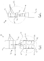
- Fig. 1 shows a bifurcated trunk section of a stent graft according to the invention;
- Fig. 2 illustrates a leg section of the stent graft according to the invention;
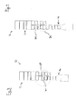
- Fig. 3 illustrates a bifurcated trunk section and leg section of the stent graft shown in Figs. 1 and 2, superimposed over one another at their respected maximum deployed diameters, and at a preferred maximum axial overlap between the sections; and
- Fig. 4 illustrates a bifurcated trunk section and leg section of the stent graft shown in Figs. 1 and 2, superimposed over one another at their respected maximum deployed diameters, and at a preferred minimum axial overlap between the sections.
- Referring to the drawings, Figs. 1 and 2 show two components of a
stent graft 10. Thetrunk section 12 has an approximatelycircular inlet 14 at one end, and two approximatelycircular outlets 16, 18, at an opposite end. Inlet and outlet are derived from the intended direction of blood flow, indicated byarrow 28, through thetrunk section 14 when positioned in the abdominal aorta and iliac arteries of a patient. Thetrunk section 12 bifurcates at point 15 betweeninlet 14 andoutlets 16, 18 into two flow channels, 20, 22, respectively. Preferably, thetrunk section 12 is comprised ofplural stent segments 24 along its length, secured to and joined by avascular graft 26 which surrounds thesegments 24 and defines the flow through thetrunk section 12. However, a unitary stent structure may be used as well, in addition to more orfewer segments 24 of varying length than shown in this exemplary embodiment. In a preferred embodiment, stent segments are approximately 1 cm in axial length. - Referring now to the bifurcated section highlighted by
circle 30, according to the exemplary embodiment, theflow channels 20, 22 are each tapered, and reduce in diameter along their length between point 15 andoutlets 16, 18. - Turning now to Fig. 2,
stent graft 10 includes a leg section, generally 40.Leg section 40 has a generallycircular inlet 42.Graft section 44 defines a flow path betweeninlet 42 and a generallycircular outlet 46. Inlet and outlet are derived from the intended direction of blood flow, indicated byarrow 48, through theleg section 40 when positioned in the abdominal aorta and iliac arteries of a patient. Preferably, theleg section 40 is comprised of plural stent segments 50 along its length, secured to and joined byvascular graft 44 which surrounds the segments 50 and defines the flow through theleg section 40. However, a unitary stent structure may be used as well, in addition to more or fewer segments 50 of varying length than shown in this exemplary embodiment. - Referring now to the inlet section highlighted by circle 52, according to the exemplary embodiment, the
leg section 40 is tapered, and reduces in diameter along its length at least betweeninlet 42 and some arbitrary point along its length. As shown in the exemplary embodiment, theleg portion 40 also expands in diameter from a minimum diameter along its length to a larger diameter at the generallycircular outlet 46. However, this is merely optional. This expanded deployed diameter may be constrained by the vessel in which theoutlet 46 of theleg portion 40 is deployed. Alternately, the taper may cease along its length, at which point the diameter may be arbitrarily set to suit the needs of the particular application, including continuing at a uniform diameter to theoutlet 46. Alternatively, the minimum diameter may itself occur atoutlet 46. - Moreover, the
taper angle graft 10, by reducing flow turbulence. Reduced turbulence reduces the fluid pressures in thegraft 10, thereby reducing stress on thegraft 10, and particularlystent segments 24, 50 thereof. Accordingly thegraft 10 is more resilient and enjoys longer service life. - Preferably, the
stent segments 24, 50 forming the structure ofstent graft 10 comprise a shape-memory material, more preferably Nitinol. Having been shape-set to a deployed diameter, the stent graft may be crimped to a smaller delivery diameter for percutaneous delivery by minimally invasive surgical techniques. - In use, the
trunk section 12 ofstent graft 10 would first be deployed in the abdominal aorta of the patient. Exposed to the heat of the patient's body temperature, and/or released from the constraint of a delivery apparatus, thestent graft 10 would expand to its deployed size, and fix against the walls of the aorta. Subsequently, one or twoleg sections 40 would be deployed inside either or both offlow channels 20, 22. Preferably, theinlet 42 ofleg section 40 would be deployed as close as practicable to the bifurcation point 15 of thetrunk section 12. This affords the maximum overlap between thetrunk section 12 and theleg section 40, which increases the pull-out force necessary to dislodge the leg section. Accordingly, theleg section 40 is more resistant to dislodgment. However, in practice, in situ sizing of the length of thestent graft 10 is often necessary, and the length of overlap betweentrunk section 12 andleg section 40 can be reduced as necessary, as shown in Figs. 3 and 4. - The deployed diameter of the
inlet 42 ofleg section 40 is at least as large or larger than the deployed diameter offlow channels 20, 22 at their largest dimensions adjacent the bifurcation point 15 oftrunk section 12. Additionally, thetaper angle 32 offlow channels 20, 22, is at least approximately equal to or greater than thetaper angle 54 of the tapered portion ofleg section 40. Preferably,taper angle 32 andtaper angle 54 are approximately equal. Therefore, presuming maximum overlap of theleg section 40 andflow channel 20, 22, the deployed diameter of theoutlets 16, 18, is as least the same size or smaller than the corresponding deployed diameter ofleg section 40 an equal distance frominlet 42 asoutlet 16, 18 is from bifurcation point 15. - Accordingly, when a
leg section 40 is inserted into aflow channel 20, 22, the deployed diameter of theleg section 40 would seek to exceed the inner deployed diameter of theflow channel 20, 22, but for containment of theleg section 40 by theflow channel 20, 22. The pull-out force necessary to dislodge the leg section from the flow channel increases with the amount by which the deployed diameter of theleg portion 40 exceeds the deployed diameter of theflow channel 20, 22, and also with the length of overlap between theleg section 40 and theflow channel 20, 22. Further, the pull-out force necessary to dislodge theleg section 40 increases with thetaper angle 32. - Referring now to Figs. 3 & 4,
stent graft 10 is illustrated withleg section 40 superimposed overflow channel 20, both in fully deployed diameters, at a preferred maximum (Fig. 3) and preferred minimum (Fig. 4) amounts of axial overlap length between the two. It will be appreciated that more or overlap may be used, within the dimensional constraints of theleg section 40 andflow channel 20. In Fig. 3, it will be seen that the diameter differential between theleg section 40 and theflow channel 20 at any given point along their lengths is reduced by increasing amount of overlap, in conjunction with the taper angles 32, 54, highlighted bycircle 60. Comparing now to Fig. 4, the axial overlap betweenleg section 40 andflow channel 20 is highlighted bycircle 70. Although the lengths of the overlap is reduced as compared to Fig. 3, the differential in deployed diameter betweenleg section 40 andflow channel 20 is increased, in part due to the taper angles 32, 54. Any decrease in pull out force in the configuration of Fig. 4 because of the reduced overlap length is compensated for by the increase in pull out force by the increased differential in deployed diameter. Therefore, a surgeon can size the overall length of thestent graft 10 in situ without compromising pull-out force of theleg section 40.
Claims (9)
- A prosthetic stent graft comprising:a trunk section having a bifurcated vascular graft having a first inlet and first and second flow channels in fluid communication with first and second outlets, the vascular graft supported by first one or more stent sections;each of the first and second flow channels having a first taper angle, whereby the respective flow channel decreases in cross-sectional area along its length between a bifurcation point in the trunk section to an outlet of the flow channel;a leg section having a tubular vascular graft having a second inlet with a deployed diameter at least as large or larger than a deployed diameter of the first or second outlet of the first or second flow channel, respectively, and a third flow channel in fluid communication with a third outlet, the vascular graft supported by second one or more stent sections; andthe leg section having a second taper angle, whereby the third flow channel decreases in cross-sectional area along its length between the second inlet and a location along the length of the leg section.
- The prosthetic stent graft according to claim 1, in which the first one or more stent sections or the second one or more stent sections comprise a shape memory material.
- The prosthetic stent graft according to claim 2, in which the shape memory material comprises Nitinol.
- The prosthetic stent graft according to claim 1, in which the first taper angle is greater than or equal to the second taper angle.
- The prosthetic stent graft according to claim 1, in which the first taper angle is approximately equal to the second taper angle.
- The prosthetic stent graft according to claim 1, in which the deployed diameter of the second inlet of the leg section is at least as large or larger than the deployed diameter of the first or second flow channel adjacent the bifurcation point of trunk section.
- The prosthetic stent graft according to claim 1, in which a deployed diameter of first or second outlet is as least the same as or smaller than the deployed diameter of the leg section at an equal distance from the second inlet as the first or second outlet is from bifurcation point.
- The prosthetic stent graft according to claim 1, in which the bifurcated vascular graft of the trunk section surrounds and is secured to the first one or more stent segments.
- The prosthetic stent graft according to claim 1, in which the tubular vascular graft of the leg section surrounds and is secured to the second one or more stent segments.
Applications Claiming Priority (1)
| Application Number | Priority Date | Filing Date | Title |
|---|---|---|---|
| US11/324,682 US20070156228A1 (en) | 2006-01-03 | 2006-01-03 | Prosthetic stent graft for treatment of abdominal aortic aneurysm |
Publications (2)
| Publication Number | Publication Date |
|---|---|
| EP1803419A1 true EP1803419A1 (en) | 2007-07-04 |
| EP1803419B1 EP1803419B1 (en) | 2014-03-05 |
Family
ID=37836594
Family Applications (1)
| Application Number | Title | Priority Date | Filing Date |
|---|---|---|---|
| EP07250009.3A Active EP1803419B1 (en) | 2006-01-03 | 2007-01-03 | Prosthetic stent graft for treatment of aortic aneurysm |
Country Status (4)
| Country | Link |
|---|---|
| US (1) | US20070156228A1 (en) |
| EP (1) | EP1803419B1 (en) |
| JP (1) | JP5111859B2 (en) |
| CA (1) | CA2572720C (en) |
Families Citing this family (33)
| Publication number | Priority date | Publication date | Assignee | Title |
|---|---|---|---|---|
| US5347780A (en) | 1989-10-12 | 1994-09-20 | Georgia-Pacific Corporation | Gypsum fiberboard door frame |
| JP2908770B2 (en) | 1997-03-06 | 1999-06-21 | 鹿島建設株式会社 | Glass mounting structure |
| US7147661B2 (en) | 2001-12-20 | 2006-12-12 | Boston Scientific Santa Rosa Corp. | Radially expandable stent |
| US8425549B2 (en) | 2002-07-23 | 2013-04-23 | Reverse Medical Corporation | Systems and methods for removing obstructive matter from body lumens and treating vascular defects |
| US7763063B2 (en) | 2003-09-03 | 2010-07-27 | Bolton Medical, Inc. | Self-aligning stent graft delivery system, kit, and method |
| US8292943B2 (en) | 2003-09-03 | 2012-10-23 | Bolton Medical, Inc. | Stent graft with longitudinal support member |
| US9198786B2 (en) | 2003-09-03 | 2015-12-01 | Bolton Medical, Inc. | Lumen repair device with capture structure |
| US11259945B2 (en) | 2003-09-03 | 2022-03-01 | Bolton Medical, Inc. | Dual capture device for stent graft delivery system and method for capturing a stent graft |
| US11596537B2 (en) | 2003-09-03 | 2023-03-07 | Bolton Medical, Inc. | Delivery system and method for self-centering a proximal end of a stent graft |
| US20080264102A1 (en) | 2004-02-23 | 2008-10-30 | Bolton Medical, Inc. | Sheath Capture Device for Stent Graft Delivery System and Method for Operating Same |
| US20070198078A1 (en) | 2003-09-03 | 2007-08-23 | Bolton Medical, Inc. | Delivery system and method for self-centering a Proximal end of a stent graft |
| US8500792B2 (en) | 2003-09-03 | 2013-08-06 | Bolton Medical, Inc. | Dual capture device for stent graft delivery system and method for capturing a stent graft |
| US9198687B2 (en) | 2007-10-17 | 2015-12-01 | Covidien Lp | Acute stroke revascularization/recanalization systems processes and products thereby |
| US11337714B2 (en) | 2007-10-17 | 2022-05-24 | Covidien Lp | Restoring blood flow and clot removal during acute ischemic stroke |
| US8926680B2 (en) | 2007-11-12 | 2015-01-06 | Covidien Lp | Aneurysm neck bridging processes with revascularization systems methods and products thereby |
| US8066757B2 (en) | 2007-10-17 | 2011-11-29 | Mindframe, Inc. | Blood flow restoration and thrombus management methods |
| US10123803B2 (en) | 2007-10-17 | 2018-11-13 | Covidien Lp | Methods of managing neurovascular obstructions |
| US8585713B2 (en) | 2007-10-17 | 2013-11-19 | Covidien Lp | Expandable tip assembly for thrombus management |
| US9220522B2 (en) | 2007-10-17 | 2015-12-29 | Covidien Lp | Embolus removal systems with baskets |
| US8088140B2 (en) | 2008-05-19 | 2012-01-03 | Mindframe, Inc. | Blood flow restorative and embolus removal methods |
| CN103549986B (en) | 2008-02-22 | 2015-12-09 | 泰科保健集团有限合伙公司 | The thrombosis device agglomerate of removable combination |
| EP2271390A4 (en) | 2008-04-11 | 2016-07-20 | Covidien Lp | Monorail neuro-microcatheter for delivery of medical devices to treat stroke, processes and products thereby |
| CN102076281B (en) | 2008-06-30 | 2014-11-05 | 波顿医疗公司 | Systems and methods for abdominal aortic aneurysm |
| EP2349080B1 (en) | 2008-10-22 | 2016-04-13 | Boston Scientific Scimed, Inc. | Shape memory tubular stent with grooves |
| CN106551740B (en) | 2009-03-13 | 2020-03-27 | 波顿医疗公司 | System and method for deploying an endoluminal prosthesis at a surgical site |
| US8758423B2 (en) * | 2009-06-18 | 2014-06-24 | Graftcraft I Goteborg Ab | Device and method for treating ruptured aneurysms |
| ES2658237T3 (en) | 2012-02-27 | 2018-03-08 | Hiroshima University | Stent graft |
| EP3141223A1 (en) | 2012-04-12 | 2017-03-15 | Bolton Medical, Inc. | Vascular prosthetic delivery device |
| US9132025B2 (en) | 2012-06-15 | 2015-09-15 | Trivascular, Inc. | Bifurcated endovascular prosthesis having tethered contralateral leg |
| US9439751B2 (en) | 2013-03-15 | 2016-09-13 | Bolton Medical, Inc. | Hemostasis valve and delivery systems |
| DE102018111614A1 (en) * | 2018-05-15 | 2019-11-21 | Jörg Teßarek | Multi-lumen implant |
| PL3941392T3 (en) | 2019-03-20 | 2025-08-25 | inQB8 Medical Technologies, LLC | Aortic dissection implant |
| WO2021262264A1 (en) | 2020-06-24 | 2021-12-30 | Bolton Medical, Inc. | Anti-backspin component for vascular prosthesis delivery device |
Citations (2)
| Publication number | Priority date | Publication date | Assignee | Title |
|---|---|---|---|---|
| WO1997012562A1 (en) * | 1995-10-03 | 1997-04-10 | Medtronic, Inc. | Modular intraluminal prostheses construction and methods |
| EP1029518A2 (en) * | 1999-02-16 | 2000-08-23 | Hector Daniel Barone | Aortic graft for treating abdominal aortic aneurysms and use of the graft |
Family Cites Families (13)
| Publication number | Priority date | Publication date | Assignee | Title |
|---|---|---|---|---|
| US6051020A (en) * | 1994-02-09 | 2000-04-18 | Boston Scientific Technology, Inc. | Bifurcated endoluminal prosthesis |
| US5609627A (en) * | 1994-02-09 | 1997-03-11 | Boston Scientific Technology, Inc. | Method for delivering a bifurcated endoluminal prosthesis |
| US6099558A (en) * | 1995-10-10 | 2000-08-08 | Edwards Lifesciences Corp. | Intraluminal grafting of a bifuricated artery |
| US6576009B2 (en) * | 1995-12-01 | 2003-06-10 | Medtronic Ave, Inc. | Bifurcated intraluminal prostheses construction and methods |
| US5902475A (en) * | 1997-04-08 | 1999-05-11 | Interventional Technologies, Inc. | Method for manufacturing a stent |
| US6129756A (en) * | 1998-03-16 | 2000-10-10 | Teramed, Inc. | Biluminal endovascular graft system |
| US6273909B1 (en) * | 1998-10-05 | 2001-08-14 | Teramed Inc. | Endovascular graft system |
| US6569193B1 (en) * | 1999-07-22 | 2003-05-27 | Advanced Cardiovascular Systems, Inc. | Tapered self-expanding stent |
| US6280466B1 (en) * | 1999-12-03 | 2001-08-28 | Teramed Inc. | Endovascular graft system |
| US7666221B2 (en) * | 2000-05-01 | 2010-02-23 | Endovascular Technologies, Inc. | Lock modular graft component junctions |
| AU2002360765C1 (en) * | 2001-12-20 | 2009-06-11 | Trivascular, Inc. | Advanced endovascular graft |
| US7235095B2 (en) * | 2002-02-22 | 2007-06-26 | Scimed Life Systems, Inc. | Method and system for deploying multi-part endoluminal devices |
| US7294147B2 (en) * | 2002-08-23 | 2007-11-13 | Cook Incorporated | Composite prosthesis |
-
2006
- 2006-01-03 US US11/324,682 patent/US20070156228A1/en not_active Abandoned
-
2007
- 2007-01-02 CA CA2572720A patent/CA2572720C/en active Active
- 2007-01-03 EP EP07250009.3A patent/EP1803419B1/en active Active
- 2007-01-04 JP JP2007000222A patent/JP5111859B2/en not_active Expired - Fee Related
Patent Citations (2)
| Publication number | Priority date | Publication date | Assignee | Title |
|---|---|---|---|---|
| WO1997012562A1 (en) * | 1995-10-03 | 1997-04-10 | Medtronic, Inc. | Modular intraluminal prostheses construction and methods |
| EP1029518A2 (en) * | 1999-02-16 | 2000-08-23 | Hector Daniel Barone | Aortic graft for treating abdominal aortic aneurysms and use of the graft |
Also Published As
| Publication number | Publication date |
|---|---|
| US20070156228A1 (en) | 2007-07-05 |
| CA2572720A1 (en) | 2007-07-03 |
| JP2007181701A (en) | 2007-07-19 |
| EP1803419B1 (en) | 2014-03-05 |
| CA2572720C (en) | 2016-10-25 |
| JP5111859B2 (en) | 2013-01-09 |
Similar Documents
| Publication | Publication Date | Title |
|---|---|---|
| EP1803419B1 (en) | Prosthetic stent graft for treatment of aortic aneurysm | |
| US7674284B2 (en) | Endoluminal graft | |
| US6652580B1 (en) | Modular, staged graft and attachment system for endovascular repair | |
| CN102415909B (en) | False chamber stopper | |
| US9101456B2 (en) | Thoracic aorta stent graft with access region | |
| US8021419B2 (en) | Stent graft | |
| EP2387374B1 (en) | Paraplegia prevention stent graft | |
| US9737394B2 (en) | Stent-graft prosthesis for placement in the abdominal aorta | |
| US11813185B2 (en) | Self-orienting endovascular delivery system | |
| US9211183B2 (en) | Thoracic stent graft with guide arrangement | |
| US12201510B2 (en) | Self-curving stent-graft | |
| US20110224774A1 (en) | Endoprosthesis and delivery system for delivering the endoprosthesis within a vessel of a patient | |
| EP2907478A1 (en) | Locking mechanism for securing the interface between stent grafts | |
| JP2015517845A (en) | Stent graft prosthesis for placement in the abdominal aorta | |
| EP1803418B1 (en) | D-shape stent for treatment of abdominal aortic aneurysm | |
| JP2007514498A (en) | Interconnected leg extensions for endoluminal prostheses | |
| EP2815722B1 (en) | Endovascular graft with an expanded lumen at a bifurcation | |
| CN104023672B (en) | Method and apparatus for the endovascular treatment of aortic disease | |
| WO2011116307A1 (en) | Thoracic stent graft | |
| US20190008631A1 (en) | Systems and methods with fenestrated graft and filling structure | |
| EP3150167A1 (en) | Modular system with at least one branch graft | |
| EP1825822B1 (en) | A sealing gasket for a prosthetic vascular stent |
Legal Events
| Date | Code | Title | Description |
|---|---|---|---|
| PUAI | Public reference made under article 153(3) epc to a published international application that has entered the european phase |
Free format text: ORIGINAL CODE: 0009012 |
|
| AK | Designated contracting states |
Kind code of ref document: A1 Designated state(s): AT BE BG CH CY CZ DE DK EE ES FI FR GB GR HU IE IS IT LI LT LU LV MC NL PL PT RO SE SI SK TR |
|
| AX | Request for extension of the european patent |
Extension state: AL BA HR MK YU |
|
| 17P | Request for examination filed |
Effective date: 20071207 |
|
| 17Q | First examination report despatched |
Effective date: 20080116 |
|
| AKX | Designation fees paid |
Designated state(s): AT BE BG CH CY CZ DE DK EE ES FI FR GB GR HU IE IS IT LI LT LU LV MC NL PL PT RO SE SI SK TR |
|
| REG | Reference to a national code |
Ref country code: DE Ref legal event code: R079 Ref document number: 602007035329 Country of ref document: DE Free format text: PREVIOUS MAIN CLASS: A61F0002060000 Ipc: A61F0002070000 |
|
| RIC1 | Information provided on ipc code assigned before grant |
Ipc: A61F 2/07 20130101AFI20130808BHEP |
|
| GRAP | Despatch of communication of intention to grant a patent |
Free format text: ORIGINAL CODE: EPIDOSNIGR1 |
|
| INTG | Intention to grant announced |
Effective date: 20130930 |
|
| GRAS | Grant fee paid |
Free format text: ORIGINAL CODE: EPIDOSNIGR3 |
|
| GRAA | (expected) grant |
Free format text: ORIGINAL CODE: 0009210 |
|
| AK | Designated contracting states |
Kind code of ref document: B1 Designated state(s): AT BE BG CH CY CZ DE DK EE ES FI FR GB GR HU IE IS IT LI LT LU LV MC NL PL PT RO SE SI SK TR |
|
| REG | Reference to a national code |
Ref country code: GB Ref legal event code: FG4D |
|
| REG | Reference to a national code |
Ref country code: CH Ref legal event code: NV Representative=s name: E. BLUM AND CO. AG PATENT- UND MARKENANWAELTE , CH Ref country code: CH Ref legal event code: EP |
|
| REG | Reference to a national code |
Ref country code: AT Ref legal event code: REF Ref document number: 654324 Country of ref document: AT Kind code of ref document: T Effective date: 20140315 |
|
| REG | Reference to a national code |
Ref country code: IE Ref legal event code: FG4D |
|
| REG | Reference to a national code |
Ref country code: DE Ref legal event code: R096 Ref document number: 602007035329 Country of ref document: DE Effective date: 20140410 |
|
| REG | Reference to a national code |
Ref country code: NL Ref legal event code: T3 |
|
| REG | Reference to a national code |
Ref country code: AT Ref legal event code: MK05 Ref document number: 654324 Country of ref document: AT Kind code of ref document: T Effective date: 20140305 |
|
| PG25 | Lapsed in a contracting state [announced via postgrant information from national office to epo] |
Ref country code: LT Free format text: LAPSE BECAUSE OF FAILURE TO SUBMIT A TRANSLATION OF THE DESCRIPTION OR TO PAY THE FEE WITHIN THE PRESCRIBED TIME-LIMIT Effective date: 20140305 |
|
| REG | Reference to a national code |
Ref country code: LT Ref legal event code: MG4D |
|
| PG25 | Lapsed in a contracting state [announced via postgrant information from national office to epo] |
Ref country code: AT Free format text: LAPSE BECAUSE OF FAILURE TO SUBMIT A TRANSLATION OF THE DESCRIPTION OR TO PAY THE FEE WITHIN THE PRESCRIBED TIME-LIMIT Effective date: 20140305 Ref country code: FI Free format text: LAPSE BECAUSE OF FAILURE TO SUBMIT A TRANSLATION OF THE DESCRIPTION OR TO PAY THE FEE WITHIN THE PRESCRIBED TIME-LIMIT Effective date: 20140305 Ref country code: SE Free format text: LAPSE BECAUSE OF FAILURE TO SUBMIT A TRANSLATION OF THE DESCRIPTION OR TO PAY THE FEE WITHIN THE PRESCRIBED TIME-LIMIT Effective date: 20140305 Ref country code: CY Free format text: LAPSE BECAUSE OF FAILURE TO SUBMIT A TRANSLATION OF THE DESCRIPTION OR TO PAY THE FEE WITHIN THE PRESCRIBED TIME-LIMIT Effective date: 20140305 |
|
| PG25 | Lapsed in a contracting state [announced via postgrant information from national office to epo] |
Ref country code: LV Free format text: LAPSE BECAUSE OF FAILURE TO SUBMIT A TRANSLATION OF THE DESCRIPTION OR TO PAY THE FEE WITHIN THE PRESCRIBED TIME-LIMIT Effective date: 20140305 |
|
| PG25 | Lapsed in a contracting state [announced via postgrant information from national office to epo] |
Ref country code: RO Free format text: LAPSE BECAUSE OF FAILURE TO SUBMIT A TRANSLATION OF THE DESCRIPTION OR TO PAY THE FEE WITHIN THE PRESCRIBED TIME-LIMIT Effective date: 20140305 Ref country code: BG Free format text: LAPSE BECAUSE OF FAILURE TO SUBMIT A TRANSLATION OF THE DESCRIPTION OR TO PAY THE FEE WITHIN THE PRESCRIBED TIME-LIMIT Effective date: 20140605 Ref country code: CZ Free format text: LAPSE BECAUSE OF FAILURE TO SUBMIT A TRANSLATION OF THE DESCRIPTION OR TO PAY THE FEE WITHIN THE PRESCRIBED TIME-LIMIT Effective date: 20140305 Ref country code: EE Free format text: LAPSE BECAUSE OF FAILURE TO SUBMIT A TRANSLATION OF THE DESCRIPTION OR TO PAY THE FEE WITHIN THE PRESCRIBED TIME-LIMIT Effective date: 20140305 Ref country code: IS Free format text: LAPSE BECAUSE OF FAILURE TO SUBMIT A TRANSLATION OF THE DESCRIPTION OR TO PAY THE FEE WITHIN THE PRESCRIBED TIME-LIMIT Effective date: 20140705 |
|
| PG25 | Lapsed in a contracting state [announced via postgrant information from national office to epo] |
Ref country code: ES Free format text: LAPSE BECAUSE OF FAILURE TO SUBMIT A TRANSLATION OF THE DESCRIPTION OR TO PAY THE FEE WITHIN THE PRESCRIBED TIME-LIMIT Effective date: 20140305 Ref country code: PL Free format text: LAPSE BECAUSE OF FAILURE TO SUBMIT A TRANSLATION OF THE DESCRIPTION OR TO PAY THE FEE WITHIN THE PRESCRIBED TIME-LIMIT Effective date: 20140305 Ref country code: SK Free format text: LAPSE BECAUSE OF FAILURE TO SUBMIT A TRANSLATION OF THE DESCRIPTION OR TO PAY THE FEE WITHIN THE PRESCRIBED TIME-LIMIT Effective date: 20140305 |
|
| REG | Reference to a national code |
Ref country code: DE Ref legal event code: R097 Ref document number: 602007035329 Country of ref document: DE |
|
| PG25 | Lapsed in a contracting state [announced via postgrant information from national office to epo] |
Ref country code: PT Free format text: LAPSE BECAUSE OF FAILURE TO SUBMIT A TRANSLATION OF THE DESCRIPTION OR TO PAY THE FEE WITHIN THE PRESCRIBED TIME-LIMIT Effective date: 20140707 |
|
| PLBE | No opposition filed within time limit |
Free format text: ORIGINAL CODE: 0009261 |
|
| STAA | Information on the status of an ep patent application or granted ep patent |
Free format text: STATUS: NO OPPOSITION FILED WITHIN TIME LIMIT |
|
| PG25 | Lapsed in a contracting state [announced via postgrant information from national office to epo] |
Ref country code: DK Free format text: LAPSE BECAUSE OF FAILURE TO SUBMIT A TRANSLATION OF THE DESCRIPTION OR TO PAY THE FEE WITHIN THE PRESCRIBED TIME-LIMIT Effective date: 20140305 |
|
| 26N | No opposition filed |
Effective date: 20141208 |
|
| REG | Reference to a national code |
Ref country code: DE Ref legal event code: R097 Ref document number: 602007035329 Country of ref document: DE Effective date: 20141208 |
|
| PG25 | Lapsed in a contracting state [announced via postgrant information from national office to epo] |
Ref country code: SI Free format text: LAPSE BECAUSE OF FAILURE TO SUBMIT A TRANSLATION OF THE DESCRIPTION OR TO PAY THE FEE WITHIN THE PRESCRIBED TIME-LIMIT Effective date: 20140305 |
|
| PG25 | Lapsed in a contracting state [announced via postgrant information from national office to epo] |
Ref country code: LU Free format text: LAPSE BECAUSE OF FAILURE TO SUBMIT A TRANSLATION OF THE DESCRIPTION OR TO PAY THE FEE WITHIN THE PRESCRIBED TIME-LIMIT Effective date: 20150103 |
|
| PG25 | Lapsed in a contracting state [announced via postgrant information from national office to epo] |
Ref country code: MC Free format text: LAPSE BECAUSE OF FAILURE TO SUBMIT A TRANSLATION OF THE DESCRIPTION OR TO PAY THE FEE WITHIN THE PRESCRIBED TIME-LIMIT Effective date: 20140305 |
|
| REG | Reference to a national code |
Ref country code: FR Ref legal event code: PLFP Year of fee payment: 10 |
|
| PG25 | Lapsed in a contracting state [announced via postgrant information from national office to epo] |
Ref country code: GR Free format text: LAPSE BECAUSE OF FAILURE TO SUBMIT A TRANSLATION OF THE DESCRIPTION OR TO PAY THE FEE WITHIN THE PRESCRIBED TIME-LIMIT Effective date: 20140606 |
|
| REG | Reference to a national code |
Ref country code: FR Ref legal event code: PLFP Year of fee payment: 11 |
|
| PG25 | Lapsed in a contracting state [announced via postgrant information from national office to epo] |
Ref country code: HU Free format text: LAPSE BECAUSE OF FAILURE TO SUBMIT A TRANSLATION OF THE DESCRIPTION OR TO PAY THE FEE WITHIN THE PRESCRIBED TIME-LIMIT; INVALID AB INITIO Effective date: 20070103 |
|
| PG25 | Lapsed in a contracting state [announced via postgrant information from national office to epo] |
Ref country code: TR Free format text: LAPSE BECAUSE OF FAILURE TO SUBMIT A TRANSLATION OF THE DESCRIPTION OR TO PAY THE FEE WITHIN THE PRESCRIBED TIME-LIMIT Effective date: 20140305 |
|
| REG | Reference to a national code |
Ref country code: FR Ref legal event code: PLFP Year of fee payment: 12 |
|
| REG | Reference to a national code |
Ref country code: GB Ref legal event code: 732E Free format text: REGISTERED BETWEEN 20180614 AND 20180620 |
|
| REG | Reference to a national code |
Ref country code: CH Ref legal event code: NV Representative=s name: SERVOPATENT GMBH, CH Ref country code: CH Ref legal event code: PUE Owner name: CARDINAL HEALTH SWITZERLAND 515 GMBH, CH Free format text: FORMER OWNER: CORDIS CORPORATION, US |
|
| REG | Reference to a national code |
Ref country code: CH Ref legal event code: PCAR Free format text: NEW ADDRESS: WANNERSTRASSE 9/1, 8045 ZUERICH (CH) |
|
| REG | Reference to a national code |
Ref country code: DE Ref legal event code: R082 Ref document number: 602007035329 Country of ref document: DE Representative=s name: PROCK, THOMAS, DR., GB |
|
| REG | Reference to a national code |
Ref country code: NL Ref legal event code: PD Owner name: CARDINAL HEALTH SWITZERLAND 515 GMBH; CH Free format text: DETAILS ASSIGNMENT: CHANGE OF OWNER(S), ASSIGNMENT; FORMER OWNER NAME: CORDIS CORPORATION Effective date: 20200708 |
|
| REG | Reference to a national code |
Ref country code: GB Ref legal event code: 732E Free format text: REGISTERED BETWEEN 20201126 AND 20201202 |
|
| REG | Reference to a national code |
Ref country code: DE Ref legal event code: R082 Ref document number: 602007035329 Country of ref document: DE Representative=s name: PROCK, THOMAS, DR., GB Ref country code: DE Ref legal event code: R081 Ref document number: 602007035329 Country of ref document: DE Owner name: CARDINAL HEALTH SWITZERLAND 515 GMBH, CH Free format text: FORMER OWNER: CORDIS CORP., MIAMI LAKES, FLA., US |
|
| PGFP | Annual fee paid to national office [announced via postgrant information from national office to epo] |
Ref country code: IE Payment date: 20230127 Year of fee payment: 17 Ref country code: FR Payment date: 20230125 Year of fee payment: 17 Ref country code: CH Payment date: 20230130 Year of fee payment: 17 |
|
| PGFP | Annual fee paid to national office [announced via postgrant information from national office to epo] |
Ref country code: IT Payment date: 20230120 Year of fee payment: 17 Ref country code: GB Payment date: 20230127 Year of fee payment: 17 Ref country code: DE Payment date: 20230127 Year of fee payment: 17 Ref country code: BE Payment date: 20230127 Year of fee payment: 17 |
|
| PGFP | Annual fee paid to national office [announced via postgrant information from national office to epo] |
Ref country code: NL Payment date: 20230126 Year of fee payment: 17 |
|
| REG | Reference to a national code |
Ref country code: DE Ref legal event code: R119 Ref document number: 602007035329 Country of ref document: DE |
|
| REG | Reference to a national code |
Ref country code: CH Ref legal event code: PL |
|
| REG | Reference to a national code |
Ref country code: NL Ref legal event code: MM Effective date: 20240201 |
|
| GBPC | Gb: european patent ceased through non-payment of renewal fee |
Effective date: 20240103 |
|
| PG25 | Lapsed in a contracting state [announced via postgrant information from national office to epo] |
Ref country code: DE Free format text: LAPSE BECAUSE OF NON-PAYMENT OF DUE FEES Effective date: 20240801 |
|
| PG25 | Lapsed in a contracting state [announced via postgrant information from national office to epo] |
Ref country code: GB Free format text: LAPSE BECAUSE OF NON-PAYMENT OF DUE FEES Effective date: 20240103 |
|
| PG25 | Lapsed in a contracting state [announced via postgrant information from national office to epo] |
Ref country code: BE Free format text: LAPSE BECAUSE OF NON-PAYMENT OF DUE FEES Effective date: 20240131 |
|
| PG25 | Lapsed in a contracting state [announced via postgrant information from national office to epo] |
Ref country code: FR Free format text: LAPSE BECAUSE OF NON-PAYMENT OF DUE FEES Effective date: 20240131 |
|
| PG25 | Lapsed in a contracting state [announced via postgrant information from national office to epo] |
Ref country code: NL Free format text: LAPSE BECAUSE OF NON-PAYMENT OF DUE FEES Effective date: 20240201 |
|
| PG25 | Lapsed in a contracting state [announced via postgrant information from national office to epo] |
Ref country code: CH Free format text: LAPSE BECAUSE OF NON-PAYMENT OF DUE FEES Effective date: 20240131 |
|
| PG25 | Lapsed in a contracting state [announced via postgrant information from national office to epo] |
Ref country code: NL Free format text: LAPSE BECAUSE OF NON-PAYMENT OF DUE FEES Effective date: 20240201 Ref country code: GB Free format text: LAPSE BECAUSE OF NON-PAYMENT OF DUE FEES Effective date: 20240103 Ref country code: FR Free format text: LAPSE BECAUSE OF NON-PAYMENT OF DUE FEES Effective date: 20240131 Ref country code: DE Free format text: LAPSE BECAUSE OF NON-PAYMENT OF DUE FEES Effective date: 20240801 Ref country code: CH Free format text: LAPSE BECAUSE OF NON-PAYMENT OF DUE FEES Effective date: 20240131 Ref country code: BE Free format text: LAPSE BECAUSE OF NON-PAYMENT OF DUE FEES Effective date: 20240131 |
|
| REG | Reference to a national code |
Ref country code: BE Ref legal event code: MM Effective date: 20240131 |
|
| PG25 | Lapsed in a contracting state [announced via postgrant information from national office to epo] |
Ref country code: IE Free format text: LAPSE BECAUSE OF NON-PAYMENT OF DUE FEES Effective date: 20240103 |
|
| PG25 | Lapsed in a contracting state [announced via postgrant information from national office to epo] |
Ref country code: IE Free format text: LAPSE BECAUSE OF NON-PAYMENT OF DUE FEES Effective date: 20240103 |
|
| PG25 | Lapsed in a contracting state [announced via postgrant information from national office to epo] |
Ref country code: IT Free format text: LAPSE BECAUSE OF NON-PAYMENT OF DUE FEES Effective date: 20240103 |