EP1802936B1 - Tape measure housing - Google Patents
Tape measure housing Download PDFInfo
- Publication number
- EP1802936B1 EP1802936B1 EP05789159.0A EP05789159A EP1802936B1 EP 1802936 B1 EP1802936 B1 EP 1802936B1 EP 05789159 A EP05789159 A EP 05789159A EP 1802936 B1 EP1802936 B1 EP 1802936B1
- Authority
- EP
- European Patent Office
- Prior art keywords
- housing
- tape measure
- gas
- elastomeric material
- cavities
- Prior art date
- Legal status (The legal status is an assumption and is not a legal conclusion. Google has not performed a legal analysis and makes no representation as to the accuracy of the status listed.)
- Expired - Lifetime
Links
Images

Classifications
-
- G—PHYSICS
- G01—MEASURING; TESTING
- G01B—MEASURING LENGTH, THICKNESS OR SIMILAR LINEAR DIMENSIONS; MEASURING ANGLES; MEASURING AREAS; MEASURING IRREGULARITIES OF SURFACES OR CONTOURS
- G01B3/00—Measuring instruments characterised by the use of mechanical techniques
- G01B3/10—Measuring tapes
- G01B3/1041—Measuring tapes characterised by casings
-
- G—PHYSICS
- G01—MEASURING; TESTING
- G01B—MEASURING LENGTH, THICKNESS OR SIMILAR LINEAR DIMENSIONS; MEASURING ANGLES; MEASURING AREAS; MEASURING IRREGULARITIES OF SURFACES OR CONTOURS
- G01B3/00—Measuring instruments characterised by the use of mechanical techniques
- G01B3/10—Measuring tapes
- G01B3/1041—Measuring tapes characterised by casings
- G01B3/1046—Details of external structure thereof, e.g. shapes for ensuring firmer hold
Definitions
- This invention relates to a housing for a tape measure and to a tape measure including such a housing.
- a spindle is usually formed on or connected to the housing that contains the wound tape measure spool and return spring.
- the housing is usually formed in two parts, one part bearing the spindle on which the spool is mounted, and the second part coordinating with the first part to either wholly or partially enclose the tape measure.
- the tape measure is wound on the spool. In either case, the complete housing having an opening through which the tape measure can be extended or retracted.
- a flexible long tape measure which is connected by a leader to a winding drum within a housing.
- the drum is usually formed integrally with or connected to a winding centre and winding handle used to wind the long tape measure onto the drum.
- the drum is usually at least partially enclosed by the housing.
- the housing is usually formed in at least two parts and has an opening through which the long tape measure can be extended and retracted.
- tape measure housings are typically made from moulded plastics material. This allows the casing to be relatively lightweight and easy to handle. The moulding operation also allows the incorporation of detailed functional shapes into the housing in a single forming step.
- tape measure housings made from moulded plastic materials due to their relative stiffness, they may be quite brittle and prone to breakage during impact.
- tape measures which have overjackets formed of resilient material. That is, a jacket is formed around the tape measure after the tape measure has been assembled, or the tape measure is inserted into a jacket after assembly of the tape measure.
- the jackets are typically provided for the purpose of improving the grip provided to a user. If made from resilient material, they have a further effect which is a limited shock-protection effect.
- GB2342086 discloses protective stuffed pads fixedly attached to the exterior surface of a tape measure housing with a binder or by recessed slot, T shaped slot or pit type slot, the inner cavity of the pads being filled with shock absorbing material enabling the pads to buffer the tape measure housing from forces liable to cause cracking or breakage.
- US6182916B discloses a measuring tape dispenser with an impact buffer housing and tentative tape halting device, in which the housing is at least or partially covered with an impact buffer layer formed of an elastic material so as to protect the housing from being deformed or even destroyed.
- WO04013570 discloses a tape measure which has a spooled measuring blade mounted via a rotatable connection within a casing.
- the tape measure has impact-protection components. These components may be resilient means arranged between the spooled blade and the case, such as at the rotatable connection. Further impact-protection components are resilient pads which are moulded into impact-vulnerable locations on the outer surface of the case.
- US4527334 discloses a measuring device comprising an outer casing and an inner drum mounted on a central hub of the casing.
- a resilient shock-absorbing bumper is provided around the periphery of the outer casing.
- US6226886 discloses a tape measure having a housing that encloses a coiled tape rule retractably mounted therein.
- the tape measure has a housing constructed with an outer coating of a soft, resilient and pliant material so to give an ergonomically efficient tape measure with a relatively soft, comfortable grip that will not easily slip out of a user's hands.
- gasfilled e.g. air-filled cavities in the resilient material provided on prior art housings, the protection advantages offered by the resilient material can be improved upon.
- the present invention provides, a tape measure housing having resilient elastomeric material located at its outer surface, wherein the resilient elastomeric material defines one or more gas-filled cavities, each of which is located on a line tangential to an outer wall of the housing between the outer wall of the housing and an outer wall of the resilient elastomeric material.
- the outer surface of the housing is the surface which is impacted upon when tape measure housing is dropped.
- the gas-filled cavities may be open to the atmosphere, and may have an opening on at least one outer surface of the resilient material, or an opening on at least two outer surfaces of the resilient material. Such cavities can be described as 'blind' and 'through' cavities respectively. Alternatively, the gasfilled cavities may not have an opening on at least one outer surface of the resilient material. Such cavities can be described as 'internal' cavities.
- the cavities described above run parallel to the surface of the housing which they are intended to protect, but may run in a different direction, particularly to provide a visual effect.
- the gas-filled cavities may be not open to the atmosphere.
- the gas in the cavities may be air or it may be another gas, or mixture of gases, such as nitrogen and carbon dioxide.
- the tape measure housing may be made from any suitable moulded plastics material, e.g. ABS, polycarbonate, polystyrene, polyester, nylon and acetal. Of these ABS is preferred.
- the resilient material may be an elastomeric material such as, for example, TPE, TPU, melt processable rubber and elastomeric alloy. Of these TPE and TPU are preferred.
- the resilient material may be used to hold a housing comprising two or more parts together, in addition to, or as a replacement for, conventional securing means.
- Housings wherein resilient material replaces conventional securing means are described in co-pending application GB 0416509.8, filed on 23 July 2004 .
- the resilient material may be attached to the housing in a number of ways. It may be moulded onto the housing, adhered to the housing, or if in the form of a jacket, slipped onto the housing after the housing is assembled. Of these, moulding-on and adhesion are the preferred options, with moulding-on being the most preferred option.
- the housing is for a short tape, then it usually has two substantially parallel faces which define between them a space for a spooled measuring tape, said space being circumscribed by an edge having a mouth through which the tape could be drawn.
- the resilient material which defines the cavities preferably covers the whole width of said edge and the cavities extend across at least 50%, preferably 60% or even 75%, of said width.
- the resilient material may extend along whole or part of the edge, and preferably extends along at least 50% of the length of the edge.
- the gas-filled cavities are preferably bounded on both sides, along the line tangential to an outer wall of the housing between the outer wall of the housing and an outer wall of the resilient material, with resilient material. This results in there being resilient material between the cavity and the outer wall of the housing.
- the gas-filled cavities are preferably of a predetermined volume, which volume is preferably sufficient to provide additional shock protection when compared against a measure where the cavity is not present.
- the gas-filled cavities tend to be elongate. It is preferred that the cross-section of the elongate gas-filled cavities is least 1mm 2 , 5mm 2 or even 10mm 2 . It is also preferred that the cross-section of the elongate gas-filled cavities is less than or equal to 75mm 2 , 50mm 2 or even 25mm 2 .
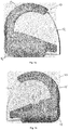
- Figs. 1a, 1b and 2 show a tape measure housing 10 for a short tape comprising two halves 12, 14 formed from injection moulded plastics material, e.g. ABS. Each half has moulded onto it elastomeric material pads 13, 15.
- the pads 13, 15 have two types of air-filled cavities.
- the first type are cavities 16, 18 provided in the corner distal from the mouth on the bottom edge of the housing through which a tape spooled in the housing is to be drawn. These cavities extend to the outside of the elastomeric pads, and hence are visible during the normal use of the housing.
- the cavities 16, 18 do extend to the join between the two halves 12, 14 of the housing 10, as can be seen in Fig 2 , but run parallel to the edge of the housing that joins the front and rear faces.
- cavities 17, 19 provided in both elastomeric pads are provided in the pads on the bottom edge of the casing and on the upper edges of the casing and, as above, run parallel to the edge of the housing that joins the front and rear faces. These cavities extend from the join between the two halves of the housing, but do not impinge on the outer surface of the pads, and therefore are not visible during normal use of the housing.
- the cavities 16, 17, 18, 19 have a cross-section of about 9mm 2 . These cavities protect the edge of the housing.
- the cavities 16, 17, 18, 19 can be formed during the moulding process.
- these types of cavities can be formed by automatic twin shot moulding or manual overmoulding.
- the plastics material e.g. ABS
- 14 being moulded is injected into a mould tool cavity, and this 'first shot' remains in the mould tool.
- a portion, which may be half, of the mould tool rotates or moves to expose a new moulding cavity, which is an extension of the first moulding cavity and is formed at least in part by the plastics material of the first shot.
- the newly formed moulding cavity is filled with the elastomeric material, e.g. TPE, as a 'second shot', and this elastomeric material forms an intimate, adhesive and/or mechanical bond with the plastics material from the first shot.
- the elastomeric material forms the pads 13, 15.
- the mould tool When the mould tool ejects the component after the second shot, the component is fully finished and consists of both the plastics and elastomeric materials.
- the first and second shot can happen consecutively or simultaneously during an automatic twin shot cycle because the moulding machine is fitted with two injection units, one for the plastics material, e.g. ABS and one for the elastomeric material, e.g. TPE.
- the gas-filled cavities 16, 17, 18, 19 are formed in the elastomeric material due to the shape of the second moulding cavity.
- the plastic materials for the case half 12, 14 being moulded is moulded in a conventional moulding machine and mould tool in the normal way.
- the plastics moulding which is formed is then manually inserted into a second mould tool.
- the second mould tool it is common for the second mould tool to be in another moulding machine and for the plastics material, e.g. ABS, mouldings to be transferred as they are moulded (no stock of plastics material parts).
- a stock of plastics material, e.g. ABS, parts is may be produced.
- the plastics material mould tool in the moulding machine is changed for the elastomeric material, e.g. TPE, tool and the stock of plastics material mouldings overmoulded with elastomeric material.
- the moulding cavities in the second mould tool are an extension of the moulding cavities in the first tool and are formed at least in part by the plastics material of the first shot.
- the elastomeric material, e.g. TPE, to form the pads 13, 15 is injected into the free moulding cavity space and forms an intimate, adhesive and/or mechanical bond with the plastics material.
- the gas filled cavities 16, 17, 18, 19 are formed in the elastomeric material due to the shape of the second moulding cavity.
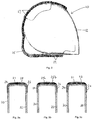
- Fig. 3 shows cross sections of a tape measure housing comprising two parts 20, 22. Each half of the housing has an overmoulded elastomeric pad 24, 26.
- Fig. 3a shows 'internal' cavities 27, 28 which are equivalent to the cavities 17, 19 around the edge of the housing in Figs. 1 and 2.
- Fig. 3c shows 'blind' cavities 21, 23 which are equivalent to the cavities 16, 18 on the corner of the housing in Figs. 1 and 2.
- Fig. 3b shows a 'through' cavity 25a, 25b which is combination of the 'internal' and 'blind' cavities of Figs. 3a and 3c .
- the cavities 25a, 25b extend from the join between the two parts of the housing 20, 22 to the outside of the elastomeric pads 24, 26, giving the visual impression of a single cavity which extends across the whole width of the edge of the housing.
- These 'through' cavities can be formed in the same manner as described above.
- Fig. 4 shows a cross section of a tape measure housing having two parts 20 and 22.
- the elastomeric material 32 comprises a cavity 34 which is sealed from the atmosphere and has an outer wall 35 and an inner wall 33. The cavity extends across the width of the edge of the housing.
- the elastomeric material engages with the halves of the housing 20 and 22 by means of lugs 36 which engage in complementary recesses 20a and 22a on the halves of the housing.
- the elastomeric material 32 can therefore provide an additional advantage of holding the two halves 20, 22 of the housing together, depending on its construction.
- the elastomeric material 32 will be manufactured separately from the housing 20, 22 and then slipped over it as part of the assembly process.
- a process called Gas Injection Moulding can be used to form the cavity 34 in the elastomeric material 32, as illustrated in Fig. 4 .
- the hot elastomeric material covers and seals the moulding cavity in the mould, but the quantity of elastomeric material is insufficient to fully fill the moulding cavity.
- a carefully metered quantity of gas for example, nitrogen or carbon dioxide
- the injection point is automatically sealed by the molten elastomeric material.
- the trapped injected gas forces the molten elastomeric material against the walls of the of the moulding cavity and forms the required gas filled cavity 34 in the elastomeric material.
- Gas injection equipment is well known in the moulding industry for the manufacture of hollow parts.
Landscapes
- Physics & Mathematics (AREA)
- General Physics & Mathematics (AREA)
- Casings For Electric Apparatus (AREA)
- Tape Measures (AREA)
- Injection Moulding Of Plastics Or The Like (AREA)
Description
- This invention relates to a housing for a tape measure and to a tape measure including such a housing.
- It is well known to provide a flexible short tape measure wound onto a spool such that the tape measure can be unwound from the spool for use and then retracted after use for convenient storage. A spindle is usually formed on or connected to the housing that contains the wound tape measure spool and return spring. The housing is usually formed in two parts, one part bearing the spindle on which the spool is mounted, and the second part coordinating with the first part to either wholly or partially enclose the tape measure. The tape measure is wound on the spool. In either case, the complete housing having an opening through which the tape measure can be extended or retracted.
- In addition, it is known to provide a flexible long tape measure which is connected by a leader to a winding drum within a housing. The drum is usually formed integrally with or connected to a winding centre and winding handle used to wind the long tape measure onto the drum. The drum is usually at least partially enclosed by the housing. The housing is usually formed in at least two parts and has an opening through which the long tape measure can be extended and retracted.
- For ease of manufacture, tape measure housings are typically made from moulded plastics material. This allows the casing to be relatively lightweight and easy to handle. The moulding operation also allows the incorporation of detailed functional shapes into the housing in a single forming step.
- A particular problem associated with tape measure housings made from moulded plastic materials is that due to their relative stiffness, they may be quite brittle and prone to breakage during impact.
- There are known tape measures which have overjackets formed of resilient material. That is, a jacket is formed around the tape measure after the tape measure has been assembled, or the tape measure is inserted into a jacket after assembly of the tape measure. The jackets are typically provided for the purpose of improving the grip provided to a user. If made from resilient material, they have a further effect which is a limited shock-protection effect.
- There are also known tape measures which have pads of resilient material which are attached to the tape measure housing, either by adhesive or by moulding in (for example as described in
WO 2004/013570 ). These resilient pads are often located at vulnerable locations on the outer surface of the housing, e.g. around the tape mouth (the opening in the housing from which the measuring blade is drawable) and the corners of the housing. -
GB2342086 -
US6182916B discloses a measuring tape dispenser with an impact buffer housing and tentative tape halting device, in which the housing is at least or partially covered with an impact buffer layer formed of an elastic material so as to protect the housing from being deformed or even destroyed. -
WO04013570 -
US4527334 discloses a measuring device comprising an outer casing and an inner drum mounted on a central hub of the casing. A resilient shock-absorbing bumper is provided around the periphery of the outer casing. -
US6226886 discloses a tape measure having a housing that encloses a coiled tape rule retractably mounted therein. The tape measure has a housing constructed with an outer coating of a soft, resilient and pliant material so to give an ergonomically efficient tape measure with a relatively soft, comfortable grip that will not easily slip out of a user's hands. - The present inventors have realised that by including gasfilled (e.g. air-filled) cavities in the resilient material provided on prior art housings, the protection advantages offered by the resilient material can be improved upon.
- Accordingly the present invention provides, a tape measure housing having resilient elastomeric material located at its outer surface, wherein the resilient elastomeric material defines one or more
gas-filled cavities, each of which is located on a line tangential to an outer wall of the housing between the outer wall of the housing and an outer wall of the resilient elastomeric material. - The outer surface of the housing is the surface which is impacted upon when tape measure housing is dropped.
- The gas-filled cavities may be open to the atmosphere, and may have an opening on at least one outer surface of the resilient material, or an opening on at least two outer surfaces of the resilient material. Such cavities can be described as 'blind' and 'through' cavities respectively. Alternatively, the gasfilled cavities may not have an opening on at least one outer surface of the resilient material. Such cavities can be described as 'internal' cavities.
- If the cavities are open to the atmosphere, then the gas filling them is air.
- Typically the cavities described above run parallel to the surface of the housing which they are intended to protect, but may run in a different direction, particularly to provide a visual effect.
- The gas-filled cavities may be not open to the atmosphere. In this case, the gas in the cavities may be air or it may be another gas, or mixture of gases, such as nitrogen and carbon dioxide.
- The tape measure housing may be made from any suitable moulded plastics material, e.g. ABS, polycarbonate, polystyrene, polyester, nylon and acetal. Of these ABS is preferred.
- The resilient material may be an elastomeric material such as, for example, TPE, TPU, melt processable rubber and elastomeric alloy. Of these TPE and TPU are preferred.
- The resilient material may be used to hold a housing comprising two or more parts together, in addition to, or as a replacement for, conventional securing means. Housings wherein resilient material replaces conventional securing means are described in co-pending application
GB 0416509.8, filed on 23 July 2004 - The resilient material may be attached to the housing in a number of ways. It may be moulded onto the housing, adhered to the housing, or if in the form of a jacket, slipped onto the housing after the housing is assembled. Of these, moulding-on and adhesion are the preferred options, with moulding-on being the most preferred option.
- If the housing is for a short tape, then it usually has two substantially parallel faces which define between them a space for a spooled measuring tape, said space being circumscribed by an edge having a mouth through which the tape could be drawn. In this case, the resilient material which defines the cavities preferably covers the whole width of said edge and the cavities extend across at least 50%, preferably 60% or even 75%, of said width. The resilient material may extend along whole or part of the edge, and preferably extends along at least 50% of the length of the edge.
- The gas-filled cavities are preferably bounded on both sides, along the line tangential to an outer wall of the housing between the outer wall of the housing and an outer wall of the resilient material, with resilient material. This results in there being resilient material between the cavity and the outer wall of the housing.
- The gas-filled cavities are preferably of a predetermined volume, which volume is preferably sufficient to provide additional shock protection when compared against a measure where the cavity is not present.
- The gas-filled cavities tend to be elongate. It is preferred that the cross-section of the elongate gas-filled cavities is least 1mm2, 5mm2 or even 10mm2. It is also preferred that the cross-section of the elongate gas-filled cavities is less than or equal to 75mm2, 50mm2 or even 25mm2.
- Preferred embodiments of the invention will now be described, by way of example only, with reference to the accompanying drawings, in which:
-
Fig. 1a is a front view of a tape measure housing of the invention; -
Fig. 1b is a rear view of the tape measure housing ofFig. 1a ; -
Fig. 2 is a front view of the tape measure housing ofFig. 1a , with the rubber moulding on the front half of the housing removed; -
Figs. 3a to 3c are cross-sectional views of parts of housings according to the present invention; -
Fig. 4 is a cross-sectional view of a further part of a housing according to the present invention. -
Figs. 1a, 1b and2 show atape measure housing 10 for a short tape comprising twohalves elastomeric material pads 13, 15. Thepads 13, 15 have two types of air-filled cavities. The first type arecavities cavities halves housing 10, as can be seen inFig 2 , but run parallel to the edge of the housing that joins the front and rear faces. - These
cavities - The other type of
cavities pad 15 inFig. 2 ) are provided in the pads on the bottom edge of the casing and on the upper edges of the casing and, as above, run parallel to the edge of the housing that joins the front and rear faces. These cavities extend from the join between the two halves of the housing, but do not impinge on the outer surface of the pads, and therefore are not visible during normal use of the housing. - The
cavities - The
cavities - In twin shot moulding the plastics material, e.g. ABS, for the
case half pads 13, 15. When the mould tool ejects the component after the second shot, the component is fully finished and consists of both the plastics and elastomeric materials. The first and second shot can happen consecutively or simultaneously during an automatic twin shot cycle because the moulding machine is fitted with two injection units, one for the plastics material, e.g. ABS and one for the elastomeric material, e.g. TPE. The gas-filledcavities - In manual overmoulding, sometimes termed 'mould-on', the plastic materials for the
case half - The moulding cavities in the second mould tool are an extension of the moulding cavities in the first tool and are formed at least in part by the plastics material of the first shot. The elastomeric material, e.g. TPE, to form the
pads 13, 15 is injected into the free moulding cavity space and forms an intimate, adhesive and/or mechanical bond with the plastics material. As in twin shot moulding, the gas filledcavities - The tooling for manual overmoulding is less complex and therefore cheaper than the tooling for twin shot moulding. However, manual overmoulding required two distinct moulding operations and is labour intensive and can lead to a greater variation in the quality of components.
- The types of cavities in
Figs. 1 and2 , and an additional type of cavity, are further illustrated inFig. 3 , which shows cross sections of a tape measure housing comprising twoparts elastomeric pad Fig. 3a shows 'internal'cavities cavities Figs. 1 and2. Fig. 3c shows 'blind'cavities cavities Figs. 1 and2. Fig. 3b shows a 'through'cavity 25a, 25b which is combination of the 'internal' and 'blind' cavities ofFigs. 3a and 3c . Thecavities 25a, 25b extend from the join between the two parts of thehousing elastomeric pads -
Fig. 4 shows a cross section of a tape measure housing having twoparts elastomeric material 32 comprises acavity 34 which is sealed from the atmosphere and has anouter wall 35 and aninner wall 33. The cavity extends across the width of the edge of the housing. The elastomeric material engages with the halves of thehousing lugs 36 which engage incomplementary recesses elastomeric material 32 can therefore provide an additional advantage of holding the twohalves elastomeric material 32 will be manufactured separately from thehousing - A process called Gas Injection Moulding can be used to form the
cavity 34 in theelastomeric material 32, as illustrated inFig. 4 . Before gas injection, the hot elastomeric material covers and seals the moulding cavity in the mould, but the quantity of elastomeric material is insufficient to fully fill the moulding cavity. During the elastomeric moulding process, a carefully metered quantity of gas (for example, nitrogen or carbon dioxide) is injected into the molten elastomeric material. As the flow of gas is turned off, the injection point is automatically sealed by the molten elastomeric material. - The trapped injected gas forces the molten elastomeric material against the walls of the of the moulding cavity and forms the required gas filled
cavity 34 in the elastomeric material. Gas injection equipment is well known in the moulding industry for the manufacture of hollow parts. - It is possible to provide an internal gas filled cavity in elastomeric material which is moulded onto the plastics case, as an alternative to the embodiment described above. This may be achieved by using gas injection moulding on a twin shot moulding tool. Such an embodiment may differ from that illustrated in
Figure 4 by the absence oflugs 36, although these lugs may be used to increase the durability of the moulded onelastomeric material 32.
Claims (13)
- A tape measure housing (10) having resilient material located at its outer surface, characterized in that said resilient material is a resilient elastomeric material, wherein the resilient elastomeric material defines one or more gas-filled cavities (16, 17, 18, 19, 27, 28, 21, 23, 25a, 25b, 34), each of which is located on a line tangential to an outer wall of the housing (10) between the outer wall of the housing (10) and an outer wall of the resilient elastomeric material.
- A tape measure housing (10) according to claim 1, wherein one or more of the gas-filled cavities (16, 17, 18, 19, 27, 28, 21, 23, 25a, 25b, 34) is open to the atmosphere.
- A tape measure housing (10) according to claim 2, wherein one or more of the gas-filled cavities (16, 17, 18, 19, 27, 28, 21, 23, 25a, 25b, 34) have an opening on at least one outer surface of the resilient elastomeric material.
- A tape measure housing (10) according to claim 3, wherein the one or more gas-filled cavities (16, 17, 18, 19, 27, 28, 21, 23, 25a, 25b, 34) have an opening on at least two outer surfaces of the resilient elastomeric material.
- A tape measure housing (10) according to claim 2, wherein one or more of the gas-filled cavities (16, 17, 18, 19, 27, 28, 21, 23, 25a, 25b, 34) do not have an opening on at least one outer surface of the resilient elastomeric material.
- A tape measure housing (10) according to anyone of claims 1 to 5, wherein at least one of the gas-filled cavities (16, 17, 18, 19, 27, 28, 21, 23, 25a, 25b, 34) are not open to the atmosphere.
- A tape measure according to claim 6, wherein the gas in said at least one of the gas-filled cavities (16, 17, 18, 19, 27, 28, 21, 23, 25a, 25b, 34) is air.
- A tape measure according to claim 6, wherein the gas in said at least one of the gas-filled cavities (16, 17, 18, 19, 27, 28, 21, 23, 25a, 25b, 34) is not air.
- A tape measure housing (10) according to anyone of claims 1 to 8, wherein at least some of the resilient elastomeric material is moulded onto the housing (10).
- A tape measure housing (10) according to anyone of claims 1 to 8, wherein at least some of the resilient elastomeric material is adhered to the housing (10).
- A tape measure housing (10) according to anyone of claims 1 to 8, wherein at least some of the resilient elastomeric material is in the form of a jacket which is slipped onto the housing (10) after the housing (10) is assembled.
- A tape measuring housing (10) according to anyone of claims 1 to 11, wherein the housing (10) has two substantially parallel faces which define between them a space for a spooled measuring tape, said space being circumscribed by an edge having a mouth through which said tape could be drawn, and wherein the resilient elastomeric material which defines the at least one cavity (16, 17, 18, 19, 27, 28, 21, 23, 25a, 25b, 34) covers the whole width of said edge.
- A tape measure housing (10) according to claim 12, wherein at least one cavity (16, 17, 18, 19, 27, 28, 21, 23, 25a, 25b, 34) extends across 50% of more of said width.
Applications Claiming Priority (2)
| Application Number | Priority Date | Filing Date | Title |
|---|---|---|---|
| GBGB0422760.9A GB0422760D0 (en) | 2004-10-13 | 2004-10-13 | Tape measure housing |
| PCT/GB2005/003739 WO2006040510A1 (en) | 2004-10-13 | 2005-09-29 | Tape measure housing |
Publications (2)
| Publication Number | Publication Date |
|---|---|
| EP1802936A1 EP1802936A1 (en) | 2007-07-04 |
| EP1802936B1 true EP1802936B1 (en) | 2016-02-17 |
Family
ID=33462660
Family Applications (1)
| Application Number | Title | Priority Date | Filing Date |
|---|---|---|---|
| EP05789159.0A Expired - Lifetime EP1802936B1 (en) | 2004-10-13 | 2005-09-29 | Tape measure housing |
Country Status (6)
| Country | Link |
|---|---|
| US (1) | US7726039B2 (en) |
| EP (1) | EP1802936B1 (en) |
| CN (1) | CN101084411B (en) |
| ES (1) | ES2570738T3 (en) |
| GB (1) | GB0422760D0 (en) |
| WO (1) | WO2006040510A1 (en) |
Families Citing this family (21)
| Publication number | Priority date | Publication date | Assignee | Title |
|---|---|---|---|---|
| US9909867B2 (en) | 2009-03-13 | 2018-03-06 | Otl Dynamics Llc | Leveling and positioning system and method |
| US10480940B2 (en) | 2009-03-13 | 2019-11-19 | Otl Dynamics Llc | Leveling and positioning system and method |
| US9464895B2 (en) | 2009-03-13 | 2016-10-11 | Otl Dynamics Llc | Remote leveling and positioning system and method |
| US10502565B2 (en) | 2009-03-13 | 2019-12-10 | Otl Dynamics Llc | Leveling and positioning system and method |
| US8006397B2 (en) * | 2009-03-13 | 2011-08-30 | Schubert Dick S | Remote leveling and positioning system and method |
| US8959784B2 (en) | 2009-03-13 | 2015-02-24 | Richard S. Schubert | Remote leveling and positioning system and method |
| US20130126541A1 (en) * | 2011-01-14 | 2013-05-23 | Aaw Products, Inc. | Magnetic item holder |
| US8793890B2 (en) | 2011-04-13 | 2014-08-05 | Stanley Black & Decker, Inc. | Tape rule housing |
| US8584373B2 (en) | 2011-09-21 | 2013-11-19 | Stanley Black & Decker, Inc. | Tape rule blade with variable thickness coating |
| US9676073B2 (en) | 2012-09-20 | 2017-06-13 | Otl Dynamics Llc | Work-tool control system and method |
| KR200469924Y1 (en) | 2012-11-22 | 2013-11-14 | (주)해피닷컴 | Packaging case for gift card |
| US10173334B2 (en) | 2013-05-03 | 2019-01-08 | MagnoGrip Inc. | Magnetic utility knife and holder |
| USD741207S1 (en) * | 2014-06-19 | 2015-10-20 | Lee Valley Tools Ltd. | Holder for a measuring tape |
| CN105547069B (en) * | 2016-02-03 | 2018-05-25 | 宁波长城精工实业有限公司 | A kind of high intensity tape measure |
| USD871764S1 (en) | 2018-02-22 | 2020-01-07 | Andre A. Woolery | Tool bag |
| CN111989536B (en) * | 2018-03-29 | 2022-06-14 | 艾沛克斯品牌公司 | Tape measure with locking button guard |
| US10989514B2 (en) * | 2019-05-09 | 2021-04-27 | David A. Homan | Elastomeric sleeve for tape measure |
| US10857023B1 (en) * | 2019-06-03 | 2020-12-08 | Gregory A. Hogle | Nasal device and methods of use and manufacture |
| WO2020247374A1 (en) * | 2019-06-03 | 2020-12-10 | Milwaukee Electric Tool Corporation | Tape measure with protective bumper |
| US20210190466A1 (en) * | 2019-12-20 | 2021-06-24 | Tony Caputo | Waterproof Housing System for Tape Measures |
| US12122559B2 (en) | 2021-11-24 | 2024-10-22 | MagnoGrip Inc. | Tool holding system, method and device with cover sheet |
Citations (1)
| Publication number | Priority date | Publication date | Assignee | Title |
|---|---|---|---|---|
| US6226886B1 (en) * | 1999-05-06 | 2001-05-08 | General Housewares Corporation | Tape measure |
Family Cites Families (7)
| Publication number | Priority date | Publication date | Assignee | Title |
|---|---|---|---|---|
| SE413434B (en) * | 1978-01-30 | 1980-05-27 | Bergkvist Lars A | OUT- AND ROLLABLE MATT TAPE |
| US4527334A (en) * | 1983-09-30 | 1985-07-09 | Cooper Industries, Inc. | Power return tape |
| CN2247326Y (en) * | 1995-12-04 | 1997-02-12 | 严世铮 | Band measurer with damper |
| GB2342086A (en) * | 1998-10-02 | 2000-04-05 | Li Shih Lin | Protective pads for a tape measure housing |
| US6182916B1 (en) * | 1999-11-12 | 2001-02-06 | Index Measuring Tape Co., Ltd. | Measuring tape dispenser with an impact buffer housing and tentative tape halting means |
| AU2002317994A1 (en) * | 2002-08-01 | 2004-02-23 | Fisco Tools Limited | Tape measures with impact protection |
| TW590212U (en) * | 2002-10-08 | 2004-06-01 | First Measure Ind Co Ltd | Soft anti-sliding hooking-head structure for scrolling ruler |
-
2004
- 2004-10-13 GB GBGB0422760.9A patent/GB0422760D0/en not_active Ceased
-
2005
- 2005-09-29 EP EP05789159.0A patent/EP1802936B1/en not_active Expired - Lifetime
- 2005-09-29 ES ES05789159T patent/ES2570738T3/en active Active
- 2005-09-29 WO PCT/GB2005/003739 patent/WO2006040510A1/en not_active Ceased
- 2005-09-29 CN CN2005800388336A patent/CN101084411B/en not_active Expired - Lifetime
- 2005-09-29 US US11/665,355 patent/US7726039B2/en not_active Expired - Lifetime
Patent Citations (1)
| Publication number | Priority date | Publication date | Assignee | Title |
|---|---|---|---|---|
| US6226886B1 (en) * | 1999-05-06 | 2001-05-08 | General Housewares Corporation | Tape measure |
Also Published As
| Publication number | Publication date |
|---|---|
| GB0422760D0 (en) | 2004-11-17 |
| EP1802936A1 (en) | 2007-07-04 |
| WO2006040510A1 (en) | 2006-04-20 |
| CN101084411B (en) | 2010-09-15 |
| US7726039B2 (en) | 2010-06-01 |
| CN101084411A (en) | 2007-12-05 |
| US20090044419A1 (en) | 2009-02-19 |
| ES2570738T3 (en) | 2016-05-20 |
Similar Documents
| Publication | Publication Date | Title |
|---|---|---|
| US20090044419A1 (en) | Tape measure housing | |
| JP3622988B2 (en) | Golf club grip and method and apparatus for manufacturing a golf club grip | |
| US8485611B2 (en) | Cleaning implement | |
| US12465826B2 (en) | Game paddle | |
| CN102438802B (en) | Molded product incorporating a label, and razor handle comprising such a molded product | |
| EP2079640B1 (en) | A vessel having transparent windows | |
| US6729466B2 (en) | Injection molded axis or roller body made by an injection molded thermoplastic materials | |
| US20020159818A1 (en) | Crayon with eraser | |
| KR20150014954A (en) | Oral care implement and method of manufacturing an oral care implement | |
| JPS6072572A (en) | Dambell | |
| JPH0686080B2 (en) | Injection mold | |
| AU2012201844A1 (en) | Tape rule assembly | |
| CN102781188B (en) | Electronic device, cover and method | |
| KR102709589B1 (en) | park golf club head and the method of manufacturing park golf club head | |
| WO2003095176A3 (en) | Insert molding razor cartridges | |
| US6192544B1 (en) | Toothbrush with protective bumper, and method | |
| AU2003255543B2 (en) | Fishing lure | |
| CN221090331U (en) | Correction tape | |
| EP0087661A1 (en) | An optical instrument, in particular binoculars | |
| CN117325581B (en) | Correction tape | |
| CN220398389U (en) | Impact-resistant steel tape | |
| CN223452001U (en) | Full-package hard protective shell | |
| US4429874A (en) | Game racquet frame | |
| CN221997186U (en) | Electric toothbrush travel box | |
| JPS6114653U (en) | Protective material for cap |
Legal Events
| Date | Code | Title | Description |
|---|---|---|---|
| PUAI | Public reference made under article 153(3) epc to a published international application that has entered the european phase |
Free format text: ORIGINAL CODE: 0009012 |
|
| 17P | Request for examination filed |
Effective date: 20070509 |
|
| AK | Designated contracting states |
Kind code of ref document: A1 Designated state(s): AT BE BG CH CY CZ DE DK EE ES FI FR GB GR HU IE IS IT LI LT LU LV MC NL PL PT RO SE SI SK TR |
|
| RIN1 | Information on inventor provided before grant (corrected) |
Inventor name: LEE, BARRY, HOWARD Inventor name: LEVICK, MICHAEL, JOHN |
|
| DAX | Request for extension of the european patent (deleted) | ||
| 17Q | First examination report despatched |
Effective date: 20131021 |
|
| RAP1 | Party data changed (applicant data changed or rights of an application transferred) |
Owner name: HULTAFORS GROUP AB |
|
| GRAP | Despatch of communication of intention to grant a patent |
Free format text: ORIGINAL CODE: EPIDOSNIGR1 |
|
| INTG | Intention to grant announced |
Effective date: 20150914 |
|
| GRAS | Grant fee paid |
Free format text: ORIGINAL CODE: EPIDOSNIGR3 |
|
| GRAA | (expected) grant |
Free format text: ORIGINAL CODE: 0009210 |
|
| AK | Designated contracting states |
Kind code of ref document: B1 Designated state(s): AT BE BG CH CY CZ DE DK EE ES FI FR GB GR HU IE IS IT LI LT LU LV MC NL PL PT RO SE SI SK TR |
|
| REG | Reference to a national code |
Ref country code: GB Ref legal event code: FG4D |
|
| REG | Reference to a national code |
Ref country code: CH Ref legal event code: EP |
|
| REG | Reference to a national code |
Ref country code: IE Ref legal event code: FG4D |
|
| REG | Reference to a national code |
Ref country code: AT Ref legal event code: REF Ref document number: 775850 Country of ref document: AT Kind code of ref document: T Effective date: 20160315 |
|
| REG | Reference to a national code |
Ref country code: DE Ref legal event code: R096 Ref document number: 602005048473 Country of ref document: DE |
|
| REG | Reference to a national code |
Ref country code: SE Ref legal event code: TRGR |
|
| REG | Reference to a national code |
Ref country code: ES Ref legal event code: FG2A Ref document number: 2570738 Country of ref document: ES Kind code of ref document: T3 Effective date: 20160520 |
|
| REG | Reference to a national code |
Ref country code: NL Ref legal event code: MP Effective date: 20160217 |
|
| REG | Reference to a national code |
Ref country code: LT Ref legal event code: MG4D |
|
| REG | Reference to a national code |
Ref country code: AT Ref legal event code: MK05 Ref document number: 775850 Country of ref document: AT Kind code of ref document: T Effective date: 20160217 |
|
| PG25 | Lapsed in a contracting state [announced via postgrant information from national office to epo] |
Ref country code: FI Free format text: LAPSE BECAUSE OF FAILURE TO SUBMIT A TRANSLATION OF THE DESCRIPTION OR TO PAY THE FEE WITHIN THE PRESCRIBED TIME-LIMIT Effective date: 20160217 Ref country code: GR Free format text: LAPSE BECAUSE OF FAILURE TO SUBMIT A TRANSLATION OF THE DESCRIPTION OR TO PAY THE FEE WITHIN THE PRESCRIBED TIME-LIMIT Effective date: 20160518 Ref country code: IT Free format text: LAPSE BECAUSE OF FAILURE TO SUBMIT A TRANSLATION OF THE DESCRIPTION OR TO PAY THE FEE WITHIN THE PRESCRIBED TIME-LIMIT Effective date: 20160217 |
|
| REG | Reference to a national code |
Ref country code: FR Ref legal event code: PLFP Year of fee payment: 12 |
|
| PG25 | Lapsed in a contracting state [announced via postgrant information from national office to epo] |
Ref country code: NL Free format text: LAPSE BECAUSE OF FAILURE TO SUBMIT A TRANSLATION OF THE DESCRIPTION OR TO PAY THE FEE WITHIN THE PRESCRIBED TIME-LIMIT Effective date: 20160217 Ref country code: PL Free format text: LAPSE BECAUSE OF FAILURE TO SUBMIT A TRANSLATION OF THE DESCRIPTION OR TO PAY THE FEE WITHIN THE PRESCRIBED TIME-LIMIT Effective date: 20160217 Ref country code: PT Free format text: LAPSE BECAUSE OF FAILURE TO SUBMIT A TRANSLATION OF THE DESCRIPTION OR TO PAY THE FEE WITHIN THE PRESCRIBED TIME-LIMIT Effective date: 20160617 Ref country code: LV Free format text: LAPSE BECAUSE OF FAILURE TO SUBMIT A TRANSLATION OF THE DESCRIPTION OR TO PAY THE FEE WITHIN THE PRESCRIBED TIME-LIMIT Effective date: 20160217 Ref country code: LT Free format text: LAPSE BECAUSE OF FAILURE TO SUBMIT A TRANSLATION OF THE DESCRIPTION OR TO PAY THE FEE WITHIN THE PRESCRIBED TIME-LIMIT Effective date: 20160217 Ref country code: AT Free format text: LAPSE BECAUSE OF FAILURE TO SUBMIT A TRANSLATION OF THE DESCRIPTION OR TO PAY THE FEE WITHIN THE PRESCRIBED TIME-LIMIT Effective date: 20160217 |
|
| PG25 | Lapsed in a contracting state [announced via postgrant information from national office to epo] |
Ref country code: DK Free format text: LAPSE BECAUSE OF FAILURE TO SUBMIT A TRANSLATION OF THE DESCRIPTION OR TO PAY THE FEE WITHIN THE PRESCRIBED TIME-LIMIT Effective date: 20160217 Ref country code: EE Free format text: LAPSE BECAUSE OF FAILURE TO SUBMIT A TRANSLATION OF THE DESCRIPTION OR TO PAY THE FEE WITHIN THE PRESCRIBED TIME-LIMIT Effective date: 20160217 |
|
| REG | Reference to a national code |
Ref country code: DE Ref legal event code: R097 Ref document number: 602005048473 Country of ref document: DE |
|
| PG25 | Lapsed in a contracting state [announced via postgrant information from national office to epo] |
Ref country code: SK Free format text: LAPSE BECAUSE OF FAILURE TO SUBMIT A TRANSLATION OF THE DESCRIPTION OR TO PAY THE FEE WITHIN THE PRESCRIBED TIME-LIMIT Effective date: 20160217 Ref country code: CZ Free format text: LAPSE BECAUSE OF FAILURE TO SUBMIT A TRANSLATION OF THE DESCRIPTION OR TO PAY THE FEE WITHIN THE PRESCRIBED TIME-LIMIT Effective date: 20160217 Ref country code: RO Free format text: LAPSE BECAUSE OF FAILURE TO SUBMIT A TRANSLATION OF THE DESCRIPTION OR TO PAY THE FEE WITHIN THE PRESCRIBED TIME-LIMIT Effective date: 20160217 |
|
| PLBE | No opposition filed within time limit |
Free format text: ORIGINAL CODE: 0009261 |
|
| STAA | Information on the status of an ep patent application or granted ep patent |
Free format text: STATUS: NO OPPOSITION FILED WITHIN TIME LIMIT |
|
| PG25 | Lapsed in a contracting state [announced via postgrant information from national office to epo] |
Ref country code: BE Free format text: LAPSE BECAUSE OF FAILURE TO SUBMIT A TRANSLATION OF THE DESCRIPTION OR TO PAY THE FEE WITHIN THE PRESCRIBED TIME-LIMIT Effective date: 20160217 |
|
| 26N | No opposition filed |
Effective date: 20161118 |
|
| PG25 | Lapsed in a contracting state [announced via postgrant information from national office to epo] |
Ref country code: BG Free format text: LAPSE BECAUSE OF FAILURE TO SUBMIT A TRANSLATION OF THE DESCRIPTION OR TO PAY THE FEE WITHIN THE PRESCRIBED TIME-LIMIT Effective date: 20160517 Ref country code: SI Free format text: LAPSE BECAUSE OF FAILURE TO SUBMIT A TRANSLATION OF THE DESCRIPTION OR TO PAY THE FEE WITHIN THE PRESCRIBED TIME-LIMIT Effective date: 20160217 |
|
| PG25 | Lapsed in a contracting state [announced via postgrant information from national office to epo] |
Ref country code: MC Free format text: LAPSE BECAUSE OF FAILURE TO SUBMIT A TRANSLATION OF THE DESCRIPTION OR TO PAY THE FEE WITHIN THE PRESCRIBED TIME-LIMIT Effective date: 20160217 |
|
| REG | Reference to a national code |
Ref country code: CH Ref legal event code: PL |
|
| REG | Reference to a national code |
Ref country code: IE Ref legal event code: MM4A |
|
| PG25 | Lapsed in a contracting state [announced via postgrant information from national office to epo] |
Ref country code: IE Free format text: LAPSE BECAUSE OF NON-PAYMENT OF DUE FEES Effective date: 20160929 Ref country code: LI Free format text: LAPSE BECAUSE OF NON-PAYMENT OF DUE FEES Effective date: 20160930 Ref country code: CH Free format text: LAPSE BECAUSE OF NON-PAYMENT OF DUE FEES Effective date: 20160930 |
|
| REG | Reference to a national code |
Ref country code: FR Ref legal event code: PLFP Year of fee payment: 13 |
|
| PG25 | Lapsed in a contracting state [announced via postgrant information from national office to epo] |
Ref country code: LU Free format text: LAPSE BECAUSE OF NON-PAYMENT OF DUE FEES Effective date: 20160929 |
|
| PG25 | Lapsed in a contracting state [announced via postgrant information from national office to epo] |
Ref country code: HU Free format text: LAPSE BECAUSE OF FAILURE TO SUBMIT A TRANSLATION OF THE DESCRIPTION OR TO PAY THE FEE WITHIN THE PRESCRIBED TIME-LIMIT; INVALID AB INITIO Effective date: 20050929 Ref country code: CY Free format text: LAPSE BECAUSE OF FAILURE TO SUBMIT A TRANSLATION OF THE DESCRIPTION OR TO PAY THE FEE WITHIN THE PRESCRIBED TIME-LIMIT Effective date: 20160217 |
|
| PG25 | Lapsed in a contracting state [announced via postgrant information from national office to epo] |
Ref country code: TR Free format text: LAPSE BECAUSE OF FAILURE TO SUBMIT A TRANSLATION OF THE DESCRIPTION OR TO PAY THE FEE WITHIN THE PRESCRIBED TIME-LIMIT Effective date: 20160217 Ref country code: IS Free format text: LAPSE BECAUSE OF FAILURE TO SUBMIT A TRANSLATION OF THE DESCRIPTION OR TO PAY THE FEE WITHIN THE PRESCRIBED TIME-LIMIT Effective date: 20160217 |
|
| REG | Reference to a national code |
Ref country code: FR Ref legal event code: PLFP Year of fee payment: 14 |
|
| PGFP | Annual fee paid to national office [announced via postgrant information from national office to epo] |
Ref country code: DE Payment date: 20240819 Year of fee payment: 20 |
|
| PGFP | Annual fee paid to national office [announced via postgrant information from national office to epo] |
Ref country code: GB Payment date: 20240814 Year of fee payment: 20 |
|
| PGFP | Annual fee paid to national office [announced via postgrant information from national office to epo] |
Ref country code: FR Payment date: 20240814 Year of fee payment: 20 |
|
| PGFP | Annual fee paid to national office [announced via postgrant information from national office to epo] |
Ref country code: SE Payment date: 20240815 Year of fee payment: 20 |
|
| PGFP | Annual fee paid to national office [announced via postgrant information from national office to epo] |
Ref country code: ES Payment date: 20241001 Year of fee payment: 20 |
|
| REG | Reference to a national code |
Ref country code: DE Ref legal event code: R071 Ref document number: 602005048473 Country of ref document: DE |
|
| REG | Reference to a national code |
Ref country code: ES Ref legal event code: FD2A Effective date: 20251006 |
|
| PG25 | Lapsed in a contracting state [announced via postgrant information from national office to epo] |
Ref country code: ES Free format text: LAPSE BECAUSE OF EXPIRATION OF PROTECTION Effective date: 20250930 |
|
| REG | Reference to a national code |
Ref country code: GB Ref legal event code: PE20 Expiry date: 20250928 |
|
| REG | Reference to a national code |
Ref country code: SE Ref legal event code: EUG |