EP1801813A1 - Instrument removal system - Google Patents
Instrument removal system Download PDFInfo
- Publication number
- EP1801813A1 EP1801813A1 EP06126386A EP06126386A EP1801813A1 EP 1801813 A1 EP1801813 A1 EP 1801813A1 EP 06126386 A EP06126386 A EP 06126386A EP 06126386 A EP06126386 A EP 06126386A EP 1801813 A1 EP1801813 A1 EP 1801813A1
- Authority
- EP
- European Patent Office
- Prior art keywords
- disposal
- housing
- spool
- removal system
- sized
- Prior art date
- Legal status (The legal status is an assumption and is not a legal conclusion. Google has not performed a legal analysis and makes no representation as to the accuracy of the status listed.)
- Withdrawn
Links
- 238000012546 transfer Methods 0.000 claims description 7
- XLYOFNOQVPJJNP-UHFFFAOYSA-N water Substances O XLYOFNOQVPJJNP-UHFFFAOYSA-N 0.000 description 6
- 239000000446 fuel Substances 0.000 description 5
- 238000000034 method Methods 0.000 description 5
- 230000000712 assembly Effects 0.000 description 4
- 238000000429 assembly Methods 0.000 description 4
- 238000009835 boiling Methods 0.000 description 3
- 238000005520 cutting process Methods 0.000 description 2
- 238000003780 insertion Methods 0.000 description 2
- 230000037431 insertion Effects 0.000 description 2
- NJPPVKZQTLUDBO-UHFFFAOYSA-N novaluron Chemical compound C1=C(Cl)C(OC(F)(F)C(OC(F)(F)F)F)=CC=C1NC(=O)NC(=O)C1=C(F)C=CC=C1F NJPPVKZQTLUDBO-UHFFFAOYSA-N 0.000 description 2
- 229910052580 B4C Inorganic materials 0.000 description 1
- 206010073306 Exposure to radiation Diseases 0.000 description 1
- 239000011358 absorbing material Substances 0.000 description 1
- 230000003213 activating effect Effects 0.000 description 1
- INAHAJYZKVIDIZ-UHFFFAOYSA-N boron carbide Chemical compound B12B3B4C32B41 INAHAJYZKVIDIZ-UHFFFAOYSA-N 0.000 description 1
- 230000000694 effects Effects 0.000 description 1
- 239000000463 material Substances 0.000 description 1
- 238000012986 modification Methods 0.000 description 1
- 230000004048 modification Effects 0.000 description 1
- 238000012544 monitoring process Methods 0.000 description 1
- 230000001105 regulatory effect Effects 0.000 description 1
- 239000011150 reinforced concrete Substances 0.000 description 1
- 230000007704 transition Effects 0.000 description 1
- 230000000007 visual effect Effects 0.000 description 1
- 238000004804 winding Methods 0.000 description 1
Images




Classifications
-
- G—PHYSICS
- G21—NUCLEAR PHYSICS; NUCLEAR ENGINEERING
- G21C—NUCLEAR REACTORS
- G21C17/00—Monitoring; Testing ; Maintaining
- G21C17/10—Structural combination of fuel element, control rod, reactor core, or moderator structure with sensitive instruments, e.g. for measuring radioactivity, strain
- G21C17/108—Measuring reactor flux
-
- G—PHYSICS
- G21—NUCLEAR PHYSICS; NUCLEAR ENGINEERING
- G21C—NUCLEAR REACTORS
- G21C19/00—Arrangements for treating, for handling, or for facilitating the handling of, fuel or other materials which are used within the reactor, e.g. within its pressure vessel
- G21C19/20—Arrangements for introducing objects into the pressure vessel; Arrangements for handling objects within the pressure vessel; Arrangements for removing objects from the pressure vessel
- G21C19/207—Assembling, maintenance or repair of reactor components
-
- Y—GENERAL TAGGING OF NEW TECHNOLOGICAL DEVELOPMENTS; GENERAL TAGGING OF CROSS-SECTIONAL TECHNOLOGIES SPANNING OVER SEVERAL SECTIONS OF THE IPC; TECHNICAL SUBJECTS COVERED BY FORMER USPC CROSS-REFERENCE ART COLLECTIONS [XRACs] AND DIGESTS
- Y02—TECHNOLOGIES OR APPLICATIONS FOR MITIGATION OR ADAPTATION AGAINST CLIMATE CHANGE
- Y02E—REDUCTION OF GREENHOUSE GAS [GHG] EMISSIONS, RELATED TO ENERGY GENERATION, TRANSMISSION OR DISTRIBUTION
- Y02E30/00—Energy generation of nuclear origin
- Y02E30/30—Nuclear fission reactors
Definitions
- This invention relates generally to nuclear reactors, and more particularly, to an instrument removal system to remove detector cables from their housing.
- a reactor pressure vessel (RPV) of a boiling water reactor (BWR) typically has a generally cylindrical shape and is closed at both ends, e.g., by a bottom head and a removable top head.
- a core assembly is contained within the RPV and includes the core support plate, fuel assemblies, control rod blades and a top guide.
- a core shroud typically surrounds the core assembly and is supported by a shroud support structure. Particularly, the shroud has a generally cylindrical shape and surrounds both the core plate and the top guide. There is a space or annulus located between the cylindrical reactor pressure vessel and the cylindrically shaped shroud.
- a plurality of detectors are utilized to monitor the reactor. Periodically detectors need to be removed for replacement.
- the detectors are typically positioned in a housing and are attached to cables for transmitting data.
- a known method of removing detectors includes the use of a bottom entry disposal system which utilizes a pinch wheel system to pull the detector cables from the housing.
- the detector cables are fed into a cutter for cutting into small two inch pieces for disposal.
- the detector cable pieces are fed into a disposal cask for transport and removal from the reactor.
- this method has some shortcomings, for example, pinch wheels can slip causing jammed detector cables and/or missed cuts. Also, cutters can jam and generate loose, irradiated chips. Further, disposal casks can fill unevenly which can make cask lids difficult to close.
- an instrument removal system for removing detector cables from a nuclear reactor.
- the instrument removal system includes a removal cart and a disposal cask.
- the removal cart includes a base including a plurality of wheels coupled thereto, a motor mounted on the base, and a drive shaft operatively coupled to the motor.
- a disposal spool is removably mounted on the drive shaft, and the disposal spool includes a notch sized to receive the detector cable.
- a housing is mounted on the base, with the housing enclosing the disposal spool. Also, an entrance port is located in the housing to permit the detector cable to enter the housing.
- the instrument removal system includes a removal cart and a disposal cask.
- the removal cart includes a base, a plurality of wheels coupled to the base, a motor mounted on the base, a drive shaft operatively coupled to the motor, a disposal spool removably mounted on the drive shaft, a notch in the disposal spool sized to receive the detector cable, a housing mounted on the base that encloses the disposal spool, an entrance port in the housing sized to permit the detector cable to enter the housing.
- the reactor includes a pressure vessel, an under vessel platform, and a plurality of transfer rails. The method includes positioning the removal cart under the reactor pressure vessel, attaching the detector cable to the disposal spool, winding the detector cable onto the disposal spool, transferring the disposal spool to the disposal cask, and moving the disposal cask from under the reactor pressure vessel.
- a nuclear reactor in another aspect, includes a reactor pressure vessel, an under vessel platform positioned below the reactor pressure vessel, a plurality of transfer rails positioned below the reactor pressure vessel, at least one detector cable coupled to the reactor pressure vessel, and an instrument removal system operationally positioned on the transfer rails below the reactor pressure vessel.
- the instrument removal system includes a removal cart and a disposal cask.
- the removal cart includes a base including a plurality of wheels coupled thereto, a motor mounted on the base, and a drive shaft operatively coupled to the motor.
- a disposal spool is removably mounted on the drive shaft, and the disposal spool includes a notch sized to receive the detector cable.
- a housing is mounted on the base, with the housing enclosing the disposal spool. Also, an entrance port is located in the housing to permit the detector cable to enter the housing.
- the system includes a removal cart that includes a disposal spool operatively coupled to a motor.
- a detector cable is coiled around the spool by rotating the spool with the motor, and then the disposal spool is transferred to a disposal cask for removal from the reactor.
- the removal system does not have a cable cutting process which eliminates loose chips and/or jammed cutters that need be cleared by personnel.
- the removal system utilizes existing under vessel equipment, for example, under vessel platform and rails, has low complexity with minimal operator interface resulting in lower personnel exposure to radiation.
- FIG. 1 is a sectional view, with parts cut away, of a boiling water nuclear reactor pressure vessel (RPV) 10.
- RPV 10 has a generally cylindrical shape and is closed at one end by a bottom head 12 and at its other end by a removable top head 14.
- a side-wall 16 extends from bottom head 12 to top head 14.
- Side-wall 16 includes a top flange 18.
- Top head 14 is attached to top flange 18.
- a cylindrically shaped core shroud 20 surrounds a reactor core 22.
- Shroud 20 is supported at one end by a shroud support 24 and includes a removable shroud head 26 at the other end.
- An annulus 28 is formed between shroud 20 and side-wall 16.
- Pump deck 30 includes a plurality of circular openings 32, with each opening housing a jet pump 34. Jet pumps 34 are circumferentially distributed around core shroud 20.
- An inlet riser pipe 36 is coupled to two jet pumps 34 by a transition assembly 38.
- Each jet pump 34 includes an inlet mixer 40, a diffuser 42, and a tailpipe assembly 43.
- Inlet riser 36 which may be in the form of a pipe, and two connected jet pumps 34 form a jet pump assembly 44.
- Thermal power is generated within core 22, which includes fuel assemblies 46 of fissionable material. Water circulated up through core 22 is at least partially converted to steam. Steam separators 48 separates steam from water, which is recirculated. Residual water is removed from the steam by steam dryers 50. The steam exits RPV 10 through a steam outlet 52 near vessel top head 14.
- control rods 54 of neutron absorbing material, such as for example, boron carbide.
- neutron absorbing material such as for example, boron carbide.
- Control rod guide tubes 56 maintain the vertical motion of control rods 54 during insertion and withdrawal.
- Control rod drives 58 effect the insertion and withdrawal of control rods 54.
- Control rod drives 58 extend through bottom head 12.
- Fuel assemblies 46 are aligned by a core plate 60 located at the base of core 22.
- a top guide 62 aligns fuel bundles 46 as they are lowered into core 22.
- Core plate 60 and top guide 62 are supported by core shroud 20.
- Pressure vessel 10 is mounted on a reinforced concrete pedestal 66.
- FIG. 2 is a sectional schematic illustration of an under pressure vessel area 70 of nuclear reactor pressure vessel 10 enclosed by pedestal 66.
- Under pressure vessel area 70 includes a work platform 72 and transfer rails 74 that can be used for moving work equipment into under vessel area 70.
- an instrument removal system 80 for removing detector cables 82 from nuclear reactor pressure vessel 10 includes, in an exemplary embodiment, a removal cart 84 and a disposal cask 86.
- Removal cart 84 includes a base 88 with a plurality of wheels 90 operatively coupled to base 88. Wheels 90 permit removal cart to move along transfer rails 74.
- a motor 92 mounted on base 88, and a drive shaft 94 is operatively coupled to motor 92. Motor 92 can be any suitable motor, for example, an electric motor, an hydraulic driven motor, and an air driven motor.
- a disposal spool 96 is removably mounted on drive shaft 94.
- Disposal spool 96 includes a notch 98 sized to receive an end of detector cable 82.
- Disposal spool 96 also includes a spiral groove 100 to facilitate coiling detector cable 82 around disposal spool 96.
- a bearing block 102 is mounted on base 88 with drive shaft 94 extending through bearing block 102. At least one air piston 104 (two shown) is mounted in bearing block 102. Figures 3 and 4 show air pistons 104 in a first, non-extended position, and Figures 5 and 6 show air pistons 104 in an activated extended position.
- a housing 106 is mounted on base 88 with disposal spool 96, drive shaft 94, bearing block 102, and air pistons 104 positioned inside housing 106.
- An entrance port 108 is located in housing 106 to permit detector cable 82 to enter housing 106. In the exemplary embodiment entrance port 108 is formed from a transparent tube to permit remote visual monitoring during detector removal.
- a door 110 is located in one side of housing 106 that permits removal of disposal spool 96 from housing 106 when door 110 is in an open position (shown in Figures 5 and 6).
- Disposal cask 86 includes a main body 114 having a receiving cavity 116 therein. Cavity 116 is sized to receive at least one disposal spool 96. An access door 118 permits access to cavity 116. When door 118 is in an open position, a disposal spool can be transferred into cavity 116. When door 118 is in a closed position, cavity 116 is sealed. A plurality of wheels 120 are operatively coupled to main body 114 to enable disposal cask 86 to move along rails 74 in under vessel area 70.
- instrument removal system 80 is first positioned in under pressure vessel area 70. Particularly, removal cart 84 and disposal cask 86 are wheeled into under vessel area 70, and then an end of a detector cable 82 is inserted into notch 98 of disposal spool 96 in removal cart 84. Air motor 92 is activated to coil detector cable 82 onto disposal spool 96. After the entire length of detector cable 82 is coiled onto disposal spool 96, disposal spool 96 is transferred to disposal cask 86 by activating air pistons 104 to push disposal spool 96 off drive shaft 94, out door 106 and into disposal cask 86 through access door 118. Disposal cask 86 is then removed from under vessel area 70.
Landscapes
- Physics & Mathematics (AREA)
- Engineering & Computer Science (AREA)
- Plasma & Fusion (AREA)
- General Engineering & Computer Science (AREA)
- High Energy & Nuclear Physics (AREA)
- Monitoring And Testing Of Nuclear Reactors (AREA)
Abstract
Description
- This invention relates generally to nuclear reactors, and more particularly, to an instrument removal system to remove detector cables from their housing.
- A reactor pressure vessel (RPV) of a boiling water reactor (BWR) typically has a generally cylindrical shape and is closed at both ends, e.g., by a bottom head and a removable top head. A core assembly is contained within the RPV and includes the core support plate, fuel assemblies, control rod blades and a top guide. A core shroud typically surrounds the core assembly and is supported by a shroud support structure. Particularly, the shroud has a generally cylindrical shape and surrounds both the core plate and the top guide. There is a space or annulus located between the cylindrical reactor pressure vessel and the cylindrically shaped shroud.
- A plurality of detectors are utilized to monitor the reactor. Periodically detectors need to be removed for replacement. The detectors are typically positioned in a housing and are attached to cables for transmitting data. A known method of removing detectors includes the use of a bottom entry disposal system which utilizes a pinch wheel system to pull the detector cables from the housing. The detector cables are fed into a cutter for cutting into small two inch pieces for disposal. The detector cable pieces are fed into a disposal cask for transport and removal from the reactor. However, this method has some shortcomings, for example, pinch wheels can slip causing jammed detector cables and/or missed cuts. Also, cutters can jam and generate loose, irradiated chips. Further, disposal casks can fill unevenly which can make cask lids difficult to close.
- In one embodiment, an instrument removal system for removing detector cables from a nuclear reactor is provided. The instrument removal system includes a removal cart and a disposal cask. The removal cart includes a base including a plurality of wheels coupled thereto, a motor mounted on the base, and a drive shaft operatively coupled to the motor. A disposal spool is removably mounted on the drive shaft, and the disposal spool includes a notch sized to receive the detector cable. A housing is mounted on the base, with the housing enclosing the disposal spool. Also, an entrance port is located in the housing to permit the detector cable to enter the housing.
- In another aspect, a method of removing detectors from a nuclear reactor using an instrument removal system is provided. The instrument removal system includes a removal cart and a disposal cask. The removal cart includes a base, a plurality of wheels coupled to the base, a motor mounted on the base, a drive shaft operatively coupled to the motor, a disposal spool removably mounted on the drive shaft, a notch in the disposal spool sized to receive the detector cable, a housing mounted on the base that encloses the disposal spool, an entrance port in the housing sized to permit the detector cable to enter the housing. The reactor includes a pressure vessel, an under vessel platform, and a plurality of transfer rails. The method includes positioning the removal cart under the reactor pressure vessel, attaching the detector cable to the disposal spool, winding the detector cable onto the disposal spool, transferring the disposal spool to the disposal cask, and moving the disposal cask from under the reactor pressure vessel.
- In another aspect, a nuclear reactor is provided. The nuclear reactor includes a reactor pressure vessel, an under vessel platform positioned below the reactor pressure vessel, a plurality of transfer rails positioned below the reactor pressure vessel, at least one detector cable coupled to the reactor pressure vessel, and an instrument removal system operationally positioned on the transfer rails below the reactor pressure vessel. The instrument removal system includes a removal cart and a disposal cask. The removal cart includes a base including a plurality of wheels coupled thereto, a motor mounted on the base, and a drive shaft operatively coupled to the motor. A disposal spool is removably mounted on the drive shaft, and the disposal spool includes a notch sized to receive the detector cable. A housing is mounted on the base, with the housing enclosing the disposal spool. Also, an entrance port is located in the housing to permit the detector cable to enter the housing.
- Embodiments of the present invention will now be described, by way of example only, with reference to the accompanying drawings, in which:
- Figure 1 is a sectional schematic illustration, with parts cut away, of a boiling water nuclear reactor.
- Figure 2 is a sectional schematic illustration of the under pressure vessel area of the nuclear reactor shown in Figure 1
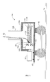
- Figure 3 is a side schematic illustration of an instrument removal system in accordance with an embodiment of the present invention.
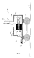
- Figure 4 is a side schematic illustration of the instrument removal system shown in Figure 3 with a detector cable partially coiled around a disposal spool.
- Figure 5 is a side schematic illustration of the instrument removal system shown in Figure 3 with the disposal spool being transferred to a disposal cask.
- Figure 6 is a side schematic illustration of the instrument removal system shown in Figure 3 with the disposal spool transferred to the disposal cask.
- An instrument removal system and method of removing detectors from a nuclear reactor is described in detail below. The system includes a removal cart that includes a disposal spool operatively coupled to a motor. A detector cable is coiled around the spool by rotating the spool with the motor, and then the disposal spool is transferred to a disposal cask for removal from the reactor. The removal system does not have a cable cutting process which eliminates loose chips and/or jammed cutters that need be cleared by personnel. The removal system utilizes existing under vessel equipment, for example, under vessel platform and rails, has low complexity with minimal operator interface resulting in lower personnel exposure to radiation.
- Referring to the drawings, Figure 1 is a sectional view, with parts cut away, of a boiling water nuclear reactor pressure vessel (RPV) 10. RPV 10 has a generally cylindrical shape and is closed at one end by a
bottom head 12 and at its other end by a removabletop head 14. A side-wall 16 extends frombottom head 12 totop head 14. Side-wall 16 includes atop flange 18.Top head 14 is attached totop flange 18. A cylindricallyshaped core shroud 20 surrounds areactor core 22. Shroud 20 is supported at one end by ashroud support 24 and includes aremovable shroud head 26 at the other end. Anannulus 28 is formed betweenshroud 20 and side-wall 16. Apump deck 30, which has a ring shape, extends betweenshroud support 24 and RPV side-wall 16.Pump deck 30 includes a plurality ofcircular openings 32, with each opening housing ajet pump 34.Jet pumps 34 are circumferentially distributed aroundcore shroud 20. Aninlet riser pipe 36 is coupled to twojet pumps 34 by atransition assembly 38. Eachjet pump 34 includes aninlet mixer 40, adiffuser 42, and atailpipe assembly 43.Inlet riser 36, which may be in the form of a pipe, and two connectedjet pumps 34 form ajet pump assembly 44. - Thermal power is generated within
core 22, which includesfuel assemblies 46 of fissionable material. Water circulated up throughcore 22 is at least partially converted to steam.Steam separators 48 separates steam from water, which is recirculated. Residual water is removed from the steam bysteam dryers 50. The steam exitsRPV 10 through asteam outlet 52 nearvessel top head 14. - The amount of thermal power generated in
core 22 is regulated by inserting and withdrawingcontrol rods 54 of neutron absorbing material, such as for example, boron carbide. To the extent thatcontrol rod 54 is inserted intocore 22 betweenfuel assemblies 46, it absorbs neutrons that would otherwise be available to promote the chain reaction which generates thermal power incore 22. Controlrod guide tubes 56 maintain the vertical motion ofcontrol rods 54 during insertion and withdrawal. Control rod drives 58 effect the insertion and withdrawal ofcontrol rods 54. Control rod drives 58 extend throughbottom head 12. -
Fuel assemblies 46 are aligned by acore plate 60 located at the base ofcore 22. Atop guide 62 aligns fuel bundles 46 as they are lowered intocore 22.Core plate 60 andtop guide 62 are supported bycore shroud 20.Pressure vessel 10 is mounted on a reinforcedconcrete pedestal 66. - Figure 2 is a sectional schematic illustration of an under
pressure vessel area 70 of nuclearreactor pressure vessel 10 enclosed bypedestal 66. Underpressure vessel area 70 includes awork platform 72 and transfer rails 74 that can be used for moving work equipment into undervessel area 70. - Referring to Figures 3-6, an
instrument removal system 80 for removingdetector cables 82 from nuclearreactor pressure vessel 10 includes, in an exemplary embodiment, aremoval cart 84 and adisposal cask 86.Removal cart 84 includes a base 88 with a plurality ofwheels 90 operatively coupled tobase 88.Wheels 90 permit removal cart to move along transfer rails 74. Amotor 92 mounted onbase 88, and adrive shaft 94 is operatively coupled tomotor 92.Motor 92 can be any suitable motor, for example, an electric motor, an hydraulic driven motor, and an air driven motor. Adisposal spool 96 is removably mounted ondrive shaft 94.Disposal spool 96 includes anotch 98 sized to receive an end ofdetector cable 82.Disposal spool 96 also includes aspiral groove 100 to facilitate coilingdetector cable 82 arounddisposal spool 96. - A
bearing block 102 is mounted onbase 88 withdrive shaft 94 extending through bearingblock 102. At least one air piston 104 (two shown) is mounted in bearingblock 102. Figures 3 and 4show air pistons 104 in a first, non-extended position, and Figures 5 and 6show air pistons 104 in an activated extended position. Ahousing 106 is mounted onbase 88 withdisposal spool 96,drive shaft 94, bearingblock 102, andair pistons 104 positioned insidehousing 106. Anentrance port 108 is located inhousing 106 to permitdetector cable 82 to enterhousing 106. In the exemplaryembodiment entrance port 108 is formed from a transparent tube to permit remote visual monitoring during detector removal. Adoor 110 is located in one side ofhousing 106 that permits removal ofdisposal spool 96 fromhousing 106 whendoor 110 is in an open position (shown in Figures 5 and 6). -
Disposal cask 86 includes amain body 114 having a receivingcavity 116 therein.Cavity 116 is sized to receive at least onedisposal spool 96. Anaccess door 118 permits access tocavity 116. Whendoor 118 is in an open position, a disposal spool can be transferred intocavity 116. Whendoor 118 is in a closed position,cavity 116 is sealed. A plurality ofwheels 120 are operatively coupled tomain body 114 to enabledisposal cask 86 to move along rails 74 in undervessel area 70. - In operation,
instrument removal system 80 is first positioned in underpressure vessel area 70. Particularly,removal cart 84 anddisposal cask 86 are wheeled into undervessel area 70, and then an end of adetector cable 82 is inserted intonotch 98 ofdisposal spool 96 inremoval cart 84.Air motor 92 is activated tocoil detector cable 82 ontodisposal spool 96. After the entire length ofdetector cable 82 is coiled ontodisposal spool 96,disposal spool 96 is transferred todisposal cask 86 by activatingair pistons 104 to pushdisposal spool 96off drive shaft 94, outdoor 106 and intodisposal cask 86 throughaccess door 118.Disposal cask 86 is then removed from undervessel area 70. - While the invention has been described in terms of various specific embodiments, those skilled in the art will recognize that the invention can be practiced with modification within the spirit and scope of the claims.
Claims (10)
- An instrument removal system (80) for removing detector cables (82) from a nuclear reactor, said instrument removal system comprising a removal cart (84) and a disposal cask (86), said removal cart comprising:a base (88) comprising a plurality of wheels (90, 120) coupled thereto;a motor (92) mounted on said base;a drive shaft (94) operatively coupled to said motor;a disposal spool (96) removably mounted on said drive shaft, said disposal spool comprising a notch (98) sized to receive the detector cable;a housing (106) mounted on said base, said housing enclosing said disposal spool;an entrance port (108) in said housing sized to permit the detector cable to enter said housing.
- An instrument removal system (80) in accordance with Claim 1 wherein said removal cart (84) further comprises:at least one air driven piston mounted inside said housing (106); anda door (110) in said housing sized to permit said at least one piston to push said disposal spool (96) out of said housing when said door is in an open position.
- An instrument removal system (80) in accordance with Claim 1 wherein said entrance port (108) comprises a transparent tube.
- An instrument removal system (80) in accordance with Claim 1 wherein said disposal spool (96) comprises a spiral groove (100) extending from a first end of said disposal spool to a second end of said disposal spool, said spiral groove sized to receive the detector cable (82).
- An instrument removal system (80) in accordance with Claim 1 wherein said motor (92) is an air driven motor.
- An instrument removal system (80) in accordance with Claim 1 wherein said disposal cask (86) comprises:a main body (114) having a cavity (116) therein sized to receive at least one disposal spool (96);an access door (118) in said main body that permits access to said cavity when said access door is in an open position; anda plurality of wheels (90,120) operatively coupled to said main body.
- A nuclear reactor comprising:a reactor pressure vessel (10);an under vessel platform positioned below said reactor pressure vessel;a plurality of transfer rails (74) positioned below said reactor pressure vessel;at least one detector cable (82) coupled to said reactor pressure vessel;an instrument removal system (80) operationally positioned on said transfer rails below said reactor pressure vessel, said instrument removal system comprising a removal cart (84) and a disposal cask (86), said removal cart comprising:a base (88) comprising a plurality of wheels (90, 120) coupled thereto;a motor (92) mounted on said base;a drive shaft (94) operatively coupled to said motor;a disposal spool (96) removably mounted on said drive shaft, said disposal spool comprising a notch (98) sized to receive said detector cable;a housing (106) mounted on said base, said housing enclosing said disposal spool;an entrance port (108) in said housing sized to permit the detector cable to enter said housing.
- A nuclear reactor in accordance with Claim 7 wherein said removal cart (84) further comprises:at least one air driven piston mounted inside said housing (106); anda door (110) in said housing sized to permit said at least one piston to push said disposal spool (96) out of said housing when said door is in an open position.
- A nuclear reactor in accordance with Claim 7 wherein said entrance port (108) comprises a transparent tube.
- A nuclear reactor in accordance with Claim 7 wherein said disposal spool (96) comprises a spiral groove (100) extending from a first end of said disposal spool to a second end of said disposal spool, said spiral groove sized to receive said detector cable (82).
Applications Claiming Priority (1)
| Application Number | Priority Date | Filing Date | Title |
|---|---|---|---|
| US11/313,904 US7835481B2 (en) | 2005-12-21 | 2005-12-21 | Instrument removal system |
Publications (1)
| Publication Number | Publication Date |
|---|---|
| EP1801813A1 true EP1801813A1 (en) | 2007-06-27 |
Family
ID=37873128
Family Applications (1)
| Application Number | Title | Priority Date | Filing Date |
|---|---|---|---|
| EP06126386A Withdrawn EP1801813A1 (en) | 2005-12-21 | 2006-12-18 | Instrument removal system |
Country Status (5)
| Country | Link |
|---|---|
| US (2) | US7835481B2 (en) |
| EP (1) | EP1801813A1 (en) |
| JP (1) | JP2007171188A (en) |
| CN (1) | CN1988050A (en) |
| TW (1) | TW200739606A (en) |
Families Citing this family (6)
| Publication number | Priority date | Publication date | Assignee | Title |
|---|---|---|---|---|
| US10758193B2 (en) | 2016-04-14 | 2020-09-01 | Hibrand Industries Ag | Medical radiation protector and production thereof |
| CN107767976B (en) * | 2017-10-17 | 2019-07-02 | 中国核动力研究设计院 | A kind of detector assembly dismounting technique and its dedicated dismounting equipment |
| CN107767972B (en) * | 2017-10-17 | 2019-10-01 | 中国核动力研究设计院 | A kind of reactor detector removes the capacity reducing component and its capacity reduction method of device |
| CN107742540B (en) * | 2017-10-17 | 2019-05-21 | 中国核动力研究设计院 | A kind of gripping apparatus and grasping means for detector assembly replacement |
| CN109830309B (en) * | 2019-02-20 | 2023-04-11 | 哈尔滨工程大学 | Separated nuclear reactor core |
| GB2583161A (en) * | 2019-12-06 | 2020-10-21 | Rolls Royce Plc | A containment system |
Citations (6)
| Publication number | Priority date | Publication date | Assignee | Title |
|---|---|---|---|---|
| US2853625A (en) * | 1945-08-13 | 1958-09-23 | Leo A Ohlinger | Discharge device for radioactive material |
| US3144218A (en) * | 1961-06-26 | 1964-08-11 | Gen Dynamics Corp | Transmission cable storing and positioning mechanism |
| JPS5447994A (en) | 1977-09-26 | 1979-04-16 | Toshiba Corp | Device for recovering detector in reactor |
| JPS62134598A (en) * | 1985-12-09 | 1987-06-17 | 株式会社東芝 | Winder for instrumentation cable |
| JPH07294689A (en) * | 1994-04-25 | 1995-11-10 | Toshiba Eng Co Ltd | Winding device for monitor detector disposal |
| JP2000338294A (en) * | 1999-05-31 | 2000-12-08 | Toshiba Corp | Cable winding device for neutron flux detector |
Family Cites Families (23)
| Publication number | Priority date | Publication date | Assignee | Title |
|---|---|---|---|---|
| US3136436A (en) * | 1960-10-07 | 1964-06-09 | Atwood E Erlinder | Container elevating and dumping mechanism for self-loading vehicle |
| US3353693A (en) * | 1966-01-18 | 1967-11-21 | Joy Mfg Co | Self-loading vehicle |
| DE1280432B (en) * | 1967-03-11 | 1968-10-17 | Siemens Ag | Arrangement for measuring and evaluating the activity of irradiated measuring probes |
| US3598966A (en) * | 1968-06-27 | 1971-08-10 | Ncr Co | Clock generation error-checking means |
| US3751333A (en) * | 1970-06-11 | 1973-08-07 | C Drummond | Nuclear reactor core monitoring system |
| FR2150115A5 (en) * | 1971-08-13 | 1973-03-30 | Gablin Kenneth | |
| US4313793A (en) * | 1979-10-22 | 1982-02-02 | Combustion Engineering, Inc. | Machine for removing in-core instrument assemblies from a nuclear reactor |
| US4583714A (en) * | 1980-03-26 | 1986-04-22 | Hy-Reel Machinery, Inc. | Vehicle mountable cable reel apparatus |
| GB8415734D0 (en) * | 1984-06-20 | 1984-07-25 | Bicc Plc | Coil forming method |
| FR2573236B1 (en) * | 1984-11-13 | 1987-07-17 | Framatome Sa | DEVICE FOR CLEANING THE GUIDING TUBES OF THE MEASUREMENTS OF NEUTRONIC FLOWS IN A NUCLEAR PRESSURE WATER REACTOR |
| FR2575874B1 (en) * | 1985-01-07 | 1987-03-20 | Framatome Sa | DEVICE FOR WINDING AND UNWINDING A CABLE WITH ONE END PROVIDING ELECTRICAL CONTACT WITH A FIXED INSTALLATION |
| JPS63306149A (en) * | 1987-05-30 | 1988-12-14 | Yoshida Kogyo Kk <Ykk> | Spool discharge method and its discharge device |
| US5421501A (en) * | 1991-01-16 | 1995-06-06 | Haines; Roger C. | Method and apparatus for cable dispensing and placement |
| US5388781A (en) * | 1991-01-30 | 1995-02-14 | Sauber; Charles J. | Cable pulling and reeling apparatus having anti-spill device and method |
| US5225114A (en) * | 1991-09-18 | 1993-07-06 | Chem-Nuclear Systems, Inc. | Multipurpose container for low-level radioactive waste |
| US5383714A (en) * | 1992-11-09 | 1995-01-24 | Hunter; H. Victor | Vehicle having dump bed |
| US5621776A (en) * | 1995-07-14 | 1997-04-15 | General Electric Company | Fault-tolerant reactor protection system |
| BR9610373A (en) * | 1995-08-22 | 1999-12-21 | Western Well Toll Inc | Traction-thrust hole tool |
| US5787137A (en) * | 1996-02-02 | 1998-07-28 | General Electric Company | Methods and apparatus for performing repairs and inspections in a reactor pressure vessel of a nuclear reactor |
| US5838751A (en) * | 1996-06-18 | 1998-11-17 | General Electric Company | Core plate repair using guide tube gap wedges |
| US5802127A (en) * | 1996-09-11 | 1998-09-01 | General Electric Company | Device for protecting in-core monitors against damage during servicing of nuclear reactor |
| US5988555A (en) * | 1998-04-02 | 1999-11-23 | Completed Design, Inc. | Cable winding machine |
| FR2837612B1 (en) * | 2002-03-22 | 2004-07-16 | Framatome Anp | METHOD AND DEVICE FOR REPLACING AND METHOD FOR REPAIRING A SECTION OF A PIPE OF THE PRIMARY CIRCUIT OF A NUCLEAR REACTOR |
-
2005
- 2005-12-21 US US11/313,904 patent/US7835481B2/en not_active Expired - Fee Related
-
2006
- 2006-12-14 TW TW095146928A patent/TW200739606A/en unknown
- 2006-12-18 EP EP06126386A patent/EP1801813A1/en not_active Withdrawn
- 2006-12-20 JP JP2006342130A patent/JP2007171188A/en not_active Withdrawn
- 2006-12-21 CN CNA2006101724468A patent/CN1988050A/en active Pending
-
2010
- 2010-10-15 US US12/905,634 patent/US7965807B2/en not_active Expired - Lifetime
Patent Citations (6)
| Publication number | Priority date | Publication date | Assignee | Title |
|---|---|---|---|---|
| US2853625A (en) * | 1945-08-13 | 1958-09-23 | Leo A Ohlinger | Discharge device for radioactive material |
| US3144218A (en) * | 1961-06-26 | 1964-08-11 | Gen Dynamics Corp | Transmission cable storing and positioning mechanism |
| JPS5447994A (en) | 1977-09-26 | 1979-04-16 | Toshiba Corp | Device for recovering detector in reactor |
| JPS62134598A (en) * | 1985-12-09 | 1987-06-17 | 株式会社東芝 | Winder for instrumentation cable |
| JPH07294689A (en) * | 1994-04-25 | 1995-11-10 | Toshiba Eng Co Ltd | Winding device for monitor detector disposal |
| JP2000338294A (en) * | 1999-05-31 | 2000-12-08 | Toshiba Corp | Cable winding device for neutron flux detector |
Also Published As
| Publication number | Publication date |
|---|---|
| US20110026662A1 (en) | 2011-02-03 |
| TW200739606A (en) | 2007-10-16 |
| CN1988050A (en) | 2007-06-27 |
| US20070140404A1 (en) | 2007-06-21 |
| JP2007171188A (en) | 2007-07-05 |
| US7835481B2 (en) | 2010-11-16 |
| US7965807B2 (en) | 2011-06-21 |
Similar Documents
| Publication | Publication Date | Title |
|---|---|---|
| US7965807B2 (en) | Instrument removal system | |
| EP2946390B1 (en) | Apparatus and method for removing the upper internals from a nuclear reactor pressurized vessel | |
| EP2725583B1 (en) | Radiation shielding method and apparatus, and method for processing nuclear reactor vessel | |
| EP3625804A1 (en) | Radioisotope production target insert design and target harvesting methodology for long term irradiation in commercial nuclear reactors | |
| CN110444304A (en) | A nuclear power plant core measurement instrument underwater replacement system and method | |
| US4313793A (en) | Machine for removing in-core instrument assemblies from a nuclear reactor | |
| US6418178B1 (en) | Control rod coupling assembly for a nuclear reactor | |
| CN112259267B (en) | Nuclear reactor detector assembly removal device | |
| US5173249A (en) | Flux thimble removal tool | |
| JP2007121255A (en) | Separation and storage device for spent nuclear fuel rods | |
| CN112489838A (en) | Extraction equipment and method for nuclear detection instrument assembly of reactor core | |
| JP2015502537A (en) | A device for vertically fragmenting control rod blades in boiling water reactors. | |
| US5227123A (en) | Core instrument cutting system | |
| EP2481057B1 (en) | Control rod drive outer filter removal tool | |
| EP3642850B1 (en) | System and method for volume reduction of nuclear reactor components | |
| JP6446370B2 (en) | System and method for disposing of one or more radioactive parts from a nuclear power plant reactor | |
| JPS61288200A (en) | Overhaul machine for nuclear reactor, function thereof is released | |
| CN115389248B (en) | A water pool sampling device | |
| CN212762832U (en) | Electric grinding box for safety valve core | |
| CA3066142C (en) | System and method for volume reduction of nuclear reactor components | |
| CN119964860B (en) | A nuclear reactor detector assembly recovery system and method | |
| CN223598419U (en) | Nuclear reactor detector assembly shielding device and recovery system | |
| RU92565U1 (en) | DEVICE FOR REMOVING A CONTAINER ASSEMBLY WITH IRRADIATED BODY WITNESS SAMPLES FROM THE HOUSING OF THE NUCLEAR REACTOR | |
| JPH07294689A (en) | Winding device for monitor detector disposal | |
| JP5111587B2 (en) | How to store radioactive waste |
Legal Events
| Date | Code | Title | Description |
|---|---|---|---|
| PUAI | Public reference made under article 153(3) epc to a published international application that has entered the european phase |
Free format text: ORIGINAL CODE: 0009012 |
|
| AK | Designated contracting states |
Kind code of ref document: A1 Designated state(s): AT BE BG CH CY CZ DE DK EE ES FI FR GB GR HU IE IS IT LI LT LU LV MC NL PL PT RO SE SI SK TR |
|
| AX | Request for extension of the european patent |
Extension state: AL BA HR MK YU |
|
| 17P | Request for examination filed |
Effective date: 20071227 |
|
| 17Q | First examination report despatched |
Effective date: 20080201 |
|
| AKX | Designation fees paid |
Designated state(s): CH DE ES LI SE |
|
| STAA | Information on the status of an ep patent application or granted ep patent |
Free format text: STATUS: THE APPLICATION IS DEEMED TO BE WITHDRAWN |
|
| 18D | Application deemed to be withdrawn |
Effective date: 20100701 |