EP1801566A1 - Gas temperature stabilisation for gas analyser - Google Patents
Gas temperature stabilisation for gas analyser Download PDFInfo
- Publication number
- EP1801566A1 EP1801566A1 EP05270101A EP05270101A EP1801566A1 EP 1801566 A1 EP1801566 A1 EP 1801566A1 EP 05270101 A EP05270101 A EP 05270101A EP 05270101 A EP05270101 A EP 05270101A EP 1801566 A1 EP1801566 A1 EP 1801566A1
- Authority
- EP
- European Patent Office
- Prior art keywords
- gas
- temperature
- heating element
- gas flow
- ptc
- Prior art date
- Legal status (The legal status is an assumption and is not a legal conclusion. Google has not performed a legal analysis and makes no representation as to the accuracy of the status listed.)
- Withdrawn
Links
- 230000006641 stabilisation Effects 0.000 title 1
- 238000010521 absorption reaction Methods 0.000 claims abstract description 12
- 238000010438 heat treatment Methods 0.000 claims abstract description 12
- 239000000919 ceramic Substances 0.000 claims abstract description 10
- 230000003750 conditioning effect Effects 0.000 claims description 11
- 238000000034 method Methods 0.000 claims description 8
- 230000003466 anti-cipated effect Effects 0.000 claims description 2
- 230000001143 conditioned effect Effects 0.000 abstract 1
- 239000007789 gas Substances 0.000 description 25
- 238000004088 simulation Methods 0.000 description 6
- 238000005259 measurement Methods 0.000 description 4
- 230000001413 cellular effect Effects 0.000 description 1
- 229910010293 ceramic material Inorganic materials 0.000 description 1
- 238000005253 cladding Methods 0.000 description 1
- 230000005494 condensation Effects 0.000 description 1
- 238000009833 condensation Methods 0.000 description 1
- 230000001419 dependent effect Effects 0.000 description 1
- 230000009977 dual effect Effects 0.000 description 1
- 230000000694 effects Effects 0.000 description 1
- 239000003344 environmental pollutant Substances 0.000 description 1
- 239000011521 glass Substances 0.000 description 1
- 238000009413 insulation Methods 0.000 description 1
- 239000012774 insulation material Substances 0.000 description 1
- 239000000463 material Substances 0.000 description 1
- 231100000719 pollutant Toxicity 0.000 description 1
- 230000003019 stabilising effect Effects 0.000 description 1
- XLYOFNOQVPJJNP-UHFFFAOYSA-N water Substances O XLYOFNOQVPJJNP-UHFFFAOYSA-N 0.000 description 1
Images

Classifications
-
- G—PHYSICS
- G01—MEASURING; TESTING
- G01N—INVESTIGATING OR ANALYSING MATERIALS BY DETERMINING THEIR CHEMICAL OR PHYSICAL PROPERTIES
- G01N21/00—Investigating or analysing materials by the use of optical means, i.e. using sub-millimetre waves, infrared, visible or ultraviolet light
- G01N21/01—Arrangements or apparatus for facilitating the optical investigation
- G01N21/03—Cuvette constructions
- G01N21/0332—Cuvette constructions with temperature control
-
- G—PHYSICS
- G01—MEASURING; TESTING
- G01N—INVESTIGATING OR ANALYSING MATERIALS BY DETERMINING THEIR CHEMICAL OR PHYSICAL PROPERTIES
- G01N21/00—Investigating or analysing materials by the use of optical means, i.e. using sub-millimetre waves, infrared, visible or ultraviolet light
- G01N21/17—Systems in which incident light is modified in accordance with the properties of the material investigated
- G01N21/25—Colour; Spectral properties, i.e. comparison of effect of material on the light at two or more different wavelengths or wavelength bands
- G01N21/31—Investigating relative effect of material at wavelengths characteristic of specific elements or molecules, e.g. atomic absorption spectrometry
- G01N21/35—Investigating relative effect of material at wavelengths characteristic of specific elements or molecules, e.g. atomic absorption spectrometry using infrared light
- G01N21/3504—Investigating relative effect of material at wavelengths characteristic of specific elements or molecules, e.g. atomic absorption spectrometry using infrared light for analysing gases, e.g. multi-gas analysis
Definitions
- This invention relates to a device and a method for stabilising and conditioning gas before the gas is analysed in a device such as an IR absorption cell.
- a further factor limiting the accuracy of existing on-vehicle IR absorption measurement is that e gas flow in the measurement cell is not uniform. It is conventional for the measurement cell to be a cylinder with end windows, and the gas entrance and exit are off-axis. This leads to parts of the cell having areas of stagnant gas, which impacts on measurement accuracy.
- the present invention provides a device for conditioning a gas flow to an infrared absorption cell, the device comprising a positive temperature co-efficient (PTC) heating element having multiple parallel gas flow channels.
- PTC positive temperature co-efficient
- the invention provides a method of conditioning a gas flow to an infrared absorption cell, comprising passing the gas flow through a PTC heating element having multiple parallel gas flow channels.
- the heating element is a ceramic honeycomb PTC heating element.
- exhaust gases are bled off from an exhaust conduit 10 and passed through an infrared absorption cell 12 of known type, having a light source 14 and detector 16 operating via end windows of the cell 12.
- a gas conditioning device 18 is interposed between the exhaust conduit 10 and the measuring cell 12.
- the device 18 comprises a ceramic honeycomb PTC element 20 providing a multiplicity of parallel gas flow channels extending between an inlet manifold 22 and an outlet manifold 24. Opposite faces of the ceramic PTC element 20 are connected to opposite poles of a suitable voltage supply V.
- a typical characteristic being shown in Fig. 3 the resistance rises and current falls with increasing gas temperature.
- the exit temperature of the gas is self-limiting, the maximum temperature being determined by the ceramic material used.
- a typical target gas temperature is about 110-130oC, preferably about 120oC. This is particularly preferred, as being the least temperature that safeguards against water condensation in the measuring cell while minimising thermal effects on the electronics.
- the exhaust gas entering the conditioning device 18 will typically have a temperature about 70oC, but this can vary widely. More importantly, the gas temperature can be highly non-uniform within the flow, and the physical arrangement of the flow conduits and the measuring cell can accentuate a non-uniform atmosphere within the cell.
- the conditioning device of the present invention serves the dual purpose of providing a constant temperature regardless of engine operating conditions, and providing a gas flow within the cell with a greatly enhanced uniformity of temperature distribution.
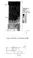
- Fig. 4 shows the results of a simulation of the temperatures achieved within a device embodying the invention.
- the simulation is of one-quarter of an arrangement in which a cylindrical conduit 40 communicates with a rectangular conditioning device 18; see also Fig. 5, in which the area of the simulation is shaded.
- a cylindrical conduit 40 communicates with a rectangular conditioning device 18; see also Fig. 5, in which the area of the simulation is shaded.
- the temperature distribution across the inlet manifold 22 is significantly non-uniform. This causes the gas temperatures in the various flow passages 20 increase at different rates, but all reach the target temperature within a relatively short length, and the outlet temperature distribution is highly uniform.
- the passage length in the PTC heater is over-dimensioned, i.e. significantly longer than the point at which the temperature could be expected to reach a self-limiting value.
- the passage length is chosen such that in normal operation the target temperature is reached in less than half the passage length. This feature ensures stability and uniformity under varying operating conditions.
- the length should also be chosen such that the target temperature will be attained within that length even under the worst anticipated inlet condition, which in automotive use is typically taken to be a cold start at an ambient temperature of -40oC
- the simulation of Fig. 4 is for a gas flow of 5 1/min and an entrance temperature of 70oC.
- the target temperature of 120oC is reached in a length of only about 20mm.
- Ceramic honeycomb PTC elements are well known per se. However, those which are currently commercially available are designed primarily for providing a space heater in minimum volume. They therefore operate at a higher temperature than is typical for the present invention. The design of a ceramic honeycomb PTC heater meeting parameters such as those discussed above, by appropriate choice of materials and dimensions, will be readily apparent to a person of ordinary skill in the relevant art.
- the operation of the gas conditioning device and the absorption cell 12 may be further improved by cladding either or both with thermal insulation.
- a particularly preferred insulation material is FoamGlas® cellular glass by Pittsburgh Corning.
Landscapes
- Physics & Mathematics (AREA)
- Health & Medical Sciences (AREA)
- Life Sciences & Earth Sciences (AREA)
- Chemical & Material Sciences (AREA)
- Analytical Chemistry (AREA)
- Biochemistry (AREA)
- General Health & Medical Sciences (AREA)
- General Physics & Mathematics (AREA)
- Immunology (AREA)
- Pathology (AREA)
- Spectroscopy & Molecular Physics (AREA)
- Investigating Or Analysing Materials By Optical Means (AREA)
- Exhaust Gas After Treatment (AREA)
Abstract
Gas flow from a source such as an exhaust line (10) to an analyser such as an infrared absorption cell (12) is conditioned by a device (18) having a heating means with a positive temperature coefficient (PTC). The heating means may be a ceramic honeycomb PTC heater. Gas entering the analyser is at a constant temperature having a high degree of uniformity throughout the flow area.
Description
- This invention relates to a device and a method for stabilising and conditioning gas before the gas is analysed in a device such as an IR absorption cell.
- It is know to use IR absorption techniques to measure pollutants in vehicle emissions. However, the accuracy of such techniques is highly dependent on knowing the temperature and pressure of the exhaust gas, as these parameters have a significant impact on the measuring signal.
- A further factor limiting the accuracy of existing on-vehicle IR absorption measurement is that e gas flow in the measurement cell is not uniform. It is conventional for the measurement cell to be a cylinder with end windows, and the gas entrance and exit are off-axis. This leads to parts of the cell having areas of stagnant gas, which impacts on measurement accuracy.
- The present invention provides a device for conditioning a gas flow to an infrared absorption cell, the device comprising a positive temperature co-efficient (PTC) heating element having multiple parallel gas flow channels.
- From another aspect, the invention provides a method of conditioning a gas flow to an infrared absorption cell, comprising passing the gas flow through a PTC heating element having multiple parallel gas flow channels.
- Preferably, the heating element is a ceramic honeycomb PTC heating element.
- Further preferred features and advantages of the invention will be apparent from the following description and the claims.
- An embodiment of the invention will now be described, by way of example only, with reference to the drawings, in which:
- Fig. 1 is a schematic representation of an exhaust sensor system including one embodiment of a device of the present invention;
- Fig. 2 shows an example of a honeycomb heater element;
- Fig. 3 is a graph of a typical resistance-temperature characteristic of a PTC ceramic;
- Fig. 4 shows a simulation of gas temperature profile within one-quarter of a device of the present invention; and
- Fig. 5 is an end view of the simulated device of Fig. 4, showing the area of the simulation shaded.
- Referring to Fig. 1, exhaust gases are bled off from an
exhaust conduit 10 and passed through an infrared absorption cell 12 of known type, having alight source 14 and detector 16 operating via end windows of the cell 12. - A
gas conditioning device 18 is interposed between theexhaust conduit 10 and the measuring cell 12. Thedevice 18 comprises a ceramichoneycomb PTC element 20 providing a multiplicity of parallel gas flow channels extending between aninlet manifold 22 and anoutlet manifold 24. Opposite faces of theceramic PTC element 20 are connected to opposite poles of a suitable voltage supply V. - Because of the positive temperature coefficient of resistance of such elements, a typical characteristic being shown in Fig. 3, the resistance rises and current falls with increasing gas temperature. Thus the exit temperature of the gas is self-limiting, the maximum temperature being determined by the ceramic material used. For IR absorption analysis of exhaust gas in an automotive application, a typical target gas temperature is about 110-130ºC, preferably about 120ºC. This is particularly preferred, as being the least temperature that safeguards against water condensation in the measuring cell while minimising thermal effects on the electronics.
- The exhaust gas entering the
conditioning device 18 will typically have a temperature about 70ºC, but this can vary widely. More importantly, the gas temperature can be highly non-uniform within the flow, and the physical arrangement of the flow conduits and the measuring cell can accentuate a non-uniform atmosphere within the cell. The conditioning device of the present invention serves the dual purpose of providing a constant temperature regardless of engine operating conditions, and providing a gas flow within the cell with a greatly enhanced uniformity of temperature distribution. - Fig. 4 shows the results of a simulation of the temperatures achieved within a device embodying the invention. The simulation is of one-quarter of an arrangement in which a
cylindrical conduit 40 communicates with arectangular conditioning device 18; see also Fig. 5, in which the area of the simulation is shaded. It will be noted that the temperature distribution across theinlet manifold 22 is significantly non-uniform. This causes the gas temperatures in thevarious flow passages 20 increase at different rates, but all reach the target temperature within a relatively short length, and the outlet temperature distribution is highly uniform. - It is a preferred feature of the invention that the passage length in the PTC heater is over-dimensioned, i.e. significantly longer than the point at which the temperature could be expected to reach a self-limiting value. Preferably the passage length is chosen such that in normal operation the target temperature is reached in less than half the passage length. This feature ensures stability and uniformity under varying operating conditions. The length should also be chosen such that the target temperature will be attained within that length even under the worst anticipated inlet condition, which in automotive use is typically taken to be a cold start at an ambient temperature of -40ºC
- The simulation of Fig. 4 is for a gas flow of 5 1/min and an entrance temperature of 70ºC. The target temperature of 120ºC is reached in a length of only about 20mm.
- Ceramic honeycomb PTC elements are well known per se. However, those which are currently commercially available are designed primarily for providing a space heater in minimum volume. They therefore operate at a higher temperature than is typical for the present invention. The design of a ceramic honeycomb PTC heater meeting parameters such as those discussed above, by appropriate choice of materials and dimensions, will be readily apparent to a person of ordinary skill in the relevant art.
- The operation of the gas conditioning device and the absorption cell 12 may be further improved by cladding either or both with thermal insulation. A particularly preferred insulation material is FoamGlas® cellular glass by Pittsburgh Corning.
Claims (10)
- A device for conditioning a gas flow to an infrared absorption cell, the device comprising a positive temperature co-efficient (PTC) heating element having multiple parallel gas flow channels.
- A device according to claim 1, in which the heating element is a ceramic honeycomb PTC heating element.
- A device according to claim 1 or claim 2, including an inlet manifold and an outlet manifold each communicating with said channels.
- A device according to any preceding claim, in which the device is adapted to give a gas outlet temperature of 110-130ºC.
- A device according to any preceding claim, in which the length of said channels is such that the desired gas outlet temperature is attained under the worst anticipated inlet condition.
- A method of conditioning a gas flow to an infrared absorption cell, comprising passing the gas flow through a PTC heating element having multiple parallel gas flow channels.
- A method according to claim 6, in which the heating element is a ceramic honeycomb PTC heating element.
- A method according to claim 6 or claim 7, in which the gas is raised to an outlet gas temperature of 110-130ºC.
- A method according to any of claims 6 to 8, in which the gas outlet temperature is attained with an inlet gas temperature down to -40ºC.
- Use of a positive temperature coefficient ceramic honeycomb heater element for conditioning a flow of exhaust gas to an infrared absorption cell.
Priority Applications (1)
| Application Number | Priority Date | Filing Date | Title |
|---|---|---|---|
| EP05270101A EP1801566A1 (en) | 2005-12-22 | 2005-12-22 | Gas temperature stabilisation for gas analyser |
Applications Claiming Priority (1)
| Application Number | Priority Date | Filing Date | Title |
|---|---|---|---|
| EP05270101A EP1801566A1 (en) | 2005-12-22 | 2005-12-22 | Gas temperature stabilisation for gas analyser |
Publications (1)
| Publication Number | Publication Date |
|---|---|
| EP1801566A1 true EP1801566A1 (en) | 2007-06-27 |
Family
ID=35789029
Family Applications (1)
| Application Number | Title | Priority Date | Filing Date |
|---|---|---|---|
| EP05270101A Withdrawn EP1801566A1 (en) | 2005-12-22 | 2005-12-22 | Gas temperature stabilisation for gas analyser |
Country Status (1)
| Country | Link |
|---|---|
| EP (1) | EP1801566A1 (en) |
Citations (4)
| Publication number | Priority date | Publication date | Assignee | Title |
|---|---|---|---|---|
| GB1242482A (en) * | 1968-09-18 | 1971-08-11 | Beckman Instruments Inc | Improvements in or relating to exhaust gas analysis |
| US4050823A (en) * | 1974-09-05 | 1977-09-27 | Dragerwerk Aktiengesellschaft | Apparatus for continuously measuring the CO2 content in breathing gases |
| US4264888A (en) * | 1979-05-04 | 1981-04-28 | Texas Instruments Incorporated | Multipassage resistor and method of making |
| JPH06323129A (en) * | 1993-05-14 | 1994-11-22 | Osaka Cement Co Ltd | Exhaust gas treatment filter for diesel engine |
-
2005
- 2005-12-22 EP EP05270101A patent/EP1801566A1/en not_active Withdrawn
Patent Citations (4)
| Publication number | Priority date | Publication date | Assignee | Title |
|---|---|---|---|---|
| GB1242482A (en) * | 1968-09-18 | 1971-08-11 | Beckman Instruments Inc | Improvements in or relating to exhaust gas analysis |
| US4050823A (en) * | 1974-09-05 | 1977-09-27 | Dragerwerk Aktiengesellschaft | Apparatus for continuously measuring the CO2 content in breathing gases |
| US4264888A (en) * | 1979-05-04 | 1981-04-28 | Texas Instruments Incorporated | Multipassage resistor and method of making |
| JPH06323129A (en) * | 1993-05-14 | 1994-11-22 | Osaka Cement Co Ltd | Exhaust gas treatment filter for diesel engine |
Non-Patent Citations (1)
| Title |
|---|
| PATENT ABSTRACTS OF JAPAN vol. 1995, no. 02 31 March 1995 (1995-03-31) * |
Similar Documents
| Publication | Publication Date | Title |
|---|---|---|
| CN1985163B (en) | Measurement sensor | |
| JP6918228B2 (en) | Devices and methods for determining the heating temperature of the heating elements of electrically heatable catalytic converters and automobiles | |
| US8201993B2 (en) | Method for operating a gas sensor | |
| US6453724B1 (en) | Gas concentration sensing apparatus | |
| KR937000758A (en) | Method and apparatus for monitoring the operation of catalytic converter of internal combustion engine | |
| US3593023A (en) | Apparatus and method for exhaust analysis | |
| EP0347571A2 (en) | Method of determining the thermal conduction coefficient of a material, and instrument for the measurement of same | |
| KR101332923B1 (en) | System for determining exhaust gas volume | |
| US8623187B2 (en) | Gas sensor | |
| JP2010525344A (en) | Sheet resistance in the exhaust pipe | |
| AU2003287960A1 (en) | Method and device for determining a characteristic value that is representative of the condition of a gas | |
| US20120192619A1 (en) | Flow Sensors Having a Flow Duct in the Cover, and Sensor Tip as Intermediate Product | |
| WO2003083464A1 (en) | Temperature control device for exhaust gas sensor and temperature control method for the sensor | |
| CA2493526A1 (en) | Apparatus and method for controllably affecting the temperature of faims components | |
| EP3407051B1 (en) | Exhaust gas analysis apparatus and exhaust gas analysis method | |
| JP2001509600A (en) | Equipment for measuring relative atmospheric humidity | |
| US20070137298A1 (en) | Heated H2 sensor | |
| US6085575A (en) | Process for the determination of the exhaust gas temperature and of the air/fuel ratio lambda and a sensor arrangement for execution of the process | |
| US4949578A (en) | Flow metering of high temperature gases | |
| US4667105A (en) | Infrared radiation gas analyzer with PTC resistance heater | |
| WO2007063114A3 (en) | Device for determining and/or monitoring the mass flow rate of a gaseous medium | |
| JP2958866B2 (en) | Method and apparatus for detecting enthalpy difference | |
| US5024532A (en) | Dew point measuring apparatus installation system | |
| RU2117278C1 (en) | Hygrometer | |
| CN108885188A (en) | Method and apparatus for determining the concentration of the gas componant in admixture of gas |
Legal Events
| Date | Code | Title | Description |
|---|---|---|---|
| PUAI | Public reference made under article 153(3) epc to a published international application that has entered the european phase |
Free format text: ORIGINAL CODE: 0009012 |
|
| AK | Designated contracting states |
Kind code of ref document: A1 Designated state(s): AT BE BG CH CY CZ DE DK EE ES FI FR GB GR HU IE IS IT LI LT LU LV MC NL PL PT RO SE SI SK TR |
|
| AX | Request for extension of the european patent |
Extension state: AL BA HR MK YU |
|
| STAA | Information on the status of an ep patent application or granted ep patent |
Free format text: STATUS: THE APPLICATION HAS BEEN WITHDRAWN |
|
| 17P | Request for examination filed |
Effective date: 20070705 |
|
| 18W | Application withdrawn |
Effective date: 20070808 |