EP1801351A2 - Turbine blade tip cooling - Google Patents
Turbine blade tip cooling Download PDFInfo
- Publication number
- EP1801351A2 EP1801351A2 EP06256420A EP06256420A EP1801351A2 EP 1801351 A2 EP1801351 A2 EP 1801351A2 EP 06256420 A EP06256420 A EP 06256420A EP 06256420 A EP06256420 A EP 06256420A EP 1801351 A2 EP1801351 A2 EP 1801351A2
- Authority
- EP
- European Patent Office
- Prior art keywords
- spanwise
- trunk
- passageway
- cavity
- tip
- Prior art date
- Legal status (The legal status is an assumption and is not a legal conclusion. Google has not performed a legal analysis and makes no representation as to the accuracy of the status listed.)
- Granted
Links
Images

Classifications
-
- F—MECHANICAL ENGINEERING; LIGHTING; HEATING; WEAPONS; BLASTING
- F01—MACHINES OR ENGINES IN GENERAL; ENGINE PLANTS IN GENERAL; STEAM ENGINES
- F01D—NON-POSITIVE DISPLACEMENT MACHINES OR ENGINES, e.g. STEAM TURBINES
- F01D5/00—Blades; Blade-carrying members; Heating, heat-insulating, cooling or antivibration means on the blades or the members
- F01D5/12—Blades
- F01D5/14—Form or construction
- F01D5/18—Hollow blades, i.e. blades with cooling or heating channels or cavities; Heating, heat-insulating or cooling means on blades
- F01D5/187—Convection cooling
-
- F—MECHANICAL ENGINEERING; LIGHTING; HEATING; WEAPONS; BLASTING
- F01—MACHINES OR ENGINES IN GENERAL; ENGINE PLANTS IN GENERAL; STEAM ENGINES
- F01D—NON-POSITIVE DISPLACEMENT MACHINES OR ENGINES, e.g. STEAM TURBINES
- F01D5/00—Blades; Blade-carrying members; Heating, heat-insulating, cooling or antivibration means on the blades or the members
- F01D5/12—Blades
- F01D5/14—Form or construction
- F01D5/18—Hollow blades, i.e. blades with cooling or heating channels or cavities; Heating, heat-insulating or cooling means on blades
-
- B—PERFORMING OPERATIONS; TRANSPORTING
- B22—CASTING; POWDER METALLURGY
- B22C—FOUNDRY MOULDING
- B22C9/00—Moulds or cores; Moulding processes
- B22C9/10—Cores; Manufacture or installation of cores
-
- B—PERFORMING OPERATIONS; TRANSPORTING
- B22—CASTING; POWDER METALLURGY
- B22C—FOUNDRY MOULDING
- B22C9/00—Moulds or cores; Moulding processes
- B22C9/10—Cores; Manufacture or installation of cores
- B22C9/103—Multipart cores
-
- F—MECHANICAL ENGINEERING; LIGHTING; HEATING; WEAPONS; BLASTING
- F01—MACHINES OR ENGINES IN GENERAL; ENGINE PLANTS IN GENERAL; STEAM ENGINES
- F01D—NON-POSITIVE DISPLACEMENT MACHINES OR ENGINES, e.g. STEAM TURBINES
- F01D5/00—Blades; Blade-carrying members; Heating, heat-insulating, cooling or antivibration means on the blades or the members
- F01D5/02—Blade-carrying members, e.g. rotors
- F01D5/08—Heating, heat-insulating or cooling means
-
- F—MECHANICAL ENGINEERING; LIGHTING; HEATING; WEAPONS; BLASTING
- F01—MACHINES OR ENGINES IN GENERAL; ENGINE PLANTS IN GENERAL; STEAM ENGINES
- F01D—NON-POSITIVE DISPLACEMENT MACHINES OR ENGINES, e.g. STEAM TURBINES
- F01D5/00—Blades; Blade-carrying members; Heating, heat-insulating, cooling or antivibration means on the blades or the members
- F01D5/12—Blades
- F01D5/14—Form or construction
- F01D5/18—Hollow blades, i.e. blades with cooling or heating channels or cavities; Heating, heat-insulating or cooling means on blades
- F01D5/186—Film cooling
-
- F—MECHANICAL ENGINEERING; LIGHTING; HEATING; WEAPONS; BLASTING
- F01—MACHINES OR ENGINES IN GENERAL; ENGINE PLANTS IN GENERAL; STEAM ENGINES
- F01D—NON-POSITIVE DISPLACEMENT MACHINES OR ENGINES, e.g. STEAM TURBINES
- F01D5/00—Blades; Blade-carrying members; Heating, heat-insulating, cooling or antivibration means on the blades or the members
- F01D5/12—Blades
- F01D5/14—Form or construction
- F01D5/20—Specially-shaped blade tips to seal space between tips and stator
-
- F—MECHANICAL ENGINEERING; LIGHTING; HEATING; WEAPONS; BLASTING
- F05—INDEXING SCHEMES RELATING TO ENGINES OR PUMPS IN VARIOUS SUBCLASSES OF CLASSES F01-F04
- F05D—INDEXING SCHEME FOR ASPECTS RELATING TO NON-POSITIVE-DISPLACEMENT MACHINES OR ENGINES, GAS-TURBINES OR JET-PROPULSION PLANTS
- F05D2230/00—Manufacture
- F05D2230/20—Manufacture essentially without removing material
- F05D2230/21—Manufacture essentially without removing material by casting
-
- F—MECHANICAL ENGINEERING; LIGHTING; HEATING; WEAPONS; BLASTING
- F05—INDEXING SCHEMES RELATING TO ENGINES OR PUMPS IN VARIOUS SUBCLASSES OF CLASSES F01-F04
- F05D—INDEXING SCHEME FOR ASPECTS RELATING TO NON-POSITIVE-DISPLACEMENT MACHINES OR ENGINES, GAS-TURBINES OR JET-PROPULSION PLANTS
- F05D2230/00—Manufacture
- F05D2230/80—Repairing, retrofitting or upgrading methods
-
- F—MECHANICAL ENGINEERING; LIGHTING; HEATING; WEAPONS; BLASTING
- F05—INDEXING SCHEMES RELATING TO ENGINES OR PUMPS IN VARIOUS SUBCLASSES OF CLASSES F01-F04
- F05D—INDEXING SCHEME FOR ASPECTS RELATING TO NON-POSITIVE-DISPLACEMENT MACHINES OR ENGINES, GAS-TURBINES OR JET-PROPULSION PLANTS
- F05D2260/00—Function
- F05D2260/20—Heat transfer, e.g. cooling
- F05D2260/202—Heat transfer, e.g. cooling by film cooling
Definitions
- the invention relates to gas turbine engines. More particularly, the invention relates to cooled gas turbine engine blades.
- Blades are commonly formed with a cooling passageway network.
- a typical network receives cooling air through the blade platform.
- the cooling air is passed through convoluted paths through the airfoil, with at least a portion exiting the blade through apertures in the airfoil.
- These apertures may include holes (e.g., "film holes") distributed along the pressure and suction side surfaces of the airfoil and holes at junctions of those surfaces at leading and trailing edges. Additional apertures may be located at the blade tip.
- a principal portion of the blade is formed by a casting and machining process. During the casting process a sacrificial core is utilized to form at least main portions of the cooling passageway network.
- US Patent No. 6,824,359 discloses cooling air outlet passageways fanned along a trailing tip region of the airfoil.
- US Pregrant Publication No. 2004/0146401 discloses direction of air through a relief in a wall of a tip pocket to cool a trailing tip portion.
- US Patent No. 6,974,308 discloses use of a tip flag passageway to deliver a high volume of cooling air to a trailing tip portion.
- One aspect of the invention involves a turbine engine blade having an attachment root, a platform outboard of the attachment root, and an airfoil extending from the platform.
- the airfoil has pressure and suction sides extending between leading and trailing edges.
- An internal cooling passageway network includes at least one inlet in the root and a plurality of outlets along the airfoil.
- the passageway network includes a leading spanwise cavity fed by a first trunk.
- a streamwise cavity is inboard of a tip of the airfoil.
- a spanwise feed cavity feeds the streamwise cavity absent down-pass.
- a second trunk feeds the spanwise feed cavity.
- a second aspect of the invention involves a method for cooling a turbine engine blade airfoil comprising: passing a plurality of trunk airflows into the airfoil; and passing an airflow of said trunk airflows into a streamwise cavity inboard of the tip absent down-pass and with 0-20% diversion.
- a third aspect of the invention involves a casting core for forming a turbine engine blade and comprising: a root end and a tip end; a pressure side and a suction side; a leading spanwise portion; a first trunk portion; means linking the first trunk portion and the leading spanwise portion; a streamwise elongate portion inboard of the tip; a second trunk portion; and means noncircuitiously linking the second trunk portion and the streamwise elongate portion.
- a fourth aspect of the invention involves a method for engineering a turbine engine blade comprising: determining an aerodynamic heating distribution; and positioning a feed passageway for a streamwise tip passageway to as to avoid an undesired heating of cooling air delivered to the tip passageway through the feed passageway.
- a fifth aspect of the invention involves a method for remanufacturing a turbine engine or reengineering a configuration of said turbine engine, the remanufacturing or reengineering being from a baseline configuration to a final configuration and comprising: reconfiguring a cooling passageway system of a blade from a baseline configuration to a final configuration so as to at least one of: reduce an operational air temperature increase at a downstream end of a spanwise feed passageway relative to a blade inlet temperature, the spanwise feed passageway feeding a streamwise elongate tip end passageway; and provide a dedicated passageway trunk to feed a final configuration spanwise feed passageway feeding a final configuration streamwise elongate tip end passageway whereas the blade baseline configuration has one fewer passageway trunks and a baseline configuration spanwise feed passageway feeding a baseline configuration streamwise elongate tip end passageway is fed by a trunk shared with another spanwise passageway.
- FIG. 1 shows a blade 20 (e.g., an HPT blade) having an airfoil 22 extending along a span from an inboard end 24 to an outboard tip 26.
- the blade has leading and trailing edges 30 and 32 and pressure and suction sides 34 and 36.
- a tip compartment 38 may be formed recessed below a remaining portion of the tip 26.
- a platform 40 is formed at the inboard end 24 of the airfoil and locally forms an inboard extreme.of a core flowpath through the engine.
- a convoluted so-called "fir tree" attachment root 42 depends from the underside of the platform 40 for attaching the blade to a separate disk.
- One or more ports 44 may be formed in an inboard end of the root 42 for admitting cooling air to the blade. The cooling air may pass through a passageway system and exit through a number of outlets along the airfoil.
- the blade 40 may be representative of many existing or yet-developed blade configurations. Additionally, the principles discussed below may be applied to other blade configurations.
- FIG. 2 shows an exemplary prior art core 60 used to cast major portions of a passageway system of a prior art blade.
- the exemplary core 60 may be formed of one or more molded ceramic pieces assembled to each other or to additional components such as refractory metal cores.
- core directions are identified relative to associated directions of the resulting blade cast using the core.
- core portions may be identified with names corresponding to associated passageway portions formed when those core portions are removed from a casting. Additional passageway portions may be drilled or otherwise machined.
- the core 60 extends from an inboard end 62 to an outboard/tip end 64.
- Three trunks 66, 68, and 70 extend tipward from the inboard end 62.
- the trunks extend within the root of the resulting blade and form associated passageway trunks.
- the trunks may be joined at the inboard end (typically in a portion of the core that is embedded in a casting shell and falls outside the blade root).
- the leading trunk 66 joins/feeds a first spanwise feed passageway portion 80 extending to a tip end 82.
- the feed passageway portion 80 is connected to a leading edge impingement chamber/cavity portion 84.
- the cavity cast by the portion 84 may be impingement fed by airflow from the feed passageway cast by the portion 80, the air passing through a series of apertures cast by connecting posts 86. The cavity may then cool a leading edge portion of the airfoil via drilled or cast outlet holes.
- the second trunk 68 joins a spanwise passageway portion 90 having a distal end merged with a proximal end of streamwise extending portion 92.
- the portion 92 is a tip flag portion and the portion 90 is a flagpole portion.
- the flag portion 92 extends downstream toward the trailing edge adjacent the tip end and has a distal/downstream end 94.
- the outboard end of the portion 90 also joins a spanwise down-pass portion 96 thereahead. At its inboard end, the down-pass portion 96 joins an up-pass portion 98 extending to an outboard end 100. In operation, air flows outboard through the second trunk passageway and the flagpole/feed passageway formed by the portion 90.
- a connector 102 may have a relatively small cross-sectional area and may serve a structural role in providing core rigidity.
- a connecting passageway initially formed by a connector 102 may be blocked (e.g., with a ball braze) to prevent air bypass directly from the trunk to the up-pass.
- a core portion 120 may serve to cast the tip pocket.
- connecting portions 122 join the portion 120 to the ends 82 and 100 and the flag 92. Small amounts of air may pass through holes formed by the connecting portions 122 to feed the tip pocket.
- the third trunk 70 joins a trailing edge feed passageway portion 130.
- the portion 130 is connected to a discharge slot-forming portion 132.
- the portion 132 may be unitarily formed with the portion 130 or may be a separate piece (e.g., refractory metal core) secured thereto.
- Outboard ends 140 and 142 of the portions 130 and 132 are in close proximity to an inboard edge 144 of the flag 92.
- a gap between these portions may leave a wall (e.g., continuous with a wall formed between the trunks 60 and 70 and passageway portions 90 and 130) in the cast blade. The wall isolates the air feeding the flag from heating that might otherwise occur if the flag were fed via the trailing passageway.
- FIG. 3 shows an alternate core 160 for forming a blade wherein the flag is fed via a leading trunk and from a spanwise flagpole passageway that also impingement feeds a leading edge cavity.
- FIG. 4 shows an alternate core wherein the leading edge cavity is both impingement fed from the flagpole passageway and fed from the leading trunk.
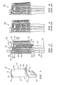
- FIG. 5 shows an inventive core 200 extending from an inboard end 202 to a tip end 204.
- Extending from the inboard end 202 are four trunks 206, 208, 210, and 212.
- the lead trunk 206 extends to a spanwise passageway portion 214 having an outboard end 216.
- the passageway portion 214 is connected to a cavity-forming portion 218 by a number of connectors 220 (FIG. 6).
- the portion 218 has a terminal inboard end 222 and an outboard end 224.
- the trunk 208 extends to a spanwise passageway portion 230 having an outboard end junction 232 with the upstream/leading end of a flag portion 234.
- the flag portion 234 extends to a terminal downstream/trailing end 236.
- the trunk 210 extends to a spanwise up-pass passageway portion 240 having a distal/outboard end joining an outboard end of a spanwise down-pass portion 242.
- the down-pass portion 242 has an inboard end joining an inboard end of a spanwise second up-pass portion 244.
- the up-pass portion 244 extends to a terminal end 246 inboard of an inboard edge 248 of the flag 234.
- the final/trailing trunk 212 extends to a spanwise passageway portion 260.
- the portion 260 extends to an outboard terminal end 262 spaced apart from the flag inboard edge 248.
- a core portion 270 extends downstream from a trailing extremity 272 of the core portion 260 to a trailing edge 274.
- the core portion 270 has an inboard edge 276 and an outboard edge 278.
- the outboard edge 278 is spaced apart from the inboard edge 248 of the flag portion 234.
- the portion 270 may have multiple arrays of apertures for casting posts in a discharge/outlet slot of the airfoil.
- a tip pocket portion 280 is joined to the remainder of the core by one or more connectors 282.
- the trunks and their associated passageway portions may be unitarily molded of a ceramic as a single piece.
- the tip pocket portion may be a portion of the same piece or may be separately molded and secured thereto (e.g., with the connectors 282 acting as mounting studs).
- the core portion 270 may be formed in the same ceramic molding or may be separately formed.
- the portion 270 may be formed from a refractory metal sheet secured in a slot along the trailing edge of the passageway portion 260.
- a terminal portion of the flag 234 may be formed from a refractory metal.
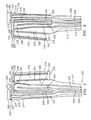
- FIGS. 7 and 8 show further details of the blade cast by the core 200.
- these include a leading edge impingement cavity 310 cast by the core portion 218.
- Drilled or cast outlets 312 may extend to the airfoil pressure or suction side surfaces.
- the cavity 310 has terminal inboard and outboard ends 316 and 318.
- a supply passageway 320 connected to the cavity 310 by impingement ports 322.
- the supply passageway 320 is fed by a dedicated leading trunk 323 cast by the trunk 206.
- the flag passageway 324 is shown in FIG. 7 and its spanwise flagpole/feed passageway 326 are also shown in FIG. 8.
- the flagpole passageway 326 extends from a dedicated trunk 327 cast by the core trunk 208 and is positioned immediately downstream of the passageway 320.
- the exemplary flag passageway 324 has a streamwise length L which is a majority of the local streamwise length of the airfoil (e.g., measured along the airfoil mean).
- the exemplary flag passageway 324 has a width W which is less than the length (e.g., 10-20% of L).
- the flag passageway 324 has inboard and outboard sides 330 and 332 and pressure and suction sides adjacent the respective pressure and suction sides of the airfoil.
- the flag passageway 324 has one or more outlets 334 adjacent or exactly along the trailing edge.
- Downstream of the flagpole passageway 326 is a circuitous passageway formed by an up-pass 340, a down-pass 342, and an up-pass 344 (respectively cast by core portions 240, 242, and 244).
- the up-pass 340 is fed by a dedicated trunk 345 (cast by the core trunk 210) to, in turn, feed the down-pass 342 and up-pass 344 in a partially counterflow arrangement relative to the airfoil streamwise direction.
- the circuit has an end or terminus 350 adjacent a junction 352 of the flag passageway 324 and flagpole passageway 326.
- a trailing feed passageway 360 (cast by the passageway portion 260) extends spanwise from a dedicated trunk 361 (cast by the core trunk 212) to an upward/distal end 362.
- a trailing edge discharge slot 370 (cast by the core portion 270) extends downstream from the passageway 360.
- the slot 370 has inboard and outboard ends 372 and 374 and an array of outlets 376.
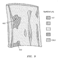
- the passageway arrangement of the blade 300 may have one or more of several advantages. It may be desirable to minimize heating of cooling air before it reaches the flag passageway. Minimizing heating may involve several considerations. One consideration is the position of the flagpole passageway relative to aerodynamically heated regions of the pressure and suction side surfaces 34 and 36. FIG. 9 shows a computed aerodynamic heating of a suction side surface. The exact heat distribution will depend upon airfoil shape and operational parameters. However, with these parameters fixed, and subject to other manufacturing and performance constraints, a routing of the flagpole passageway may be chosen to be aligned with relatively low temperature regions 400 and 402 while avoiding higher adjacent higher temperature regions.
- the foregoing principles may be implemented in the reengineering of a blade, its associated engine, or any intermediate. Such a reengineered blade may, in turn, be used either in a new engine or in a remanufacture/retrofit situation.
- a basic reengineering of a blade, alone, would preserve the external profile of the root, platform, and airfoil. Extensive reengineering might change airfoil shape responsive to the available cooling afforded by the flag passageway.
Landscapes
- Engineering & Computer Science (AREA)
- Mechanical Engineering (AREA)
- General Engineering & Computer Science (AREA)
- Turbine Rotor Nozzle Sealing (AREA)
Abstract

Description
- The invention relates to gas turbine engines. More particularly, the invention relates to cooled gas turbine engine blades.
- Heat management is an important consideration in the engineering and manufacture of turbine engine blades. Blades are commonly formed with a cooling passageway network. A typical network receives cooling air through the blade platform. The cooling air is passed through convoluted paths through the airfoil, with at least a portion exiting the blade through apertures in the airfoil. These apertures may include holes (e.g., "film holes") distributed along the pressure and suction side surfaces of the airfoil and holes at junctions of those surfaces at leading and trailing edges. Additional apertures may be located at the blade tip. In common manufacturing techniques, a principal portion of the blade is formed by a casting and machining process. During the casting process a sacrificial core is utilized to form at least main portions of the cooling passageway network.
- In turbine engine blades (especially high pressure turbine (HPT) section blades), thermal fatigue of tip region of a blade airfoil is one area of particular concern.
US Patent No. 6,824,359 discloses cooling air outlet passageways fanned along a trailing tip region of the airfoil. US Pregrant Publication No. 2004/0146401 discloses direction of air through a relief in a wall of a tip pocket to cool a trailing tip portion. US PatentNo. 6,974,308 discloses use of a tip flag passageway to deliver a high volume of cooling air to a trailing tip portion. - One aspect of the invention involves a turbine engine blade having an attachment root, a platform outboard of the attachment root, and an airfoil extending from the platform. The airfoil has pressure and suction sides extending between leading and trailing edges. An internal cooling passageway network includes at least one inlet in the root and a plurality of outlets along the airfoil. The passageway network includes a leading spanwise cavity fed by a first trunk. A streamwise cavity is inboard of a tip of the airfoil. A spanwise feed cavity feeds the streamwise cavity absent down-pass. A second trunk feeds the spanwise feed cavity.
- A second aspect of the invention involves a method for cooling a turbine engine blade airfoil comprising: passing a plurality of trunk airflows into the airfoil; and passing an airflow of said trunk airflows into a streamwise cavity inboard of the tip absent down-pass and with 0-20% diversion.
- A third aspect of the invention involves a casting core for forming a turbine engine blade and comprising: a root end and a tip end; a pressure side and a suction side; a leading spanwise portion; a first trunk portion; means linking the first trunk portion and the leading spanwise portion; a streamwise elongate portion inboard of the tip; a second trunk portion; and means noncircuitiously linking the second trunk portion and the streamwise elongate portion.
- A fourth aspect of the invention involves a method for engineering a turbine engine blade comprising: determining an aerodynamic heating distribution; and positioning a feed passageway for a streamwise tip passageway to as to avoid an undesired heating of cooling air delivered to the tip passageway through the feed passageway.
- A fifth aspect of the invention involves a method for remanufacturing a turbine engine or reengineering a configuration of said turbine engine, the remanufacturing or reengineering being from a baseline configuration to a final configuration and comprising: reconfiguring a cooling passageway system of a blade from a baseline configuration to a final configuration so as to at least one of: reduce an operational air temperature increase at a downstream end of a spanwise feed passageway relative to a blade inlet temperature, the spanwise feed passageway feeding a streamwise elongate tip end passageway; and provide a dedicated passageway trunk to feed a final configuration spanwise feed passageway feeding a final configuration streamwise elongate tip end passageway whereas the blade baseline configuration has one fewer passageway trunks and a baseline configuration spanwise feed passageway feeding a baseline configuration streamwise elongate tip end passageway is fed by a trunk shared with another spanwise passageway.
- Other, preferred features of the invention will be apparent from the claims.
- The details of one or more embodiments of the invention are set forth in the accompanying drawings and the description below. Other features and advantages of the invention will be apparent from the description and drawings, and from the claims.
-
- FIG. 1 is a view of a gas turbine engine blade.
- FIG. 2 is a view of a first prior art casting core for forming blade cooling passageways.
- FIG. 3 is a view of a second prior art casting core for forming blade cooling passageways.
- FIG. 4 is a view of a third prior art casting core for forming blade cooling passageways.
- FIG. 5 is a first side view of a core according to principles of the invention.
- FIG. 6 is a second side view of the core of FIG. 5.
- FIG. 7 is a view of an airfoil of a blade cast using the core of FIG. 5.
- FIG. 8 is a cross-sectional view of the airfoil of FIG. 7, taken along line 8-8.
- FIG. 9 is a diagram of aerodynamic surface heating for the airfoil of FIG. 7.
- Like reference numbers and designations in the various drawings indicate like elements.
- FIG. 1 shows a blade 20 (e.g., an HPT blade) having an
airfoil 22 extending along a span from aninboard end 24 to anoutboard tip 26. The blade has leading and trailingedges suction sides tip compartment 38 may be formed recessed below a remaining portion of thetip 26. - A
platform 40 is formed at theinboard end 24 of the airfoil and locally forms an inboard extreme.of a core flowpath through the engine. A convoluted so-called "fir tree"attachment root 42 depends from the underside of theplatform 40 for attaching the blade to a separate disk. One ormore ports 44 may be formed in an inboard end of theroot 42 for admitting cooling air to the blade. The cooling air may pass through a passageway system and exit through a number of outlets along the airfoil. As so far described, theblade 40 may be representative of many existing or yet-developed blade configurations. Additionally, the principles discussed below may be applied to other blade configurations. - FIG. 2 shows an exemplary
prior art core 60 used to cast major portions of a passageway system of a prior art blade. Theexemplary core 60 may be formed of one or more molded ceramic pieces assembled to each other or to additional components such as refractory metal cores. For ease of reference, core directions are identified relative to associated directions of the resulting blade cast using the core. Similarly, core portions may be identified with names corresponding to associated passageway portions formed when those core portions are removed from a casting. Additional passageway portions may be drilled or otherwise machined. - The
core 60 extends from aninboard end 62 to an outboard/tip end 64. Threetrunks inboard end 62. The trunks extend within the root of the resulting blade and form associated passageway trunks. The trunks may be joined at the inboard end (typically in a portion of the core that is embedded in a casting shell and falls outside the blade root). The leadingtrunk 66 joins/feeds a first spanwisefeed passageway portion 80 extending to atip end 82. Thefeed passageway portion 80 is connected to a leading edge impingement chamber/cavity portion 84. The cavity cast by theportion 84 may be impingement fed by airflow from the feed passageway cast by theportion 80, the air passing through a series of apertures cast by connectingposts 86. The cavity may then cool a leading edge portion of the airfoil via drilled or cast outlet holes. - The
second trunk 68 joins aspanwise passageway portion 90 having a distal end merged with a proximal end of streamwise extendingportion 92. In the vernacular, theportion 92 is a tip flag portion and theportion 90 is a flagpole portion. Theflag portion 92 extends downstream toward the trailing edge adjacent the tip end and has a distal/downstream end 94. The outboard end of theportion 90 also joins a spanwise down-pass portion 96 thereahead. At its inboard end, the down-pass portion 96 joins an up-pass portion 98 extending to anoutboard end 100. In operation, air flows outboard through the second trunk passageway and the flagpole/feed passageway formed by theportion 90. At the downstream end of the flagpole passageway, a major portion of that air flows into the flag passageway ultimately exiting at outlets near the downstream end thereof. Another air portion returns back inboard through the down-pass and then proceeds outboard through the up-pass. Aconnector 102 may have a relatively small cross-sectional area and may serve a structural role in providing core rigidity. A connecting passageway initially formed by aconnector 102 may be blocked (e.g., with a ball braze) to prevent air bypass directly from the trunk to the up-pass. - A
core portion 120 may serve to cast the tip pocket. To hold thisportion 120, connectingportions 122 join theportion 120 to theends flag 92. Small amounts of air may pass through holes formed by the connectingportions 122 to feed the tip pocket. - The
third trunk 70 joins a trailing edgefeed passageway portion 130. Along its trailing extremity, theportion 130 is connected to a discharge slot-formingportion 132. Theportion 132 may be unitarily formed with theportion 130 or may be a separate piece (e.g., refractory metal core) secured thereto. Outboard ends 140 and 142 of theportions inboard edge 144 of theflag 92. A gap between these portions may leave a wall (e.g., continuous with a wall formed between thetrunks passageway portions 90 and 130) in the cast blade. The wall isolates the air feeding the flag from heating that might otherwise occur if the flag were fed via the trailing passageway. - FIG. 3 shows an
alternate core 160 for forming a blade wherein the flag is fed via a leading trunk and from a spanwise flagpole passageway that also impingement feeds a leading edge cavity. - FIG. 4 shows an alternate core wherein the leading edge cavity is both impingement fed from the flagpole passageway and fed from the leading trunk.
- FIG. 5 shows an
inventive core 200 extending from aninboard end 202 to atip end 204. Extending from theinboard end 202 are fourtrunks lead trunk 206 extends to aspanwise passageway portion 214 having anoutboard end 216. Along its leading face, thepassageway portion 214 is connected to a cavity-formingportion 218 by a number of connectors 220 (FIG. 6). Theportion 218 has a terminalinboard end 222 and anoutboard end 224. - The
trunk 208 extends to aspanwise passageway portion 230 having anoutboard end junction 232 with the upstream/leading end of aflag portion 234. Theflag portion 234 extends to a terminal downstream/trailingend 236. - The
trunk 210 extends to a spanwise up-pass passageway portion 240 having a distal/outboard end joining an outboard end of a spanwise down-pass portion 242. The down-pass portion 242 has an inboard end joining an inboard end of a spanwise second up-pass portion 244. The up-pass portion 244 extends to aterminal end 246 inboard of aninboard edge 248 of theflag 234. - The final/trailing
trunk 212 extends to aspanwise passageway portion 260. Theportion 260 extends to an outboardterminal end 262 spaced apart from the flaginboard edge 248. Acore portion 270 extends downstream from a trailingextremity 272 of thecore portion 260 to a trailingedge 274. Thecore portion 270 has aninboard edge 276 and anoutboard edge 278. Theoutboard edge 278 is spaced apart from theinboard edge 248 of theflag portion 234. Theportion 270 may have multiple arrays of apertures for casting posts in a discharge/outlet slot of the airfoil. - A
tip pocket portion 280 is joined to the remainder of the core by one ormore connectors 282. - In an
exemplary core 200, the trunks and their associated passageway portions may be unitarily molded of a ceramic as a single piece. The tip pocket portion may be a portion of the same piece or may be separately molded and secured thereto (e.g., with theconnectors 282 acting as mounting studs). Thecore portion 270 may be formed in the same ceramic molding or may be separately formed. For example, theportion 270 may be formed from a refractory metal sheet secured in a slot along the trailing edge of thepassageway portion 260. Similarly, a terminal portion of theflag 234 may be formed from a refractory metal. - FIGS. 7 and 8 show further details of the blade cast by the
core 200. Along the majority of the airfoil span, there are a series of spanwise elongate passageways or portions thereof. In the exemplary airfoil, these include a leadingedge impingement cavity 310 cast by thecore portion 218. Drilled or castoutlets 312 may extend to the airfoil pressure or suction side surfaces. Thecavity 310 has terminal inboard and outboard ends 316 and 318. - Next downstream is a
supply passageway 320 connected to thecavity 310 byimpingement ports 322. Thesupply passageway 320 is fed by a dedicated leading trunk 323 cast by thetrunk 206. - The
flag passageway 324 is shown in FIG. 7 and its spanwise flagpole/feed passageway 326 are also shown in FIG. 8. Theflagpole passageway 326 extends from adedicated trunk 327 cast by thecore trunk 208 and is positioned immediately downstream of thepassageway 320. Theexemplary flag passageway 324 has a streamwise length L which is a majority of the local streamwise length of the airfoil (e.g., measured along the airfoil mean). Theexemplary flag passageway 324 has a width W which is less than the length (e.g., 10-20% of L). Theflag passageway 324 has inboard andoutboard sides flag passageway 324 has one ormore outlets 334 adjacent or exactly along the trailing edge. - Downstream of the
flagpole passageway 326 is a circuitous passageway formed by an up-pass 340, a down-pass 342, and an up-pass 344 (respectively cast bycore portions pass 340 is fed by a dedicated trunk 345 (cast by the core trunk 210) to, in turn, feed the down-pass 342 and up-pass 344 in a partially counterflow arrangement relative to the airfoil streamwise direction. The circuit has an end or terminus 350 adjacent ajunction 352 of theflag passageway 324 andflagpole passageway 326. Along the circuit, there may be outlet holes 354 (FIG. 8) (e.g., drilled or cast) to the pressure and/or suction side surfaces. A trailing feed passageway 360 (cast by the passageway portion 260) extends spanwise from a dedicated trunk 361 (cast by the core trunk 212) to an upward/distal end 362. A trailing edge discharge slot 370 (cast by the core portion 270) extends downstream from thepassageway 360. Theslot 370 has inboard and outboard ends 372 and 374 and an array ofoutlets 376. - Relative to the prior art airfoils cast by the cores of FIGS. 2-4, the passageway arrangement of the
blade 300 may have one or more of several advantages. It may be desirable to minimize heating of cooling air before it reaches the flag passageway. Minimizing heating may involve several considerations. One consideration is the position of the flagpole passageway relative to aerodynamically heated regions of the pressure and suction side surfaces 34 and 36. FIG. 9 shows a computed aerodynamic heating of a suction side surface. The exact heat distribution will depend upon airfoil shape and operational parameters. However, with these parameters fixed, and subject to other manufacturing and performance constraints, a routing of the flagpole passageway may be chosen to be aligned with relativelylow temperature regions - Other considerations regarding the temperature and amount of air reaching the flag tip passageway involve the interplay of other passageways. If the flagpole passageway or its associated trunk directly feed another passageway, factors influencing the diversion of airflow to such other passageway may affect cooling along the flag tip passageway. For example, in the airfoil cast by the FIG. 3
core 160, a leading edge impingement cavity is directly fed by the flagpole passageway. Various aerodynamic considerations (including blade rotational speed, altitude, and fueling) may influence the amount of air discharged from the impingement cavity through its outlet holes. This, in turn, affects the airflow available for the flag passageway. This effect may also be observed in an airfoil cast from the FIG. 4core 180 wherein the leading edge impingement cavity is additionally fed by a leading trunk shared with the flagpole passageway. Similar effects may be observed in an airfoil cast by thecore 60 of FIG. 2 wherein the flagpole passageway and its associated trunk feed a mid-foil down-pass/up-pass circuit. - The foregoing principles may be implemented in the reengineering of a blade, its associated engine, or any intermediate. Such a reengineered blade may, in turn, be used either in a new engine or in a remanufacture/retrofit situation. A basic reengineering of a blade, alone, would preserve the external profile of the root, platform, and airfoil. Extensive reengineering might change airfoil shape responsive to the available cooling afforded by the flag passageway.
- One or more embodiments of the present invention have been described. Nevertheless, it will be understood that various modifications may be made without departing from the scope of the invention. Accordingly, other embodiments are within the scope of the following claims.
Claims (24)
- A turbine engine blade (20) comprising:an attachment root (42);a platform (40) outboard of the attachment root;an airfoil (22) extending from the platform and having:leading (30) and trailing (32) edges;pressure (34) and suction (36) sides extending between the leading and trailing edges; anda tip (26); andan internal cooling passageway network having:wherein:at least one inlet (44) in the attachment root (42); anda plurality of outlets (334, 376) along the airfoil,the cooling passageway network comprises:a leading spanwise cavity (310);a first trunk (323) feeding the leading spanwise cavity;a streamwise cavity (324) inboard of the tip (26);a spanwise feed cavity (326) feeding the streamwise cavity (324) absent down-pass; anda second trunk (327) feeding the spanwise feed cavity (326).
- The blade of claim 1 wherein:the leading spanwise cavity (310) is an impingement cavity; anda spanwise impingement feed cavity (320) extends from the first trunk (323) to impingement feed the leading spanwise cavity (310).
- The blade of claim 1 or 2 wherein:the streamwise cavity (324) has a streamwise length (L) at least 60% of a local streamwise length of the airfoil.
- The blade of any preceding claim further comprising:a trailing spanwise cavity (360); anda third trunk (361) feeding the trailing spanwise cavity (360).
- The blade of any preceding claim further comprising:a mid-body passageway comprising:a first spanwise up-pass (340);a spanwise down-pass (342) fed by the first spanwise up-pass (340); anda second spanwise up-pass (344) fed by the spanwise down-pass (342);a third trunk (345) feeding the first spanwise up-pass (340);a trailing spanwise cavity (360); anda fourth trunk (361) feeding the trailing spanwise cavity (360).
- The blade of any preceding claim formed as a single casting.
- The blade of any preceding claim further comprising:a tip cavity (38) partially fed by the first trunk (323) and partially fed by the second trunk (327).
- A method for cooling a turbine engine blade (20) airfoil (22) comprising:passing a plurality of trunk airflows into the airfoil; andpassing an airflow of said trunk airflows into a streamwise cavity (324) inboard of the tip (26) absent down-pass and with 0-20% diversion.
- The method of claim 8 wherein:the passing of the airflow comprises passing from a trunk cavity (327) through a spanwise feed cavity (326) and into a leading end of the streamwise cavity (324).
- The method of claim 9 wherein:the passing of the airflow comprises discharging from an outlet (334) along the trailing edge (32).
- The method of claim 8, 9 or 10 further comprising:passing another airflow of said trunk airflows into a leading spanwise cavity (310).
- The method of any of claims 8 to 11 further comprising:passing another airflow of said trunk airflows into a trailing spanwise cavity (360).
- The method of claim 12 wherein:the passing of said another airflow comprises discharging from a trailing edge slot (370).
- The method of any of claims 8 to 13 further comprising:passing a portion of said diversion into an open tip cavity (38).
- The method of claim 14 further comprising:passing a portion of another of the trunk airflows into the open tip cavity (38).
- A casting core (200) for forming a turbine engine blade (20) and comprising:a root end (202) and a tip end (204);a pressure side and a suction side;a leading spanwise portion (218);a first trunk portion (206);means (214, 220) linking the first trunk portion (206) and the leading spanwise portion (218);a streamwise elongate portion (234) inboard of the tip (204);a second trunk portion (208); andmeans (230, 232) noncircuitiously linking the second trunk portion (208) and the streamwise elongate portion (234).
- The casting core of claim 16 further comprising:a trailing spanwise portion (260);means (270) for forming a discharge slot (370) either unitarily formed with or secured to the trailing spanwise portion (260);a third trunk portion (212) coupled to the trailing spanwise portion (260).
- The casting core of claim 16 or 17 further comprising:a circuitous intermediate portion including three spanwise portions (240, 242, 244);a third trunk portion (210) coupled to the intermediate portion;a trailing spanwise portion (260);means (270) for forming a discharge slot (370) either unitarily formed with or secured to the trailing spanwise portion (260);a fourth trunk portion (212) coupled to the trailing spanwise portion.
- A method for engineering a turbine engine blade comprising:determining an aerodynamic heating distribution; andpositioning a feed passageway (326) for a streamwise tip passageway (324) to as to avoid an undesired heating of cooling air delivered to the tip passageway through the feed passageway.
- The method of claim 19 further comprising:configuring the feed passageway to provide 0-20% diversion of an inlet airflow providing the cooling air delivered to the tip passageway (324).
- The method of claim 19 or 20 being a reengineering from a baseline configuration to a reengineered configuration and wherein:the reengineered configuration adds at least one trunk relative to the baseline configuration; andthe baseline configuration includes a streamwise tip passageway fed with at least one of:a greater than 10% diversion from an associated trunk; anda circuitous up-pass/down-pass/up-pass combination.
- The method of claim 19 being a reengineering from a baseline configuration to a reengineered configuration and wherein:the reengineered configuration adds at least one trunk relative to the baseline configurationthe reengineered configuration provides 0-10% diversion of an inlet airflow providing the cooling air delivered to the tip passageway; andthe baseline configuration includes a streamwise tip passageway fed with at least one of:a greater than 20% diversion from an associated trunk; anda circuitous up-pass/down-pass/up-pass combination.
- A method for remanufacturing a turbine engine or reengineering a configuration of said turbine engine, the remanufacturing or reengineering being from a baseline configuration to a final configuration and comprising:reconfiguring a cooling passageway system of a blade (20) from a baseline configuration to a final configuration so as to at least one of:reduce an operational air temperature increase at a downstream end of a spanwise feed passageway relative to a blade inlet temperature, the spanwise feed passageway feeding a streamwise elongate tip end passageway (324); andprovide a dedicated passageway trunk (327) to feed a final configuration spanwise feed passageway (326) feeding a final configuration streamwise elongate tip end passageway (324) whereas the blade baseline configuration has one fewer passageway trunks and a baseline configuration spanwise feed passageway feeding a baseline configuration streamwise elongate tip end passageway is fed by a trunk shared with another spanwise passageway.
- The method of claim 23 wherein:reconfiguring includes said provision of said dedicated passageway trunk by adding at least one trunk to a trunk number of the baseline configuration.
Applications Claiming Priority (1)
| Application Number | Priority Date | Filing Date | Title |
|---|---|---|---|
| US11/317,394 US7413403B2 (en) | 2005-12-22 | 2005-12-22 | Turbine blade tip cooling |
Publications (3)
| Publication Number | Publication Date |
|---|---|
| EP1801351A2 true EP1801351A2 (en) | 2007-06-27 |
| EP1801351A3 EP1801351A3 (en) | 2010-11-24 |
| EP1801351B1 EP1801351B1 (en) | 2016-03-02 |
Family
ID=37888097
Family Applications (1)
| Application Number | Title | Priority Date | Filing Date |
|---|---|---|---|
| EP06256420.8A Active EP1801351B1 (en) | 2005-12-22 | 2006-12-18 | Turbine blade tip cooling |
Country Status (7)
| Country | Link |
|---|---|
| US (1) | US7413403B2 (en) |
| EP (1) | EP1801351B1 (en) |
| JP (1) | JP2007170379A (en) |
| KR (1) | KR20070066843A (en) |
| CN (1) | CN1987054A (en) |
| SG (1) | SG133467A1 (en) |
| TW (1) | TW200724775A (en) |
Cited By (3)
| Publication number | Priority date | Publication date | Assignee | Title |
|---|---|---|---|---|
| EP2119872A2 (en) | 2008-05-14 | 2009-11-18 | United Technologies Corporation | Turbine blade internal cooling configuration |
| EP2119873A3 (en) * | 2008-05-14 | 2013-11-13 | United Technologies Corporation | Airfoil with triangular serpentine cooling channels |
| EP2540965B2 (en) † | 2011-06-30 | 2022-02-16 | Raytheon Technologies Corporation | Manufacturing method for a ceramic fiber reinforced ceramic composite component with internal three-dimensionally woven platform and corresponding component |
Families Citing this family (45)
| Publication number | Priority date | Publication date | Assignee | Title |
|---|---|---|---|---|
| US7674093B2 (en) * | 2006-12-19 | 2010-03-09 | General Electric Company | Cluster bridged casting core |
| US7866370B2 (en) * | 2007-01-30 | 2011-01-11 | United Technologies Corporation | Blades, casting cores, and methods |
| US8157527B2 (en) | 2008-07-03 | 2012-04-17 | United Technologies Corporation | Airfoil with tapered radial cooling passage |
| US8572844B2 (en) | 2008-08-29 | 2013-11-05 | United Technologies Corporation | Airfoil with leading edge cooling passage |
| US8303252B2 (en) | 2008-10-16 | 2012-11-06 | United Technologies Corporation | Airfoil with cooling passage providing variable heat transfer rate |
| US8100165B2 (en) * | 2008-11-17 | 2012-01-24 | United Technologies Corporation | Investment casting cores and methods |
| US8171978B2 (en) | 2008-11-21 | 2012-05-08 | United Technologies Corporation | Castings, casting cores, and methods |
| US8113780B2 (en) * | 2008-11-21 | 2012-02-14 | United Technologies Corporation | Castings, casting cores, and methods |
| US8109725B2 (en) | 2008-12-15 | 2012-02-07 | United Technologies Corporation | Airfoil with wrapped leading edge cooling passage |
| GB2468669C (en) * | 2009-03-17 | 2013-11-13 | Rolls Royce Plc | A flow discharge device |
| US8052378B2 (en) * | 2009-03-18 | 2011-11-08 | General Electric Company | Film-cooling augmentation device and turbine airfoil incorporating the same |
| US20100239409A1 (en) * | 2009-03-18 | 2010-09-23 | General Electric Company | Method of Using and Reconstructing a Film-Cooling Augmentation Device for a Turbine Airfoil |
| US8118553B2 (en) * | 2009-03-20 | 2012-02-21 | Siemens Energy, Inc. | Turbine airfoil cooling system with dual serpentine cooling chambers |
| EP2243574A1 (en) * | 2009-04-20 | 2010-10-27 | Siemens Aktiengesellschaft | Casting device for creating a turbine rotor blade of a gas turbine and turbine rotor blade |
| US8764379B2 (en) * | 2010-02-25 | 2014-07-01 | General Electric Company | Turbine blade with shielded tip coolant supply passageway |
| US8876484B2 (en) | 2011-08-05 | 2014-11-04 | Hamilton Sundstrand Corporation | Turbine blade pocket pin stress relief |
| US9200523B2 (en) | 2012-03-14 | 2015-12-01 | Honeywell International Inc. | Turbine blade tip cooling |
| US9429027B2 (en) | 2012-04-05 | 2016-08-30 | United Technologies Corporation | Turbine airfoil tip shelf and squealer pocket cooling |
| US9279331B2 (en) | 2012-04-23 | 2016-03-08 | United Technologies Corporation | Gas turbine engine airfoil with dirt purge feature and core for making same |
| US20130330184A1 (en) * | 2012-06-08 | 2013-12-12 | General Electric Company | Aerodynamic element of turbine engine |
| US10408066B2 (en) | 2012-08-15 | 2019-09-10 | United Technologies Corporation | Suction side turbine blade tip cooling |
| US9115590B2 (en) | 2012-09-26 | 2015-08-25 | United Technologies Corporation | Gas turbine engine airfoil cooling circuit |
| US9995148B2 (en) | 2012-10-04 | 2018-06-12 | General Electric Company | Method and apparatus for cooling gas turbine and rotor blades |
| US8920123B2 (en) | 2012-12-14 | 2014-12-30 | Siemens Aktiengesellschaft | Turbine blade with integrated serpentine and axial tip cooling circuits |
| WO2014164888A1 (en) * | 2013-03-11 | 2014-10-09 | United Technologies Corporation | Low pressure loss cooled blade |
| US20160222794A1 (en) * | 2013-09-09 | 2016-08-04 | United Technologies Corporation | Incidence tolerant engine component |
| US10041374B2 (en) * | 2014-04-04 | 2018-08-07 | United Technologies Corporation | Gas turbine engine component with platform cooling circuit |
| FR3021697B1 (en) * | 2014-05-28 | 2021-09-17 | Snecma | OPTIMIZED COOLING TURBINE BLADE |
| CN106660125B (en) * | 2014-05-30 | 2023-03-17 | 诺沃皮尼奥内技术股份有限公司 | Method of manufacturing a turbomachine component, turbomachine component and turbomachine |
| US9714583B2 (en) * | 2014-08-21 | 2017-07-25 | Honeywell International Inc. | Fan containment cases for fan casings in gas turbine engines, fan blade containment systems, and methods for producing the same |
| US9835087B2 (en) | 2014-09-03 | 2017-12-05 | General Electric Company | Turbine bucket |
| JP2018512535A (en) | 2015-03-17 | 2018-05-17 | シーメンス エナジー インコーポレイテッド | Turbine blade with unconstrained flow diverting guide structure |
| FR3034128B1 (en) * | 2015-03-23 | 2017-04-14 | Snecma | CERAMIC CORE FOR MULTI-CAVITY TURBINE BLADE |
| FR3037829B1 (en) * | 2015-06-29 | 2017-07-21 | Snecma | CORE FOR MOLDING A DAWN WITH OVERLAPPED CAVITIES AND COMPRISING A DEDUSISHING HOLE THROUGH A CAVITY PARTLY |
| US10563521B2 (en) | 2016-12-05 | 2020-02-18 | United Technologies Corporation | Aft flowing serpentine cavities and cores for airfoils of gas turbine engines |
| US10815800B2 (en) | 2016-12-05 | 2020-10-27 | Raytheon Technologies Corporation | Radially diffused tip flag |
| US10465529B2 (en) | 2016-12-05 | 2019-11-05 | United Technologies Corporation | Leading edge hybrid cavities and cores for airfoils of gas turbine engine |
| US10989056B2 (en) | 2016-12-05 | 2021-04-27 | Raytheon Technologies Corporation | Integrated squealer pocket tip and tip shelf with hybrid and tip flag core |
| US20190003316A1 (en) * | 2017-06-29 | 2019-01-03 | United Technologies Corporation | Helical skin cooling passages for turbine airfoils |
| US11566527B2 (en) * | 2018-12-18 | 2023-01-31 | General Electric Company | Turbine engine airfoil and method of cooling |
| US11021966B2 (en) * | 2019-04-24 | 2021-06-01 | Raytheon Technologies Corporation | Vane core assemblies and methods |
| CN111677557B (en) * | 2020-06-08 | 2021-10-26 | 清华大学 | Turbine guide blade and turbo machine with same |
| US12006836B2 (en) | 2021-07-02 | 2024-06-11 | Rtx Corporation | Cooling arrangement for gas turbine engine component |
| US11913353B2 (en) | 2021-08-06 | 2024-02-27 | Rtx Corporation | Airfoil tip arrangement for gas turbine engine |
| US20260117660A1 (en) * | 2024-10-28 | 2026-04-30 | Doosan Enerbility Co., Ltd. | Airfoil, turbine blade including the airfoil, and gas turbine including the turbine blade |
Family Cites Families (20)
| Publication number | Priority date | Publication date | Assignee | Title |
|---|---|---|---|---|
| JPS59231102A (en) * | 1983-06-15 | 1984-12-25 | Toshiba Corp | Gas turbine blade |
| JPH06102963B2 (en) * | 1983-12-22 | 1994-12-14 | 株式会社東芝 | Gas turbine air cooling blade |
| US4767268A (en) * | 1987-08-06 | 1988-08-30 | United Technologies Corporation | Triple pass cooled airfoil |
| US4753575A (en) * | 1987-08-06 | 1988-06-28 | United Technologies Corporation | Airfoil with nested cooling channels |
| JPH06137102A (en) * | 1992-10-26 | 1994-05-17 | Mitsubishi Heavy Ind Ltd | Hollow moving blade of gas turbine |
| WO1994012768A2 (en) * | 1992-11-24 | 1994-06-09 | United Technologies Corporation | Coolable airfoil structure |
| US5403159A (en) * | 1992-11-30 | 1995-04-04 | United Technoligies Corporation | Coolable airfoil structure |
| US5603606A (en) * | 1994-11-14 | 1997-02-18 | Solar Turbines Incorporated | Turbine cooling system |
| EP0954679B1 (en) * | 1996-06-28 | 2003-01-22 | United Technologies Corporation | Coolable airfoil for a gas turbine engine |
| US5931638A (en) * | 1997-08-07 | 1999-08-03 | United Technologies Corporation | Turbomachinery airfoil with optimized heat transfer |
| US5902093A (en) * | 1997-08-22 | 1999-05-11 | General Electric Company | Crack arresting rotor blade |
| JPH11241602A (en) * | 1998-02-26 | 1999-09-07 | Toshiba Corp | Gas turbine blades |
| US6168381B1 (en) * | 1999-06-29 | 2001-01-02 | General Electric Company | Airfoil isolated leading edge cooling |
| US6595748B2 (en) * | 2001-08-02 | 2003-07-22 | General Electric Company | Trichannel airfoil leading edge cooling |
| US6637500B2 (en) * | 2001-10-24 | 2003-10-28 | United Technologies Corporation | Cores for use in precision investment casting |
| US6974308B2 (en) * | 2001-11-14 | 2005-12-13 | Honeywell International, Inc. | High effectiveness cooled turbine vane or blade |
| US7059834B2 (en) * | 2003-01-24 | 2006-06-13 | United Technologies Corporation | Turbine blade |
| US6824359B2 (en) * | 2003-01-31 | 2004-11-30 | United Technologies Corporation | Turbine blade |
| US7104757B2 (en) * | 2003-07-29 | 2006-09-12 | Siemens Aktiengesellschaft | Cooled turbine blade |
| US7632071B2 (en) * | 2005-12-15 | 2009-12-15 | United Technologies Corporation | Cooled turbine blade |
-
2005
- 2005-12-22 US US11/317,394 patent/US7413403B2/en active Active
-
2006
- 2006-08-07 SG SG200605356-5A patent/SG133467A1/en unknown
- 2006-08-09 TW TW095129217A patent/TW200724775A/en unknown
- 2006-09-08 KR KR1020060086548A patent/KR20070066843A/en not_active Ceased
- 2006-12-12 JP JP2006333937A patent/JP2007170379A/en active Pending
- 2006-12-18 EP EP06256420.8A patent/EP1801351B1/en active Active
- 2006-12-22 CN CNA2006101686678A patent/CN1987054A/en active Pending
Cited By (4)
| Publication number | Priority date | Publication date | Assignee | Title |
|---|---|---|---|---|
| EP2119872A2 (en) | 2008-05-14 | 2009-11-18 | United Technologies Corporation | Turbine blade internal cooling configuration |
| EP2119872A3 (en) * | 2008-05-14 | 2012-08-08 | United Technologies Corporation | Turbine blade internal cooling configuration |
| EP2119873A3 (en) * | 2008-05-14 | 2013-11-13 | United Technologies Corporation | Airfoil with triangular serpentine cooling channels |
| EP2540965B2 (en) † | 2011-06-30 | 2022-02-16 | Raytheon Technologies Corporation | Manufacturing method for a ceramic fiber reinforced ceramic composite component with internal three-dimensionally woven platform and corresponding component |
Also Published As
| Publication number | Publication date |
|---|---|
| TW200724775A (en) | 2007-07-01 |
| CN1987054A (en) | 2007-06-27 |
| EP1801351A3 (en) | 2010-11-24 |
| US7413403B2 (en) | 2008-08-19 |
| JP2007170379A (en) | 2007-07-05 |
| EP1801351B1 (en) | 2016-03-02 |
| SG133467A1 (en) | 2007-07-30 |
| US20070147997A1 (en) | 2007-06-28 |
| KR20070066843A (en) | 2007-06-27 |
Similar Documents
| Publication | Publication Date | Title |
|---|---|---|
| US7413403B2 (en) | Turbine blade tip cooling | |
| EP1952911B1 (en) | Turbine blade, casting core and method | |
| US6186741B1 (en) | Airfoil component having internal cooling and method of cooling | |
| EP1953343B1 (en) | Cooling system for a gas turbine blade and corresponding gas turbine blade | |
| US6824359B2 (en) | Turbine blade | |
| US7625172B2 (en) | Vane platform cooling | |
| US7014424B2 (en) | Turbine element | |
| EP1659264B1 (en) | Airfoil with supplemental cooling channel adjacent leading edge | |
| US7744347B2 (en) | Peripheral microcircuit serpentine cooling for turbine airfoils | |
| US8043060B1 (en) | Turbine blade with trailing edge cooling | |
| EP1923152B1 (en) | Trubine blade casting method | |
| US8613597B1 (en) | Turbine blade with trailing edge cooling | |
| US8317474B1 (en) | Turbine blade with near wall cooling | |
| JP4175669B2 (en) | Cooling channel structure for cooling the trailing edge of gas turbine blades | |
| US7572102B1 (en) | Large tapered air cooled turbine blade | |
| EP3822455B1 (en) | Airfoil with ribs defining shaped cooling channel | |
| CA2513036C (en) | Airfoil cooling passage trailing edge flow restriction | |
| EP4450761A1 (en) | Airfoil element, gas turbine engine, method for manufacturing an airfoil element, method for using an airfoil element, airfoil element and casting core assembly for casting an airfoil element | |
| CA2258206C (en) | Configuration of cooling channels for cooling the trailing edge of gas turbine vanes |
Legal Events
| Date | Code | Title | Description |
|---|---|---|---|
| PUAI | Public reference made under article 153(3) epc to a published international application that has entered the european phase |
Free format text: ORIGINAL CODE: 0009012 |
|
| AK | Designated contracting states |
Kind code of ref document: A2 Designated state(s): AT BE BG CH CY CZ DE DK EE ES FI FR GB GR HU IE IS IT LI LT LU LV MC NL PL PT RO SE SI SK TR |
|
| AX | Request for extension of the european patent |
Extension state: AL BA HR MK YU |
|
| PUAL | Search report despatched |
Free format text: ORIGINAL CODE: 0009013 |
|
| AK | Designated contracting states |
Kind code of ref document: A3 Designated state(s): AT BE BG CH CY CZ DE DK EE ES FI FR GB GR HU IE IS IT LI LT LU LV MC NL PL PT RO SE SI SK TR |
|
| AX | Request for extension of the european patent |
Extension state: AL BA HR MK RS |
|
| 17P | Request for examination filed |
Effective date: 20110523 |
|
| AKX | Designation fees paid |
Designated state(s): DE GB |
|
| 17Q | First examination report despatched |
Effective date: 20131219 |
|
| GRAP | Despatch of communication of intention to grant a patent |
Free format text: ORIGINAL CODE: EPIDOSNIGR1 |
|
| INTG | Intention to grant announced |
Effective date: 20150707 |
|
| GRAS | Grant fee paid |
Free format text: ORIGINAL CODE: EPIDOSNIGR3 |
|
| GRAA | (expected) grant |
Free format text: ORIGINAL CODE: 0009210 |
|
| AK | Designated contracting states |
Kind code of ref document: B1 Designated state(s): DE GB |
|
| REG | Reference to a national code |
Ref country code: GB Ref legal event code: FG4D |
|
| REG | Reference to a national code |
Ref country code: DE Ref legal event code: R081 Ref document number: 602006048068 Country of ref document: DE Owner name: UNITED TECHNOLOGIES CORP. (N.D.GES.D. STAATES , US Free format text: FORMER OWNER: UNITED TECHNOLOGIES CORP. (N.D.GES.D. STAATES DELAWARE), HARTFORD, CONN., US |
|
| REG | Reference to a national code |
Ref country code: DE Ref legal event code: R096 Ref document number: 602006048068 Country of ref document: DE |
|
| RAP2 | Party data changed (patent owner data changed or rights of a patent transferred) |
Owner name: UNITED TECHNOLOGIES CORPORATION |
|
| REG | Reference to a national code |
Ref country code: DE Ref legal event code: R097 Ref document number: 602006048068 Country of ref document: DE |
|
| PLBE | No opposition filed within time limit |
Free format text: ORIGINAL CODE: 0009261 |
|
| STAA | Information on the status of an ep patent application or granted ep patent |
Free format text: STATUS: NO OPPOSITION FILED WITHIN TIME LIMIT |
|
| 26N | No opposition filed |
Effective date: 20161205 |
|
| REG | Reference to a national code |
Ref country code: DE Ref legal event code: R082 Ref document number: 602006048068 Country of ref document: DE Representative=s name: SCHMITT-NILSON SCHRAUD WAIBEL WOHLFROM PATENTA, DE |
|
| REG | Reference to a national code |
Ref country code: DE Ref legal event code: R082 Ref document number: 602006048068 Country of ref document: DE Representative=s name: SCHMITT-NILSON SCHRAUD WAIBEL WOHLFROM PATENTA, DE Ref country code: DE Ref legal event code: R081 Ref document number: 602006048068 Country of ref document: DE Owner name: UNITED TECHNOLOGIES CORP. (N.D.GES.D. STAATES , US Free format text: FORMER OWNER: UNITED TECHNOLOGIES CORPORATION, HARTFORD, CONN., US |
|
| PGFP | Annual fee paid to national office [announced via postgrant information from national office to epo] |
Ref country code: DE Payment date: 20191119 Year of fee payment: 14 |
|
| REG | Reference to a national code |
Ref country code: DE Ref legal event code: R119 Ref document number: 602006048068 Country of ref document: DE |
|
| PG25 | Lapsed in a contracting state [announced via postgrant information from national office to epo] |
Ref country code: DE Free format text: LAPSE BECAUSE OF NON-PAYMENT OF DUE FEES Effective date: 20210701 |
|
| PGFP | Annual fee paid to national office [announced via postgrant information from national office to epo] |
Ref country code: GB Payment date: 20251119 Year of fee payment: 20 |