EP1800770A1 - Can body with a sealing compound placed on a step or flange and method of forming such a can body - Google Patents
Can body with a sealing compound placed on a step or flange and method of forming such a can body Download PDFInfo
- Publication number
- EP1800770A1 EP1800770A1 EP05112915A EP05112915A EP1800770A1 EP 1800770 A1 EP1800770 A1 EP 1800770A1 EP 05112915 A EP05112915 A EP 05112915A EP 05112915 A EP05112915 A EP 05112915A EP 1800770 A1 EP1800770 A1 EP 1800770A1
- Authority
- EP
- European Patent Office
- Prior art keywords
- sidewall
- closure
- forming
- compound
- pliable material
- Prior art date
- Legal status (The legal status is an assumption and is not a legal conclusion. Google has not performed a legal analysis and makes no representation as to the accuracy of the status listed.)
- Withdrawn
Links
- 150000001875 compounds Chemical class 0.000 title claims abstract description 24
- 238000007789 sealing Methods 0.000 title claims description 19
- 238000000034 method Methods 0.000 title claims description 15
- 239000000463 material Substances 0.000 claims abstract description 13
- 239000012530 fluid Substances 0.000 claims abstract description 10
- 239000011324 bead Substances 0.000 claims description 7
- 239000013536 elastomeric material Substances 0.000 claims description 2
- 235000013305 food Nutrition 0.000 abstract description 11
- 238000004806 packaging method and process Methods 0.000 abstract description 2
- GHYOCDFICYLMRF-UTIIJYGPSA-N (2S,3R)-N-[(2S)-3-(cyclopenten-1-yl)-1-[(2R)-2-methyloxiran-2-yl]-1-oxopropan-2-yl]-3-hydroxy-3-(4-methoxyphenyl)-2-[[(2S)-2-[(2-morpholin-4-ylacetyl)amino]propanoyl]amino]propanamide Chemical compound C1(=CCCC1)C[C@@H](C(=O)[C@@]1(OC1)C)NC([C@H]([C@@H](C1=CC=C(C=C1)OC)O)NC([C@H](C)NC(CN1CCOCC1)=O)=O)=O GHYOCDFICYLMRF-UTIIJYGPSA-N 0.000 description 7
- 229940125797 compound 12 Drugs 0.000 description 7
- 239000002184 metal Substances 0.000 description 5
- 238000004826 seaming Methods 0.000 description 4
- 238000004519 manufacturing process Methods 0.000 description 3
- 230000001788 irregular Effects 0.000 description 2
- 239000007788 liquid Substances 0.000 description 2
- 239000005028 tinplate Substances 0.000 description 2
- 235000007688 Lycopersicon esculentum Nutrition 0.000 description 1
- 240000003768 Solanum lycopersicum Species 0.000 description 1
- 238000001514 detection method Methods 0.000 description 1
- 238000005516 engineering process Methods 0.000 description 1
- 239000011888 foil Substances 0.000 description 1
- 239000005029 tin-free steel Substances 0.000 description 1
Images


Classifications
-
- B—PERFORMING OPERATIONS; TRANSPORTING
- B21—MECHANICAL METAL-WORKING WITHOUT ESSENTIALLY REMOVING MATERIAL; PUNCHING METAL
- B21D—WORKING OR PROCESSING OF SHEET METAL OR METAL TUBES, RODS OR PROFILES WITHOUT ESSENTIALLY REMOVING MATERIAL; PUNCHING METAL
- B21D51/00—Making hollow objects
- B21D51/16—Making hollow objects characterised by the use of the objects
- B21D51/38—Making inlet or outlet arrangements of cans, tins, baths, bottles, or other vessels; Making can ends; Making closures
- B21D51/44—Making closures, e.g. caps
- B21D51/46—Placing sealings or sealing material
-
- B—PERFORMING OPERATIONS; TRANSPORTING
- B65—CONVEYING; PACKING; STORING; HANDLING THIN OR FILAMENTARY MATERIAL
- B65D—CONTAINERS FOR STORAGE OR TRANSPORT OF ARTICLES OR MATERIALS, e.g. BAGS, BARRELS, BOTTLES, BOXES, CANS, CARTONS, CRATES, DRUMS, JARS, TANKS, HOPPERS, FORWARDING CONTAINERS; ACCESSORIES, CLOSURES, OR FITTINGS THEREFOR; PACKAGING ELEMENTS; PACKAGES
- B65D17/00—Rigid or semi-rigid containers specially constructed to be opened by cutting or piercing, or by tearing of frangible members or portions
- B65D17/50—Non-integral frangible members applied to, or inserted in, preformed openings, e.g. tearable strips or plastic plugs
- B65D17/501—Flexible tape or foil-like material
- B65D17/502—Flexible tape or foil-like material applied to the external part of the container wall only
-
- B—PERFORMING OPERATIONS; TRANSPORTING
- B21—MECHANICAL METAL-WORKING WITHOUT ESSENTIALLY REMOVING MATERIAL; PUNCHING METAL
- B21D—WORKING OR PROCESSING OF SHEET METAL OR METAL TUBES, RODS OR PROFILES WITHOUT ESSENTIALLY REMOVING MATERIAL; PUNCHING METAL
- B21D51/00—Making hollow objects
- B21D51/16—Making hollow objects characterised by the use of the objects
- B21D51/26—Making hollow objects characterised by the use of the objects cans or tins; Closing same in a permanent manner
- B21D51/2615—Edge treatment of cans or tins
-
- B—PERFORMING OPERATIONS; TRANSPORTING
- B21—MECHANICAL METAL-WORKING WITHOUT ESSENTIALLY REMOVING MATERIAL; PUNCHING METAL
- B21D—WORKING OR PROCESSING OF SHEET METAL OR METAL TUBES, RODS OR PROFILES WITHOUT ESSENTIALLY REMOVING MATERIAL; PUNCHING METAL
- B21D51/00—Making hollow objects
- B21D51/16—Making hollow objects characterised by the use of the objects
- B21D51/26—Making hollow objects characterised by the use of the objects cans or tins; Closing same in a permanent manner
- B21D51/2646—Of particular non cylindrical shape, e.g. conical, rectangular, polygonal, bulged
-
- B—PERFORMING OPERATIONS; TRANSPORTING
- B21—MECHANICAL METAL-WORKING WITHOUT ESSENTIALLY REMOVING MATERIAL; PUNCHING METAL
- B21D—WORKING OR PROCESSING OF SHEET METAL OR METAL TUBES, RODS OR PROFILES WITHOUT ESSENTIALLY REMOVING MATERIAL; PUNCHING METAL
- B21D51/00—Making hollow objects
- B21D51/16—Making hollow objects characterised by the use of the objects
- B21D51/26—Making hollow objects characterised by the use of the objects cans or tins; Closing same in a permanent manner
- B21D51/2669—Transforming the shape of formed can bodies; Forming can bodies from flattened tubular blanks; Flattening can bodies
-
- B—PERFORMING OPERATIONS; TRANSPORTING
- B65—CONVEYING; PACKING; STORING; HANDLING THIN OR FILAMENTARY MATERIAL
- B65D—CONTAINERS FOR STORAGE OR TRANSPORT OF ARTICLES OR MATERIALS, e.g. BAGS, BARRELS, BOTTLES, BOXES, CANS, CARTONS, CRATES, DRUMS, JARS, TANKS, HOPPERS, FORWARDING CONTAINERS; ACCESSORIES, CLOSURES, OR FITTINGS THEREFOR; PACKAGING ELEMENTS; PACKAGES
- B65D2517/00—Containers specially constructed to be opened by cutting, piercing or tearing of wall portions, e.g. preserving cans or tins
- B65D2517/50—Non-integral frangible members applied to, or inserted in, a preformed opening
- B65D2517/5002—Details of flexible tape or foil-like material
- B65D2517/5008—Details of flexible tape or foil-like material with a sealing coat
-
- B—PERFORMING OPERATIONS; TRANSPORTING
- B65—CONVEYING; PACKING; STORING; HANDLING THIN OR FILAMENTARY MATERIAL
- B65D—CONTAINERS FOR STORAGE OR TRANSPORT OF ARTICLES OR MATERIALS, e.g. BAGS, BARRELS, BOTTLES, BOXES, CANS, CARTONS, CRATES, DRUMS, JARS, TANKS, HOPPERS, FORWARDING CONTAINERS; ACCESSORIES, CLOSURES, OR FITTINGS THEREFOR; PACKAGING ELEMENTS; PACKAGES
- B65D2517/00—Containers specially constructed to be opened by cutting, piercing or tearing of wall portions, e.g. preserving cans or tins
- B65D2517/50—Non-integral frangible members applied to, or inserted in, a preformed opening
- B65D2517/5002—Details of flexible tape or foil-like material
- B65D2517/5024—Material
- B65D2517/5027—Single layer
- B65D2517/5029—Single layer and connected to container by local areas of adhesive
Definitions
- This invention relates to a can body.
- it relates to the combination of a can body for products such as food, which are usually processed with overpressure.
- Cans for the packaging food are typically of the two or three piece form, comprising a tubular can body, either cylindrical or irregular/polygonal in shape, with a base and closed by a can end, diaphragm, film, screw top or other closure.
- the base may be integral with a cylindrical can body so as to form a so-called two-piece can body, or the can body may be formed from a tube of sheet metal with the edges of the sheet metal joined by a welded side seam, which is then closed at both ends to form a three-piece can.
- Typical food cans which are closed by a can end have sealing compound in the curled edge of a cover hook portion of the can end in order to provide a tight hermetic seam, usually known as a double seam due to the two thicknesses of metal in the seam, one from the can body and the other from the can end.
- a problem with a three piece can body is that the welded side seam provides an irregular sealing surface for seaming.
- the sealing compound needs to be precisely and uniformly placed so the resultant ring of sealing compound within the seam has the right width, thickness and position to ensure that the seam has the required tightness.
- Double seam technology is a precise art, which relies on numerous factors for seam integrity, of which the sealing compound is one important feature.
- Cans for other products may use different closure arrangements, for example a peelable foil is typically seated on an intermediate ring which, in turn, is seamed to the can body.
- Such can and ring combinations are expensive to manufacture as the centre of the ring element is generally scrapped, leading to material wastage.
- Proposals such as those described in EP 1029613 A and PCT/WO 2005063587 avoid wasting the centre of the ring, but include additional manufacturing stages which in turn involve extra process time and/or capital equipment costs.
- cans are recloseable when the product is not to be used/consumed at a single time and is therefore only partly dispensed.
- Lever lid containers can generally be pressed back onto the can body in order to provide a degree of seal against the atmosphere.
- Food cans on the other hand, which have seamed on can ends, have an end panel removed to provide access to the food and therefore require a separate cover for protecting the remaining food from the atmosphere. This is at best simple protection and rarely provides even a partial seal.
- a further requirement for the closure is to maintain an hermetic seal during processing of the can contents. This is particularly important for food products, which may need to undergo a variety of types of processing, according to the food product.
- Overpressure retort processes are in common use for processing some food products such as tomatoes. Such food cans are often referred to as "vacuum" cans, although clearly there is a product in the can.
- vacuum cans
- the pressure difference between the inside and outside of the can may be as high as 1 bar. Leakage of the can contents in any process leads to rejection of at least that can, and at worst affects the entire production run.
- This invention seeks to provide a can body and closure element for closing by a variety of closure panels (can end, diaphragm, disc etc.) at a reduced cost in comparison with traditional peelable closures.
- it also seeks to provide a can body which, when filled, is suitable for closing and/or processing under partial vacuum such as in an overpressure retort process.
- a can body having a base and a sidewall, the can sidewall having a step or flange around its perimeter and a pliable material placed on the step which forms a seat for a closure.
- the can body may be two or three piece type.
- the pliable material When the pliable material is placed around the whole periphery of the step, it covers any weld margin.
- the sealing surface formed by the pliable material is uniform in height around the periphery, with the depth of material varying according to non-uniform features such as the weld margin.
- the step may be either external or internal such that the sidewall is stepped out (or expanded) or stepped in, or may be in the form of a fold or flattened bead, which in turn may extend either inwardly or outwardly.
- a stepped in sidewall and outwardly flattened flange whilst possible within the scope of the invention, is not recommended in practice due especially to cut edge considerations within the pack and the unnecessary usage of metal.
- the flattened bead has excellent hoop strength and therefore abuse resistance.
- a step of any kind which is on a beaded can body also has good abuse resistance due to the rigidity of the beaded sidewall.
- the pliable material may be a plastic, sealing compound, elastomeric material or rubber.
- the edge of the sidewall may be curled either outwardly or inwardly. An inwardly curled edge is useful for snap-fitting a closure component underneath the curl.
- the can body is generally used in combination with a recloseable end or closure which includes a vacuum release feature such as a tab or ring pull, customised tab or press down button.
- a vacuum release feature such as a tab or ring pull, customised tab or press down button.
- the closure or release feature itself may include tamper evident features and/or leak detection.
- the design of the can body of the invention minimises impact on the closure during processing and handling, although additional mechanical clipping may be provided for extra security if desired during handling, filling or re-closure.
- a method for forming a can body with a step in its sidewall comprising, in a first embodiment, the steps of forming a curl in an edge of the can body's sidewall by die curling, beading the sidewall, forming a step and applying fluid sealing compound on the step.
- the beading and step forming stages may be carried out independently or simultaneously and thereafter the curl is formed in a spin curling stage.
- Spin curling is preferable where reduced top load is required as there is much less top load in spin curling than in die curling.
- a closure is preferably placed on the sealing compound whilst the compound is still fluid, thereby adhering the closure to the can body. This method is preferred where double seaming is used for closing a three-piece can.
- the closure may be mechanically clipped to the can body so as to maintain a seal during filling but before vacuum (negative pressure) is achieved in the can.
- the schematic side sections of figures 1 and 2 each comprise a can body of 0.16 mm tinplate terminating at the upper end of its sidewall 3 in an outward curl 5.
- the can body wall thickness could be in the range of 0.14 to 0.25 mm.
- the sidewall 3 of each figure includes a step 10 which provides a shelf on which sealing compound 12 is deposited.
- a closure 20 of 0.16 to 0.21 mm gauge tinplate or tin free steel is seated on the shelf 10 as shown.
- the step 10 comprises a bead 15, which has been flattened so as to form a shelf of the order of 3 mm in width with a relatively flat upper surface 17 on which the sealing compound 12 is deposited whilst in a fluid state.
- the width and geometry of the shelf must be sufficient to allow for placement and curing of the compound without the liquid compound flowing over the edge of the shelf.
- the closure 20 is of thinner metal than the can body, typically 0.21 mm for an easy open end.
- the closure is placed on the fluid compound, thereby forming a depression 13 in the compound, which sets into this shape as the compound hardens.
- the lining of the example of figure 3 is 038 lining compound but other types may be suitable.
- the lining compound 12 has been deposited as a liquid over the weld step 25 which it fills so as to provide a smooth surface for seating the closure 20.
- step 10 of the can body of figure 2 forms a shelf for the fluid sealing compound onto which the closure 20 is placed and forms depression 13.
- Figure 4 is a similar side section to that of figure 1 with the can body terminating in an inwards curl 5.
- the closure 30 comprises a centre panel 32, which extends radially outwardly into a bead 34 and terminates in an radially outward curl 36.
- the closure bead 34 is seated on the sealing compound 12 on the upper surface of shelf 17 as in the example of figure 1.
- a plastic clip 40 clips over the pair of curls 5, 36 to retain the closure more firmly in position.
- the clip 40 extends radially inwardly into a tab 38 for ease of opening.
- the can body includes a separate ring component 50 with a step 56 in the ring rather the can body wall itself.
- the ring is fixed to the can sidewall typically by a double seam, and then the can and ring combination are closed by, for example, a peelable panel.
- the ring component 50 is shown with a seaming panel 54, prior to seaming to the can body.
- the flat panel of the closure 32 prevents the radius of the closure settling too deeply into the lining compound 12, or cutting through the compound onto shelf 56 itself.
- the closure disc has hemmed edges and is stuck to the lining compound 12 as described above, with tab 38 being folded back over the panel.
- the lever open version of figure 6 has a closure 20 which is similar to that of figure 1 and comprises a panel and an upright wall depending from the panel which terminates in a curl.
- the upright wall in the embodiment of figure 6 includes a groove 62 into which a spoon 60 or other lever can be inserted in order to lever the closure off sealing compound 12 for opening of the container.
Landscapes
- Engineering & Computer Science (AREA)
- Mechanical Engineering (AREA)
- Closures For Containers (AREA)
- Rigid Containers With Two Or More Constituent Elements (AREA)
Abstract
A can body is provided with a shelf or flange (17) onto which pliable material such as a lining compound (12) is deposited in fluid form. A closure (30) is placed onto the shelf (17) whilst the compound (12) is still in its fluid state. The closure (30) thus forms a depression in the compound (12), which then hardens into this shape to fix the closure (30) in position. The can body of the invention is particularly suited to use in the packaging of foods which are then processed in an overpressure retort.
Description
- This invention relates to a can body. In particular, it relates to the combination of a can body for products such as food, which are usually processed with overpressure.
- Cans for the packaging food are typically of the two or three piece form, comprising a tubular can body, either cylindrical or irregular/polygonal in shape, with a base and closed by a can end, diaphragm, film, screw top or other closure. The base may be integral with a cylindrical can body so as to form a so-called two-piece can body, or the can body may be formed from a tube of sheet metal with the edges of the sheet metal joined by a welded side seam, which is then closed at both ends to form a three-piece can.
- Typical food cans which are closed by a can end have sealing compound in the curled edge of a cover hook portion of the can end in order to provide a tight hermetic seam, usually known as a double seam due to the two thicknesses of metal in the seam, one from the can body and the other from the can end. A problem with a three piece can body is that the welded side seam provides an irregular sealing surface for seaming. The sealing compound needs to be precisely and uniformly placed so the resultant ring of sealing compound within the seam has the right width, thickness and position to ensure that the seam has the required tightness. Double seam technology is a precise art, which relies on numerous factors for seam integrity, of which the sealing compound is one important feature.
- Cans for other products may use different closure arrangements, for example a peelable foil is typically seated on an intermediate ring which, in turn, is seamed to the can body. Such can and ring combinations are expensive to manufacture as the centre of the ring element is generally scrapped, leading to material wastage. Proposals such as those described in
EP 1029613 A andPCT/WO 2005063587 avoid wasting the centre of the ring, but include additional manufacturing stages which in turn involve extra process time and/or capital equipment costs. - It is an advantage if cans are recloseable when the product is not to be used/consumed at a single time and is therefore only partly dispensed. Lever lid containers can generally be pressed back onto the can body in order to provide a degree of seal against the atmosphere. Food cans, on the other hand, which have seamed on can ends, have an end panel removed to provide access to the food and therefore require a separate cover for protecting the remaining food from the atmosphere. This is at best simple protection and rarely provides even a partial seal.
- A further requirement for the closure is to maintain an hermetic seal during processing of the can contents. This is particularly important for food products, which may need to undergo a variety of types of processing, according to the food product. Overpressure retort processes are in common use for processing some food products such as tomatoes. Such food cans are often referred to as "vacuum" cans, although clearly there is a product in the can. In an overpressure process the pressure difference between the inside and outside of the can may be as high as 1 bar. Leakage of the can contents in any process leads to rejection of at least that can, and at worst affects the entire production run.
- This invention seeks to provide a can body and closure element for closing by a variety of closure panels (can end, diaphragm, disc etc.) at a reduced cost in comparison with traditional peelable closures. In a specific example of the invention, it also seeks to provide a can body which, when filled, is suitable for closing and/or processing under partial vacuum such as in an overpressure retort process.
- According to the present invention, there is provided a can body having a base and a sidewall, the can sidewall having a step or flange around its perimeter and a pliable material placed on the step which forms a seat for a closure.
- The can body may be two or three piece type. When the pliable material is placed around the whole periphery of the step, it covers any weld margin. The sealing surface formed by the pliable material is uniform in height around the periphery, with the depth of material varying according to non-uniform features such as the weld margin.
- The step may be either external or internal such that the sidewall is stepped out (or expanded) or stepped in, or may be in the form of a fold or flattened bead, which in turn may extend either inwardly or outwardly. A stepped in sidewall and outwardly flattened flange, whilst possible within the scope of the invention, is not recommended in practice due especially to cut edge considerations within the pack and the unnecessary usage of metal. The flattened bead has excellent hoop strength and therefore abuse resistance. Furthermore, a step of any kind which is on a beaded can body also has good abuse resistance due to the rigidity of the beaded sidewall.
- The pliable material may be a plastic, sealing compound, elastomeric material or rubber. The edge of the sidewall may be curled either outwardly or inwardly. An inwardly curled edge is useful for snap-fitting a closure component underneath the curl.
- The can body is generally used in combination with a recloseable end or closure which includes a vacuum release feature such as a tab or ring pull, customised tab or press down button. The closure or release feature itself may include tamper evident features and/or leak detection.
- The design of the can body of the invention minimises impact on the closure during processing and handling, although additional mechanical clipping may be provided for extra security if desired during handling, filling or re-closure.
- According to another aspect of the present invention, there is provided a method for forming a can body with a step in its sidewall, the method comprising, in a first embodiment, the steps of forming a curl in an edge of the can body's sidewall by die curling, beading the sidewall, forming a step and applying fluid sealing compound on the step.
- In a second embodiment, the beading and step forming stages may be carried out independently or simultaneously and thereafter the curl is formed in a spin curling stage. Spin curling is preferable where reduced top load is required as there is much less top load in spin curling than in die curling.
- A closure is preferably placed on the sealing compound whilst the compound is still fluid, thereby adhering the closure to the can body. This method is preferred where double seaming is used for closing a three-piece can. Alternatively, the closure may be mechanically clipped to the can body so as to maintain a seal during filling but before vacuum (negative pressure) is achieved in the can.
- Preferred embodiments of the invention will now be described, by way of example only, with reference to the drawings, in which:
- Figure 1 is a schematic side section of a can body having a flattened bead as a radially inward step;
- Figure 2 is a schematic side section of a can body having a step which is stepped radially outwardly;
- Figure 3 is a partial section of a closure seated on sealing compound;
- Figure 4 is a schematic side section similar to that of figure 1, with a clip retaining the closure and providing a lever-open function;
- Figure 5 is an alternative embodiment in which the can body includes an independent ring; and
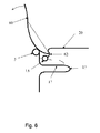
- Figure 6 is a lever open version of the closure of figure 1.
- The schematic side sections of figures 1 and 2 each comprise a can body of 0.16 mm tinplate terminating at the upper end of its
sidewall 3 in anoutward curl 5. The can body wall thickness could be in the range of 0.14 to 0.25 mm. Thesidewall 3 of each figure includes astep 10 which provides a shelf on which sealingcompound 12 is deposited. Aclosure 20 of 0.16 to 0.21 mm gauge tinplate or tin free steel is seated on theshelf 10 as shown. - In figure 1, the
step 10 comprises abead 15, which has been flattened so as to form a shelf of the order of 3 mm in width with a relatively flatupper surface 17 on which thesealing compound 12 is deposited whilst in a fluid state. The width and geometry of the shelf must be sufficient to allow for placement and curing of the compound without the liquid compound flowing over the edge of the shelf. - The
closure 20 is of thinner metal than the can body, typically 0.21 mm for an easy open end. The closure is placed on the fluid compound, thereby forming adepression 13 in the compound, which sets into this shape as the compound hardens. The lining of the example of figure 3 is 038 lining compound but other types may be suitable. - As shown in figure 3, the
lining compound 12 has been deposited as a liquid over the weld step 25 which it fills so as to provide a smooth surface for seating theclosure 20. - Similarly, the
step 10 of the can body of figure 2 forms a shelf for the fluid sealing compound onto which theclosure 20 is placed and formsdepression 13. - Alternative embodiments of the invention are shown in figures 4 and 5. Figure 4 is a similar side section to that of figure 1 with the can body terminating in an inwards
curl 5. Theclosure 30 comprises acentre panel 32, which extends radially outwardly into abead 34 and terminates in an radiallyoutward curl 36. Theclosure bead 34 is seated on the sealingcompound 12 on the upper surface ofshelf 17 as in the example of figure 1. Aplastic clip 40 clips over the pair ofcurls clip 40 extends radially inwardly into atab 38 for ease of opening. - In figure 5, the can body includes a
separate ring component 50 with astep 56 in the ring rather the can body wall itself. The ring is fixed to the can sidewall typically by a double seam, and then the can and ring combination are closed by, for example, a peelable panel. In figure 5, thering component 50 is shown with a seamingpanel 54, prior to seaming to the can body. The flat panel of theclosure 32 prevents the radius of the closure settling too deeply into the liningcompound 12, or cutting through the compound ontoshelf 56 itself. The closure disc has hemmed edges and is stuck to thelining compound 12 as described above, withtab 38 being folded back over the panel. - The lever open version of figure 6 has a
closure 20 which is similar to that of figure 1 and comprises a panel and an upright wall depending from the panel which terminates in a curl. The upright wall in the embodiment of figure 6 includes a groove 62 into which aspoon 60 or other lever can be inserted in order to lever the closure off sealingcompound 12 for opening of the container. - Numerous other embodiments are of course possible within the scope of the invention as defined by the claims.
Claims (13)
- A can body having a base and a sidewall, the can sidewall having a step or flange around its perimeter and sealing compound placed on the step which forms a seat for a closure.
- A can body according to claim 1, in which the step is an expanded part of the sidewall periphery.
- A can body according to claim 1, in which the step is a fold or flattened bead in the sidewall periphery.
- A can body according to any one of claims 1 to 3, in which the pliable material is a plastic, elastomeric material, sealing compound or rubber.
- A can body according to any one of claims 1 to 4, in which the sidewall includes a welded side seam and the pliable material covers the weld.
- A can body according to any one of claims 1 to 5, in which the edge of the sidewall is curled either outwardly or inwardly.
- A can body according to any one of claims 1 to 6, in which the sealing surface formed by the compound is uniform in height.
- In combination, the can body of any one of claims 1 to 7 and a recloseable end or closure which includes a vacuum release feature.
- In combination, the can body of any one of claims 1 to 7 and a recloseable end or closure which includes a tab.
- A method of forming a can body with a step in its sidewall, the method comprising, in the following order, the steps of:forming a curl in an edge of the can body's sidewall by die curling,beading the sidewall,forming a step andapplying a fluid pliable material on the step.
- A method of forming a can body with a step in its sidewall, the method comprising, in the following order, the steps of:beading the sidewall,forming a step in the sidewalls,forming a curl by spin curling andapplying a fluid pliable material on the step.
- A method according to claim 8, in which beading and step forming are carried out substantially simultaneously.
- A method according to any one of claims 7 to 9, further comprising placing a closure on the pliable material whilst the material is still fluid, thereby adhering the closure to the can body.
Priority Applications (2)
| Application Number | Priority Date | Filing Date | Title |
|---|---|---|---|
| EP05112915A EP1800770A1 (en) | 2005-12-23 | 2005-12-23 | Can body with a sealing compound placed on a step or flange and method of forming such a can body |
| PCT/EP2006/069926 WO2007071682A1 (en) | 2005-12-23 | 2006-12-19 | Can body with a sealing compound placed on a step or flange and method of forming such a can body |
Applications Claiming Priority (1)
| Application Number | Priority Date | Filing Date | Title |
|---|---|---|---|
| EP05112915A EP1800770A1 (en) | 2005-12-23 | 2005-12-23 | Can body with a sealing compound placed on a step or flange and method of forming such a can body |
Publications (1)
| Publication Number | Publication Date |
|---|---|
| EP1800770A1 true EP1800770A1 (en) | 2007-06-27 |
Family
ID=36679227
Family Applications (1)
| Application Number | Title | Priority Date | Filing Date |
|---|---|---|---|
| EP05112915A Withdrawn EP1800770A1 (en) | 2005-12-23 | 2005-12-23 | Can body with a sealing compound placed on a step or flange and method of forming such a can body |
Country Status (2)
| Country | Link |
|---|---|
| EP (1) | EP1800770A1 (en) |
| WO (1) | WO2007071682A1 (en) |
Cited By (4)
| Publication number | Priority date | Publication date | Assignee | Title |
|---|---|---|---|---|
| WO2013010875A1 (en) * | 2011-07-21 | 2013-01-24 | Crown Packaging Technology, Inc. | Metal cans with peelable lids |
| WO2014027180A1 (en) * | 2012-08-17 | 2014-02-20 | Crown Packaging Technology Inc | Metal cans with peelable lids |
| WO2016142677A1 (en) * | 2015-03-11 | 2016-09-15 | Crown Packaging Technology, Inc. | Ringless metal cans and method |
| CN106458397A (en) * | 2014-04-29 | 2017-02-22 | 苏德罗尼克股份公司 | Method and apparatus for manufacturing easy-open end and easy-open end |
Families Citing this family (1)
| Publication number | Priority date | Publication date | Assignee | Title |
|---|---|---|---|---|
| MX2018006957A (en) * | 2015-12-10 | 2018-11-09 | Novelis Inc | Inverted curling method for metal beverage containers and beverage containers with inverted curls. |
Citations (4)
| Publication number | Priority date | Publication date | Assignee | Title |
|---|---|---|---|---|
| FR2639561A1 (en) * | 1988-11-29 | 1990-06-01 | Carnaud Sa | Method of manufacturing a metal package having a flexible cover, and corresponding metal package |
| DE4038870A1 (en) * | 1990-09-11 | 1992-06-04 | Effem Gmbh | PRESSURE COVER CAN |
| WO1996007593A1 (en) * | 1994-09-10 | 1996-03-14 | Carnaudmetalbox Plc | Easy-open containers |
| EP0919482A1 (en) * | 1997-11-27 | 1999-06-02 | Nihon Seikan Kabushiki Kaisha | Metallic can and method of manufacture of same |
Family Cites Families (4)
| Publication number | Priority date | Publication date | Assignee | Title |
|---|---|---|---|---|
| US2019376A (en) * | 1934-09-12 | 1935-10-29 | Continental Can Co | Container for shoe polish |
| US3616962A (en) * | 1969-12-12 | 1971-11-02 | Sweetheart Plastics | Sealed container or cup |
| ES281496Y (en) * | 1984-09-07 | 1987-04-16 | Planas Pedragosa Pedro | PERFECTED METAL CONTAINER |
| EP1495980A1 (en) * | 2003-07-08 | 2005-01-12 | CONSAFE ApS | Container made of metal sheet material and having a shock absorbing closure |
-
2005
- 2005-12-23 EP EP05112915A patent/EP1800770A1/en not_active Withdrawn
-
2006
- 2006-12-19 WO PCT/EP2006/069926 patent/WO2007071682A1/en not_active Ceased
Patent Citations (4)
| Publication number | Priority date | Publication date | Assignee | Title |
|---|---|---|---|---|
| FR2639561A1 (en) * | 1988-11-29 | 1990-06-01 | Carnaud Sa | Method of manufacturing a metal package having a flexible cover, and corresponding metal package |
| DE4038870A1 (en) * | 1990-09-11 | 1992-06-04 | Effem Gmbh | PRESSURE COVER CAN |
| WO1996007593A1 (en) * | 1994-09-10 | 1996-03-14 | Carnaudmetalbox Plc | Easy-open containers |
| EP0919482A1 (en) * | 1997-11-27 | 1999-06-02 | Nihon Seikan Kabushiki Kaisha | Metallic can and method of manufacture of same |
Cited By (13)
| Publication number | Priority date | Publication date | Assignee | Title |
|---|---|---|---|---|
| US10329055B2 (en) | 2011-07-21 | 2019-06-25 | Crown Packaging Technology, Inc. | Metal cans with peelable lids |
| RU2566276C2 (en) * | 2011-07-21 | 2015-10-20 | Краун Пэкеджинг Текнолоджи, Инк. | Metal can with stripped lid |
| WO2013010875A1 (en) * | 2011-07-21 | 2013-01-24 | Crown Packaging Technology, Inc. | Metal cans with peelable lids |
| WO2014027180A1 (en) * | 2012-08-17 | 2014-02-20 | Crown Packaging Technology Inc | Metal cans with peelable lids |
| US9932152B2 (en) | 2012-08-17 | 2018-04-03 | Crown Packaging Technology, Inc. | Metal cans with peelable lids |
| CN106458397A (en) * | 2014-04-29 | 2017-02-22 | 苏德罗尼克股份公司 | Method and apparatus for manufacturing easy-open end and easy-open end |
| CN106458397B (en) * | 2014-04-29 | 2019-03-08 | 苏德罗尼克股份公司 | Method and apparatus for manufacturing easy-open lids and easy-open lids |
| WO2016142677A1 (en) * | 2015-03-11 | 2016-09-15 | Crown Packaging Technology, Inc. | Ringless metal cans and method |
| EP3543157A1 (en) * | 2015-03-11 | 2019-09-25 | Crown Packaging Technology, Inc. | Ringless metal cans |
| RU2713976C2 (en) * | 2015-03-11 | 2020-02-11 | Краун Пэкеджинг Текнолоджи, Инк. | Can, suitable for use with detachable cover (embodiments), can body (embodiments) and method of processing can body |
| US11084632B2 (en) | 2015-03-11 | 2021-08-10 | Crown Packaging Technology, Inc. | Ringless metal cans and method |
| JP2021181337A (en) * | 2015-03-11 | 2021-11-25 | クラウン・パッケージング・テクノロジー・インク | Ringless metal can and method for producing the same |
| JP7098029B2 (en) | 2015-03-11 | 2022-07-08 | クラウン・パッケージング・テクノロジー・インク | Ringless metal cans and their manufacturing methods |
Also Published As
| Publication number | Publication date |
|---|---|
| WO2007071682A1 (en) | 2007-06-28 |
Similar Documents
| Publication | Publication Date | Title |
|---|---|---|
| US20090032535A1 (en) | Container | |
| EP0683110B1 (en) | Container-lid combination | |
| EP1855822B1 (en) | Packaging can | |
| CA2573513C (en) | Composite containers and methods for sealing the same | |
| CN110650894B (en) | Containers for the hermetically sealed storage of products, especially foodstuffs | |
| EP1526090A2 (en) | Container with easily removable membrane lid | |
| EP0357276A1 (en) | Vacuum packed canned product and method using foil membrane end closure | |
| US20100301045A1 (en) | Method for forming a lid and such seamable lid itself | |
| US20080302756A1 (en) | Container | |
| EP1800770A1 (en) | Can body with a sealing compound placed on a step or flange and method of forming such a can body | |
| US20060191940A1 (en) | Sealing surfaces for container end panels | |
| JP2942520B2 (en) | Substantially circular end seal lid used for substantially cylindrical containers | |
| US3208626A (en) | Container closure and package including same | |
| US20090014448A1 (en) | Can comprising a foil seal | |
| JP2002178072A (en) | Can lid | |
| CA2583917A1 (en) | Reclosable foil lid | |
| AU2005206169A1 (en) | Angled sealing surface for container end panel | |
| EP4054946B1 (en) | Metal container and metal closure thereof | |
| US20240409282A1 (en) | Resealable can closure system | |
| JP2001170730A (en) | Cap for metal container, metal container, and method for manufacturing metal container | |
| US20240409283A1 (en) | Resealable can closure system | |
| CA2589742C (en) | Method of and apparatus for forming a closure | |
| WO2010094780A1 (en) | Metal end panel with hole | |
| GB2065593A (en) | Attaching metal closures to plastics containers | |
| WO2025016943A1 (en) | Overcap |
Legal Events
| Date | Code | Title | Description |
|---|---|---|---|
| PUAI | Public reference made under article 153(3) epc to a published international application that has entered the european phase |
Free format text: ORIGINAL CODE: 0009012 |
|
| AK | Designated contracting states |
Kind code of ref document: A1 Designated state(s): AT BE BG CH CY CZ DE DK EE ES FI FR GB GR HU IE IS IT LI LT LU LV MC NL PL PT RO SE SI SK TR |
|
| AX | Request for extension of the european patent |
Extension state: AL BA HR MK YU |
|
| STAA | Information on the status of an ep patent application or granted ep patent |
Free format text: STATUS: THE APPLICATION HAS BEEN WITHDRAWN |
|
| 18W | Application withdrawn |
Effective date: 20070813 |