EP1800759A1 - Metal powder production apparatus - Google Patents
Metal powder production apparatus Download PDFInfo
- Publication number
- EP1800759A1 EP1800759A1 EP06026429A EP06026429A EP1800759A1 EP 1800759 A1 EP1800759 A1 EP 1800759A1 EP 06026429 A EP06026429 A EP 06026429A EP 06026429 A EP06026429 A EP 06026429A EP 1800759 A1 EP1800759 A1 EP 1800759A1
- Authority
- EP
- European Patent Office
- Prior art keywords
- orifice
- metal powder
- nozzle
- production apparatus
- powder production
- Prior art date
- Legal status (The legal status is an assumption and is not a legal conclusion. Google has not performed a legal analysis and makes no representation as to the accuracy of the status listed.)
- Granted
Links
Images
Classifications
-
- B—PERFORMING OPERATIONS; TRANSPORTING
- B22—CASTING; POWDER METALLURGY
- B22F—WORKING METALLIC POWDER; MANUFACTURE OF ARTICLES FROM METALLIC POWDER; MAKING METALLIC POWDER; APPARATUS OR DEVICES SPECIALLY ADAPTED FOR METALLIC POWDER
- B22F9/00—Making metallic powder or suspensions thereof
- B22F9/02—Making metallic powder or suspensions thereof using physical processes
- B22F9/06—Making metallic powder or suspensions thereof using physical processes starting from liquid material
- B22F9/08—Making metallic powder or suspensions thereof using physical processes starting from liquid material by casting, e.g. through sieves or in water, by atomising or spraying
-
- B—PERFORMING OPERATIONS; TRANSPORTING
- B22—CASTING; POWDER METALLURGY
- B22F—WORKING METALLIC POWDER; MANUFACTURE OF ARTICLES FROM METALLIC POWDER; MAKING METALLIC POWDER; APPARATUS OR DEVICES SPECIALLY ADAPTED FOR METALLIC POWDER
- B22F9/00—Making metallic powder or suspensions thereof
- B22F9/02—Making metallic powder or suspensions thereof using physical processes
- B22F9/06—Making metallic powder or suspensions thereof using physical processes starting from liquid material
- B22F9/08—Making metallic powder or suspensions thereof using physical processes starting from liquid material by casting, e.g. through sieves or in water, by atomising or spraying
- B22F9/082—Making metallic powder or suspensions thereof using physical processes starting from liquid material by casting, e.g. through sieves or in water, by atomising or spraying atomising using a fluid
Definitions
- the present invention relates to a metal powder production apparatus for producing metal powder from molten metal.
- a metal powder production apparatus that pulverizes molten metal into metal powder by an atomizing method has been used in producing metal powder.
- the metal powder production apparatus known in the art include a molten metal atomizing and pulverizing apparatus disclosed in JP-B-3-55522 .
- the molten metal atomizing and pulverizing apparatus is provided with a molten bath nozzle for ejecting molten bath (molten metal) in a downward direction and a water nozzle having a flow path through which the molten bath ejected from the molten bath nozzle passes and a slit opened into the flow path. Water is injected from the slit of the water nozzle.
- the apparatus of the prior art mentioned above is designed to produce metal powder by bringing the molten bath passing through the flow path into collision with the water injected from the slit to thereby disperse the molten bath in the form of a multiplicity of fine liquid droplets and then allowing the multiplicity of fine liquid droplets to be cooled and solidified.
- the metal powder production apparatus comprises a supply part for supplying molten metal and a nozzle provided below the supply part.
- the nozzle includes a flow path defined by an inner circumferential surface of the nozzle through which the molten metal supplied from the supply part can pass, the flow path having a gradually reducing inner diameter portion whose inner diameter is gradually reduced in a downward direction, and an orifice opened at a bottom end of the flow path and adapted to inject fluid toward the flow path.
- the molten metal is dispersed and turned into a multiplicity of fine liquid droplets by bringing the molten metal passing through the flow path into contact with the fluid injected from the orifice of the nozzle, so that the multiplicity of fine liquid droplets are solidified to thereby produce metal powder.
- the nozzle includes a first member and a second member provided below the first member with a space left between the first member and the second member.
- the orifice is defined by the first member and the second member.
- a restraint means for restraining the orifice from being enlarged by the pressure of the fluid passing through the orifice is provided on the nozzle.
- the orifice is opened in a circumferential slit shape extending over the inner circumferential surface of the nozzle.
- the orifice has an inner circumferential surface defined by an end portion of the first member and an outer circumferential surface defined by an end portion of the second member.
- the size of the orifice can be properly set in accordance with the size of the space left between the first member and the second member.
- the orifice is configured to ensure that the fluid is injected in a generally conical contour with an apex lying at a lower side.
- the nozzle further includes a retention portion for temporarily retaining the fluid, and an introduction path for introducing the fluid from the retention portion to the orifice, the introduction path having a vertical cross-section of a wedge shape.
- the gradually reducing inner diameter portion is of a convergent shape.
- the restraint means is capable of adjusting a degree of restraint imposed on the orifice.
- the restraint means comprises a clamp for gripping and compressing the first member and the second member in a generally vertical direction.
- the clamp includes two gripper pieces respectively arranged at a top region of the first member and at a bottom region of the second member and a connector portion for interconnecting the two gripper pieces, the connector portion capable of adjusting a spacing between the gripper pieces.
- the clamp includes a plurality of clamps arranged around a center axis of the flow path with a predetermined spacing.
- the restraint means comprises a clamp for compressing the first member and the second member in a generally horizontal direction.
- the clamp is adapted to generally uniformly tighten entire circumferences of outer periphery portions of the first member and the second member.
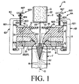
- Fig. 1 is a vertical sectional view showing a metal powder production apparatus in accordance with a first embodiment of the present invention.
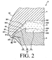
- Fig. 2 is an enlarged detail view of a region [A] enclosed by a single-dotted chain line in Fig. 1.
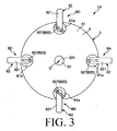
- Fig. 3 is a plan (top) view of the metal powder production apparatus shown in Fig. 1.
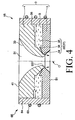
- Fig. 4 is a vertical sectional view showing a metal powder production apparatus in accordance with a second embodiment of the present invention.
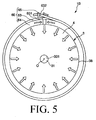
- Fig. 5 is a plan (top) view of the metal powder production apparatus shown in Fig. 4.
- Fig. 1 is a vertical sectional view showing a metal powder production apparatus in accordance with a first embodiment of the present invention
- Fig. 2 is an enlarged detail view of a region [A] enclosed by a single-dotted chain line in Fig. 1
- Fig. 3 is a plan (top) view of the metal powder production apparatus shown in Fig. 1.
- Figs. 1 and 2 will be referred to as “top” or “upper” and the lower side will be referred to as “bottom” or “lower”, only for the sake of better understanding.
- Fig. 3 a supply part is omitted from illustration.
- the metal powder production apparatus (atomizer) 1A shown in Fig. 1 is an apparatus that pulverizes molten metal Q by an atomizing method to obtain a multiplicity of metal powder particles R.
- the metal powder production apparatus 1A includes a supply part 2 for supplying the molten metal Q, a nozzle 3 provided below the supply part 2, clamps (restraint means) 6A, 6B, 6C and 6D attached to the nozzle 3 and a cover 7 attached to a bottom end surface 51 of the nozzle 3 (a second member 5).
- the metal powder production apparatus 1A produces metal powder particles R made of stainless steel (e.g., 304L, 316L, 17-4PH, 440C or the like) or Fe-Si-based magnetic material.
- metal powder particles R made of stainless steel (e.g., 304L, 316L, 17-4PH, 440C or the like) or Fe-Si-based magnetic material.
- the supply part 2 has a portion of a bottom-closed tubular shape.
- an internal space (cavity portion) 22 of the supply part 2 there is temporarily stored the molten metal Q (a molten material) obtained by mixing a simple substance of Co and a simple substance of Sn at a predetermined mol ratio (e.g., a mol ratio of 1:2) and melting them.
- a predetermined mol ratio e.g., a mol ratio of 1:2
- an ejection port 23 is formed at the center of a bottom portion 21 of the supply part 2.
- the molten metal Q in the internal space 22 is downwardly ejected from the ejection port 23.
- the nozzle 3 is arranged below the supply part 2.
- the nozzle 3 is provided with a first flow path 31 through which the molten metal Q supplied (ejected) from the supply part 2 passes and a second flow path 32 through which water S supplied from a water source (not shown) for supplying fluid (water or liquid S in the present embodiment) passes.
- the first flow path 31 has a circular cross-section and extends in a vertical direction at the center of the nozzle 3.
- the first flow path 31 is defined by an inner circumferential surface of the nozzle 3.
- the first flow path 31 has a gradually reducing inner diameter portion 33 of a convergent shape whose inner diameter is gradually decreased from a top end surface 41 of the nozzle 3 (a first member 4) toward the bottom thereof.
- the air (gas) G subsisting above the nozzle 3 flows into (or is sucked up into) the gradually reducing inner diameter portion 33 (the first flow path 31) together with the stream of water (fluid) S injected from an orifice 34, which will be describe later.
- the air G thus introduced exhibits a greatest flow velocity near a smallest inner diameter section 331 of the gradually reducing inner diameter portion 33 (near a section at which the orifice 34 is opened). Under an action of the air G whose flow velocity has become greatest, the molten metal Q is dispersed and turned to a multiplicity of fine liquid droplets Q1 in a reliable manner.
- the second flow path 32 is formed of an orifice 34 opened toward a bottom end portion (the vicinity of the smallest inner diameter section 331) of the first flow path 31, a retention portion 35 for temporarily retaining the water S, and an introduction path (interconnecting path) 36 through which the water S is introduced from the retention portion 35 into the orifice 34.
- the retention portion 35 is connected to the water source to receive the water S therefrom.
- the retention portion 35 communicates with the orifice 34 through the introduction path 36. Furthermore, the retention portion 35 has a vertical cross-section of a rectangular (or square) shape.
- the introduction path 36 is a region whose vertical cross-section is of a wedge-like shape. This makes it possible to gradually increase the flow velocity of the water S flowing into the introduction path 36 from the retention portion 35 and, hence, to stably inject the water S with an increased flow velocity from the orifice 34.
- the orifice 34 is a region at which the water S passed the retention portion 35 and the introduction path 36 in sequence is injected or spouted into the first flow path 31.
- the orifice 34 is opened in a circumferential slit shape extending over the inner circumferential surface of the nozzle 3. Furthermore, the orifice 34 is opened in an inclined direction with respect to a center axis O of the first flow path 31.
- the water S is injected as a liquid jet S1 of a generally conical contour with an apex S2 thereof lying definitely at the lower side (see Fig. 1). This ensures that, in and inside the liquid jet S1, the molten metal Q is dispersed and turned to the multiplicity of fine liquid droplets Q1 in a reliable manner.
- the molten metal Q is further dispersed and turned to the multiplicity of fine liquid droplets Q1 in a reliable manner, by the Air G whose flow velocity becomes greatest near the smallest inner diameter section 331 of the gradually reducing inner diameter portion 33. This generates a synergistic effect by which the molten metal Q is reliably dispersed and turned to the multiplicity of fine liquid droplets Q1 in more reliable manner.
- the molten metal Q turned to the multiplicity of liquid droplets Q1 is cooled and solidified by making contact with the liquid jet S1, whereby a multiplicity of metal powder particles R are produced.
- the multiplicity of metal powder particles R thus produced are received in a container (not shown) arranged below the metal powder production apparatus 1A.
- the nozzle 3 in which the first flow path 31 and the second flow path 32 are formed includes a first member 4 of a disk-like shape (ring-like shape) and a second member 5 of a disk-like shape (ring-like shape) arranged concentrically with the first member 4 (see Figs. 1 and 2).
- the second member 5 is arranged below the first member 4 with a space 37 left therebetween.
- the orifice 34, the introduction path 36 and the retention portion 35 are respectively defined by the first member 4 and the second member 5 arranged in this way. That is to say, the second flow path 32 is provided by the space 37 formed between the first member 4 and the second member 5.
- the orifice 34 has an inner circumferential surface 341 defined by a bottom end surface (end portion) 42 of the first member 4 and an outer circumferential surface 342 defined by a top end surface (end portion) 52 of the second member 5.
- the introduction path 36 has an upper surface 361 defined by the bottom end surface (end portion) 42 of the first member 4 and a lower surface 362 defined by the top end surface (end portion) 52 of the second member 5.
- the retention portion 35 has an upper surface 351 and an inner circumferential surface 352 lying above the introduction path 36, both of which are defined by the bottom end surface (end portion) 42 of the first member 4, and a lower surface 353 and an inner circumferential surface 354 lying below the introduction path 36, both of which are defined by the top end surface (end portion) 52 of the second member 5.
- the orifice 34, the introduction path 36 and the retention portion 35 By defining the orifice 34, the introduction path 36 and the retention portion 35 in this manner, it is possible to easily and reliably form the orifice 34, the introduction path 36 and the retention portion 35 in the nozzle 3. Furthermore, the size of the orifice 34, the introduction path 36 and the retention portion 35 can be properly set in accordance with the size of the space 37.
- Examples of a constituent material of the first member 4 and the second member 5 include, but are not particularly limited to, a variety of metallic materials.
- use of stainless steel is preferred, and use of Cr-based stainless steel or precipitation hardening stainless steel is more preferred.
- the cover 7 formed of a tubular body is fixedly secured to a bottom end surface 51 of the second member 5.
- the cover 7 is arranged concentrically with the first flow path 31. Use of the cover 7 makes it possible to prevent the metal powder particles R from flying apart as they fall down, whereby the metal powder particles R can be reliably received the container.
- each of the clamps 6A, 6B, 6C and 6D is adapted to grip and compress the first member 4 and the second member 5 in a generally vertical direction (up-and-down direction in Fig. 1).
- the four clamps 6A, 6B, 6C and 6D are arranged along a perimeter of the nozzle 3, namely around the center axis O of the first flow path 31, with a predetermined spacing (at an equal angular spacing). This makes it possible to uniformly compress the first member 4 and the second member 5 in the vertical direction.
- clamp 6A Inasmuch as the four clamps 6A, 6B, 6C and 6D have substantially the same configuration, only the clamp 6A will be representatively described in the following.
- the clamp 6A includes two gripper pieces 61a and 61b and a connector portion 62 for interconnecting the two gripper pieces 61a and 61b.
- Each of the gripper pieces 61a and 61b is formed of a disk-like member.
- the connector portion 62 is comprised of a connector portion main body 621 with a female thread 624 and an operating part 622 with a male thread 623 threadedly coupled with the female thread 624.
- the connector portion main body 621 is of a generally "C"-like shape.
- the female thread 624 is formed at one end 625 of the connector portion main body 621.
- the gripper piece 61b is provided at the other end 626 of the connector portion main body 621.
- the operating part 622 has a handle 627, on the opposing side of which the gripper piece 61a is provided.
- the clamp 6A of this configuration is attached to the nozzle 3 in such a posture that the gripper pieces 61a and 61b are confronted with each other in an up-and-down direction.
- the gripper piece 61a is arranged at the edge region of the top end surface (top portion) 41 of the first member 4, while the gripper piece 61b is arranged at the edge region of the bottom end surface (bottom portion) 51 of the second member 5.
- the metal powder production apparatus 1A As configured above, when the water S is injected from the orifice 34, the inner circumferential surface 341 is pushed in the direction indicated by an arrow "B" and the outer circumferential surface 342 is pushed in the direction indicated by an arrow C, by the pressure of the water S passing through the orifice 34. Thus, the orifice 34 is urged to become enlarged. However, enlargement of the orifice 34 is prevented because the clearance (space) between the inner circumferential surface 341 and the outer circumferential surface 342 is restrained by the compressing action of the clamps 6A, 6B, 6C and 6D.
- the spacing L between the gripper pieces 61a and 61b can be adjusted by rotatingly operating the handle 627. This makes it possible to reliably adjust the compression force acting against the nozzle 3, i.e., the degree of restraint imposed on the orifice 34.
- powder of a fine particle size can be produced by stabilizing the flow velocity of an injected fluid.
- the clamps 6A, 6B, 6C and 6D are arranged along a perimeter of the nozzle 3 with a predetermined spacing. This makes it possible to uniformly compress the first member 4 and the second member 5 in the vertical direction, whereby the flow velocity of the water S injected from the orifice 34 can be kept constant in a reliable manner.
- clamps Although four clamps are employed in the illustrated configuration, the number of clamps is not limited thereto and may be, e.g., two, three or more than five.
- examples of a constituent material of the gripper pieces 61a and 61b, the connector portion main body 621 and the operating part 622 include, but are not particularly limited to, a variety of metallic materials or various kinds of plastics, which may be used independently or in combination.
- Fig. 4 is a vertical sectional view showing a metal powder production apparatus in accordance with a second embodiment of the present invention
- Fig. 5 is a plan (top) view of the metal powder production apparatus shown in Fig. 4.
- the present embodiment is the same as the first embodiment, except for difference in the configuration of a clamp.
- the metal powder production apparatus 1B shown in Figs. 4 and 5, includes a clamp (restraint means) 6E provided along an outer periphery portion 38 of the nozzle 3.
- the clamp 6E is adapted to compress the first member 4 and the second member 5 in a generally horizontal direction (in a left-right direction in Fig. 4).
- the clamp 6E includes a flexible linear body 63, a flexible band-like body 64 and a connector member 65 for joining one end 631 and the other end 632 of the linear body 63.
- the band-like body 64 has a width substantially equal to the width (height) of the nozzle 3 and a length set slightly smaller than the length (circumference) of the outer periphery portion 38 of the nozzle 3.
- the band-like body 64 is provided in close contact with the outer periphery portion 38 of the nozzle 3.
- the linear body 63 is formed of, e.g., a wire, and is wound around the band-like body 64 in multiple times.
- the connector portion 65 is fixedly secured to one end 631 of the linear body 63 and is configured such that it can grip an arbitrary portion of the other end 632 of the linear body 63 and can maintain that portion in the gripped condition.
- the band-like body 64 is placed along the outer periphery portion 38 of the nozzle 3 and, then, the linear body 63 is wound around and tightened against the band-like body 64. In this state, the other end 632 of the linear body 63 is gripped by the connector portion 65. This makes it possible to uniformly tighten the nearly entire circumference of the outer periphery portion 38 of the nozzle 3, thereby reliably restraining any enlargement of the orifice 34.
- the operating parts 622 of the clamps 6A, 6B, 6C and 6D are operated one by one when compressing the nozzle 3.
- the task of compressing the nozzle 3 can be conducted merely by interconnecting the other end 632 of the linear body 63 and the connector portion 65.
- the clamp 6E of the present embodiment makes it possible to easily and more uniformly compress the nozzle 3.
- Examples of a constituent material of the linear body 63, the band-like body 64 and the connector portion 65 include a variety of metallic materials.
- the clamp 6E has one linear body 63 configured to collectively compress both the first member 4 and the second member 5, the present invention is not limited thereto.
- the clamp 6E may be provided with, e.g., two linear bodies configured to separately compress the first member 4 and the second member 5. Even if the clamp 6E has two linear bodies in this way, it is possible to easily and more uniformly compress the nozzle 3.
- the present invention is not limited thereto. Individual parts constituting the metal powder production apparatus may be substituted by other arbitrary ones capable of performing like functions. Moreover, arbitrary constituent parts may be added if necessary.
- the metal powder production apparatus of the present invention may be constructed by combining two or more arbitrary configurations (features) of the respective embodiments described above.
- the clamp of the second embodiment may be added to the nozzle of the first embodiment.
- liquid (fluid) injected from the nozzle is water in the foregoing embodiments, the present invention is not limited thereto.
- the liquid may be, e.g., lipids or solvents.
Landscapes
- Manufacture Of Metal Powder And Suspensions Thereof (AREA)
- Nozzles (AREA)
Abstract
Description
- This application claims a priority to
Japanese Patent Application No. 2005-367227 filed on December 20, 2005 - The present invention relates to a metal powder production apparatus for producing metal powder from molten metal.
- Conventionally, a metal powder production apparatus (atomizer) that pulverizes molten metal into metal powder by an atomizing method has been used in producing metal powder. Examples of the metal powder production apparatus known in the art include a molten metal atomizing and pulverizing apparatus disclosed in
JP-B-3-55522 - The molten metal atomizing and pulverizing apparatus is provided with a molten bath nozzle for ejecting molten bath (molten metal) in a downward direction and a water nozzle having a flow path through which the molten bath ejected from the molten bath nozzle passes and a slit opened into the flow path. Water is injected from the slit of the water nozzle.
- The apparatus of the prior art mentioned above is designed to produce metal powder by bringing the molten bath passing through the flow path into collision with the water injected from the slit to thereby disperse the molten bath in the form of a multiplicity of fine liquid droplets and then allowing the multiplicity of fine liquid droplets to be cooled and solidified.
- However, in the apparatus of the prior art mentioned above, the clearance of the slit is excessively enlarged by the pressure of the water flowing therethrough. As a result, water pressure is dropped in the water nozzle. This water pressure drop causes a problem of overly reducing the flow velocity of the water injected from the slit. Therefore, since the ability for the fast-flowing water to pulverize the molten bath is decreased, fine-sizing of the metal powder cannot be made. This makes it difficult to obtain fine powder of a desired particle size.
- Accordingly, it is an object of the present invention to provide a metal powder production apparatus capable of maintaining a flow velocity of fluid injected from an orifice nearly constant in a reliable manner.
- One aspect of the invention is directed to a metal powder production apparatus. The metal powder production apparatus comprises a supply part for supplying molten metal and a nozzle provided below the supply part. The nozzle includes a flow path defined by an inner circumferential surface of the nozzle through which the molten metal supplied from the supply part can pass, the flow path having a gradually reducing inner diameter portion whose inner diameter is gradually reduced in a downward direction, and an orifice opened at a bottom end of the flow path and adapted to inject fluid toward the flow path.
- The molten metal is dispersed and turned into a multiplicity of fine liquid droplets by bringing the molten metal passing through the flow path into contact with the fluid injected from the orifice of the nozzle, so that the multiplicity of fine liquid droplets are solidified to thereby produce metal powder.
- Further, the nozzle includes a first member and a second member provided below the first member with a space left between the first member and the second member. The orifice is defined by the first member and the second member. A restraint means for restraining the orifice from being enlarged by the pressure of the fluid passing through the orifice is provided on the nozzle.
- This makes it possible to maintain the flow velocity of the fluid injected from the orifice nearly constant in a reliable manner.
- It is preferred that the orifice is opened in a circumferential slit shape extending over the inner circumferential surface of the nozzle.
- This ensures that the fluid is injected in a generally conical contour with an apex thereof lying definitely at the lower side.
- It is preferred that the orifice has an inner circumferential surface defined by an end portion of the first member and an outer circumferential surface defined by an end portion of the second member.
- This makes it possible to easily and reliably form the orifice. Furthermore, the size of the orifice can be properly set in accordance with the size of the space left between the first member and the second member.
- It is preferred that the orifice is configured to ensure that the fluid is injected in a generally conical contour with an apex lying at a lower side.
- This ensures that the molten metal is dispersed within the fluid injected in a generally conical contour and is turned to a multiplicity of fine liquid droplets in a reliable manner.
- It is preferred that the nozzle further includes a retention portion for temporarily retaining the fluid, and an introduction path for introducing the fluid from the retention portion to the orifice, the introduction path having a vertical cross-section of a wedge shape.
- This makes it possible to gradually increase the flow velocity of the fluid. It is also possible to stably inject the fluid having an increased velocity from the orifice.
- It is preferred that the gradually reducing inner diameter portion is of a convergent shape.
- This ensures that the air subsisting above the nozzle flows into (or is sucked up into) the gradually reducing inner diameter portion together with the stream of fluid injected from an orifice. The air thus introduced exhibits a greatest flow velocity near a smallest inner diameter section of the gradually reducing inner diameter portion. Under an action of the air whose flow velocity has become greatest, the molten metal is dispersed and turned to a multiplicity of fine liquid droplets in a reliable manner.
- It is preferred that the restraint means is capable of adjusting a degree of restraint imposed on the orifice.
- This makes it possible to stabilize the velocity of the fluid injected, thereby producing powder particles of a fine particle size.
- It is preferred that the restraint means comprises a clamp for gripping and compressing the first member and the second member in a generally vertical direction.
- This ensures that the first member and the second member are reliably compressed and enlargement of the orifice is restrained in a reliable manner, whereby the flow velocity of the fluid injected from the orifice can be kept nearly constant in a reliable manner.
- It is preferred that the clamp includes two gripper pieces respectively arranged at a top region of the first member and at a bottom region of the second member and a connector portion for interconnecting the two gripper pieces, the connector portion capable of adjusting a spacing between the gripper pieces.
- This ensures that the first member and the second member are reliably compressed and enlargement of the orifice is restrained in a reliable manner, whereby the flow velocity of the fluid injected from the orifice can be kept nearly constant in a reliable manner.
- It is preferred that the clamp includes a plurality of clamps arranged around a center axis of the flow path with a predetermined spacing.
- This makes it possible to uniformly compress the first member and the second member in a vertical direction, whereby the flow velocity of the fluid injected from the orifice can be kept nearly constant in more reliable manner.
- It is preferred that the restraint means comprises a clamp for compressing the first member and the second member in a generally horizontal direction.
- This makes it possible to uniformly compress the first member and the second member in a horizontal direction, whereby the flow velocity of the fluid injected from the orifice can be kept nearly constant in more reliable manner.
- It is preferred that the clamp is adapted to generally uniformly tighten entire circumferences of outer periphery portions of the first member and the second member.
- This makes it possible to uniformly compress the first member and the second member in a horizontal direction, whereby the flow velocity of the fluid injected from the orifice can be kept nearly constant in more reliable manner.
- The above and other objects, features and advantages of the present invention will become apparent from the following description of preferred embodiments given in conjunction with the accompanying drawings.
- Fig. 1 is a vertical sectional view showing a metal powder production apparatus in accordance with a first embodiment of the present invention.
- Fig. 2 is an enlarged detail view of a region [A] enclosed by a single-dotted chain line in Fig. 1.
- Fig. 3 is a plan (top) view of the metal powder production apparatus shown in Fig. 1.
- Fig. 4 is a vertical sectional view showing a metal powder production apparatus in accordance with a second embodiment of the present invention.
- Fig. 5 is a plan (top) view of the metal powder production apparatus shown in Fig. 4.
- Hereinafter, a metal powder production apparatus in accordance with the present invention will be described in respect of preferred embodiments shown in the accompanying drawings.
- Fig. 1 is a vertical sectional view showing a metal powder production apparatus in accordance with a first embodiment of the present invention, Fig. 2 is an enlarged detail view of a region [A] enclosed by a single-dotted chain line in Fig. 1, and Fig. 3 is a plan (top) view of the metal powder production apparatus shown in Fig. 1.
- In the following description, the upper side in Figs. 1 and 2 will be referred to as "top" or "upper" and the lower side will be referred to as "bottom" or "lower", only for the sake of better understanding. In Fig. 3, a supply part is omitted from illustration.
- The metal powder production apparatus (atomizer) 1A shown in Fig. 1 is an apparatus that pulverizes molten metal Q by an atomizing method to obtain a multiplicity of metal powder particles R. The metal
powder production apparatus 1A includes a supply part 2 for supplying the molten metal Q, anozzle 3 provided below the supply part 2, clamps (restraint means) 6A, 6B, 6C and 6D attached to thenozzle 3 and a cover 7 attached to abottom end surface 51 of the nozzle 3 (a second member 5). - Taken as an example in the present embodiment is a case that the metal
powder production apparatus 1A produces metal powder particles R made of stainless steel (e.g., 304L, 316L, 17-4PH, 440C or the like) or Fe-Si-based magnetic material. - Now, description will be given to the configuration of individual parts.
- As shown in Fig. 1, the supply part 2 has a portion of a bottom-closed tubular shape. In an internal space (cavity portion) 22 of the supply part 2, there is temporarily stored the molten metal Q (a molten material) obtained by mixing a simple substance of Co and a simple substance of Sn at a predetermined mol ratio (e.g., a mol ratio of 1:2) and melting them.
- Furthermore, an
ejection port 23 is formed at the center of abottom portion 21 of the supply part 2. The molten metal Q in theinternal space 22 is downwardly ejected from theejection port 23. - The
nozzle 3 is arranged below the supply part 2. Thenozzle 3 is provided with afirst flow path 31 through which the molten metal Q supplied (ejected) from the supply part 2 passes and asecond flow path 32 through which water S supplied from a water source (not shown) for supplying fluid (water or liquid S in the present embodiment) passes. - The
first flow path 31 has a circular cross-section and extends in a vertical direction at the center of thenozzle 3. Thefirst flow path 31 is defined by an inner circumferential surface of thenozzle 3. Thefirst flow path 31 has a gradually reducinginner diameter portion 33 of a convergent shape whose inner diameter is gradually decreased from atop end surface 41 of the nozzle 3 (a first member 4) toward the bottom thereof. - Thus, the air (gas) G subsisting above the
nozzle 3 flows into (or is sucked up into) the gradually reducing inner diameter portion 33 (the first flow path 31) together with the stream of water (fluid) S injected from anorifice 34, which will be describe later. The air G thus introduced exhibits a greatest flow velocity near a smallestinner diameter section 331 of the gradually reducing inner diameter portion 33 (near a section at which theorifice 34 is opened). Under an action of the air G whose flow velocity has become greatest, the molten metal Q is dispersed and turned to a multiplicity of fine liquid droplets Q1 in a reliable manner. - As illustrated in Fig. 2, the
second flow path 32 is formed of anorifice 34 opened toward a bottom end portion (the vicinity of the smallest inner diameter section 331) of thefirst flow path 31, aretention portion 35 for temporarily retaining the water S, and an introduction path (interconnecting path) 36 through which the water S is introduced from theretention portion 35 into theorifice 34. - The
retention portion 35 is connected to the water source to receive the water S therefrom. Theretention portion 35 communicates with theorifice 34 through theintroduction path 36. Furthermore, theretention portion 35 has a vertical cross-section of a rectangular (or square) shape. - The
introduction path 36 is a region whose vertical cross-section is of a wedge-like shape. This makes it possible to gradually increase the flow velocity of the water S flowing into theintroduction path 36 from theretention portion 35 and, hence, to stably inject the water S with an increased flow velocity from theorifice 34. - The
orifice 34 is a region at which the water S passed theretention portion 35 and theintroduction path 36 in sequence is injected or spouted into thefirst flow path 31. - The
orifice 34 is opened in a circumferential slit shape extending over the inner circumferential surface of thenozzle 3. Furthermore, theorifice 34 is opened in an inclined direction with respect to a center axis O of thefirst flow path 31. - By virtue of the
orifice 34 formed in this manner, the water S is injected as a liquid jet S1 of a generally conical contour with an apex S2 thereof lying definitely at the lower side (see Fig. 1). This ensures that, in and inside the liquid jet S1, the molten metal Q is dispersed and turned to the multiplicity of fine liquid droplets Q1 in a reliable manner. - As set forth above, the molten metal Q is further dispersed and turned to the multiplicity of fine liquid droplets Q1 in a reliable manner, by the Air G whose flow velocity becomes greatest near the smallest
inner diameter section 331 of the gradually reducinginner diameter portion 33. This generates a synergistic effect by which the molten metal Q is reliably dispersed and turned to the multiplicity of fine liquid droplets Q1 in more reliable manner. - The molten metal Q turned to the multiplicity of liquid droplets Q1 is cooled and solidified by making contact with the liquid jet S1, whereby a multiplicity of metal powder particles R are produced. The multiplicity of metal powder particles R thus produced are received in a container (not shown) arranged below the metal
powder production apparatus 1A. - The
nozzle 3 in which thefirst flow path 31 and thesecond flow path 32 are formed includes afirst member 4 of a disk-like shape (ring-like shape) and asecond member 5 of a disk-like shape (ring-like shape) arranged concentrically with the first member 4 (see Figs. 1 and 2). Thesecond member 5 is arranged below thefirst member 4 with aspace 37 left therebetween. - The
orifice 34, theintroduction path 36 and theretention portion 35 are respectively defined by thefirst member 4 and thesecond member 5 arranged in this way. That is to say, thesecond flow path 32 is provided by thespace 37 formed between thefirst member 4 and thesecond member 5. - As illustrated in Fig. 2, the
orifice 34 has an innercircumferential surface 341 defined by a bottom end surface (end portion) 42 of thefirst member 4 and an outercircumferential surface 342 defined by a top end surface (end portion) 52 of thesecond member 5. - Likewise, the
introduction path 36 has anupper surface 361 defined by the bottom end surface (end portion) 42 of thefirst member 4 and alower surface 362 defined by the top end surface (end portion) 52 of thesecond member 5. - Moreover, the
retention portion 35 has anupper surface 351 and an innercircumferential surface 352 lying above theintroduction path 36, both of which are defined by the bottom end surface (end portion) 42 of thefirst member 4, and alower surface 353 and an innercircumferential surface 354 lying below theintroduction path 36, both of which are defined by the top end surface (end portion) 52 of thesecond member 5. - By defining the
orifice 34, theintroduction path 36 and theretention portion 35 in this manner, it is possible to easily and reliably form theorifice 34, theintroduction path 36 and theretention portion 35 in thenozzle 3. Furthermore, the size of theorifice 34, theintroduction path 36 and theretention portion 35 can be properly set in accordance with the size of thespace 37. - Examples of a constituent material of the
first member 4 and thesecond member 5 include, but are not particularly limited to, a variety of metallic materials. In particular, use of stainless steel is preferred, and use of Cr-based stainless steel or precipitation hardening stainless steel is more preferred. - As shown in Fig. 1, the cover 7 formed of a tubular body is fixedly secured to a
bottom end surface 51 of thesecond member 5. The cover 7 is arranged concentrically with thefirst flow path 31. Use of the cover 7 makes it possible to prevent the metal powder particles R from flying apart as they fall down, whereby the metal powder particles R can be reliably received the container. - In the meantime, as depicted in Figs. 1 and 3, four
clamps nozzle 3. Each of the clamps 6A, 6B, 6C and 6D is adapted to grip and compress thefirst member 4 and thesecond member 5 in a generally vertical direction (up-and-down direction in Fig. 1). - Furthermore, the four
clamps nozzle 3, namely around the center axis O of thefirst flow path 31, with a predetermined spacing (at an equal angular spacing). This makes it possible to uniformly compress thefirst member 4 and thesecond member 5 in the vertical direction. - Inasmuch as the four
clamps clamp 6A will be representatively described in the following. - The
clamp 6A includes twogripper pieces connector portion 62 for interconnecting the twogripper pieces gripper pieces - The
connector portion 62 is comprised of a connector portionmain body 621 with afemale thread 624 and anoperating part 622 with amale thread 623 threadedly coupled with thefemale thread 624. - The connector portion
main body 621 is of a generally "C"-like shape. Thefemale thread 624 is formed at oneend 625 of the connector portionmain body 621. Thegripper piece 61b is provided at theother end 626 of the connector portionmain body 621. - The operating
part 622 has ahandle 627, on the opposing side of which thegripper piece 61a is provided. - The
clamp 6A of this configuration is attached to thenozzle 3 in such a posture that thegripper pieces gripper piece 61a is arranged at the edge region of the top end surface (top portion) 41 of thefirst member 4, while thegripper piece 61b is arranged at the edge region of the bottom end surface (bottom portion) 51 of thesecond member 5. - With the metal
powder production apparatus 1A as configured above, when the water S is injected from theorifice 34, the innercircumferential surface 341 is pushed in the direction indicated by an arrow "B" and the outercircumferential surface 342 is pushed in the direction indicated by an arrow C, by the pressure of the water S passing through theorifice 34. Thus, theorifice 34 is urged to become enlarged. However, enlargement of theorifice 34 is prevented because the clearance (space) between the innercircumferential surface 341 and the outercircumferential surface 342 is restrained by the compressing action of the clamps 6A, 6B, 6C and 6D. - Accordingly, it is possible to maintain the size of the
orifice 34 constant, whereby the flow velocity of the water S injected from theorifice 34 can be kept constant in a reliable manner. - In the
respective clamps gripper pieces handle 627. This makes it possible to reliably adjust the compression force acting against thenozzle 3, i.e., the degree of restraint imposed on theorifice 34. Thus, there is provided an advantage that powder of a fine particle size can be produced by stabilizing the flow velocity of an injected fluid. - As set forth above, the
clamps nozzle 3 with a predetermined spacing. This makes it possible to uniformly compress thefirst member 4 and thesecond member 5 in the vertical direction, whereby the flow velocity of the water S injected from theorifice 34 can be kept constant in a reliable manner. - Although four clamps are employed in the illustrated configuration, the number of clamps is not limited thereto and may be, e.g., two, three or more than five.
- Furthermore, examples of a constituent material of the
gripper pieces main body 621 and theoperating part 622 include, but are not particularly limited to, a variety of metallic materials or various kinds of plastics, which may be used independently or in combination. - Fig. 4 is a vertical sectional view showing a metal powder production apparatus in accordance with a second embodiment of the present invention, and Fig. 5 is a plan (top) view of the metal powder production apparatus shown in Fig. 4.
- In the following description, the upper side in Fig. 4 will be referred to as "top" or "upper" and the lower side will be referred to as "bottom" or "lower", only for the sake of better understanding.
- Hereinafter, a metal powder production apparatus in accordance with a second embodiment of the present invention will be described with reference to these figures. The following description will be centered on the points differing from the foregoing embodiment, with the same points omitted from description.
- The present embodiment is the same as the first embodiment, except for difference in the configuration of a clamp.
- The metal
powder production apparatus 1B shown in Figs. 4 and 5, includes a clamp (restraint means) 6E provided along anouter periphery portion 38 of thenozzle 3. Theclamp 6E is adapted to compress thefirst member 4 and thesecond member 5 in a generally horizontal direction (in a left-right direction in Fig. 4). - As illustrated in Fig. 5, the
clamp 6E includes a flexiblelinear body 63, a flexible band-like body 64 and aconnector member 65 for joining oneend 631 and theother end 632 of thelinear body 63. - The band-
like body 64 has a width substantially equal to the width (height) of thenozzle 3 and a length set slightly smaller than the length (circumference) of theouter periphery portion 38 of thenozzle 3. The band-like body 64 is provided in close contact with theouter periphery portion 38 of thenozzle 3. - The
linear body 63 is formed of, e.g., a wire, and is wound around the band-like body 64 in multiple times. - The
connector portion 65 is fixedly secured to oneend 631 of thelinear body 63 and is configured such that it can grip an arbitrary portion of theother end 632 of thelinear body 63 and can maintain that portion in the gripped condition. - With the
clamp 6E of such a configuration, the band-like body 64 is placed along theouter periphery portion 38 of thenozzle 3 and, then, thelinear body 63 is wound around and tightened against the band-like body 64. In this state, theother end 632 of thelinear body 63 is gripped by theconnector portion 65. This makes it possible to uniformly tighten the nearly entire circumference of theouter periphery portion 38 of thenozzle 3, thereby reliably restraining any enlargement of theorifice 34. - Thus, it is possible to keep the size of the
orifice 34 constant, whereby the flow velocity of the water S injected from theorifice 34 can be maintained constant in a reliable manner. - In the first embodiment described above, the operating
parts 622 of the clamps 6A, 6B, 6C and 6D are operated one by one when compressing thenozzle 3. However, in the present embodiment, the task of compressing thenozzle 3 can be conducted merely by interconnecting theother end 632 of thelinear body 63 and theconnector portion 65. For this reason, theclamp 6E of the present embodiment makes it possible to easily and more uniformly compress thenozzle 3. - Examples of a constituent material of the
linear body 63, the band-like body 64 and theconnector portion 65 include a variety of metallic materials. - Although, in the illustrated configuration, the
clamp 6E has onelinear body 63 configured to collectively compress both thefirst member 4 and thesecond member 5, the present invention is not limited thereto. Alternatively, theclamp 6E may be provided with, e.g., two linear bodies configured to separately compress thefirst member 4 and thesecond member 5. Even if theclamp 6E has two linear bodies in this way, it is possible to easily and more uniformly compress thenozzle 3. - While the metal powder production apparatus of the present invention has been described hereinabove in respect of the illustrated embodiments, the present invention is not limited thereto. Individual parts constituting the metal powder production apparatus may be substituted by other arbitrary ones capable of performing like functions. Moreover, arbitrary constituent parts may be added if necessary.
- Furthermore, the metal powder production apparatus of the present invention may be constructed by combining two or more arbitrary configurations (features) of the respective embodiments described above.
- For example, the clamp of the second embodiment may be added to the nozzle of the first embodiment.
- In addition, although the liquid (fluid) injected from the nozzle is water in the foregoing embodiments, the present invention is not limited thereto. The liquid may be, e.g., lipids or solvents.
Claims (12)
- A metal powder production apparatus comprising:a supply part for supplying molten metal;a nozzle provided below the supply part, the nozzle including a flow path defined by an inner circumferential surface of the nozzle through which the molten metal supplied from the supply part can pass, the flow path having a gradually reducing inner diameter portion whose inner diameter is gradually reduced in a downward direction, and an orifice opened at a bottom end of the flow path and adapted to inject fluid toward the flow path, the nozzle including a first member and a second member provided below the first member with a space left between the first member and the second member, wherein the orifice is defined by the first member and the second member; anda restraint means for restraining the orifice from being enlarged by the pressure of the fluid passing through the orifice, the restraint means provided on the nozzle,whereby the molten metal is dispersed and turned into a multiplicity of fine liquid droplets by bringing the molten metal passing through the flow path into contact with the fluid injected from the orifice of the nozzle, so that the multiplicity of fine liquid droplets are solidified to thereby produce metal powder.
- The metal powder production apparatus as claimed in claim 1, wherein the orifice is opened in a circumferential slit shape extending over the inner circumferential surface of the nozzle.
- The metal powder production apparatus as claimed in claim 2, wherein the orifice is configured to ensure that the fluid is injected in a generally conical contour with an apex lying at a lower side.
- The metal powder production apparatus as claimed in claim 3, wherein the orifice has an inner circumferential surface defined by an end portion of the first member and an outer circumferential surface defined by an end portion of the second member.
- The metal powder production apparatus as claimed in claim 1, wherein the nozzle further includes a retention portion for temporarily retaining the fluid and an introduction path for introducing the fluid from the retention portion to the orifice, the introduction path having a vertical cross-section of a wedge shape.
- The metal powder production apparatus as claimed in claim 1, wherein the gradually reducing inner diameter portion is of a convergent shape.
- The metal powder production apparatus as claimed in claim 1, wherein the restraint means is capable of adjusting a degree of restraint imposed on the orifice.
- The metal powder production apparatus as claimed in claim 1, wherein the restraint means comprises a clamp for gripping and compressing the first member and the second member in a generally vertical direction.
- The metal powder production apparatus as claimed in claim 8, wherein the clamp includes two gripper pieces respectively arranged at a top region of the first member and at a bottom region of the second member and a connector portion for interconnecting the two gripper pieces, the connector portion capable of adjusting a spacing between the gripper pieces.
- The metal powder production apparatus as claimed in claim 8, wherein the clamp includes a plurality of clamps arranged around a center axis of the flow path with a predetermined spacing.
- The metal powder production apparatus as claimed in claim 1, wherein the restraint means comprises a clamp for compressing the first member and the second member in a generally horizontal direction.
- The metal powder production apparatus as claimed in claim 11, wherein the clamp is adapted to generally uniformly tighten entire circumferences of outer periphery portions of the first member and the second member.
Applications Claiming Priority (1)
| Application Number | Priority Date | Filing Date | Title |
|---|---|---|---|
| JP2005367227A JP2007169692A (en) | 2005-12-20 | 2005-12-20 | Metal powder production equipment |
Publications (2)
| Publication Number | Publication Date |
|---|---|
| EP1800759A1 true EP1800759A1 (en) | 2007-06-27 |
| EP1800759B1 EP1800759B1 (en) | 2008-10-22 |
Family
ID=37709485
Family Applications (1)
| Application Number | Title | Priority Date | Filing Date |
|---|---|---|---|
| EP06026429A Active EP1800759B1 (en) | 2005-12-20 | 2006-12-20 | Metal powder production apparatus |
Country Status (7)
| Country | Link |
|---|---|
| US (1) | US7368078B2 (en) |
| EP (1) | EP1800759B1 (en) |
| JP (1) | JP2007169692A (en) |
| KR (1) | KR20070065825A (en) |
| CN (1) | CN1986122A (en) |
| DE (1) | DE602006003299D1 (en) |
| TW (1) | TW200732067A (en) |
Families Citing this family (8)
| Publication number | Priority date | Publication date | Assignee | Title |
|---|---|---|---|---|
| JP4867630B2 (en) * | 2006-02-16 | 2012-02-01 | セイコーエプソン株式会社 | Metal powder manufacturing apparatus and metal powder |
| JP4778355B2 (en) * | 2006-04-25 | 2011-09-21 | セイコーエプソン株式会社 | Metal powder production equipment |
| KR100869669B1 (en) * | 2008-09-26 | 2008-11-21 | 주식회사 기노리 | Molding apparatus for female thread molding using powder injection molding |
| IN2013CH04500A (en) | 2013-10-04 | 2015-04-10 | Kennametal India Ltd | |
| TWI547328B (en) * | 2013-12-06 | 2016-09-01 | Metal Ind Res & Dev Ct | Metal powder manufacturing method and device |
| CN104492295B (en) * | 2014-12-04 | 2016-08-17 | 苏州国环环境检测有限公司 | Detection premix disperse system |
| SG11202100360XA (en) * | 2019-02-08 | 2021-02-25 | Mitsubishi Power Ltd | Metal powder manufacturing device, and crucible apparatus and molten metal nozzle for metal powder manufacturing device |
| KR102293284B1 (en) * | 2020-04-14 | 2021-08-26 | 제닉스주식회사 | Complex atomizer |
Citations (4)
| Publication number | Priority date | Publication date | Assignee | Title |
|---|---|---|---|---|
| US3588951A (en) * | 1968-11-08 | 1971-06-29 | William G Hegmann | Fractional disintegrating apparatus |
| GB2155048A (en) * | 1984-02-29 | 1985-09-18 | Gen Electric | Apparatus and method for atomization of unstable melt streams |
| US5366204A (en) * | 1992-06-15 | 1994-11-22 | General Electric Company | Integral induction heating of close coupled nozzle |
| US5656061A (en) * | 1995-05-16 | 1997-08-12 | General Electric Company | Methods of close-coupled atomization of metals utilizing non-axisymmetric fluid flow |
Family Cites Families (5)
| Publication number | Priority date | Publication date | Assignee | Title |
|---|---|---|---|---|
| US4416600A (en) * | 1982-02-10 | 1983-11-22 | Griff Williams Co. | Apparatus for producing high purity metal powders |
| JPS60152605A (en) | 1984-01-19 | 1985-08-10 | Natl Res Inst For Metals | Molten metal spray pulverization equipment |
| JPH0355522A (en) | 1989-07-25 | 1991-03-11 | Fuji Photo Film Co Ltd | Liquid crystal display element |
| US5289975A (en) | 1992-06-18 | 1994-03-01 | General Electric Company | Method and apparatus for atomizing molten metal |
| US6171433B1 (en) * | 1996-07-17 | 2001-01-09 | Iowa State University Research Foundation, Inc. | Method of making polymer powders and whiskers as well as particulate products of the method and atomizing apparatus |
-
2005
- 2005-12-20 JP JP2005367227A patent/JP2007169692A/en not_active Withdrawn
-
2006
- 2006-12-13 TW TW095146729A patent/TW200732067A/en unknown
- 2006-12-14 CN CNA2006101688122A patent/CN1986122A/en active Pending
- 2006-12-19 KR KR1020060130378A patent/KR20070065825A/en not_active Ceased
- 2006-12-19 US US11/641,520 patent/US7368078B2/en active Active
- 2006-12-20 EP EP06026429A patent/EP1800759B1/en active Active
- 2006-12-20 DE DE602006003299T patent/DE602006003299D1/en active Active
Patent Citations (4)
| Publication number | Priority date | Publication date | Assignee | Title |
|---|---|---|---|---|
| US3588951A (en) * | 1968-11-08 | 1971-06-29 | William G Hegmann | Fractional disintegrating apparatus |
| GB2155048A (en) * | 1984-02-29 | 1985-09-18 | Gen Electric | Apparatus and method for atomization of unstable melt streams |
| US5366204A (en) * | 1992-06-15 | 1994-11-22 | General Electric Company | Integral induction heating of close coupled nozzle |
| US5656061A (en) * | 1995-05-16 | 1997-08-12 | General Electric Company | Methods of close-coupled atomization of metals utilizing non-axisymmetric fluid flow |
Also Published As
| Publication number | Publication date |
|---|---|
| US20070138713A1 (en) | 2007-06-21 |
| DE602006003299D1 (en) | 2008-12-04 |
| EP1800759B1 (en) | 2008-10-22 |
| JP2007169692A (en) | 2007-07-05 |
| CN1986122A (en) | 2007-06-27 |
| US7368078B2 (en) | 2008-05-06 |
| TW200732067A (en) | 2007-09-01 |
| KR20070065825A (en) | 2007-06-25 |
Similar Documents
| Publication | Publication Date | Title |
|---|---|---|
| EP1800759B1 (en) | Metal powder production apparatus | |
| EP3689512B1 (en) | Metal powder producing apparatus | |
| US8012408B2 (en) | Metal powder manufacturing device, metal powder, and molded body | |
| US7988759B2 (en) | Method of producing metal powder | |
| KR102262760B1 (en) | Metal powder manufacturing apparatus and its gas injector and crucible | |
| KR101965427B1 (en) | Two-fluid fog forming device | |
| JP2009035770A (en) | Atomizing nozzle and metal powder production apparatus using atomizing nozzle | |
| JPH0355522B2 (en) | ||
| EP3085475B1 (en) | Powder manufacturing apparatus and powder forming method | |
| FI85346C (en) | Process and apparatus for atomizing liquids, especially melts | |
| EP1800760A1 (en) | Metal powder production apparatus | |
| US20070138711A1 (en) | Metal powder production apparatus | |
| EP1800777A2 (en) | Metal powder production apparatus | |
| US11779944B2 (en) | Apparatus and method for generating an aerosol | |
| JP5921956B2 (en) | Spray nozzle and spray dryer | |
| JPH0757881B2 (en) | Nozzle for metal powder production | |
| RU173081U1 (en) | NOZZLE FOR SPRAYING MELTED METALS | |
| JPH01152204A (en) | Nozzle for producing metal sphere | |
| JPH049409A (en) | Nozzle for atomizing molten metal |
Legal Events
| Date | Code | Title | Description |
|---|---|---|---|
| PUAI | Public reference made under article 153(3) epc to a published international application that has entered the european phase |
Free format text: ORIGINAL CODE: 0009012 |
|
| AK | Designated contracting states |
Kind code of ref document: A1 Designated state(s): AT BE BG CH CY CZ DE DK EE ES FI FR GB GR HU IE IS IT LI LT LU LV MC NL PL PT RO SE SI SK TR |
|
| AX | Request for extension of the european patent |
Extension state: AL BA HR MK YU |
|
| 17P | Request for examination filed |
Effective date: 20071219 |
|
| AKX | Designation fees paid |
Designated state(s): DE FR GB |
|
| GRAP | Despatch of communication of intention to grant a patent |
Free format text: ORIGINAL CODE: EPIDOSNIGR1 |
|
| GRAS | Grant fee paid |
Free format text: ORIGINAL CODE: EPIDOSNIGR3 |
|
| GRAA | (expected) grant |
Free format text: ORIGINAL CODE: 0009210 |
|
| AK | Designated contracting states |
Kind code of ref document: B1 Designated state(s): DE FR GB |
|
| REG | Reference to a national code |
Ref country code: GB Ref legal event code: FG4D |
|
| REF | Corresponds to: |
Ref document number: 602006003299 Country of ref document: DE Date of ref document: 20081204 Kind code of ref document: P |
|
| PLBE | No opposition filed within time limit |
Free format text: ORIGINAL CODE: 0009261 |
|
| STAA | Information on the status of an ep patent application or granted ep patent |
Free format text: STATUS: NO OPPOSITION FILED WITHIN TIME LIMIT |
|
| 26N | No opposition filed |
Effective date: 20090723 |
|
| REG | Reference to a national code |
Ref country code: FR Ref legal event code: PLFP Year of fee payment: 10 |
|
| REG | Reference to a national code |
Ref country code: FR Ref legal event code: PLFP Year of fee payment: 11 |
|
| REG | Reference to a national code |
Ref country code: FR Ref legal event code: PLFP Year of fee payment: 12 |
|
| PGFP | Annual fee paid to national office [announced via postgrant information from national office to epo] |
Ref country code: DE Payment date: 20251028 Year of fee payment: 20 |
|
| PGFP | Annual fee paid to national office [announced via postgrant information from national office to epo] |
Ref country code: GB Payment date: 20251030 Year of fee payment: 20 |
|
| PGFP | Annual fee paid to national office [announced via postgrant information from national office to epo] |
Ref country code: FR Payment date: 20251117 Year of fee payment: 20 |